EP3153979A1 - Method and system for control of a combustion engine - Google Patents
Method and system for control of a combustion engine Download PDFInfo
- Publication number
- EP3153979A1 EP3153979A1 EP15191048.6A EP15191048A EP3153979A1 EP 3153979 A1 EP3153979 A1 EP 3153979A1 EP 15191048 A EP15191048 A EP 15191048A EP 3153979 A1 EP3153979 A1 EP 3153979A1
- Authority
- EP
- European Patent Office
- Prior art keywords
- signal
- engine
- synchronous
- control
- time
- Prior art date
- Legal status (The legal status is an assumption and is not a legal conclusion. Google has not performed a legal analysis and makes no representation as to the accuracy of the status listed.)
- Granted
Links
Images




Classifications
-
- G—PHYSICS
- G06—COMPUTING OR CALCULATING; COUNTING
- G06F—ELECTRIC DIGITAL DATA PROCESSING
- G06F17/00—Digital computing or data processing equipment or methods, specially adapted for specific functions
- G06F17/10—Complex mathematical operations
- G06F17/11—Complex mathematical operations for solving equations, e.g. nonlinear equations, general mathematical optimization problems
- G06F17/13—Differential equations
-
- F—MECHANICAL ENGINEERING; LIGHTING; HEATING; WEAPONS; BLASTING
- F02—COMBUSTION ENGINES; HOT-GAS OR COMBUSTION-PRODUCT ENGINE PLANTS
- F02D—CONTROLLING COMBUSTION ENGINES
- F02D41/00—Electrical control of supply of combustible mixture or its constituents
- F02D41/02—Circuit arrangements for generating control signals
- F02D41/14—Introducing closed-loop corrections
- F02D41/1401—Introducing closed-loop corrections characterised by the control or regulation method
-
- G—PHYSICS
- G06—COMPUTING OR CALCULATING; COUNTING
- G06F—ELECTRIC DIGITAL DATA PROCESSING
- G06F30/00—Computer-aided design [CAD]
- G06F30/10—Geometric CAD
- G06F30/15—Vehicle, aircraft or watercraft design
-
- G—PHYSICS
- G06—COMPUTING OR CALCULATING; COUNTING
- G06F—ELECTRIC DIGITAL DATA PROCESSING
- G06F30/00—Computer-aided design [CAD]
- G06F30/20—Design optimisation, verification or simulation
-
- F—MECHANICAL ENGINEERING; LIGHTING; HEATING; WEAPONS; BLASTING
- F02—COMBUSTION ENGINES; HOT-GAS OR COMBUSTION-PRODUCT ENGINE PLANTS
- F02D—CONTROLLING COMBUSTION ENGINES
- F02D41/00—Electrical control of supply of combustible mixture or its constituents
- F02D41/02—Circuit arrangements for generating control signals
- F02D41/14—Introducing closed-loop corrections
- F02D41/1401—Introducing closed-loop corrections characterised by the control or regulation method
- F02D2041/1413—Controller structures or design
- F02D2041/1432—Controller structures or design the system including a filter, e.g. a low pass or high pass filter
-
- F—MECHANICAL ENGINEERING; LIGHTING; HEATING; WEAPONS; BLASTING
- F02—COMBUSTION ENGINES; HOT-GAS OR COMBUSTION-PRODUCT ENGINE PLANTS
- F02D—CONTROLLING COMBUSTION ENGINES
- F02D41/00—Electrical control of supply of combustible mixture or its constituents
- F02D41/02—Circuit arrangements for generating control signals
- F02D41/14—Introducing closed-loop corrections
- F02D41/1401—Introducing closed-loop corrections characterised by the control or regulation method
- F02D2041/1433—Introducing closed-loop corrections characterised by the control or regulation method using a model or simulation of the system
-
- F—MECHANICAL ENGINEERING; LIGHTING; HEATING; WEAPONS; BLASTING
- F02—COMBUSTION ENGINES; HOT-GAS OR COMBUSTION-PRODUCT ENGINE PLANTS
- F02D—CONTROLLING COMBUSTION ENGINES
- F02D41/00—Electrical control of supply of combustible mixture or its constituents
- F02D41/02—Circuit arrangements for generating control signals
- F02D41/14—Introducing closed-loop corrections
- F02D41/1401—Introducing closed-loop corrections characterised by the control or regulation method
- F02D2041/1433—Introducing closed-loop corrections characterised by the control or regulation method using a model or simulation of the system
- F02D2041/1437—Simulation
-
- F—MECHANICAL ENGINEERING; LIGHTING; HEATING; WEAPONS; BLASTING
- F02—COMBUSTION ENGINES; HOT-GAS OR COMBUSTION-PRODUCT ENGINE PLANTS
- F02D—CONTROLLING COMBUSTION ENGINES
- F02D41/00—Electrical control of supply of combustible mixture or its constituents
- F02D41/24—Electrical control of supply of combustible mixture or its constituents characterised by the use of digital means
- F02D41/26—Electrical control of supply of combustible mixture or its constituents characterised by the use of digital means using computer, e.g. microprocessor
- F02D41/28—Interface circuits
- F02D2041/286—Interface circuits comprising means for signal processing
- F02D2041/288—Interface circuits comprising means for signal processing for performing a transformation into the frequency domain, e.g. Fourier transformation
-
- F—MECHANICAL ENGINEERING; LIGHTING; HEATING; WEAPONS; BLASTING
- F02—COMBUSTION ENGINES; HOT-GAS OR COMBUSTION-PRODUCT ENGINE PLANTS
- F02D—CONTROLLING COMBUSTION ENGINES
- F02D2250/00—Engine control related to specific problems or objectives
- F02D2250/14—Timing of measurement, e.g. synchronisation of measurements to the engine cycle
-
- G—PHYSICS
- G06—COMPUTING OR CALCULATING; COUNTING
- G06F—ELECTRIC DIGITAL DATA PROCESSING
- G06F2111/00—Details relating to CAD techniques
- G06F2111/10—Numerical modelling
Definitions
- the present invention relates to a control system for controlling a combustion engine and to a method for controlling a combustion engine.
- engine control is dependent on accurate measurements of the engine velocity.
- the measured engine velocity acts as an input parameter for forming a range of control signals which in turn control various features and functions of the engine.
- the engine control system can be referred to as closed loop system, or a feedback control system, wherein the control signal input is dependent on the engine output.
- the engine velocity of an engine is determined from a rotating element of the engine, where for example each rotation can trigger a sensor which in turn gives an indication of the engine velocity.
- the resulting signal from the sensor will thus be synchronized to the rotation of the rotating element, i.e. to the angle of rotation of the rotating element.
- Such a signal may also be referred to as being angular synchronous since trigger events occur at regular angular intervals.
- engine control systems are embodied in one or more engine control units comprising microprocessors operating at a fixed or variable clock rate, and such a clock rate can be refereed to as being time synchronous since events occur at regular time intervals.
- the angular synchronous signal is converted to a time synchronous signal in order to be used in a control unit for forming a control signal.
- a control system for an internal combustion engine comprising: a sensor configured to measure a rotational velocity of a rotating element connected to said engine and to provide an angular synchronous analog signal representing the rotational velocity; an analog-to-digital-converter (ADC) connected to the sensor to receive and convert the angular synchronous analog signal into a time continuous angular synchronous digital signal; a filtering module configured to receive and filter the digital signal using a continuous moving average anti aliasing filter to form a filtered time continuous time synchronous digital signal; and a control unit configured to form at least one time synchronous control signal based on the filtered digital signal, wherein the control signal is provided to an engine control system for controlling a performance parameter of said engine.
- ADC analog-to-digital-converter
- the present invention is based on the realization that the root cause of the oscillations may lie in the engine control system, an in particular in the conversion from an angular synchronous signal to a time synchronous signal. More particularly, the oscillation may occur due to signal aliasing of the sampled digital signal, which in turn is used as a basis for forming control signals for the engine.
- the signal from the sensor representing a rotational velocity can be seen as a pulse train, where each pulse is created when a trigger on the rotating element passes the sensor, i.e. when an interrupt occurs.
- the sensor signal can thus be referred to as a dynamically triggered signal.
- the time between adjacent pulses is not constant; instead, it varies with varying engine velocity, whereas the sampling of the signal is performed with a predetermined sampling rate which is independent of the engine velocity.
- aliases within the controlled bandwidth and below the bandwidth of the involved actuators of the system do occur.
- the overall sensitivity of the system to the aliases and the resulting oscillating behavior depends on tolerances of for example bushes, nozzles, valves, etc. Therefore, due to the variation of the specific parts between engines allowed within the given tolerances, one engine may be more prone to oscillatory behavior than another.
- signal aliasing can be reduced by introducing a specific anti aliasing filtering module to filter the digital time continuous angular synchronous signal representing the engine velocity and forming a time continuous time synchronous signal to be used to create control signals for various functionality of the engine.
- the filtering module may comprise an integrator configured to integrate the time continuous signal to form an integrated signal; a sampling module configured to continuously sample the integrated signal; an averaging module configured to form average values from the current sample So and a previous sample S -2 , divided by the total sample time h*2, where h is the sample period; and an output module configured to form a time continuous output signal from the average values formed by the averaging module.
- the described filtering module provides a filtering function which conserves energy and which improves the overall stability of the system.
- the above discussed filter does not deteriorate the energy transfer over the interface between the velocity domain and the time domain, where the angular synchronous signal is converted to a time synchronous signal.
- the senor may be a Hall-effect sensor forming a triggering signal when a trigger element of said rotating element passes the sensor.
- a Hall-effect sensor is a transducer that changes its output voltage as a result of a change in magnetic field adjacent to the sensor.
- the Hall-effect sensor can induce a voltage output pulse, i.e. a triggering signal or interrupt signal, by detecting changes in the magnetic field when a rotating element rotates close to the sensor.
- the rotating element will comprise features which alter the magnetic field environment, typically arranged equidistantly spaced around the rotating element with a known angle between adjacent features, such that the angular velocity can be determined by detecting the time between consecutive triggering pulses of the sensor. It is understood that also other types of sensors may be used to measure the angular velocity of a rotating element.
- the rotating element may be a tone wheel or a ring gear connected to the combustion engine.
- a tone wheel typically comprises equidistantly spaced openings
- a ring gear comprises equidistantly spaced cogs, where the cogs or openings can act as triggering elements to trigger a sensor arranged to measure the engine velocity, such as a Hall-effect sensor.
- the performance parameter of the engine to control may be an engine velocity or a torque of the engine.
- the engine may be required to produce and maintain a particular torque or engine velocity, in which case the measured engine velocity signal is used as an input to provide a feedback loop where engine control signals are formed based on the engine velocity.
- control signals may be configured to control fuel injection of the engine, which influences the operation of the engine both with respect to torque and velocity.
- Fuel injection is one of a range of functionalities in the engine influencing the engine operation, others are for example timing of the firing of the engine and the operation of the throttle valves in the air duct system.
- control system may advantageously comprise an analog low-pass (LP) filter arranged and configured to remove high frequency noise from the angular synchronous analog signal provided by the sensor.
- LP filter would then be arranged after the sensor to receive and filter the sensor signal before it is provided to the ADC.
- a method for operating an engine control system comprising: acquiring an analog angular synchronous signal indicative of a rotational velocity of an element being rotated by an engine; converting said analog angular synchronous signal into a digital angular synchronous signal; filtering said digital angular synchronous signal using a continuous moving average anti aliasing filter forming a filtered time continuous time synchronous digital signal providing said signal to a control unit, in said control unit, forming a time synchronous control signal based on said filtered digital signal; and controlling a performance parameter of said engine based on said control signal.
- the step of filtering comprises integrating the time continuous signal to form an integrated signal; continuously sampling the integrated signal; forming average values from the current sample So and a previous sample S -2 , divided by the total sample time h*2, where h is the sample period; and forming a time continuous output signal from said average values.
- the step of integrating may advantageously comprise forming a Left Riemann-sum of the time continuous angular synchronous signal.
- Fig. 1 schematically illustrates a control system 100 for an internal combustion engine 106.
- the system comprises a sensor 102 arranged and configured to measure a rotational velocity of the engine 106.
- the sensor 102 is here described as a Hall-effect sensor 102 and the rotating element 104 is here a tone wheel 104 connected to the engine 106.
- the Hall-effect sensor 102 provides an angular synchronous analog signal 103 representing the rotational velocity of the engine 106, which signal 102 in turn is provided to an AD-converter (ADC) 108 for forming a time continuous angular synchronous digital signal 109.
- ADC AD-converter
- the ADC 108 is triggered by the output signal 103 from the sensor 102, and the sampling and AD-conversion taking place in the ADC 108 is thus angular synchronous, thereby providing an angular synchronous digital signal 109 as an output signal.
- a filtering module 110 comprising a continuous moving average (CMA) anti aliasing (AA) filter receives and filters the digital signal 109 using time-based sampling to form a filtered time continuous time synchronous digital signal 111.
- the time synchronous signal 111 is in turn provided to an engine control unit (ECU) 112 which forms one or more time synchronous control signals 113 to be provided to engine control algorithms for controlling various elements of the engine 106.
- ECU engine control unit
- the control signals 113 can for example be configured to control fuel injection, firing and/or throttle valves of the engine 106. It is understood that providing the control signals 113 to the various parts of the engine 106 comprises converting the respective signal into a format suitable for controlling the respective actuators and/or functions.
- Fig. 2 is a schematic illustration of the CMA anti-aliasing filter 110.
- the filter comprises an integrator 202 configured to integrate the time continuous angular synchronous signal 109 to form an integrated signal 204.
- the integrated 204 signal is provided to a sampling module 206, or a sampling circuit, which is configured to continuously sample the integrated signal 204 using a fixed sampling rate.
- the averaging module 210 is connected to an output module 214 which outputs a filtered time continuous signal 108 based on the sequence of average values formed by the averaging module 210.
- control system may equally well be implemented in one or more general purpose ECUs or equivalent processing circuitry.
- Fig. 3 schematically illustrates the functionality of the sensor 102, here illustrated as a Hall-effect sensor 102.
- the sensor comprises two Hall-effect elements 302a-b which detect the changes in magnetic field ⁇ B 304 due to the structure, i.e. the teeth or gaps, of the tone wheel 104.
- a voltage pulse is provided by the sensor 102 to form the output signal 103. Since the elements triggering an output pulse, i.e. the triggering elements 306 of the tone wheel 104 are equidistantly spaced, the angle between adjacent elements 306 is constant.
- the output signal 103 from the sensor 102 is synchronized with the rotation of the rotating element 104 and thus with rotational velocity of the engine 106. Accordingly, the output signal from the sensor 102 is referred to as an angular synchronous analog signal 103.
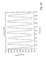
- Fig. 4A is a schematic illustration of the actual engine velocity for an example engine. It should be noted that the illustrated example does not necessarily represent the behaviour of a real engine. The present example should be seen as an illustrative example used to illustrate the functionality of a system and a method according to embodiments of the present invention.
- Fig. 4A illustrates the nominal engine velocity for a four cylinder engine, where one of the cylinders operates at 90% of its full capacity.
- the reduction in efficiency of one of the cylinders manifests itself as the lower amplitude (i.e. lower rpm) for every fourth peak.
- the sinusoidal behaviour of the engine velocity comes from the nature of the combustion cycle in a four cylinder engine.
- the tone wheel used to measure the velocity is non-ideal, meaning that the gaps have a size which varies within standard manufacturing tolerances.
- the effects of the non-ideal tone wheel are too small to be visually observable in the curve of Fig. 4 , the effects can be observed in a frequency analysis of the engine velocity trace.
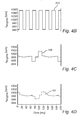
- Fig. 4B illustrates the AD-converted angular synchronous sensor signal 402 from the sensor 102.
- the AD-converted sensor signal is averaged to eliminate the variation in the velocity signal resulting from the nature of the combustion cycle in order to determine the nominal velocity variation. More specifically, the signal is averaged over a quarter of a revolution corresponding to one of the four strokes of a cycle of a four cylinder engine. It can be seen that the variation in rpm in Fig. 4C is significantly smaller as a result of the removal of the influence of the combustion cycle. This is a conventional signal processing step in measuring an engine velocity, considered to take place in the ADC 108, and is therefore not discussed in further detail.
- Fig. 4C thus illustrates the resulting averaged angular synchronous digital signal 109 provided by the ADC 108.
- the signal 109 is averaged using the CMA averaging procedure described above in relation to Fig. 2 , and the sequence of averaged samples form the filtered time continuous time synchronous digital signal 111 illustrated in Fig. 4D .
- the sampling points of the signal 111 does not coincide in time with the sampling points of the angular synchronous signal 109 of Fig. 4B . Instead, a time synchronous signal has been formed where the time between consecutive samples is constant and based on the sampling rate of the filter.
- the signal can now be provided to the ECU 112 for forming control signals 113 to the engine.
- the signal 111 is thus used in a feedback loop to control systems such as firing, air injection and fuel injection.
- the ECM time synchronous controllers generally operate in a relatively low frequency range, where the exact bandwidth is difficult to establish, but where control beyond approximately 10 Hz is often not of interest due to limitations in actuators such as valves and throttles.
- actuators such as valves and throttles.
- the relatively high frequency aliases relating from tone wheel non-uniformities does not lead to aliases influencing the control signal.
- variations in low frequency functions resulting from e.g. ignition/injection timings, valve leakage, duct resistance, etc. can contribute to aliases in the low frequency range which may influence the control signals.
- Fig. 5 is a flow chart outlining the general method steps of a method for operating an engine control system according to an embodiment of the invention. The method may advantageously be performed by a system according to any of the above descried embodiments, and the method will be described also with reference to the system 100 of Fig. 1 and the filter 110 of Fig. 2 .
- the method comprises acquiring 502 an analog angular synchronous signal 103 indicative of a rotational velocity of an element 104 being rotated by an engine 106, AD-converting 504 the analog angular synchronous signal 103 into a digital angular synchronous signal 109 and filtering 506 the digital angular synchronous signal 109 using a continuous moving average anti aliasing filter forming a filtered time continuous time synchronous digital signal 111.
- the filtered signal 111 is provided to a control 112 unit where a time synchronous control signal 113 is formed 508 based on the filtered digital signal 111.
- the control signal 113 is used for controlling 510 a performance parameter of the engine 106 based on the control signal 111.
- Fig. 6 is a flow chart outlining the general steps of filtering 506 the digital angular synchronous signal 109, described with reference to the filter illustrated in Fig. 2 .
- the method comprises integrating 602 the time continuous angular synchronous signal 109 to form an integrated signal 204.
- the integrated signal 204 is sampled 604 continuously and a average values are formed 606 from the current sample So and a previous sample S -2 , divided by the total sample time h*2, where h is the sample period.
- a filtered time continuous time synchronous output signal 111 is formed 608 from the resulting sequence of average values.
- the method may also comprise low-pass filtering of the analog angular synchronous signal 103 provided by the sensor 102 to remove any high frequency noise introduced by the sensor 102.
Landscapes
- Engineering & Computer Science (AREA)
- Physics & Mathematics (AREA)
- Theoretical Computer Science (AREA)
- General Physics & Mathematics (AREA)
- Geometry (AREA)
- General Engineering & Computer Science (AREA)
- Computer Hardware Design (AREA)
- Pure & Applied Mathematics (AREA)
- Computational Mathematics (AREA)
- Evolutionary Computation (AREA)
- Mathematical Analysis (AREA)
- Mathematical Optimization (AREA)
- Mathematical Physics (AREA)
- Combustion & Propulsion (AREA)
- Mechanical Engineering (AREA)
- Chemical & Material Sciences (AREA)
- Aviation & Aerospace Engineering (AREA)
- Data Mining & Analysis (AREA)
- Automation & Control Theory (AREA)
- Software Systems (AREA)
- Databases & Information Systems (AREA)
- Algebra (AREA)
- Operations Research (AREA)
- Feedback Control In General (AREA)
- Management, Administration, Business Operations System, And Electronic Commerce (AREA)
- Combined Controls Of Internal Combustion Engines (AREA)
- Electrical Control Of Air Or Fuel Supplied To Internal-Combustion Engine (AREA)
Abstract
Description
- The present invention relates to a control system for controlling a combustion engine and to a method for controlling a combustion engine.
- In modern combustion engines, engine control is dependent on accurate measurements of the engine velocity. The measured engine velocity acts as an input parameter for forming a range of control signals which in turn control various features and functions of the engine.
- Since the control signals influence the engine performance, and thereby the engine velocity, the engine control system can be referred to as closed loop system, or a feedback control system, wherein the control signal input is dependent on the engine output.
- Typically, the engine velocity of an engine is determined from a rotating element of the engine, where for example each rotation can trigger a sensor which in turn gives an indication of the engine velocity. The resulting signal from the sensor will thus be synchronized to the rotation of the rotating element, i.e. to the angle of rotation of the rotating element. Such a signal may also be referred to as being angular synchronous since trigger events occur at regular angular intervals.
- However, engine control systems are embodied in one or more engine control units comprising microprocessors operating at a fixed or variable clock rate, and such a clock rate can be refereed to as being time synchronous since events occur at regular time intervals.
- Thereby, it is required that the angular synchronous signal is converted to a time synchronous signal in order to be used in a control unit for forming a control signal.
- In view of above-mentioned drawbacks of the prior art, it is an object of the present invention to provide a control system for an internal combustion engine which addresses issues related to sampling of time synchronous signals.
- According to a first aspect of the invention, there is provided a control system for an internal combustion engine comprising: a sensor configured to measure a rotational velocity of a rotating element connected to said engine and to provide an angular synchronous analog signal representing the rotational velocity; an analog-to-digital-converter (ADC) connected to the sensor to receive and convert the angular synchronous analog signal into a time continuous angular synchronous digital signal; a filtering module configured to receive and filter the digital signal using a continuous moving average anti aliasing filter to form a filtered time continuous time synchronous digital signal; and a control unit configured to form at least one time synchronous control signal based on the filtered digital signal, wherein the control signal is provided to an engine control system for controlling a performance parameter of said engine.
- During development of a control system for an internal combustion engine in a vehicle, it has been observed that during some load cases and for some vehicles, low frequency oscillations in the engine may occur. The oscillations lead to vibrations propagating to the vehicle which in turn may lead to discomfort for the vehicle occupants. The oscillations, often having a frequency in the range of 3-7 Hz, have been observed for many types of vehicles such as small medium and large vehicles, vehicles with petrol and diesel engines, manual and automatic gearbox, vehicles with two-wheel drive and all-wheel drive, and irrespective of the number of cylinders.
- The present invention is based on the realization that the root cause of the oscillations may lie in the engine control system, an in particular in the conversion from an angular synchronous signal to a time synchronous signal. More particularly, the oscillation may occur due to signal aliasing of the sampled digital signal, which in turn is used as a basis for forming control signals for the engine. The signal from the sensor representing a rotational velocity can be seen as a pulse train, where each pulse is created when a trigger on the rotating element passes the sensor, i.e. when an interrupt occurs. The sensor signal can thus be referred to as a dynamically triggered signal. Thereby, the time between adjacent pulses is not constant; instead, it varies with varying engine velocity, whereas the sampling of the signal is performed with a predetermined sampling rate which is independent of the engine velocity. Moreover, aliases within the controlled bandwidth and below the bandwidth of the involved actuators of the system do occur. The overall sensitivity of the system to the aliases and the resulting oscillating behavior depends on tolerances of for example bushes, nozzles, valves, etc. Therefore, due to the variation of the specific parts between engines allowed within the given tolerances, one engine may be more prone to oscillatory behavior than another.
- Moreover, it has been realized that signal aliasing can be reduced by introducing a specific anti aliasing filtering module to filter the digital time continuous angular synchronous signal representing the engine velocity and forming a time continuous time synchronous signal to be used to create control signals for various functionality of the engine.
- According to one embodiment of the invention, the filtering module may comprise an integrator configured to integrate the time continuous signal to form an integrated signal; a sampling module configured to continuously sample the integrated signal; an averaging module configured to form average values from the current sample So and a previous sample S-2, divided by the total sample time h*2, where h is the sample period; and an output module configured to form a time continuous output signal from the average values formed by the averaging module.
- The described filtering module provides a filtering function which conserves energy and which improves the overall stability of the system. In particular, the above discussed filter does not deteriorate the energy transfer over the interface between the velocity domain and the time domain, where the angular synchronous signal is converted to a time synchronous signal.
- Moreover, it has been found that it is advantageous to form average values from a current sample So and from a previous sample S-2 being taken two samples before the current one. In other words, for a set of three consecutive samples, the first and the third sample is used to form an average over the entire time interval. This can be seen as a rolling window, so that a continuous moving average- (CMA) filter is formed. It has been found that a CMA-filter as described above using S-2 provides the most advantageous properties. Using S-1 may cause gain problems and using a value larger than 2 may cause lag problems. In the case For S-1, the gain at zero frequency is 0 dB, but for the frequency range beyond 10% of the Nyquist frequency, the gain increases steadily. On the other hand in case of S-n, n > 2, the bandwidth of the transferred signals over the interface will become unnecessarily low. For uneven values for n, signals up to the Nyquist frequency may be present, whereas for even n, the gain at the Nyquist frequency is 0. Accordingly, even though different values of n can be used, n = 2 has been shown to be preferable.
- According to one embodiment of the invention, the sensor may be a Hall-effect sensor forming a triggering signal when a trigger element of said rotating element passes the sensor. A Hall-effect sensor is a transducer that changes its output voltage as a result of a change in magnetic field adjacent to the sensor. Thereby, the Hall-effect sensor can induce a voltage output pulse, i.e. a triggering signal or interrupt signal, by detecting changes in the magnetic field when a rotating element rotates close to the sensor. The rotating element will comprise features which alter the magnetic field environment, typically arranged equidistantly spaced around the rotating element with a known angle between adjacent features, such that the angular velocity can be determined by detecting the time between consecutive triggering pulses of the sensor. It is understood that also other types of sensors may be used to measure the angular velocity of a rotating element.
- According to one embodiment of the invention, the rotating element may be a tone wheel or a ring gear connected to the combustion engine. A tone wheel typically comprises equidistantly spaced openings, and a ring gear comprises equidistantly spaced cogs, where the cogs or openings can act as triggering elements to trigger a sensor arranged to measure the engine velocity, such as a Hall-effect sensor.
- According to one embodiment of the invention, the performance parameter of the engine to control may be an engine velocity or a torque of the engine. During different load cases, the engine may be required to produce and maintain a particular torque or engine velocity, in which case the measured engine velocity signal is used as an input to provide a feedback loop where engine control signals are formed based on the engine velocity.
- According to one embodiment of the invention, the control signals may be configured to control fuel injection of the engine, which influences the operation of the engine both with respect to torque and velocity. Fuel injection is one of a range of functionalities in the engine influencing the engine operation, others are for example timing of the firing of the engine and the operation of the throttle valves in the air duct system.
- According to one embodiment of the invention, the control system may advantageously comprise an analog low-pass (LP) filter arranged and configured to remove high frequency noise from the angular synchronous analog signal provided by the sensor. The LP filter would then be arranged after the sensor to receive and filter the sensor signal before it is provided to the ADC.
- According to a second aspect of the invention, there is provided a method for operating an engine control system, the method comprising: acquiring an analog angular synchronous signal indicative of a rotational velocity of an element being rotated by an engine; converting said analog angular synchronous signal into a digital angular synchronous signal; filtering said digital angular synchronous signal using a continuous moving average anti aliasing filter forming a filtered time continuous time synchronous digital signal providing said signal to a control unit, in said control unit, forming a time synchronous control signal based on said filtered digital signal; and controlling a performance parameter of said engine based on said control signal.
- According to one embodiment of the invention, the step of filtering comprises integrating the time continuous signal to form an integrated signal; continuously sampling the integrated signal; forming average values from the current sample So and a previous sample S-2, divided by the total sample time h*2, where h is the sample period; and forming a time continuous output signal from said average values.
- According to one embodiment of the invention, the step of integrating may advantageously comprise forming a Left Riemann-sum of the time continuous angular synchronous signal.
- Effects and features of the second aspect of the invention are largely analogous to those described above in connection with the first aspects of the invention. Further elaboration of the filter properties and examples of the filter operation can be found in an earlier application,
European patent application 15182298.8 - Further features of, and advantages with, the present invention will become apparent when studying the appended claims and the following description. The skilled person realize that different features of the present invention may be combined to create embodiments other than those described in the following, without departing from the scope of the present invention.
- These and other aspects of the present invention will now be described in more detail, with reference to the appended drawings showing an example embodiment of the invention, wherein:
-
Fig. 1 is a schematic illustration of a system according to an embodiment of the invention; -
Fig. 2 is a schematic illustration of a filter incorporated in a control system according to an embodiment of the invention; -
Fig. 3 is a schematic illustration of a sensor signal from a system according to an embodiment of the invention; -
Figs. 4A-D are schematic graphs outlining signals at different stages of processing in a system according to an embodiment of the invention; -
Fig. 5 is a flow chart outlining the general steps of a method according to an embodiment of the invention; and -
Fig. 6 is a flow chart outlining the general steps of a method according to an embodiment of the invention. - In the present detailed description, various embodiments of the system and method according to the present invention are mainly described with reference to a non-ideal combustion engine for illustrating the functionality of the control system and method.
-
Fig. 1 schematically illustrates acontrol system 100 for aninternal combustion engine 106. The system comprises asensor 102 arranged and configured to measure a rotational velocity of theengine 106. Thesensor 102 is here described as a Hall-effect sensor 102 and therotating element 104 is here atone wheel 104 connected to theengine 106. The Hall-effect sensor 102 provides an angularsynchronous analog signal 103 representing the rotational velocity of theengine 106, which signal 102 in turn is provided to an AD-converter (ADC) 108 for forming a time continuous angular synchronousdigital signal 109. TheADC 108 is triggered by theoutput signal 103 from thesensor 102, and the sampling and AD-conversion taking place in theADC 108 is thus angular synchronous, thereby providing an angular synchronousdigital signal 109 as an output signal. Next, afiltering module 110 comprising a continuous moving average (CMA) anti aliasing (AA) filter receives and filters thedigital signal 109 using time-based sampling to form a filtered time continuous time synchronousdigital signal 111. The timesynchronous signal 111 is in turn provided to an engine control unit (ECU) 112 which forms one or more time synchronous control signals 113 to be provided to engine control algorithms for controlling various elements of theengine 106. The control signals 113 can for example be configured to control fuel injection, firing and/or throttle valves of theengine 106. It is understood that providing the control signals 113 to the various parts of theengine 106 comprises converting the respective signal into a format suitable for controlling the respective actuators and/or functions. -
Fig. 2 is a schematic illustration of theCMA anti-aliasing filter 110. The filter comprises anintegrator 202 configured to integrate the time continuous angularsynchronous signal 109 to form anintegrated signal 204. The integrated 204 signal is provided to asampling module 206, or a sampling circuit, which is configured to continuously sample theintegrated signal 204 using a fixed sampling rate. The sampledsignal 208 is then passed to anaveraging module 210 configured to form an average value from the current sample So and a previous sample S0-n, where n=2, divided by the total sample time 2h, where h is the sample period. The averagingmodule 210 is connected to anoutput module 214 which outputs a filtered timecontinuous signal 108 based on the sequence of average values formed by the averagingmodule 210. - The
filter 110 for a time continuous input signal u can be mathematically described as
continuous output signal 111. - Even though the
ADC 108, thefilter 110 and theECU 112 are illustrated herein as separate units, the control system may equally well be implemented in one or more general purpose ECUs or equivalent processing circuitry. -
Fig. 3 schematically illustrates the functionality of thesensor 102, here illustrated as a Hall-effect sensor 102. The sensor comprises two Hall-effect elements 302a-b which detect the changes inmagnetic field ΔB 304 due to the structure, i.e. the teeth or gaps, of thetone wheel 104. For each passing of a tooth/gap of thetone wheel 104, a voltage pulse is provided by thesensor 102 to form theoutput signal 103. Since the elements triggering an output pulse, i.e. the triggeringelements 306 of thetone wheel 104 are equidistantly spaced, the angle betweenadjacent elements 306 is constant. Thereby, theoutput signal 103 from thesensor 102 is synchronized with the rotation of therotating element 104 and thus with rotational velocity of theengine 106. Accordingly, the output signal from thesensor 102 is referred to as an angularsynchronous analog signal 103. -
Fig. 4A is a schematic illustration of the actual engine velocity for an example engine. It should be noted that the illustrated example does not necessarily represent the behaviour of a real engine. The present example should be seen as an illustrative example used to illustrate the functionality of a system and a method according to embodiments of the present invention. - In particular,
Fig. 4A illustrates the nominal engine velocity for a four cylinder engine, where one of the cylinders operates at 90% of its full capacity. The reduction in efficiency of one of the cylinders manifests itself as the lower amplitude (i.e. lower rpm) for every fourth peak. The sinusoidal behaviour of the engine velocity comes from the nature of the combustion cycle in a four cylinder engine. Moreover, in the present example, it is assumed that the tone wheel used to measure the velocity is non-ideal, meaning that the gaps have a size which varies within standard manufacturing tolerances. However, even though the effects of the non-ideal tone wheel are too small to be visually observable in the curve ofFig. 4 , the effects can be observed in a frequency analysis of the engine velocity trace. -
Fig. 4B illustrates the AD-converted angularsynchronous sensor signal 402 from thesensor 102. - Next, illustrated in
Fig. 4C , the AD-converted sensor signal is averaged to eliminate the variation in the velocity signal resulting from the nature of the combustion cycle in order to determine the nominal velocity variation. More specifically, the signal is averaged over a quarter of a revolution corresponding to one of the four strokes of a cycle of a four cylinder engine. It can be seen that the variation in rpm inFig. 4C is significantly smaller as a result of the removal of the influence of the combustion cycle. This is a conventional signal processing step in measuring an engine velocity, considered to take place in theADC 108, and is therefore not discussed in further detail.Fig. 4C thus illustrates the resulting averaged angular synchronousdigital signal 109 provided by theADC 108. - As a next step in the filtering procedure, illustrated in
Fig. 4D , thesignal 109 is averaged using the CMA averaging procedure described above in relation toFig. 2 , and the sequence of averaged samples form the filtered time continuous time synchronousdigital signal 111 illustrated inFig. 4D . Here, it can be seen that the sampling points of thesignal 111 does not coincide in time with the sampling points of the angularsynchronous signal 109 ofFig. 4B . Instead, a time synchronous signal has been formed where the time between consecutive samples is constant and based on the sampling rate of the filter. - The signal can now be provided to the
ECU 112 for formingcontrol signals 113 to the engine. Thesignal 111 is thus used in a feedback loop to control systems such as firing, air injection and fuel injection. - The ECM time synchronous controllers generally operate in a relatively low frequency range, where the exact bandwidth is difficult to establish, but where control beyond approximately 10 Hz is often not of interest due to limitations in actuators such as valves and throttles. In view of this, it has been observed that the relatively high frequency aliases relating from tone wheel non-uniformities does not lead to aliases influencing the control signal. Instead, variations in low frequency functions resulting from e.g. ignition/injection timings, valve leakage, duct resistance, etc. can contribute to aliases in the low frequency range which may influence the control signals.
-
Fig. 5 is a flow chart outlining the general method steps of a method for operating an engine control system according to an embodiment of the invention. The method may advantageously be performed by a system according to any of the above descried embodiments, and the method will be described also with reference to thesystem 100 ofFig. 1 and thefilter 110 ofFig. 2 . - The method comprises acquiring 502 an analog angular
synchronous signal 103 indicative of a rotational velocity of anelement 104 being rotated by anengine 106, AD-converting 504 the analog angularsynchronous signal 103 into a digital angularsynchronous signal 109 and filtering 506 the digital angularsynchronous signal 109 using a continuous moving average anti aliasing filter forming a filtered time continuous time synchronousdigital signal 111. The filteredsignal 111 is provided to acontrol 112 unit where a timesynchronous control signal 113 is formed 508 based on the filtereddigital signal 111. Finally, thecontrol signal 113 is used for controlling 510 a performance parameter of theengine 106 based on thecontrol signal 111. -
Fig. 6 is a flow chart outlining the general steps of filtering 506 the digital angularsynchronous signal 109, described with reference to the filter illustrated inFig. 2 . The method comprises integrating 602 the time continuous angularsynchronous signal 109 to form anintegrated signal 204. Theintegrated signal 204 is sampled 604 continuously and a average values are formed 606 from the current sample So and a previous sample S-2, divided by the total sample time h*2, where h is the sample period. Finally a filtered time continuous timesynchronous output signal 111 is formed 608 from the resulting sequence of average values. - The method may also comprise low-pass filtering of the analog angular
synchronous signal 103 provided by thesensor 102 to remove any high frequency noise introduced by thesensor 102. - Even though the invention has been described with reference to specific exemplifying embodiments thereof, many different alterations, modifications and the like will become apparent for those skilled in the art. Also, it should be noted that parts of the system and method may be omitted, interchanged or arranged in various ways, the system and method yet being able to perform the functionality of the present invention.
- Additionally, variations to the disclosed embodiments can be understood and effected by the skilled person in practicing the claimed invention, from a study of the drawings, the disclosure, and the appended claims. In the claims, the word "comprising" does not exclude other elements or steps, and the indefinite article "a" or "an" does not exclude a plurality. The mere fact that certain measures are recited in mutually different dependent claims does not indicate that a combination of these measures cannot be used to advantage.
Claims (14)
- A control system for an internal combustion engine comprising:a sensor configured to measure a rotational velocity of a rotating element connected to said engine and to provide an angular synchronous analog signal representing said rotational velocity;an analog-to-digital converter connected to said sensor to receive and convert said angular synchronous analog signal into a time continuous angular synchronous digital signal;a filtering module configured to receive and filter said digital signal using a continuous moving average anti aliasing filter to form a filtered time continuous time synchronous digital signal; anda control unit configured to form at least one time synchronous control signal based on said filtered digital signal, wherein said control signal is provided to an engine control system for controlling a performance parameter of said engine.
- The control system according to claim 1, wherein said filtering module comprises:an integrator configured to integrate said time continuous signal to form an integrated signal;a sampling module configured to continuously sample said integrated signal;an averaging module configured to form average values from the current sample So and a previous sample S-2, divided by the total sample time h*2, where h is the sample period; andan output module configured to form a time continuous output signal from said average values formed by said averaging module.
- The control system according to claim 1 or 2, wherein said sensor is a Hall-effect sensor forming a triggering signal when a trigger element of said rotating element passes said sensor.
- The control system according to claim 3, wherein said rotating element comprises a plurality of equidistantly spaced triggering elements, and wherein an angle between adjacent triggering elements is known.
- The control system according to any one of the preceding claims, wherein said rotating element comprises a tone wheel or a ring gear connected to said combustion engine.
- The control system according to any one of the preceding claims, wherein said performance parameter of said engine is an engine velocity or a torque of said engine.
- The control system according to any one of the preceding claims, wherein said wherein said control signals are configured to control fuel injection, firing and/or throttle valves of said engine.
- The control system according to any one of the preceding claims, further comprising an analog low-pass filter arranged and configured to remove high frequency noise from said angular synchronous analog signal provided by said sensor.
- A method for operating an engine control system, said method comprising:acquiring an analog angular synchronous signal indicative of a rotational velocity of an element being rotated by an engine;converting said analog angular synchronous signal into a digital angular synchronous signal;filtering said digital angular synchronous signal using a continuous moving average anti aliasing filter forming a filtered time continuous time synchronous digital signalproviding said signal to a control unit;in said control unit, forming a time synchronous control signal based on said filtered digital signal; andcontrolling a performance parameter of said engine based on said control signal.
- The method according to claim 9, wherein said step of filtering comprises:integrating said time continuous angular synchronous signal to form an integrated signal;continuously sampling said integrated signal;forming average values from the current sample So and a previous sample S-2, divided by the total sample time h*2, where h is the sample period; andforming a time continuous output signal from said average values.
- The method according to claim 10, wherein said step of integrating comprises forming a Left Riemann-sum of said time continuous angular synchronous signal.
- The method according to claim 10 or 11, wherein said performance parameter of said engine is an engine velocity or a torque of said engine
- The method according to any one of claims 10 to 12, wherein said control signal is configured to control fuel injection firing, and/or throttle valves of said engine.
- The method according to any one of claims 9 to 13, further comprising low-pass filtering said analog angular synchronous signal to remove high frequency noise.
Applications Claiming Priority (1)
| Application Number | Priority Date | Filing Date | Title |
|---|---|---|---|
| EP15182298.8A EP3136267A1 (en) | 2015-08-25 | 2015-08-25 | Method and system for control and co-simulation of physical systems |
Publications (2)
| Publication Number | Publication Date |
|---|---|
| EP3153979A1 true EP3153979A1 (en) | 2017-04-12 |
| EP3153979B1 EP3153979B1 (en) | 2024-12-11 |
Family
ID=54106120
Family Applications (3)
| Application Number | Title | Priority Date | Filing Date |
|---|---|---|---|
| EP15182298.8A Ceased EP3136267A1 (en) | 2015-08-25 | 2015-08-25 | Method and system for control and co-simulation of physical systems |
| EP15191048.6A Active EP3153979B1 (en) | 2015-08-25 | 2015-10-22 | Method and system for control of a combustion engine |
| EP15194478.2A Ceased EP3156921A1 (en) | 2015-08-25 | 2015-11-13 | Method and system for controlling a co-simulation system |
Family Applications Before (1)
| Application Number | Title | Priority Date | Filing Date |
|---|---|---|---|
| EP15182298.8A Ceased EP3136267A1 (en) | 2015-08-25 | 2015-08-25 | Method and system for control and co-simulation of physical systems |
Family Applications After (1)
| Application Number | Title | Priority Date | Filing Date |
|---|---|---|---|
| EP15194478.2A Ceased EP3156921A1 (en) | 2015-08-25 | 2015-11-13 | Method and system for controlling a co-simulation system |
Country Status (3)
| Country | Link |
|---|---|
| US (1) | US10296706B2 (en) |
| EP (3) | EP3136267A1 (en) |
| CN (1) | CN106844291B (en) |
Families Citing this family (7)
| Publication number | Priority date | Publication date | Assignee | Title |
|---|---|---|---|---|
| US11216604B2 (en) | 2017-06-02 | 2022-01-04 | The Mathworks, Inc. | Systems and methods for co-simulation |
| EP3518216A1 (en) * | 2018-01-30 | 2019-07-31 | Volvo Car Corporation | Co-simulation system with delay compensation and method for control of co-simulation system |
| CN108416132B (en) * | 2018-02-28 | 2021-11-12 | 东南大学 | Automatic variable-step-size simulation acceleration method for distributed photovoltaic cluster |
| US11042675B2 (en) * | 2018-06-01 | 2021-06-22 | The Mathworks, Inc. | Systems and methods for automatically realizing models for co-simulation |
| EP3579126A1 (en) | 2018-06-07 | 2019-12-11 | Kompetenzzentrum - Das virtuelle Fahrzeug Forschungsgesellschaft mbH | Co-simulation method and device |
| CN109375896B (en) * | 2018-10-29 | 2023-01-24 | 广东电网有限责任公司 | A kind of similar integration method and device |
| DE102019218458A1 (en) * | 2019-11-28 | 2021-06-02 | Robert Bosch Gmbh | Method and software tool for making executable specifications in the system development or validation of complex functional systems |
Citations (5)
| Publication number | Priority date | Publication date | Assignee | Title |
|---|---|---|---|---|
| US20060117834A1 (en) * | 2004-12-06 | 2006-06-08 | Denso Corporation | Engine knocking detection apparatus which adjusts passband of sensor signal bandpass filter in accordance with increases in crankshaft angle |
| US20060206254A1 (en) * | 2005-03-14 | 2006-09-14 | Spectral Dynamics, Inc. | Real-time spectral analysis of internal combustion engine knock |
| EP1905989A2 (en) * | 2006-09-29 | 2008-04-02 | Delphi Technologies, Inc. | Cylinder-pressure-based electronic engine controller and method |
| US20090118989A1 (en) * | 2007-11-07 | 2009-05-07 | Padhi Kabi P | Knock signal detection in automotive systems |
| US20100010724A1 (en) * | 2008-07-11 | 2010-01-14 | Tula Technology, Inc. | Internal combustion engine control for improved fuel efficiency |
Family Cites Families (8)
| Publication number | Priority date | Publication date | Assignee | Title |
|---|---|---|---|---|
| US20020059052A1 (en) * | 2000-09-12 | 2002-05-16 | Mellanox Technologies Ltd. | Co-simulation of network components |
| US20100063786A1 (en) * | 2008-09-11 | 2010-03-11 | Harke Michael C | Co-Simulation Process |
| US9577608B2 (en) * | 2009-08-14 | 2017-02-21 | Qualcomm Incorporated | Discrete time lowpass filter |
| AT511272A1 (en) | 2010-10-15 | 2012-10-15 | Kompetenzzentrum Das Virtuelle Fahrzeug Forschungsgmbh | COUPLING METHODOLOGY FOR NON-ITERATIVE CO SIMULATION |
| US9166563B2 (en) * | 2011-10-25 | 2015-10-20 | Actiwave Ab | Asynchronous sample rate converter |
| US9223754B2 (en) | 2012-06-29 | 2015-12-29 | Dassault Systèmes, S.A. | Co-simulation procedures using full derivatives of output variables |
| US9435310B2 (en) * | 2013-03-07 | 2016-09-06 | Cummins Inc. | Hydraulic start-of-injection detecting system and method |
| CN103176472B (en) * | 2013-03-13 | 2015-09-09 | 长沙理工大学 | A kind of four-wheel drive pure electric vehicle hardware-in-loop simulation experimental system |
-
2015
- 2015-08-25 EP EP15182298.8A patent/EP3136267A1/en not_active Ceased
- 2015-10-22 EP EP15191048.6A patent/EP3153979B1/en active Active
- 2015-11-13 EP EP15194478.2A patent/EP3156921A1/en not_active Ceased
-
2016
- 2016-08-09 US US15/232,261 patent/US10296706B2/en active Active
- 2016-08-18 CN CN201610682817.0A patent/CN106844291B/en active Active
Patent Citations (5)
| Publication number | Priority date | Publication date | Assignee | Title |
|---|---|---|---|---|
| US20060117834A1 (en) * | 2004-12-06 | 2006-06-08 | Denso Corporation | Engine knocking detection apparatus which adjusts passband of sensor signal bandpass filter in accordance with increases in crankshaft angle |
| US20060206254A1 (en) * | 2005-03-14 | 2006-09-14 | Spectral Dynamics, Inc. | Real-time spectral analysis of internal combustion engine knock |
| EP1905989A2 (en) * | 2006-09-29 | 2008-04-02 | Delphi Technologies, Inc. | Cylinder-pressure-based electronic engine controller and method |
| US20090118989A1 (en) * | 2007-11-07 | 2009-05-07 | Padhi Kabi P | Knock signal detection in automotive systems |
| US20100010724A1 (en) * | 2008-07-11 | 2010-01-14 | Tula Technology, Inc. | Internal combustion engine control for improved fuel efficiency |
Also Published As
| Publication number | Publication date |
|---|---|
| EP3156921A1 (en) | 2017-04-19 |
| CN106844291A (en) | 2017-06-13 |
| US20170061069A1 (en) | 2017-03-02 |
| CN106844291B (en) | 2021-12-24 |
| EP3136267A1 (en) | 2017-03-01 |
| US10296706B2 (en) | 2019-05-21 |
| EP3153979B1 (en) | 2024-12-11 |
Similar Documents
| Publication | Publication Date | Title |
|---|---|---|
| EP3153979B1 (en) | Method and system for control of a combustion engine | |
| US7761256B2 (en) | Method and system for use in analyzing vibrations of a variable speed rotating body | |
| US6827063B2 (en) | Method and device for establishment of a signal pattern based on crank angle of internal combustion engine | |
| JP4312762B2 (en) | Misfire detection in internal combustion engines | |
| US8577645B2 (en) | Air/fuel mixture imbalance diagnostic systems and methods | |
| US5789658A (en) | Adaptation method for correcting tolerances of a transducer wheel | |
| US4215404A (en) | Automatic device for diagnostic checkup of vehicles | |
| US9562841B2 (en) | Engine output soot diagnostic control system based on transient drive cycle detection | |
| EP1804044A2 (en) | Misfire detecting apparatus for internal combustion engine | |
| EP1972780A1 (en) | Vehicle diagnosis system and method | |
| DE102015205917B4 (en) | Cylinder internal pressure detecting device for an internal combustion engine | |
| US20120290168A1 (en) | State estimation, diagnosis and control using equivalent time sampling | |
| JP4927177B2 (en) | ANALYZER AND METHOD FOR DETECTING ENGINE CHARACTERISTIC VALUE | |
| CN104481694B (en) | Self-diagnosis method for rotating speed of engine crankshaft | |
| CN106796117A (en) | Sensor for determining at least one rotational characteristic of rotating element | |
| US7644608B2 (en) | Intake air temperature sensor diagnostic | |
| CN101952579B (en) | Method for producing an internal combustion engine operating cycle synchronization signal | |
| EP1756412B1 (en) | Detection of analogue vehicle signals synchronous with the crankshaft | |
| US20140311230A1 (en) | Method for determining segment times of a sensor wheel of an iternal combustion engine | |
| CN102137996A (en) | Method for Correcting Cylinder Unbalance in Internal Combustion Engine | |
| DE102009026971B4 (en) | Method and device for providing a speed and temperature information of a charging device for an internal combustion engine | |
| Corti et al. | Real-time evaluation of IMEP and ROHR-related parameters | |
| US5000039A (en) | Mass air flow integrator | |
| DE69427984T2 (en) | Misfire detection through acceleration differentiation | |
| CN209492391U (en) | A kind of modularization Speed limiting system for fork truck |
Legal Events
| Date | Code | Title | Description |
|---|---|---|---|
| PUAI | Public reference made under article 153(3) epc to a published international application that has entered the european phase |
Free format text: ORIGINAL CODE: 0009012 |
|
| STAA | Information on the status of an ep patent application or granted ep patent |
Free format text: STATUS: THE APPLICATION HAS BEEN PUBLISHED |
|
| AK | Designated contracting states |
Kind code of ref document: A1 Designated state(s): AL AT BE BG CH CY CZ DE DK EE ES FI FR GB GR HR HU IE IS IT LI LT LU LV MC MK MT NL NO PL PT RO RS SE SI SK SM TR |
|
| AX | Request for extension of the european patent |
Extension state: BA ME |
|
| STAA | Information on the status of an ep patent application or granted ep patent |
Free format text: STATUS: REQUEST FOR EXAMINATION WAS MADE |
|
| 17P | Request for examination filed |
Effective date: 20171012 |
|
| RBV | Designated contracting states (corrected) |
Designated state(s): AL AT BE BG CH CY CZ DE DK EE ES FI FR GB GR HR HU IE IS IT LI LT LU LV MC MK MT NL NO PL PT RO RS SE SI SK SM TR |
|
| STAA | Information on the status of an ep patent application or granted ep patent |
Free format text: STATUS: EXAMINATION IS IN PROGRESS |
|
| 17Q | First examination report despatched |
Effective date: 20191128 |
|
| P01 | Opt-out of the competence of the unified patent court (upc) registered |
Effective date: 20230828 |
|
| REG | Reference to a national code |
Ref country code: DE Ref legal event code: R079 Free format text: PREVIOUS MAIN CLASS: G06F0017500000 Ipc: G06F0030150000 Ref country code: DE Ref legal event code: R079 Ref document number: 602015090612 Country of ref document: DE Free format text: PREVIOUS MAIN CLASS: G06F0017500000 Ipc: G06F0030150000 |
|
| GRAP | Despatch of communication of intention to grant a patent |
Free format text: ORIGINAL CODE: EPIDOSNIGR1 |
|
| STAA | Information on the status of an ep patent application or granted ep patent |
Free format text: STATUS: GRANT OF PATENT IS INTENDED |
|
| RIC1 | Information provided on ipc code assigned before grant |
Ipc: F02D 41/28 20060101ALN20240723BHEP Ipc: F02D 41/14 20060101ALI20240723BHEP Ipc: G06F 30/20 20200101ALI20240723BHEP Ipc: G06F 30/15 20200101AFI20240723BHEP |
|
| INTG | Intention to grant announced |
Effective date: 20240802 |
|
| GRAS | Grant fee paid |
Free format text: ORIGINAL CODE: EPIDOSNIGR3 |
|
| GRAA | (expected) grant |
Free format text: ORIGINAL CODE: 0009210 |
|
| STAA | Information on the status of an ep patent application or granted ep patent |
Free format text: STATUS: THE PATENT HAS BEEN GRANTED |
|
| AK | Designated contracting states |
Kind code of ref document: B1 Designated state(s): AL AT BE BG CH CY CZ DE DK EE ES FI FR GB GR HR HU IE IS IT LI LT LU LV MC MK MT NL NO PL PT RO RS SE SI SK SM TR |
|
| REG | Reference to a national code |
Ref country code: GB Ref legal event code: FG4D |
|
| REG | Reference to a national code |
Ref country code: CH Ref legal event code: EP |
|
| REG | Reference to a national code |
Ref country code: DE Ref legal event code: R096 Ref document number: 602015090612 Country of ref document: DE |
|
| REG | Reference to a national code |
Ref country code: IE Ref legal event code: FG4D |
|
| REG | Reference to a national code |
Ref country code: LT Ref legal event code: MG9D |
|
| PG25 | Lapsed in a contracting state [announced via postgrant information from national office to epo] |
Ref country code: HR Free format text: LAPSE BECAUSE OF FAILURE TO SUBMIT A TRANSLATION OF THE DESCRIPTION OR TO PAY THE FEE WITHIN THE PRESCRIBED TIME-LIMIT Effective date: 20241211 |
|
| PG25 | Lapsed in a contracting state [announced via postgrant information from national office to epo] |
Ref country code: FI Free format text: LAPSE BECAUSE OF FAILURE TO SUBMIT A TRANSLATION OF THE DESCRIPTION OR TO PAY THE FEE WITHIN THE PRESCRIBED TIME-LIMIT Effective date: 20241211 |
|
| PG25 | Lapsed in a contracting state [announced via postgrant information from national office to epo] |
Ref country code: BG Free format text: LAPSE BECAUSE OF FAILURE TO SUBMIT A TRANSLATION OF THE DESCRIPTION OR TO PAY THE FEE WITHIN THE PRESCRIBED TIME-LIMIT Effective date: 20241211 |
|
| REG | Reference to a national code |
Ref country code: NL Ref legal event code: MP Effective date: 20241211 |
|
| PG25 | Lapsed in a contracting state [announced via postgrant information from national office to epo] |
Ref country code: ES Free format text: LAPSE BECAUSE OF FAILURE TO SUBMIT A TRANSLATION OF THE DESCRIPTION OR TO PAY THE FEE WITHIN THE PRESCRIBED TIME-LIMIT Effective date: 20241211 |
|
| PG25 | Lapsed in a contracting state [announced via postgrant information from national office to epo] |
Ref country code: NO Free format text: LAPSE BECAUSE OF FAILURE TO SUBMIT A TRANSLATION OF THE DESCRIPTION OR TO PAY THE FEE WITHIN THE PRESCRIBED TIME-LIMIT Effective date: 20250311 |
|
| PG25 | Lapsed in a contracting state [announced via postgrant information from national office to epo] |
Ref country code: LV Free format text: LAPSE BECAUSE OF FAILURE TO SUBMIT A TRANSLATION OF THE DESCRIPTION OR TO PAY THE FEE WITHIN THE PRESCRIBED TIME-LIMIT Effective date: 20241211 Ref country code: GR Free format text: LAPSE BECAUSE OF FAILURE TO SUBMIT A TRANSLATION OF THE DESCRIPTION OR TO PAY THE FEE WITHIN THE PRESCRIBED TIME-LIMIT Effective date: 20250312 |
|
| PG25 | Lapsed in a contracting state [announced via postgrant information from national office to epo] |
Ref country code: RS Free format text: LAPSE BECAUSE OF FAILURE TO SUBMIT A TRANSLATION OF THE DESCRIPTION OR TO PAY THE FEE WITHIN THE PRESCRIBED TIME-LIMIT Effective date: 20250311 |
|
| PG25 | Lapsed in a contracting state [announced via postgrant information from national office to epo] |
Ref country code: NL Free format text: LAPSE BECAUSE OF FAILURE TO SUBMIT A TRANSLATION OF THE DESCRIPTION OR TO PAY THE FEE WITHIN THE PRESCRIBED TIME-LIMIT Effective date: 20241211 |
|
| REG | Reference to a national code |
Ref country code: AT Ref legal event code: MK05 Ref document number: 1750968 Country of ref document: AT Kind code of ref document: T Effective date: 20241211 |
|
| PG25 | Lapsed in a contracting state [announced via postgrant information from national office to epo] |
Ref country code: SM Free format text: LAPSE BECAUSE OF FAILURE TO SUBMIT A TRANSLATION OF THE DESCRIPTION OR TO PAY THE FEE WITHIN THE PRESCRIBED TIME-LIMIT Effective date: 20241211 |
|
| PG25 | Lapsed in a contracting state [announced via postgrant information from national office to epo] |
Ref country code: PL Free format text: LAPSE BECAUSE OF FAILURE TO SUBMIT A TRANSLATION OF THE DESCRIPTION OR TO PAY THE FEE WITHIN THE PRESCRIBED TIME-LIMIT Effective date: 20241211 |
|
| PG25 | Lapsed in a contracting state [announced via postgrant information from national office to epo] |
Ref country code: IS Free format text: LAPSE BECAUSE OF FAILURE TO SUBMIT A TRANSLATION OF THE DESCRIPTION OR TO PAY THE FEE WITHIN THE PRESCRIBED TIME-LIMIT Effective date: 20250411 |
|
| PG25 | Lapsed in a contracting state [announced via postgrant information from national office to epo] |
Ref country code: PT Free format text: LAPSE BECAUSE OF FAILURE TO SUBMIT A TRANSLATION OF THE DESCRIPTION OR TO PAY THE FEE WITHIN THE PRESCRIBED TIME-LIMIT Effective date: 20250411 |
|
| PG25 | Lapsed in a contracting state [announced via postgrant information from national office to epo] |
Ref country code: EE Free format text: LAPSE BECAUSE OF FAILURE TO SUBMIT A TRANSLATION OF THE DESCRIPTION OR TO PAY THE FEE WITHIN THE PRESCRIBED TIME-LIMIT Effective date: 20241211 |
|
| PG25 | Lapsed in a contracting state [announced via postgrant information from national office to epo] |
Ref country code: AT Free format text: LAPSE BECAUSE OF FAILURE TO SUBMIT A TRANSLATION OF THE DESCRIPTION OR TO PAY THE FEE WITHIN THE PRESCRIBED TIME-LIMIT Effective date: 20241211 Ref country code: RO Free format text: LAPSE BECAUSE OF FAILURE TO SUBMIT A TRANSLATION OF THE DESCRIPTION OR TO PAY THE FEE WITHIN THE PRESCRIBED TIME-LIMIT Effective date: 20241211 |
|
| PG25 | Lapsed in a contracting state [announced via postgrant information from national office to epo] |
Ref country code: SK Free format text: LAPSE BECAUSE OF FAILURE TO SUBMIT A TRANSLATION OF THE DESCRIPTION OR TO PAY THE FEE WITHIN THE PRESCRIBED TIME-LIMIT Effective date: 20241211 |
|
| PG25 | Lapsed in a contracting state [announced via postgrant information from national office to epo] |
Ref country code: CZ Free format text: LAPSE BECAUSE OF FAILURE TO SUBMIT A TRANSLATION OF THE DESCRIPTION OR TO PAY THE FEE WITHIN THE PRESCRIBED TIME-LIMIT Effective date: 20241211 |
|
| PG25 | Lapsed in a contracting state [announced via postgrant information from national office to epo] |
Ref country code: IT Free format text: LAPSE BECAUSE OF FAILURE TO SUBMIT A TRANSLATION OF THE DESCRIPTION OR TO PAY THE FEE WITHIN THE PRESCRIBED TIME-LIMIT Effective date: 20241211 |
|
| PG25 | Lapsed in a contracting state [announced via postgrant information from national office to epo] |
Ref country code: SE Free format text: LAPSE BECAUSE OF FAILURE TO SUBMIT A TRANSLATION OF THE DESCRIPTION OR TO PAY THE FEE WITHIN THE PRESCRIBED TIME-LIMIT Effective date: 20241211 |
|
| REG | Reference to a national code |
Ref country code: DE Ref legal event code: R097 Ref document number: 602015090612 Country of ref document: DE |
|
| PG25 | Lapsed in a contracting state [announced via postgrant information from national office to epo] |
Ref country code: DK Free format text: LAPSE BECAUSE OF FAILURE TO SUBMIT A TRANSLATION OF THE DESCRIPTION OR TO PAY THE FEE WITHIN THE PRESCRIBED TIME-LIMIT Effective date: 20241211 |
|
| PLBE | No opposition filed within time limit |
Free format text: ORIGINAL CODE: 0009261 |
|
| STAA | Information on the status of an ep patent application or granted ep patent |
Free format text: STATUS: NO OPPOSITION FILED WITHIN TIME LIMIT |
|
| PGFP | Annual fee paid to national office [announced via postgrant information from national office to epo] |
Ref country code: FR Payment date: 20250924 Year of fee payment: 11 |
|
| REG | Reference to a national code |
Ref country code: CH Ref legal event code: L10 Free format text: ST27 STATUS EVENT CODE: U-0-0-L10-L00 (AS PROVIDED BY THE NATIONAL OFFICE) Effective date: 20251022 |
|
| 26N | No opposition filed |
Effective date: 20250912 |
|
| PGFP | Annual fee paid to national office [announced via postgrant information from national office to epo] |
Ref country code: DE Payment date: 20250923 Year of fee payment: 11 |
|
| REG | Reference to a national code |
Ref country code: CH Ref legal event code: H13 Free format text: ST27 STATUS EVENT CODE: U-0-0-H10-H13 (AS PROVIDED BY THE NATIONAL OFFICE) Effective date: 20260527 |
|
| PG25 | Lapsed in a contracting state [announced via postgrant information from national office to epo] |
Ref country code: LU Free format text: LAPSE BECAUSE OF NON-PAYMENT OF DUE FEES Effective date: 20251022 |
|
| REG | Reference to a national code |
Ref country code: BE Ref legal event code: MM Effective date: 20251031 |
|
| GBPC | Gb: european patent ceased through non-payment of renewal fee |
Effective date: 20251022 |
|
| PG25 | Lapsed in a contracting state [announced via postgrant information from national office to epo] |
Ref country code: LT Free format text: LAPSE BECAUSE OF FAILURE TO SUBMIT A TRANSLATION OF THE DESCRIPTION OR TO PAY THE FEE WITHIN THE PRESCRIBED TIME-LIMIT Effective date: 20241211 |
|
| PG25 | Lapsed in a contracting state [announced via postgrant information from national office to epo] |
Ref country code: MC Free format text: LAPSE BECAUSE OF FAILURE TO SUBMIT A TRANSLATION OF THE DESCRIPTION OR TO PAY THE FEE WITHIN THE PRESCRIBED TIME-LIMIT Effective date: 20241211 |
|
| PG25 | Lapsed in a contracting state [announced via postgrant information from national office to epo] |
Ref country code: GB Free format text: LAPSE BECAUSE OF NON-PAYMENT OF DUE FEES Effective date: 20251022 |
|
| PG25 | Lapsed in a contracting state [announced via postgrant information from national office to epo] |
Ref country code: BE Free format text: LAPSE BECAUSE OF NON-PAYMENT OF DUE FEES Effective date: 20251031 Ref country code: CH Free format text: LAPSE BECAUSE OF NON-PAYMENT OF DUE FEES Effective date: 20251031 |