EP3153683A1 - Throttle drive actuator for an engine - Google Patents
Throttle drive actuator for an engine Download PDFInfo
- Publication number
- EP3153683A1 EP3153683A1 EP16189895.2A EP16189895A EP3153683A1 EP 3153683 A1 EP3153683 A1 EP 3153683A1 EP 16189895 A EP16189895 A EP 16189895A EP 3153683 A1 EP3153683 A1 EP 3153683A1
- Authority
- EP
- European Patent Office
- Prior art keywords
- magnet
- armature
- throttle
- drive actuator
- magnetic field
- Prior art date
- Legal status (The legal status is an assumption and is not a legal conclusion. Google has not performed a legal analysis and makes no representation as to the accuracy of the status listed.)
- Granted
Links
- 238000004804 winding Methods 0.000 claims abstract description 17
- 230000008901 benefit Effects 0.000 description 3
- 238000000034 method Methods 0.000 description 3
- 230000004048 modification Effects 0.000 description 3
- 238000012986 modification Methods 0.000 description 3
- 238000010586 diagram Methods 0.000 description 2
- 230000004044 response Effects 0.000 description 2
- 230000009471 action Effects 0.000 description 1
- 238000002485 combustion reaction Methods 0.000 description 1
- 239000004020 conductor Substances 0.000 description 1
- 230000005672 electromagnetic field Effects 0.000 description 1
Images



Classifications
-
- F—MECHANICAL ENGINEERING; LIGHTING; HEATING; WEAPONS; BLASTING
- F02—COMBUSTION ENGINES; HOT-GAS OR COMBUSTION-PRODUCT ENGINE PLANTS
- F02D—CONTROLLING COMBUSTION ENGINES
- F02D41/00—Electrical control of supply of combustible mixture or its constituents
- F02D41/0002—Controlling intake air
-
- F—MECHANICAL ENGINEERING; LIGHTING; HEATING; WEAPONS; BLASTING
- F02—COMBUSTION ENGINES; HOT-GAS OR COMBUSTION-PRODUCT ENGINE PLANTS
- F02D—CONTROLLING COMBUSTION ENGINES
- F02D11/00—Arrangements for, or adaptations to, non-automatic engine control initiation means, e.g. operator initiated
- F02D11/06—Arrangements for, or adaptations to, non-automatic engine control initiation means, e.g. operator initiated characterised by non-mechanical control linkages, e.g. fluid control linkages or by control linkages with power drive or assistance
- F02D11/10—Arrangements for, or adaptations to, non-automatic engine control initiation means, e.g. operator initiated characterised by non-mechanical control linkages, e.g. fluid control linkages or by control linkages with power drive or assistance of the electric type
-
- F—MECHANICAL ENGINEERING; LIGHTING; HEATING; WEAPONS; BLASTING
- F02—COMBUSTION ENGINES; HOT-GAS OR COMBUSTION-PRODUCT ENGINE PLANTS
- F02D—CONTROLLING COMBUSTION ENGINES
- F02D9/00—Controlling engines by throttling air or fuel-and-air induction conduits or exhaust conduits
- F02D9/02—Controlling engines by throttling air or fuel-and-air induction conduits or exhaust conduits concerning induction conduits
-
- F—MECHANICAL ENGINEERING; LIGHTING; HEATING; WEAPONS; BLASTING
- F02—COMBUSTION ENGINES; HOT-GAS OR COMBUSTION-PRODUCT ENGINE PLANTS
- F02D—CONTROLLING COMBUSTION ENGINES
- F02D9/00—Controlling engines by throttling air or fuel-and-air induction conduits or exhaust conduits
- F02D9/08—Throttle valves specially adapted therefor; Arrangements of such valves in conduits
- F02D9/10—Throttle valves specially adapted therefor; Arrangements of such valves in conduits having pivotally-mounted flaps
- F02D9/1065—Mechanical control linkage between an actuator and the flap, e.g. including levers, gears, springs, clutches, limit stops of the like
-
- F—MECHANICAL ENGINEERING; LIGHTING; HEATING; WEAPONS; BLASTING
- F02—COMBUSTION ENGINES; HOT-GAS OR COMBUSTION-PRODUCT ENGINE PLANTS
- F02D—CONTROLLING COMBUSTION ENGINES
- F02D9/00—Controlling engines by throttling air or fuel-and-air induction conduits or exhaust conduits
- F02D9/08—Throttle valves specially adapted therefor; Arrangements of such valves in conduits
- F02D9/12—Throttle valves specially adapted therefor; Arrangements of such valves in conduits having slidably-mounted valve members; having valve members movable longitudinally of conduit
- F02D9/16—Throttle valves specially adapted therefor; Arrangements of such valves in conduits having slidably-mounted valve members; having valve members movable longitudinally of conduit the members being rotatable
-
- F—MECHANICAL ENGINEERING; LIGHTING; HEATING; WEAPONS; BLASTING
- F02—COMBUSTION ENGINES; HOT-GAS OR COMBUSTION-PRODUCT ENGINE PLANTS
- F02M—SUPPLYING COMBUSTION ENGINES IN GENERAL WITH COMBUSTIBLE MIXTURES OR CONSTITUENTS THEREOF
- F02M35/00—Combustion-air cleaners, air intakes, intake silencers, or induction systems specially adapted for, or arranged on, internal-combustion engines
- F02M35/10—Air intakes; Induction systems
- F02M35/10242—Devices or means connected to or integrated into air intakes; Air intakes combined with other engine or vehicle parts
- F02M35/10249—Electrical or electronic devices fixed to the intake system; Electric wiring
-
- F—MECHANICAL ENGINEERING; LIGHTING; HEATING; WEAPONS; BLASTING
- F02—COMBUSTION ENGINES; HOT-GAS OR COMBUSTION-PRODUCT ENGINE PLANTS
- F02M—SUPPLYING COMBUSTION ENGINES IN GENERAL WITH COMBUSTIBLE MIXTURES OR CONSTITUENTS THEREOF
- F02M35/00—Combustion-air cleaners, air intakes, intake silencers, or induction systems specially adapted for, or arranged on, internal-combustion engines
- F02M35/10—Air intakes; Induction systems
- F02M35/10242—Devices or means connected to or integrated into air intakes; Air intakes combined with other engine or vehicle parts
- F02M35/10255—Arrangements of valves; Multi-way valves
-
- H—ELECTRICITY
- H02—GENERATION; CONVERSION OR DISTRIBUTION OF ELECTRIC POWER
- H02K—DYNAMO-ELECTRIC MACHINES
- H02K21/00—Synchronous motors having permanent magnets; Synchronous generators having permanent magnets
- H02K21/12—Synchronous motors having permanent magnets; Synchronous generators having permanent magnets with stationary armatures and rotating magnets
- H02K21/14—Synchronous motors having permanent magnets; Synchronous generators having permanent magnets with stationary armatures and rotating magnets with magnets rotating within the armatures
-
- H—ELECTRICITY
- H02—GENERATION; CONVERSION OR DISTRIBUTION OF ELECTRIC POWER
- H02K—DYNAMO-ELECTRIC MACHINES
- H02K41/00—Propulsion systems in which a rigid body is moved along a path due to dynamo-electric interaction between the body and a magnetic field travelling along the path
- H02K41/02—Linear motors; Sectional motors
- H02K41/035—DC motors; Unipolar motors
- H02K41/0352—Unipolar motors
- H02K41/0354—Lorentz force motors, e.g. voice coil motors
- H02K41/0358—Lorentz force motors, e.g. voice coil motors moving along a curvilinear path
-
- F—MECHANICAL ENGINEERING; LIGHTING; HEATING; WEAPONS; BLASTING
- F02—COMBUSTION ENGINES; HOT-GAS OR COMBUSTION-PRODUCT ENGINE PLANTS
- F02D—CONTROLLING COMBUSTION ENGINES
- F02D11/00—Arrangements for, or adaptations to, non-automatic engine control initiation means, e.g. operator initiated
- F02D11/06—Arrangements for, or adaptations to, non-automatic engine control initiation means, e.g. operator initiated characterised by non-mechanical control linkages, e.g. fluid control linkages or by control linkages with power drive or assistance
- F02D11/10—Arrangements for, or adaptations to, non-automatic engine control initiation means, e.g. operator initiated characterised by non-mechanical control linkages, e.g. fluid control linkages or by control linkages with power drive or assistance of the electric type
- F02D2011/101—Arrangements for, or adaptations to, non-automatic engine control initiation means, e.g. operator initiated characterised by non-mechanical control linkages, e.g. fluid control linkages or by control linkages with power drive or assistance of the electric type characterised by the means for actuating the throttles
- F02D2011/102—Arrangements for, or adaptations to, non-automatic engine control initiation means, e.g. operator initiated characterised by non-mechanical control linkages, e.g. fluid control linkages or by control linkages with power drive or assistance of the electric type characterised by the means for actuating the throttles at least one throttle being moved only by an electric actuator
-
- Y—GENERAL TAGGING OF NEW TECHNOLOGICAL DEVELOPMENTS; GENERAL TAGGING OF CROSS-SECTIONAL TECHNOLOGIES SPANNING OVER SEVERAL SECTIONS OF THE IPC; TECHNICAL SUBJECTS COVERED BY FORMER USPC CROSS-REFERENCE ART COLLECTIONS [XRACs] AND DIGESTS
- Y02—TECHNOLOGIES OR APPLICATIONS FOR MITIGATION OR ADAPTATION AGAINST CLIMATE CHANGE
- Y02T—CLIMATE CHANGE MITIGATION TECHNOLOGIES RELATED TO TRANSPORTATION
- Y02T10/00—Road transport of goods or passengers
- Y02T10/10—Internal combustion engine [ICE] based vehicles
- Y02T10/40—Engine management systems
Definitions
- the systems and methods relates to engines, and more particularly to a throttle drive actuator for a throttle body.
- a motor can be used to control the tilt of a throttle valve for use in internal combustion engines.
- the motor can make adjustments of the throttle valve in response to the operation of the accelerator and varying operating conditions of the engine.
- a throttle drive actuator for an engine includes a first magnet including a north pole and a south pole and a second magnet positioned adjacent the first magnet, the second magnet including a north pole and a south pole.
- the north pole of the second magnet is positioned opposite the south pole of the first magnet to create a first magnetic field
- the south pole of the second magnet is positioned opposite the north pole of the first magnet to create a second magnetic field.
- a direction of the second magnetic field is directed opposite a direction of the first magnetic field.
- An armature is positioned between the first magnet and the second magnet, the armature including windings. The armature rotates between the first magnet and the second magnet when the windings are energized by use of Lorentz force, and the armature rotates a valve of a throttle body of the engine, to open a close an air passage of the throttle body.
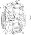
- FIG. 1 is a schematic of an example engine 100 including a throttle body 102 to control the amount of air into the engine 100.
- the engine 100 can be used in various implementations, including but not limited to mowers, utility equipment, recreational equipment, generators, welders, etc.
- a throttle drive actuator 104 is connected with the throttle body 102 to rotate a valve 106 of the throttle body 102.
- the valve 106 opens and closes to allow more or less air through the throttle body 102, e.g., in response to the operation of an accelerator and varying operating conditions of the engine 100.
- the throttle drive actuator 104 can control the tilt of the valve 106.
- the throttle drive actuator 104 includes a field magnet having at least one pair of N and S poles and an armature having at least one set of coils disposed in face-to-face confronting relation to the magnet.
- the throttle drive actuator 104 can be coupled directly to a shaft carrying the throttle valve 106, the actuator 104 being urged by a spring toward a position where the valve 106 throttles off the passage of air.
- the coils of the throttle drive actuator 104 are positioned relative to the N and S poles of the magnet such that when the coil is excited any conductor portions can act effectively to develop torque to rotate the valve 106.
- FIG. 2 is an exploded view of the example throttle drive actuator 104 that connects with the throttle body 102.
- the throttle body 102 has a cylindrical air passage 200 formed there through.
- the throttle valve 106 is supported by a rotary shaft 202.
- the throttle valve 106 can form a circular disk which closes the passage 200 or throttles the air flowing there through. Other shapes can be used.
- the rotary shaft 202 extends perpendicular to the central axis of the air passage and connect with the throttle drive actuator 104.
- the throttle valve 106 supported by the shaft 202 is placed under the influence of the drive actuator 104 which acts on the shaft 202 in such a way that the throttle valve 106 may be tilted to open and close the air passage 200.
- the throttle valve 106 is driven to rotate by the drive actuator 104 which is described in detail below, by way of the shaft 202, in such a way as to adjust the tilt of the valve for adjusting the opening of the air passage 200, hence the flow of air passing there through.
- the rotary shaft 202 is secured to the throttle valve 106 at its diametral bisector line of the circular disk of the valve so that the shaft 202 is rotated integrally with the valve 106.
- the shaft 202 is attached at its opposite end to a coupler 204 of the rotary armature 206, or any suitable bearing means, in the throttle body 104.
- An armature 206 is positioned between opposing stationary magnet 208 having N1 and S1 poles and stationary magnet 210 having N2 and S2 poles in the opposite direction of magnet 208.
- pole N1 of magnet 208 opposes pole S2 of magnet 210
- pole S1 of magnet 208 opposes pole N2 of magnet 210, as described in more detail below.
- the magnet 208 may be mounted on a plate 214 and the magnet 210 may be mounted on a plate 216.
- the armature 206 may be stationary and the magnets 208 and/or 210 moved.
- the coil of the armature 206 includes current carrying windings fed by wires 212 to induce a magnetic force which interacts with the magnet field created by magnets 208 and 210 to move the armature 206 which in turn rotates the shaft 202 to move the throttle valve 106 between open and closed positions.
- the armature 206 can include one or more magnets.
- the armature 206, the magnet 208, the magnet 210, etc. can all be enclosed in first housing portion 222 and an opposing second housing portion 224 to form a housing for the drive actuator 104.
- the first housing portion 222 can be removably attached to the throttle body 102 using fasteners 226a, 226b, e.g., screws or other fasteners. In this way the drive actuator 104 can be part of the original assembly with the throttle body 102, retrofitted to an existing throttle body 102 and/or replace a damaged drive actuator, etc.
- FIG. 3 is a schematic of the throttle drive actuator 104 assembled with the throttle body 102.
- the drive actuator 104 When assembled the drive actuator 104 includes a thin profile, e.g., less than about a third of the width of the throttle body 102, while providing a force sufficient to move the valve 106. For example, with a 1 mS pulse, a peak force of about 13.4 in-lbs can be achieved in less than about 0.7 mS.
- the drive actuator 104 can rotate the shaft 202 through about at least 75 to 80 degrees of motion in the M directions.
- the magnets 208 and 210 can be generally arc shaped and sized to provide the 75 to 80 degrees of motion. Other shapes of the magnets and degrees of range of motion can be used, e.g., up to about 180 degrees of motion.
- the magnets 208 and 210 can be constructed of one or more pieces.
- the magnet 208 and/or the magnet 210 can be constructed of two magnets such that the south poles S1 and S2 and the north poles N1 and N2 are separate magnetic pieces.
- the armature 206 may be implemented with one or more magnets instead of windings around a core.
- a return spring 218 biases the armature 206 in a de-energized position.
- a spring retaining clip 220 or other fastener holds the spring 218 so that the spring 218 can provide force to maintain the armature 206 in the determined position, e.g., to keep the valve 106 closed when no current is applied to the armature 206.
- the spring 218 can keep the valve 106 open when de-energized.
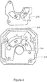
- FIG. 4 is a schematic of an example arrangement of the magnets 208 and 210.
- the orientation of the plate 216 is flipped in the direction of top to bottom so that the south pole S2 of magnet 210 aligns face-to-face with the north pole N1 of magnet 208 to create a magnetic field between the south pole S2 and north pole N1, and the north pole N2 of magnet 210 aligns face-to-face over the south pole S1 of magnet 208 to create a magnetic field between the north pole N2 and the south pole S1, in an opposite direction to the magnetic field created by south pole S2 and north pole N1.
- the armature 206 is rotatably positioned between magnet 208 and magnet 210. In a de-energized state a position of the armature 206 is maintained by the return spring 218 so that a major portion P1 of the armature 206 is positioned over north pole N1 and a minor portion P2 of the armature 206 is positioned over the south pole S1.
- Lorentz force generates the force on the two radial segments P1 and P2 of the coil windings of the armature 206 as current flows.
- the Lorentz force can include combination of electric and magnetic force on a point charge due to electromagnetic fields. Moving the armature 206 moves the shaft 202 which in turn moves the throttle valve 106, to supply more or less air into the engine 100.
- FIG. 5 is a block diagram of an example control system 500 for controlling movement of the valve 106.
- An electronic control unit 502 receives a signal representing engine requested and actual speed 504 and a signal representing throttle position 506 to control a desired position of the valve 106, e.g., via the armature 206.
- the electronic control unit 502 can be implemented with one or more control units.
- the electronic control unit 502 can determine when to send a drive signal to the drive circuit 508 which sends current to the windings of the armature 206 to determine movement of the armature 206.
- the armature 206 drives the throttle valve 106 to the desired tilt position, e.g., to let more or less air into the engine 100 based on the engine speed 504, throttle position 506, etc.
- the electronic control unit 502 feeds the drive signal to the drive circuit 508 and the drive circuit 508 energizes the coil windings of the armature 206 to produce torque, e.g., in the manner as described above.
- the magnets 208 and 210 create magnetic fields that cause the armature 206 to rotate the desired amount while overcoming the action of the return spring 218, to cause the throttle valve 106 to turn with the result that the air passage 200 is opened accordingly.
- the electronic control circuit 502 sends a signal to de-energize the armature coils. Consequently, the throttle valve 106 is tilted back to its original throttling position by the return spring 218.
- a tilt detector may be used, e.g., a potentiometer, tachogenerator, encoder or any other suitable means, which is adapted to produce and transmit a signal to the electronic control circuit 502 representing the degree of tilt of the throttle valve 106 then positioned, or the current opening of the air passage 200.
Landscapes
- Engineering & Computer Science (AREA)
- Chemical & Material Sciences (AREA)
- Combustion & Propulsion (AREA)
- Mechanical Engineering (AREA)
- General Engineering & Computer Science (AREA)
- Power Engineering (AREA)
- Physics & Mathematics (AREA)
- Electromagnetism (AREA)
- Control Of Throttle Valves Provided In The Intake System Or In The Exhaust System (AREA)
- Reciprocating, Oscillating Or Vibrating Motors (AREA)
Abstract
Description
- The systems and methods relates to engines, and more particularly to a throttle drive actuator for a throttle body.
- A motor can be used to control the tilt of a throttle valve for use in internal combustion engines. The motor can make adjustments of the throttle valve in response to the operation of the accelerator and varying operating conditions of the engine.
- According to one aspect, a throttle drive actuator for an engine includes a first magnet including a north pole and a south pole and a second magnet positioned adjacent the first magnet, the second magnet including a north pole and a south pole. The north pole of the second magnet is positioned opposite the south pole of the first magnet to create a first magnetic field, and the south pole of the second magnet is positioned opposite the north pole of the first magnet to create a second magnetic field. A direction of the second magnetic field is directed opposite a direction of the first magnetic field. An armature is positioned between the first magnet and the second magnet, the armature including windings. The armature rotates between the first magnet and the second magnet when the windings are energized by use of Lorentz force, and the armature rotates a valve of a throttle body of the engine, to open a close an air passage of the throttle body.
- Other systems, methods, features, and advantages will be or will become apparent upon examination of the following figures and detailed description. It is intended that all such additional systems, methods, features, and advantages be included within this description and be protected by the accompanying claims.
- In association with the following detailed description, reference is made to the accompanying drawings, where like numerals in different figures can refer to the same element.
-
FIG. 1 is a schematic of an example engine including a throttle body. -
FIG. 2 is an exploded view of the example drive actuator that connects with the throttle body. -
FIG. 3 is a schematic of the drive actuator assembled with the throttle body. -
FIG. 4 is a schematic of an example arrangement of the magnet and the magnet. -
FIG. 5 is a block diagram of an example control system for controlling movement of the valve. - While the disclosure may be susceptible to embodiments in different forms, there is illustrated in the drawings, and herein described in detail, one or more embodiments with the understanding that the present disclosure is to be considered an exemplification of the principles of the disclosure, and is not intended to limit the disclosure to that as illustrated and described herein. Therefore, unless otherwise noted, features disclosed herein may be combined together to form additional combinations that were not otherwise shown for purposes of brevity. It will be further appreciated that in some embodiments, one or more elements illustrated by way of example in a drawings may be eliminated and/or substituted with alternative elements within the scope of the disclosure.
-
FIG. 1 is a schematic of anexample engine 100 including athrottle body 102 to control the amount of air into theengine 100. Theengine 100 can be used in various implementations, including but not limited to mowers, utility equipment, recreational equipment, generators, welders, etc. Athrottle drive actuator 104 is connected with thethrottle body 102 to rotate avalve 106 of thethrottle body 102. Thevalve 106 opens and closes to allow more or less air through thethrottle body 102, e.g., in response to the operation of an accelerator and varying operating conditions of theengine 100. - The
throttle drive actuator 104 can control the tilt of thevalve 106. As described in more detail below, thethrottle drive actuator 104 includes a field magnet having at least one pair of N and S poles and an armature having at least one set of coils disposed in face-to-face confronting relation to the magnet. Thethrottle drive actuator 104 can be coupled directly to a shaft carrying thethrottle valve 106, theactuator 104 being urged by a spring toward a position where thevalve 106 throttles off the passage of air. The coils of thethrottle drive actuator 104 are positioned relative to the N and S poles of the magnet such that when the coil is excited any conductor portions can act effectively to develop torque to rotate thevalve 106. -
FIG. 2 is an exploded view of the examplethrottle drive actuator 104 that connects with thethrottle body 102. Thethrottle body 102 has acylindrical air passage 200 formed there through. In theair passage 200 thethrottle valve 106 is supported by arotary shaft 202. Thethrottle valve 106 can form a circular disk which closes thepassage 200 or throttles the air flowing there through. Other shapes can be used. Therotary shaft 202 extends perpendicular to the central axis of the air passage and connect with thethrottle drive actuator 104. Thethrottle valve 106 supported by theshaft 202 is placed under the influence of thedrive actuator 104 which acts on theshaft 202 in such a way that thethrottle valve 106 may be tilted to open and close theair passage 200. In operation, thethrottle valve 106 is driven to rotate by thedrive actuator 104 which is described in detail below, by way of theshaft 202, in such a way as to adjust the tilt of the valve for adjusting the opening of theair passage 200, hence the flow of air passing there through. - The
rotary shaft 202 is secured to thethrottle valve 106 at its diametral bisector line of the circular disk of the valve so that theshaft 202 is rotated integrally with thevalve 106. Theshaft 202 is attached at its opposite end to acoupler 204 of therotary armature 206, or any suitable bearing means, in thethrottle body 104. Anarmature 206 is positioned between opposingstationary magnet 208 having N1 and S1 poles andstationary magnet 210 having N2 and S2 poles in the opposite direction ofmagnet 208. For example, to create a magnetic field there between, pole N1 ofmagnet 208 opposes pole S2 ofmagnet 210, and pole S1 ofmagnet 208 opposes pole N2 ofmagnet 210, as described in more detail below. Themagnet 208 may be mounted on aplate 214 and themagnet 210 may be mounted on aplate 216. In other implementations, thearmature 206 may be stationary and themagnets 208 and/or 210 moved. - The coil of the
armature 206 includes current carrying windings fed bywires 212 to induce a magnetic force which interacts with the magnet field created bymagnets armature 206 which in turn rotates theshaft 202 to move thethrottle valve 106 between open and closed positions. In other implementations, thearmature 206 can include one or more magnets. Thearmature 206, themagnet 208, themagnet 210, etc. can all be enclosed infirst housing portion 222 and an opposingsecond housing portion 224 to form a housing for thedrive actuator 104. Thefirst housing portion 222 can be removably attached to thethrottle body 102 usingfasteners drive actuator 104 can be part of the original assembly with thethrottle body 102, retrofitted to an existingthrottle body 102 and/or replace a damaged drive actuator, etc. -
FIG. 3 is a schematic of thethrottle drive actuator 104 assembled with thethrottle body 102. When assembled thedrive actuator 104 includes a thin profile, e.g., less than about a third of the width of thethrottle body 102, while providing a force sufficient to move thevalve 106. For example, with a 1 mS pulse, a peak force of about 13.4 in-lbs can be achieved in less than about 0.7 mS. In some implementations, thedrive actuator 104 can rotate theshaft 202 through about at least 75 to 80 degrees of motion in the M directions. Themagnets - The
magnets magnet 208 and/or themagnet 210 can be constructed of two magnets such that the south poles S1 and S2 and the north poles N1 and N2 are separate magnetic pieces. In other implementations thearmature 206 may be implemented with one or more magnets instead of windings around a core. Areturn spring 218 biases thearmature 206 in a de-energized position. Aspring retaining clip 220 or other fastener holds thespring 218 so that thespring 218 can provide force to maintain thearmature 206 in the determined position, e.g., to keep thevalve 106 closed when no current is applied to thearmature 206. Alternatively, in other implementations thespring 218 can keep thevalve 106 open when de-energized. -
FIG. 4 is a schematic of an example arrangement of themagnets plate 216 is flipped in the direction of top to bottom so that the south pole S2 ofmagnet 210 aligns face-to-face with the north pole N1 ofmagnet 208 to create a magnetic field between the south pole S2 and north pole N1, and the north pole N2 ofmagnet 210 aligns face-to-face over the south pole S1 ofmagnet 208 to create a magnetic field between the north pole N2 and the south pole S1, in an opposite direction to the magnetic field created by south pole S2 and north pole N1. - The
armature 206 is rotatably positioned betweenmagnet 208 andmagnet 210. In a de-energized state a position of thearmature 206 is maintained by thereturn spring 218 so that a major portion P1 of thearmature 206 is positioned over north pole N1 and a minor portion P2 of thearmature 206 is positioned over the south pole S1. Lorentz force generates the force on the two radial segments P1 and P2 of the coil windings of thearmature 206 as current flows. The Lorentz force can include combination of electric and magnetic force on a point charge due to electromagnetic fields. Moving thearmature 206 moves theshaft 202 which in turn moves thethrottle valve 106, to supply more or less air into theengine 100. -
FIG. 5 is a block diagram of anexample control system 500 for controlling movement of thevalve 106. Anelectronic control unit 502 receives a signal representing engine requested andactual speed 504 and a signal representingthrottle position 506 to control a desired position of thevalve 106, e.g., via thearmature 206. Theelectronic control unit 502 can be implemented with one or more control units. Theelectronic control unit 502 can determine when to send a drive signal to thedrive circuit 508 which sends current to the windings of thearmature 206 to determine movement of thearmature 206. Thearmature 206 drives thethrottle valve 106 to the desired tilt position, e.g., to let more or less air into theengine 100 based on theengine speed 504,throttle position 506, etc. - When the
air passage 200 is closed by thevalve 106, which is placed under the influence of thespring 218, a fixed low amount of air is admitted through thepassage 200. Theelectronic control unit 502 feeds the drive signal to thedrive circuit 508 and thedrive circuit 508 energizes the coil windings of thearmature 206 to produce torque, e.g., in the manner as described above. Themagnets armature 206 to rotate the desired amount while overcoming the action of thereturn spring 218, to cause thethrottle valve 106 to turn with the result that theair passage 200 is opened accordingly. When it becomes desired to throttle off theair passage 200, theelectronic control circuit 502 sends a signal to de-energize the armature coils. Consequently, thethrottle valve 106 is tilted back to its original throttling position by thereturn spring 218. - In some implementations, a tilt detector may be used, e.g., a potentiometer, tachogenerator, encoder or any other suitable means, which is adapted to produce and transmit a signal to the
electronic control circuit 502 representing the degree of tilt of thethrottle valve 106 then positioned, or the current opening of theair passage 200. - While particular embodiments are illustrated in and described with respect to the drawings, it is envisioned that those skilled in the art may devise various modifications without departing from the spirit and scope of the appended claims. It will therefore be appreciated that the scope of the disclosure and the appended claims is not limited to the specific embodiments illustrated in and discussed with respect to the drawings and that modifications and other embodiments are intended to be included within the scope of the disclosure and appended drawings. Moreover, although the foregoing descriptions and the associated drawings describe example embodiments in the context of certain example combinations of elements and/or functions, it should be appreciated that different combinations of elements and/or functions may be provided by alternative embodiments without departing from the scope of the disclosure and the appended claims.
- Many modifications and other embodiments set forth herein will come to mind to one skilled in the art having the benefit of the teachings presented in the foregoing descriptions and the associated drawings. Although specific terms are employed herein, they are used in a generic and descriptive sense only and not for purposes of limitation.
- The present invention can also be described by means of the following clause:
- 1. A throttle drive actuator for an engine, comprising:
- a first magnet comprising a north pole and a south pole;
- a second magnet positioned adjacent the first magnet, the second magnet comprising a north pole and a south pole, the north pole of the second magnet positioned opposite the south pole of the first magnet to create a first magnetic field, and the south pole of the second magnet positioned opposite the north pole of the first magnet to create a second magnetic field, a direction of the second magnetic field being directed opposite a direction of the first magnetic field; and
- an armature positioned between the first magnet and the second magnet, the armature including windings, where the armature rotates between the first magnet and the second magnet when the windings are energized, where the armature rotates a valve of a throttle body of the engine, to open a close an air passage of the throttle body.
- 2. The throttle drive actuator of
clause 1, where a major portion of the armature is positioned within the first magnetic field and a minor portion of the armature is positioned within the second magnetic field. - 3. The throttle drive actuator of
clause 1, further comprising a spring connected with the armature to bias the armature to close the valve when the windings are de-energized. - 4. The throttle drive actuator of
clause 1, further including a first half of a housing and a second half of a housing to house the first magnet, the second magnet and the armature, where the first half of the housing is fastened to the throttle body. - 5. The throttle drive actuator of
clause 1, where a width of the throttle drive actuator is less than one-third a width of the throttle body. - 6. The throttle drive actuator of
clause 1, where at least one of the first magnet and the second magnet comprises at least two pieces. - 7. An engine, comprising:
- a throttle body connected with the engine, the throttle body including an air passage to provide air to the engine;
- a throttle valve disposed within the air passage to open and close the air passage;
- a rotatable shaft connected with the throttle valve;
- a rotatable armature connected with the rotatable shaft to rotate the throttle valve to open and close the air passage;
- a first magnet including a north pole and a south pole, and a second magnet including a north pole and a south pole, the first magnet positioned adjacent and opposing the second magnet to provide a first magnet field and a second magnetic field, the rotatable armature positioned between the first magnet and the second magnet; and
- an electronic control unit to send signals to energize and de-energize windings of the rotatable armature to control rotation of the rotatable armature to rotate the throttle valve.
- 8. The engine of clause 7, where the electronic control unit sends signals based on a received engine speed and throttle position.
- 9. The engine of clause 7, where a major portion of the rotatable armature is positioned within the first magnetic field and a minor portion of the armature is positioned within the second magnetic field.
- 10. The engine of clause 7, further comprising a spring connected with the armature to bias the armature to close the throttle valve when the electronic control unit de-energizes the rotatable armature.
- 11. The engine of clause 7, further including a first half of a housing and a second half of a housing to house the first magnet, the second magnet and the rotatable armature, where the first half of the housing is fastened to the throttle body.
- 12. The engine of clause 11, where a width of the housing when assembled is less than one-third a width of the throttle body.
- 13. The engine of clause 7, where at least one of the first magnet and the second magnet comprises at least two pieces.
- 14. A throttle drive actuator for an engine, comprising:
- a rotatable armature connected with a rotatable shaft to rotate a throttle valve to open and close an air passage of a throttle body;
- a first magnetic field positioned adjacent to an opposing second magnetic field, the rotatable armature positioned adjacent the first magnet field and the opposing second magnet field; and
- where the rotatable armature moves the rotatable shaft to rotate the throttle valve when the rotatable armature is energized.
- 15. The throttle drive actuator of clause 14, where a major portion of the rotatable armature is positioned within the first magnetic field and a minor portion of the armature is positioned within the second magnetic field.
- 16. The throttle drive actuator of clause 14, further comprising a spring connected with the rotatable armature to bias the rotatable armature to close the valve when the rotatable armature is de-energized.
- 17. The throttle drive actuator of clause 14, further including a first half of a housing and a second half of a housing to house the first magnet, the second magnet and the armature, where the first half of the housing is fastened to the throttle body.
- 18. The throttle drive actuator of clause 18, where a width of the housing when assembled is less than one-third a width of the throttle body.
- 19. The throttle drive actuator of clause 14, where energizing the rotatable armature is controlled by an electronic control unit.
- 20. The throttle drive actuator of clause 19, where the electronic control unit energizes and de-energized the rotatable armature based on an engine speed and a throttle position.
Claims (10)
- A throttle drive actuator for an engine, comprising:a first magnet comprising a north pole and a south pole;a second magnet positioned adjacent the first magnet, the second magnet comprising a north pole and a south pole, the north pole of the second magnet positioned opposite the south pole of the first magnet to create a first magnetic field, and the south pole of the second magnet positioned opposite the north pole of the first magnet to create a second magnetic field, a direction of the second magnetic field being directed opposite a direction of the first magnetic field; andan armature positioned between the first magnet and the second magnet, the armature including windings, where the armature rotates between the first magnet and the second magnet when the windings are energized, where the armature rotates a valve of a throttle body of the engine, to open and close an air passage of the throttle body.
- The throttle drive actuator of claim 1, where a majority of the armature is positioned within the first magnetic field and less than a majority of the armature is positioned within the second magnetic field.
- The throttle drive actuator of claim 1 or 2, further comprising a spring connected with the armature to bias the armature to close the valve when the windings are de-energized.
- The throttle drive actuator of any of claims 1-3, further including a first half of a housing and a second half of a housing to house the first magnet, the second magnet and the armature, where the first half of the housing is fastened to the throttle body.
- The throttle drive actuator of any of claims 1-4, where a width of the throttle drive actuator is less than one-third a width of the throttle body.
- The throttle drive actuator of any of claims 1-5, where at least one of the first magnet and the second magnet comprises at least two pieces.
- The throttle drive actuator of any of claims 1-6, where energizing the armature is controlled by an electronic control unit.
- The throttle drive actuator of claim 7, where the electronic control unit sends signals to energize and de-energize the windings of the armature to control rotation of the armature to rotate the valve.
- The throttle drive actuator of claim 8, where the electronic control unit sends signals based on a received engine speed.
- The throttle drive actuator of claim 8 or 9, where the electronic control unit sends signals based on a position of the valve of the throttle body.
Applications Claiming Priority (1)
| Application Number | Priority Date | Filing Date | Title |
|---|---|---|---|
| US14/876,166 US9739218B2 (en) | 2015-10-06 | 2015-10-06 | Throttle drive actuator for an engine |
Publications (2)
| Publication Number | Publication Date |
|---|---|
| EP3153683A1 true EP3153683A1 (en) | 2017-04-12 |
| EP3153683B1 EP3153683B1 (en) | 2019-05-15 |
Family
ID=57083095
Family Applications (1)
| Application Number | Title | Priority Date | Filing Date |
|---|---|---|---|
| EP16189895.2A Active EP3153683B1 (en) | 2015-10-06 | 2016-09-21 | Throttle drive actuator for an engine |
Country Status (3)
| Country | Link |
|---|---|
| US (1) | US9739218B2 (en) |
| EP (1) | EP3153683B1 (en) |
| CN (1) | CN107013344B (en) |
Families Citing this family (2)
| Publication number | Priority date | Publication date | Assignee | Title |
|---|---|---|---|---|
| US10815908B2 (en) | 2015-10-06 | 2020-10-27 | Kohler Co. | Throttle drive actuator for an engine |
| CN109083749B (en) * | 2018-07-09 | 2023-08-22 | 冯子光 | A magnetic balance air valve and an exhaust cylinder using the air valve |
Citations (5)
| Publication number | Priority date | Publication date | Assignee | Title |
|---|---|---|---|---|
| EP0154036A2 (en) * | 1984-03-09 | 1985-09-11 | Hitachi, Ltd. | Throttle valve controlling apparatus |
| US4639624A (en) * | 1984-07-27 | 1987-01-27 | Hitachi, Ltd. | Torque motor having a coil with finite turning range |
| US4651041A (en) * | 1985-04-04 | 1987-03-17 | Aisin Seiki Kabushiki Kaisha | Electric motor |
| US5168184A (en) * | 1990-10-04 | 1992-12-01 | Hitachi Metals, Ltd. | Swing-type actuator |
| US20060038456A1 (en) * | 2004-08-20 | 2006-02-23 | Dumitru Bojiuc | Monopole field electric motor generator |
Family Cites Families (41)
| Publication number | Priority date | Publication date | Assignee | Title |
|---|---|---|---|---|
| US914094A (en) | 1907-06-27 | 1909-03-02 | John T Whalen | Electrical controlling device. |
| US3459976A (en) * | 1966-07-05 | 1969-08-05 | Mohawk Data Sciences Corp | Rotary electrodynamic driver |
| US3593238A (en) | 1968-10-30 | 1971-07-13 | Nissan Motor | Throttle control unit for control system of automotive automatic transmission |
| CH514180A (en) * | 1969-06-13 | 1971-06-30 | Longines Montres Comp D | Polarized micromotor for timepiece |
| US4181288A (en) | 1978-04-05 | 1980-01-01 | Simon Bylsma | Fluid pressure regulator valve unit for a fluid delivery system |
| JPS56101026A (en) * | 1979-12-31 | 1981-08-13 | Heinzmann Gmbh Co Kg Fritz | Regulator for number of revolution of internal combustion engine |
| JPS56107119A (en) | 1980-01-30 | 1981-08-25 | Nippon Denso Co Ltd | Detecting device for rotational angle |
| JPS56150963A (en) | 1980-04-24 | 1981-11-21 | Nippon Soken Inc | Rotary driving device |
| JPS57199207A (en) | 1981-06-02 | 1982-12-07 | Nippon Soken Inc | Driving device for rotation |
| JPS59190441A (en) | 1983-04-11 | 1984-10-29 | Nissan Motor Co Ltd | Accelerator controller for vehicle |
| JPS61226533A (en) | 1985-04-01 | 1986-10-08 | Nissan Motor Co Ltd | Accelerator control device for vehicle |
| JPS61169477U (en) * | 1985-04-04 | 1986-10-21 | ||
| US5080065A (en) | 1989-10-05 | 1992-01-14 | Nippondenso Co., Ltd. | Air intake control system for an internal combustion engine |
| US5619112A (en) | 1995-02-09 | 1997-04-08 | Woodward Governor Company | Bi-directional electric torque motor and driver |
| FR2734963B1 (en) | 1995-05-31 | 1997-08-01 | Sonceboz Sa | ELECTROMAGNETIC ACTUATOR HAVING AT LEAST TWO STABLE POSITIONS BY MAGNETIC LOCKING |
| US5823165A (en) | 1996-02-23 | 1998-10-20 | Unisia Jecs Corporation | Valve actuator arrangement for internal combustion engine |
| JPH10288054A (en) | 1997-02-13 | 1998-10-27 | Denso Corp | Throttle valve control device |
| EP0917525B1 (en) * | 1997-04-28 | 2001-10-31 | Koninklijke Philips Electronics N.V. | Method of manufacturing a conductive layer on a substrate |
| US6067961A (en) | 1997-10-30 | 2000-05-30 | Denso Corporation | Throttle device for engines having shaft positioning part |
| JP3665710B2 (en) * | 1998-05-18 | 2005-06-29 | 愛三工業株式会社 | DC torque motor, drive control device using the same, and throttle valve control device |
| US6116215A (en) | 1998-07-16 | 2000-09-12 | The Barber-Colman Company | Integrated throttle valve and actuator |
| US7021603B2 (en) * | 1998-10-08 | 2006-04-04 | Wladyslaw Wygnaski | Electromagnetic actuator and integrated actuator and fluid flow control valve |
| JP3445173B2 (en) | 1998-12-11 | 2003-09-08 | ミネベア株式会社 | Actuator device with valve |
| US6541881B1 (en) | 1999-02-17 | 2003-04-01 | Eaton Corporation | Integral throttle body and torque motor |
| JP2000240474A (en) | 1999-02-24 | 2000-09-05 | Mikuni Corp | Throttle valve control device for internal combustion engine |
| US6725833B1 (en) | 1999-03-29 | 2004-04-27 | Hitachi, Ltd. | Electronically controlled throttle device |
| JP2001003770A (en) | 1999-06-16 | 2001-01-09 | Unisia Jecs Corp | Electric throttle valve device |
| JP2001123855A (en) | 1999-10-21 | 2001-05-08 | Unisia Jecs Corp | Throttle valve device |
| EA006279B1 (en) * | 2001-08-24 | 2005-10-27 | Дзе Осси Кидз Той Компани Пти Лимитед | Switchable magnetic device |
| DE10228856A1 (en) * | 2002-06-27 | 2004-01-22 | Siemens Ag | Direct drive for a throttle valve shaft in a throttle valve assembly |
| JP2004225538A (en) | 2003-01-20 | 2004-08-12 | Mitsubishi Electric Corp | Throttle valve control device |
| JP4376017B2 (en) | 2003-08-01 | 2009-12-02 | 株式会社デンソー | Electronically controlled throttle control device |
| ITBO20030530A1 (en) | 2003-09-15 | 2005-03-16 | Magneti Marelli Powertrain Spa | BUTTERFLY VALVE SERVO ASSISTED WITH A FLEXIBLE SPRING AND A SPIRAL SPRING TO ESTABLISH LIMP-HOME POSITION |
| US7137614B2 (en) | 2003-10-15 | 2006-11-21 | Aisan Kogyo Kabushiki Kaisha | Valve devices for controlling flow of intake air |
| JP4104594B2 (en) | 2004-12-22 | 2008-06-18 | 株式会社ケーヒン | Engine intake control system |
| CN2895907Y (en) * | 2006-03-06 | 2007-05-02 | 南京工业职业技术学院 | Magnetic adjustment throttle valve |
| US7946555B2 (en) | 2006-11-16 | 2011-05-24 | Aisan Kogyo Kabushiki Kaisha | Rotational angle sensors and throttle devices |
| TW201107639A (en) * | 2007-04-27 | 2011-03-01 | Edwards Japan Ltd | Plate rotating device, exhaust path opening degree changing device, exhausted device, transfer device, beam device, and gate valve |
| JP4353291B2 (en) | 2007-09-20 | 2009-10-28 | 株式会社デンソー | Valve open / close control device |
| US8257226B2 (en) | 2008-07-14 | 2012-09-04 | Honda Motor Co., Ltd. | Variable speed drivetrain for electronic throttle body |
| US9577496B2 (en) * | 2012-11-13 | 2017-02-21 | Asmo Co., Ltd. | Rotor and brushless motor with rotation position detection |
-
2015
- 2015-10-06 US US14/876,166 patent/US9739218B2/en not_active Expired - Fee Related
-
2016
- 2016-09-21 EP EP16189895.2A patent/EP3153683B1/en active Active
- 2016-09-28 CN CN201610859921.2A patent/CN107013344B/en not_active Expired - Fee Related
Patent Citations (5)
| Publication number | Priority date | Publication date | Assignee | Title |
|---|---|---|---|---|
| EP0154036A2 (en) * | 1984-03-09 | 1985-09-11 | Hitachi, Ltd. | Throttle valve controlling apparatus |
| US4639624A (en) * | 1984-07-27 | 1987-01-27 | Hitachi, Ltd. | Torque motor having a coil with finite turning range |
| US4651041A (en) * | 1985-04-04 | 1987-03-17 | Aisin Seiki Kabushiki Kaisha | Electric motor |
| US5168184A (en) * | 1990-10-04 | 1992-12-01 | Hitachi Metals, Ltd. | Swing-type actuator |
| US20060038456A1 (en) * | 2004-08-20 | 2006-02-23 | Dumitru Bojiuc | Monopole field electric motor generator |
Also Published As
| Publication number | Publication date |
|---|---|
| CN107013344B (en) | 2020-03-24 |
| CN107013344A (en) | 2017-08-04 |
| US20170096951A1 (en) | 2017-04-06 |
| EP3153683B1 (en) | 2019-05-15 |
| US9739218B2 (en) | 2017-08-22 |
Similar Documents
| Publication | Publication Date | Title |
|---|---|---|
| US12448926B2 (en) | Throttle drive actuator for an engine | |
| EP0713603B1 (en) | Device for actuating a control member | |
| EP2497185B1 (en) | Rotary single-phase electromagnetic actuator | |
| US4698535A (en) | Electric motor operated throttle valve | |
| EP0972923A2 (en) | Integrated throttle valve and actuator | |
| JP3665710B2 (en) | DC torque motor, drive control device using the same, and throttle valve control device | |
| EP3153683B1 (en) | Throttle drive actuator for an engine | |
| US6332451B1 (en) | Rotary valve actuator arrangement | |
| JP2014126553A (en) | Position detector | |
| CN107896045A (en) | Magnetic pole tooth punching formula torque-motor | |
| US11920598B2 (en) | Coolant pump for a vehicle | |
| CN105822817A (en) | Flow channel adjusting and controlling valve | |
| US5564389A (en) | Force motor for use in the fuel system of an internal combustion engine | |
| US20040155742A1 (en) | Rotary solenoid apparatus | |
| JPH11299209A (en) | Torque motor | |
| JP2001227366A (en) | Electric throttle valve device | |
| JP2000092808A (en) | Torque motor | |
| JPH0749762B2 (en) | Valve drive for internal combustion engine | |
| JPS59220063A (en) | Rotatably drive device | |
| JPH11122894A (en) | Rotary actuator | |
| JPH09329038A (en) | Rotary electromagnetic actuator | |
| JP2001182561A (en) | Throttle device | |
| JPH09261945A (en) | Governor of rotary element | |
| JPH08178107A (en) | Flow control shutoff valve drive |
Legal Events
| Date | Code | Title | Description |
|---|---|---|---|
| PUAI | Public reference made under article 153(3) epc to a published international application that has entered the european phase |
Free format text: ORIGINAL CODE: 0009012 |
|
| STAA | Information on the status of an ep patent application or granted ep patent |
Free format text: STATUS: THE APPLICATION HAS BEEN PUBLISHED |
|
| AK | Designated contracting states |
Kind code of ref document: A1 Designated state(s): AL AT BE BG CH CY CZ DE DK EE ES FI FR GB GR HR HU IE IS IT LI LT LU LV MC MK MT NL NO PL PT RO RS SE SI SK SM TR |
|
| AX | Request for extension of the european patent |
Extension state: BA ME |
|
| STAA | Information on the status of an ep patent application or granted ep patent |
Free format text: STATUS: REQUEST FOR EXAMINATION WAS MADE |
|
| 17P | Request for examination filed |
Effective date: 20171011 |
|
| RBV | Designated contracting states (corrected) |
Designated state(s): AL AT BE BG CH CY CZ DE DK EE ES FI FR GB GR HR HU IE IS IT LI LT LU LV MC MK MT NL NO PL PT RO RS SE SI SK SM TR |
|
| STAA | Information on the status of an ep patent application or granted ep patent |
Free format text: STATUS: EXAMINATION IS IN PROGRESS |
|
| 17Q | First examination report despatched |
Effective date: 20180327 |
|
| REG | Reference to a national code |
Ref country code: DE Ref legal event code: R079 Ref document number: 602016013936 Country of ref document: DE Free format text: PREVIOUS MAIN CLASS: F02D0009020000 Ipc: F02M0035100000 |
|
| RIC1 | Information provided on ipc code assigned before grant |
Ipc: F02D 41/00 20060101ALI20181026BHEP Ipc: H02K 41/035 20060101ALI20181026BHEP Ipc: F02D 9/10 20060101ALI20181026BHEP Ipc: F02M 35/10 20060101AFI20181026BHEP Ipc: H02K 21/14 20060101ALI20181026BHEP Ipc: F02D 9/02 20060101ALI20181026BHEP Ipc: F02D 11/10 20060101ALI20181026BHEP |
|
| GRAP | Despatch of communication of intention to grant a patent |
Free format text: ORIGINAL CODE: EPIDOSNIGR1 |
|
| STAA | Information on the status of an ep patent application or granted ep patent |
Free format text: STATUS: GRANT OF PATENT IS INTENDED |
|
| INTG | Intention to grant announced |
Effective date: 20181212 |
|
| GRAS | Grant fee paid |
Free format text: ORIGINAL CODE: EPIDOSNIGR3 |
|
| GRAA | (expected) grant |
Free format text: ORIGINAL CODE: 0009210 |
|
| STAA | Information on the status of an ep patent application or granted ep patent |
Free format text: STATUS: THE PATENT HAS BEEN GRANTED |
|
| AK | Designated contracting states |
Kind code of ref document: B1 Designated state(s): AL AT BE BG CH CY CZ DE DK EE ES FI FR GB GR HR HU IE IS IT LI LT LU LV MC MK MT NL NO PL PT RO RS SE SI SK SM TR |
|
| REG | Reference to a national code |
Ref country code: CH Ref legal event code: EP |
|
| REG | Reference to a national code |
Ref country code: DE Ref legal event code: R096 Ref document number: 602016013936 Country of ref document: DE |
|
| REG | Reference to a national code |
Ref country code: IE Ref legal event code: FG4D |
|
| REG | Reference to a national code |
Ref country code: NL Ref legal event code: MP Effective date: 20190515 |
|
| REG | Reference to a national code |
Ref country code: LT Ref legal event code: MG4D |
|
| PG25 | Lapsed in a contracting state [announced via postgrant information from national office to epo] |
Ref country code: AL Free format text: LAPSE BECAUSE OF FAILURE TO SUBMIT A TRANSLATION OF THE DESCRIPTION OR TO PAY THE FEE WITHIN THE PRESCRIBED TIME-LIMIT Effective date: 20190515 Ref country code: PT Free format text: LAPSE BECAUSE OF FAILURE TO SUBMIT A TRANSLATION OF THE DESCRIPTION OR TO PAY THE FEE WITHIN THE PRESCRIBED TIME-LIMIT Effective date: 20190915 Ref country code: SE Free format text: LAPSE BECAUSE OF FAILURE TO SUBMIT A TRANSLATION OF THE DESCRIPTION OR TO PAY THE FEE WITHIN THE PRESCRIBED TIME-LIMIT Effective date: 20190515 Ref country code: FI Free format text: LAPSE BECAUSE OF FAILURE TO SUBMIT A TRANSLATION OF THE DESCRIPTION OR TO PAY THE FEE WITHIN THE PRESCRIBED TIME-LIMIT Effective date: 20190515 Ref country code: NO Free format text: LAPSE BECAUSE OF FAILURE TO SUBMIT A TRANSLATION OF THE DESCRIPTION OR TO PAY THE FEE WITHIN THE PRESCRIBED TIME-LIMIT Effective date: 20190815 Ref country code: HR Free format text: LAPSE BECAUSE OF FAILURE TO SUBMIT A TRANSLATION OF THE DESCRIPTION OR TO PAY THE FEE WITHIN THE PRESCRIBED TIME-LIMIT Effective date: 20190515 Ref country code: NL Free format text: LAPSE BECAUSE OF FAILURE TO SUBMIT A TRANSLATION OF THE DESCRIPTION OR TO PAY THE FEE WITHIN THE PRESCRIBED TIME-LIMIT Effective date: 20190515 Ref country code: ES Free format text: LAPSE BECAUSE OF FAILURE TO SUBMIT A TRANSLATION OF THE DESCRIPTION OR TO PAY THE FEE WITHIN THE PRESCRIBED TIME-LIMIT Effective date: 20190515 Ref country code: LT Free format text: LAPSE BECAUSE OF FAILURE TO SUBMIT A TRANSLATION OF THE DESCRIPTION OR TO PAY THE FEE WITHIN THE PRESCRIBED TIME-LIMIT Effective date: 20190515 |
|
| PG25 | Lapsed in a contracting state [announced via postgrant information from national office to epo] |
Ref country code: RS Free format text: LAPSE BECAUSE OF FAILURE TO SUBMIT A TRANSLATION OF THE DESCRIPTION OR TO PAY THE FEE WITHIN THE PRESCRIBED TIME-LIMIT Effective date: 20190515 Ref country code: LV Free format text: LAPSE BECAUSE OF FAILURE TO SUBMIT A TRANSLATION OF THE DESCRIPTION OR TO PAY THE FEE WITHIN THE PRESCRIBED TIME-LIMIT Effective date: 20190515 Ref country code: BG Free format text: LAPSE BECAUSE OF FAILURE TO SUBMIT A TRANSLATION OF THE DESCRIPTION OR TO PAY THE FEE WITHIN THE PRESCRIBED TIME-LIMIT Effective date: 20190815 Ref country code: GR Free format text: LAPSE BECAUSE OF FAILURE TO SUBMIT A TRANSLATION OF THE DESCRIPTION OR TO PAY THE FEE WITHIN THE PRESCRIBED TIME-LIMIT Effective date: 20190816 |
|
| REG | Reference to a national code |
Ref country code: AT Ref legal event code: MK05 Ref document number: 1133725 Country of ref document: AT Kind code of ref document: T Effective date: 20190515 |
|
| PG25 | Lapsed in a contracting state [announced via postgrant information from national office to epo] |
Ref country code: DK Free format text: LAPSE BECAUSE OF FAILURE TO SUBMIT A TRANSLATION OF THE DESCRIPTION OR TO PAY THE FEE WITHIN THE PRESCRIBED TIME-LIMIT Effective date: 20190515 Ref country code: EE Free format text: LAPSE BECAUSE OF FAILURE TO SUBMIT A TRANSLATION OF THE DESCRIPTION OR TO PAY THE FEE WITHIN THE PRESCRIBED TIME-LIMIT Effective date: 20190515 Ref country code: AT Free format text: LAPSE BECAUSE OF FAILURE TO SUBMIT A TRANSLATION OF THE DESCRIPTION OR TO PAY THE FEE WITHIN THE PRESCRIBED TIME-LIMIT Effective date: 20190515 Ref country code: SK Free format text: LAPSE BECAUSE OF FAILURE TO SUBMIT A TRANSLATION OF THE DESCRIPTION OR TO PAY THE FEE WITHIN THE PRESCRIBED TIME-LIMIT Effective date: 20190515 Ref country code: CZ Free format text: LAPSE BECAUSE OF FAILURE TO SUBMIT A TRANSLATION OF THE DESCRIPTION OR TO PAY THE FEE WITHIN THE PRESCRIBED TIME-LIMIT Effective date: 20190515 |
|
| REG | Reference to a national code |
Ref country code: DE Ref legal event code: R097 Ref document number: 602016013936 Country of ref document: DE |
|
| PG25 | Lapsed in a contracting state [announced via postgrant information from national office to epo] |
Ref country code: IT Free format text: LAPSE BECAUSE OF FAILURE TO SUBMIT A TRANSLATION OF THE DESCRIPTION OR TO PAY THE FEE WITHIN THE PRESCRIBED TIME-LIMIT Effective date: 20190515 Ref country code: SM Free format text: LAPSE BECAUSE OF FAILURE TO SUBMIT A TRANSLATION OF THE DESCRIPTION OR TO PAY THE FEE WITHIN THE PRESCRIBED TIME-LIMIT Effective date: 20190515 |
|
| PLBE | No opposition filed within time limit |
Free format text: ORIGINAL CODE: 0009261 |
|
| STAA | Information on the status of an ep patent application or granted ep patent |
Free format text: STATUS: NO OPPOSITION FILED WITHIN TIME LIMIT |
|
| PG25 | Lapsed in a contracting state [announced via postgrant information from national office to epo] |
Ref country code: TR Free format text: LAPSE BECAUSE OF FAILURE TO SUBMIT A TRANSLATION OF THE DESCRIPTION OR TO PAY THE FEE WITHIN THE PRESCRIBED TIME-LIMIT Effective date: 20190515 |
|
| 26N | No opposition filed |
Effective date: 20200218 |
|
| PG25 | Lapsed in a contracting state [announced via postgrant information from national office to epo] |
Ref country code: PL Free format text: LAPSE BECAUSE OF FAILURE TO SUBMIT A TRANSLATION OF THE DESCRIPTION OR TO PAY THE FEE WITHIN THE PRESCRIBED TIME-LIMIT Effective date: 20190515 |
|
| PG25 | Lapsed in a contracting state [announced via postgrant information from national office to epo] |
Ref country code: MC Free format text: LAPSE BECAUSE OF FAILURE TO SUBMIT A TRANSLATION OF THE DESCRIPTION OR TO PAY THE FEE WITHIN THE PRESCRIBED TIME-LIMIT Effective date: 20190515 Ref country code: SI Free format text: LAPSE BECAUSE OF FAILURE TO SUBMIT A TRANSLATION OF THE DESCRIPTION OR TO PAY THE FEE WITHIN THE PRESCRIBED TIME-LIMIT Effective date: 20190515 |
|
| REG | Reference to a national code |
Ref country code: CH Ref legal event code: PL |
|
| PG25 | Lapsed in a contracting state [announced via postgrant information from national office to epo] |
Ref country code: CH Free format text: LAPSE BECAUSE OF NON-PAYMENT OF DUE FEES Effective date: 20190930 Ref country code: LU Free format text: LAPSE BECAUSE OF NON-PAYMENT OF DUE FEES Effective date: 20190921 Ref country code: IE Free format text: LAPSE BECAUSE OF NON-PAYMENT OF DUE FEES Effective date: 20190921 Ref country code: LI Free format text: LAPSE BECAUSE OF NON-PAYMENT OF DUE FEES Effective date: 20190930 |
|
| REG | Reference to a national code |
Ref country code: BE Ref legal event code: MM Effective date: 20190930 |
|
| PG25 | Lapsed in a contracting state [announced via postgrant information from national office to epo] |
Ref country code: BE Free format text: LAPSE BECAUSE OF NON-PAYMENT OF DUE FEES Effective date: 20190930 |
|
| PG25 | Lapsed in a contracting state [announced via postgrant information from national office to epo] |
Ref country code: FR Free format text: LAPSE BECAUSE OF NON-PAYMENT OF DUE FEES Effective date: 20190930 |
|
| PG25 | Lapsed in a contracting state [announced via postgrant information from national office to epo] |
Ref country code: RO Free format text: LAPSE BECAUSE OF FAILURE TO SUBMIT A TRANSLATION OF THE DESCRIPTION OR TO PAY THE FEE WITHIN THE PRESCRIBED TIME-LIMIT Effective date: 20190515 |
|
| GBPC | Gb: european patent ceased through non-payment of renewal fee |
Effective date: 20200921 |
|
| PG25 | Lapsed in a contracting state [announced via postgrant information from national office to epo] |
Ref country code: CY Free format text: LAPSE BECAUSE OF FAILURE TO SUBMIT A TRANSLATION OF THE DESCRIPTION OR TO PAY THE FEE WITHIN THE PRESCRIBED TIME-LIMIT Effective date: 20190515 |
|
| PG25 | Lapsed in a contracting state [announced via postgrant information from national office to epo] |
Ref country code: IS Free format text: LAPSE BECAUSE OF FAILURE TO SUBMIT A TRANSLATION OF THE DESCRIPTION OR TO PAY THE FEE WITHIN THE PRESCRIBED TIME-LIMIT Effective date: 20190915 |
|
| PG25 | Lapsed in a contracting state [announced via postgrant information from national office to epo] |
Ref country code: MT Free format text: LAPSE BECAUSE OF FAILURE TO SUBMIT A TRANSLATION OF THE DESCRIPTION OR TO PAY THE FEE WITHIN THE PRESCRIBED TIME-LIMIT Effective date: 20190515 Ref country code: HU Free format text: LAPSE BECAUSE OF FAILURE TO SUBMIT A TRANSLATION OF THE DESCRIPTION OR TO PAY THE FEE WITHIN THE PRESCRIBED TIME-LIMIT; INVALID AB INITIO Effective date: 20160921 |
|
| PG25 | Lapsed in a contracting state [announced via postgrant information from national office to epo] |
Ref country code: GB Free format text: LAPSE BECAUSE OF NON-PAYMENT OF DUE FEES Effective date: 20200921 |
|
| PG25 | Lapsed in a contracting state [announced via postgrant information from national office to epo] |
Ref country code: MK Free format text: LAPSE BECAUSE OF FAILURE TO SUBMIT A TRANSLATION OF THE DESCRIPTION OR TO PAY THE FEE WITHIN THE PRESCRIBED TIME-LIMIT Effective date: 20190515 |
|
| P01 | Opt-out of the competence of the unified patent court (upc) registered |
Effective date: 20230707 |
|
| REG | Reference to a national code |
Ref country code: DE Ref legal event code: R081 Ref document number: 602016013936 Country of ref document: DE Owner name: DISCOVERY ENERGY, LLC, KOHLER, US Free format text: FORMER OWNER: KOHLER CO., KOHLER, WIS., US |
|
| PGFP | Annual fee paid to national office [announced via postgrant information from national office to epo] |
Ref country code: DE Payment date: 20240930 Year of fee payment: 9 |