EP3153610A1 - Ansteuereinrichtung - Google Patents
Ansteuereinrichtung Download PDFInfo
- Publication number
- EP3153610A1 EP3153610A1 EP16190844.7A EP16190844A EP3153610A1 EP 3153610 A1 EP3153610 A1 EP 3153610A1 EP 16190844 A EP16190844 A EP 16190844A EP 3153610 A1 EP3153610 A1 EP 3153610A1
- Authority
- EP
- European Patent Office
- Prior art keywords
- drive
- electric motor
- rotation
- control module
- drives
- Prior art date
- Legal status (The legal status is an assumption and is not a legal conclusion. Google has not performed a legal analysis and makes no representation as to the accuracy of the status listed.)
- Granted
Links
Images


Classifications
-
- D—TEXTILES; PAPER
- D01—NATURAL OR MAN-MADE THREADS OR FIBRES; SPINNING
- D01H—SPINNING OR TWISTING
- D01H1/00—Spinning or twisting machines in which the product is wound-up continuously
- D01H1/14—Details
- D01H1/20—Driving or stopping arrangements
- D01H1/32—Driving or stopping arrangements for complete machines
-
- B—PERFORMING OPERATIONS; TRANSPORTING
- B65—CONVEYING; PACKING; STORING; HANDLING THIN OR FILAMENTARY MATERIAL
- B65H—HANDLING THIN OR FILAMENTARY MATERIAL, e.g. SHEETS, WEBS, CABLES
- B65H54/00—Winding, coiling, or depositing filamentary material
- B65H54/70—Other constructional features of yarn-winding machines
- B65H54/74—Driving arrangements
-
- B—PERFORMING OPERATIONS; TRANSPORTING
- B65—CONVEYING; PACKING; STORING; HANDLING THIN OR FILAMENTARY MATERIAL
- B65H—HANDLING THIN OR FILAMENTARY MATERIAL, e.g. SHEETS, WEBS, CABLES
- B65H63/00—Warning or safety devices, e.g. automatic fault detectors, stop-motions ; Quality control of the package
-
- D—TEXTILES; PAPER
- D02—YARNS; MECHANICAL FINISHING OF YARNS OR ROPES; WARPING OR BEAMING
- D02J—FINISHING OR DRESSING OF FILAMENTS, YARNS, THREADS, CORDS, ROPES OR THE LIKE
- D02J1/00—Modifying the structure or properties resulting from a particular structure; Modifying, retaining, or restoring the physical form or cross-sectional shape, e.g. by use of dies or squeeze rollers
- D02J1/22—Stretching or tensioning, shrinking or relaxing, e.g. by use of overfeed and underfeed apparatus, or preventing stretch
-
- H—ELECTRICITY
- H02—GENERATION; CONVERSION OR DISTRIBUTION OF ELECTRIC POWER
- H02P—CONTROL OR REGULATION OF ELECTRIC MOTORS, ELECTRIC GENERATORS OR DYNAMO-ELECTRIC CONVERTERS; CONTROLLING TRANSFORMERS, REACTORS OR CHOKE COILS
- H02P3/00—Arrangements for stopping or slowing electric motors, generators, or dynamo-electric converters
- H02P3/06—Arrangements for stopping or slowing electric motors, generators, or dynamo-electric converters for stopping or slowing an individual dynamo-electric motor or dynamo-electric converter
- H02P3/18—Arrangements for stopping or slowing electric motors, generators, or dynamo-electric converters for stopping or slowing an individual dynamo-electric motor or dynamo-electric converter for stopping or slowing an AC motor
-
- H—ELECTRICITY
- H02—GENERATION; CONVERSION OR DISTRIBUTION OF ELECTRIC POWER
- H02P—CONTROL OR REGULATION OF ELECTRIC MOTORS, ELECTRIC GENERATORS OR DYNAMO-ELECTRIC CONVERTERS; CONTROLLING TRANSFORMERS, REACTORS OR CHOKE COILS
- H02P6/00—Arrangements for controlling synchronous motors or other dynamo-electric motors using electronic commutation dependent on the rotor position; Electronic commutators therefor
- H02P6/14—Electronic commutators
- H02P6/16—Circuit arrangements for detecting position
- H02P6/18—Circuit arrangements for detecting position without separate position detecting elements
- H02P6/182—Circuit arrangements for detecting position without separate position detecting elements using back-emf in windings
-
- H—ELECTRICITY
- H02—GENERATION; CONVERSION OR DISTRIBUTION OF ELECTRIC POWER
- H02P—CONTROL OR REGULATION OF ELECTRIC MOTORS, ELECTRIC GENERATORS OR DYNAMO-ELECTRIC CONVERTERS; CONTROLLING TRANSFORMERS, REACTORS OR CHOKE COILS
- H02P6/00—Arrangements for controlling synchronous motors or other dynamo-electric motors using electronic commutation dependent on the rotor position; Electronic commutators therefor
- H02P6/14—Electronic commutators
- H02P6/16—Circuit arrangements for detecting position
- H02P6/18—Circuit arrangements for detecting position without separate position detecting elements
- H02P6/188—Circuit arrangements for detecting position without separate position detecting elements using the voltage difference between the windings
-
- B—PERFORMING OPERATIONS; TRANSPORTING
- B65—CONVEYING; PACKING; STORING; HANDLING THIN OR FILAMENTARY MATERIAL
- B65H—HANDLING THIN OR FILAMENTARY MATERIAL, e.g. SHEETS, WEBS, CABLES
- B65H2701/00—Handled material; Storage means
- B65H2701/30—Handled filamentary material
- B65H2701/31—Textiles threads or artificial strands of filaments
Definitions
- the invention relates to a drive device for textile machine drive arrangement comprising at least one drive train with a plurality of drives and with a control module for operating the drives, wherein each drive comprises an electric motor with a plurality of motor winding lines, acting as an actuator for the drive inverter and the electric motor associated controller for driving the electric motor, and comprising a machine control unit, which is data-technically connected to the control module of the at least one drive train, wherein at least a first data bus line is provided for connecting the machine control unit with the control module and wherein the at least one drive train has a further data bus, via which the control module of the drive train is connected in terms of data technology with the controllers of the drives.
- a drive arrangement for a textile machine usually has a plurality of drive trains which each provide a plurality of drives and a control module for actuating the drives.
- a machine control unit is provided which, in terms of data technology, with the control modules the various drive trains cooperates.
- the data connection is usually realized via a data bus.
- the processing of a textile takes place across powertrains, with drives working together on the textile.
- the first drives of the drive trains act together on a first textile.
- the second drives of the drive trains act on a second textile.
- a number of textiles corresponding to the number of drives per drive train is processed in parallel and simultaneously in the textile machine.
- the drives In order to be able to process the textiles independently of one another, the drives must be controlled independently of the drive train and independently and, in particular, individually put into operation or stopped. In addition, the drives for coding their mounting position in the respective drive train and for assignment to the various drive trains must be individually identified or identified. In each case, this is done via typically mechanically trained controls, which are to be provided for each drive. By providing the plurality of operating elements, the drive arrangement and the associated drive device are correspondingly complicated and expensive.
- the object of the present invention is therefore to specify a particularly cost-effective and flexibly usable drive device for a textile machine drive arrangement.
- the invention in conjunction with the preamble of claim 1, characterized in that the motor winding lines of each drive is associated with a detector assembly which is adapted to detect a direction of rotation and a rotation angle of a rotor of the electric motor that the motor winding lines continue to the Inverter comprehensive associated control circuit, which is designed for selectively driving the electric motor and imposing a counteracting the rotation of the electric motor holding torque and that the controller of the electric motor and / or the control module of the drive trains and / or the higher-level machine control unit is designed to cooperate with the Detector arrangement and the drive circuit such that depending on the direction of rotation and the rotation angle, a local rotational binding occurs.
- control device in the control device according to the invention can be dispensed with controls or that the number of controls can be reduced. In this respect, costs can be saved.
- the drive device can be used in particular with electric motors realized in asynchronous or synchronous construction.
- the drives themselves are used as input means.
- a user presses a rotational movement out of the stationary state via the shaft of the electric motor or a rotation body (galette) fixed to the shaft.
- the rotational movement is evaluated with respect to the direction of rotation and the angle of rotation of the detector arrangement of the drive device.
- the drive circuit of the drive device is used to make the rotation of the shaft or the rotor haptic perceptible. It is insofar intended within a shaft rotation difficult and smooth angular ranges depict, which are perceived by the user as a detent.
- information about the installation position of the drive or instructions for the startup or the operating parameters of the drive can be entered by the user according to a predetermined scheme.
- rotation of the rotor about a clockwise detent indicates a first rank within a driveline.
- a second number in the drive train is identified by a rotational movement about two notches clockwise and so on. For example, by a rotation of the rotor by two notches in the counterclockwise direction of the drive can be turned on. On separate controls can be waived so far.
- a magnetic field is generated, which counteracts a rotation of the electric motor or a shaft and the rotor held there, at least when stopped as a holding torque.
- the drive circuit may be realized in the manner of a short circuit.
- the short circuit usually provides a plurality of switching elements, which are connected via a control line to the controller of the drive, the control module of the drive train or the machine control unit and operated by them.
- transistors are provided as switching elements.
- at least six switching elements are installed so that each motor winding line are assigned two switching elements.
- the realization of the drive circuit as a short circuit is provided in particular for synchronous motors.
- the synchronous motors can be realized, for example, as a permanent magnet synchronous motors or brush-less DC motors.
- the detector arrangement of the drive device can be realized, for example, in the manner of a detector circuit.
- the detector circuit comprises two and for example three sensor lines, which are provided between two or three motor winding lines and each provide a current blocking element.
- the current blocking element is designed, for example, in the manner of a diode.
- a plurality of likewise connected in series resistors is provided in series with the current blocking element in each sensor line.
- two resistors are connected in series with the current blocking element in each sensor line.
- a signal tap is realized, from which a signal line is guided to the controller of the electric motor.
- the signal line becomes an input of an analog-to-digital converter the controller so that the signal on the direction of rotation and the angle of rotation can be determined and processed in digitized form by the controller.
- the detector arrangement can be designed for measuring and evaluating the motor currents in the motor winding lines.
- the direction of rotation can be determined.
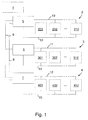
- a textile machine drive arrangement comprised an engine control unit 1 and a plurality of drive trains 2, 3, 4.
- the drive trains 2, 3, 4 each have, for example, twelve drives 201, 202, 212, 301, 302, 312, 401, 402, 412.
- first drive 201, 301, 401, a second drive 202, 302, 402 and a twelfth drive 212, 312, 412 are shown for each drive train 2, 3, 4.
- each drive train 2, 3, 4, a control module 5, 6, 7, which with the drives 201, 202, 212, 301, 302, 312, 401, 402, 412 of the respective drive train 2, 3, 4 cooperates and serves to operate the drives 201, 202, 212, 301, 302, 312, 401, 402, 412.
- the control module 5, 6, 7 are connected via a first data bus 8 data technology with the machine control unit 1.
- a second data bus 9 is provided between the control modules 5, 6, 7. While the first data bus line 8 is used for communication from the machine control unit 1 to the control modules 5, 6, 7 and back, the second data bus line 9 in particular serves for the communication between the various control modules 5, 6, 7.
- the control modules 5, 6, 7 each have a further data bus line 10, 11, 12 with the drives 201, 202, 212, 301, 302, 312, 401, 402, 412 of the respective drive train 2 , 3, 4 connected by data technology.
- an electrical supply line 13, 14, 15 is provided for each drive train 2, 3, 4, which drives 201, 202, 212, 301, 302, 312, 401, 402, 412 of the associated control modules 5, 6, 7 be energized.
- Fig. 2 shows, by way of example for the first drive train 2, that each drive 201, 202, 212 has an electric motor 19, 20, 21 as well as a controller 16, 17, 18 assigned to the electric motor 19, 20, 21.
- an electric motor for example, an asynchronous and synchronous motor is provided. In particular, it may be provided to form a synchronous motor in the manner of a permanent magnet synchronous motor or a brushless DC motor.
- the control device comprises the machine control unit 1 and the control modules 5, 6, 7. Furthermore, the control components associated with the respective drives 201, 202, 212, 301, 302, 312, 401, 402, 412 are part of the control device.
- Fig. 3 shows exemplary of the electric motor 19 of the first drive 201 of the first drive train 2 as part of the control device according to the invention realized control components.
- a detector circuit 25 and, on the other hand, a short circuit 36 are provided. In each case, the detector circuit 25 and the short circuit 36 act on the total of three motor winding lines 22, 23, 24 of the electric motor 19. In this case, the detector circuit 25 provides two sensor lines 26, 27 before. The sensor lines 26, 27 are provided parallel to each other between two motor windings 23, 24.
- the sensor line 26, 27 comprise a diode 28, 29 as a current blocking element and in Row for this purpose connects two resistors 30, 31, 32, 33. Between the first resistor 30 and the second resistor 31 of the first sensor line 26, a first signal tap is realized, from which a first signal line 34 to an input of an analog-to-digital converter of the controller 16 of the first drive 201 is guided. In an analogous manner, the second sensor line 27 between the first resistor 32 and the second resistor 33 before a signal tap, from which a second signal line 35 is guided to the analog-to-digital converter of the controller 16. Via the detector circuit 25, a direction of rotation of the electric motor 19 can be determined in cooperation with the diodes 28, 29 and the resistors 30, 31, 32, 33, and an angle of rotation of the electric motor 19 can be detected in terms of amount.
- the short circuit 36 comprises a total of six transistors 37, 38, 39, 40, 41, 42 as switching elements.
- the transistors are assigned in pairs to the three motor windings 22, 23, 24 so that individual or all motor winding lines 22, 23, 24 can be selectively short-circuited.
- the transistors have a control input, which is connected via a control line 43, 44, 45, 46, 47, 48 with the controller 16 of the first drive 201.
- the controller 16 controls so far the switching elements 37, 38, 39, 40, 41, 42 and closes depending on the switching state, the motor winding lines 22, 23, 24 briefly.
- the detector circuit 25 provides three the motor winding lines 22, 23, 24, mutually parallel sensor lines.
- the three sensor lines are formed as described above with a diode as a current blocking element and a plurality of additionally connected in series resistors.
- Each motor winding line 22, 23, 24 in this case is assigned a sensor line.
- three sensor lines are led to the input of the analog-to-digital converter of the controller 16 of the respective drive of the signal taps formed between the resistors.
- the detector arrangement provides measuring means for detecting the direction of rotation of the electric motor 19, 20, 21.
- the motor currents in the motor winding lines 22, 23, 24 are detected and evaluated by measurement.
- the transistors 37, 38, 39, 40, 41, 42 are provided for short-circuiting the motor winding lines 22, 23, 24 at standstill of the electric motor 19, 20, 21.
- the rotation of the shaft of the electric motor 19, 20, 21 is in this case from the beginning inhibited.
Landscapes
- Engineering & Computer Science (AREA)
- Power Engineering (AREA)
- Textile Engineering (AREA)
- Quality & Reliability (AREA)
- Mechanical Engineering (AREA)
- Control Of Ac Motors In General (AREA)
- Control Of Motors That Do Not Use Commutators (AREA)
Abstract
Description
- Die Erfindung betrifft eine Ansteuereinrichtung für Textilmaschinen-Antriebsanordnung umfassend wenigstens einen Antriebsstrang mit einer Mehrzahl von Antrieben und mit einem Steuermodul zum Betreiben der Antriebe, wobei jeder Antrieb einen Elektromotor mit einer Mehrzahl von Motorwicklungsleitungen, einen als Stellglied für den Antrieb wirkenden Wechselrichter und einen dem Elektromotor zugeordneten Kontroller zum Ansteuern des Elektromotors aufweist, und umfassend eine Maschinensteuereinheit, welche mit dem Steuermodul des wenigstens einem Antriebsstrangs datentechnisch verbunden ist, wobei wenigstens eine erste Datenbusleitung vorgesehen ist zum Verbinden der Maschinensteuereinheit mit den Steuermodul und wobei der wenigstens eine Antriebsstrang eine weitere Datenbusleitung aufweist, über die das Steuermodul des Antriebsstrangs mit den Kontrollern der Antriebe datentechnisch verbunden ist.
- Eine Antriebsanordnung für eine Textilmaschine verfügt üblicherweise über eine Mehrzahl von Antriebssträngen, welche jeweils eine Mehrzahl von Antrieben und ein Steuermodul zum Betätigen der Antriebe vorsehen. Zusätzlich ist eine Maschinensteuereinheit vorgesehen, welche datentechnisch mit den Steuermodulen der verschiedenen Antriebsstränge zusammenwirkt. Die datentechnische Verbindung ist in der Regel über eine Datenbusleitung realisiert. Die Bearbeitung eines Textils erfolgt antriebsstrangübergreifend, indem Antriebe gemeinsam auf das Textil einwirken. Beispielsweise wirken die ersten Antriebe der Antriebsstränge gemeinsam auf ein erstes Textil ein. In analoger Weise wirken die zweiten Antriebe der Antriebsstränge auf ein zweites Textil ein. Insgesamt wird so in der Textilmaschine eine zu der Anzahl der Antriebe je Antriebsstrang korrespondierende Anzahl von Textilien parallel und gleichzeitig bearbeitet.
- Um die Textilien nunmehr unabhängig voneinander bearbeiten zu können, müssen die Antriebe antriebsstrangübergreifend und unabhängig angesteuert und insbesondere individuell in Betrieb genommen beziehungsweise gestoppt werden. Zusätzlich müssen die Antriebe zur Kodierung ihrer Einbauposition in dem jeweiligen Antriebsstrang und zur Zuordnung zu den verschiedenen Antriebssträngen einzeln identifiziert beziehungsweise kenntlich gemacht werden. Jeweils erfolgt dies über typischerweise mechanisch ausgebildete Bedienelemente, welche für jeden einzelnen Antrieb vorzusehen sind. Durch das Vorsehen der Vielzahl von Bedienelemente sind die Antriebsanordnung und die zugeordnete Ansteuereinrichtung entsprechend aufwendig und teuer.
- Aufgabe der vorliegenden Erfindung ist es insofern, eine besonders kostengünstige und flexibel verwendbare Ansteuereinrichtung für eine Textilmaschinen-Antriebsanordnung anzugeben.
- Zur Lösung der Aufgabe ist die Erfindung in Verbindung mit dem Oberbegriff des Patentanspruchs 1 dadurch gekennzeichnet, dass den Motorwicklungsleitungen eines jeden Antriebs eine Detektoranordnung zugeordnet ist, welche ausgebildet ist zum Detektieren einer Drehrichtung und eines Drehwinkels eines Rotors des Elektromotor, dass den Motorwicklungsleitungen weiterhin eine dem Wechselrichter umfassende Ansteuerschaltung zugeordnet, welche ausgebildet ist zum wahlweisen Antreiben des Elektromotors und zum Aufprägen eines der Rotation des Elektromotors entgegenwirkenden Haltemoments und dass der Kontroller des Elektromotors und/oder das Steuermodul der Antriebsstränge und/oder die übergeordnete Maschinensteuereinheit ausgebildet ist zum Zusammenwirken mit der Detektoranordnung und der Ansteuerschaltung derart, dass in Abhängigkeit der Drehrichtung und des Drehwinkels eine lokale Rotationsschwergängigkeit auftritt. Der besondere Vorteil der Erfindung besteht darin, dass bei der erfindungsgemäßen Ansteuereinrichtung auf Bedienelemente verzichtet werden kann oder dass die Anzahl an Bedienelementen reduziert werden kann. Es können insofern Kosten eingespart werden. Die Ansteuereinrichtung kann insbesondere mit in Asynchronbeziehungsweise Synchronbauweise realisierten Elektromotoren zur Anwendung kommen.
- Anstelle der Bedienelemente werden die Antriebe selbst als Eingabemittel verwendet. Es ist hierbei so, dass ein Benutzer über die Welle des Elektromotors oder einen an der Welle festgelegten Rotationskörper (Galette) aus dem stehenden Zustand heraus eine Rotationsbewegung aufprägt. Die Rotationsbewegung wird mit den in Bezug auf die Drehrichtung und den Drehwinkel von der Detektoranordnung der Ansteuereinrichtung ausgewertet. Überdies dient die Ansteuerschaltung der Ansteuereinrichtung dazu, die Rotation der Welle beziehungsweise des Rotors haptisch wahrnehmbar zu gestalten. Es ist insofern vorgesehen innerhalb einer Wellenumdrehung schwergängige und leichtgängige Winkelbereiche abzubilden, welche vom Benutzer als Rastung wahrgenommen werden. Nach einem zuvor festgelegten Schema können insofern Informationen über die Einbauposition des Antriebs oder Hinweise für die Inbetriebnahme oder die Betriebsparameter des Antriebs vom Benutzer eingegeben werden. Beispielsweise kennzeichnet eine Drehung des Rotors um eine Rastung im Uhrzeigersinn eine erste Rangposition innerhalb eines Antriebsstrangs. In analoger Weise wird durch eine Drehbewegung um zwei Rastungen im Uhrzeigersinn eine zweite Rangnummer in dem Antriebsstrang kenntlich gemacht und so weiter. Beispielsweise kann durch eine Drehung des Rotors um zwei Rastungen im Gegenuhrzeigersinn der Antrieb eingeschaltet werden. Auf separate Bedienelemente kann insofern verzichtet werden.
- In analoger Weise kann über andere zuvor festgelegte Eingaberoutinen zwischen den unterschiedlichen Antriebssträngen unterschieden oder ein Betriebsparameter für den Antrieb beispielsweise in Bezug auf eine Antriebsdrehzahl festgelegt werden. Es kann nach der Erfindung beispielsweise vorgesehen werden, dass ausschließlich die Einbaupositionen des Antriebs über die erfindungsgemäße Ansteuereinrichtung bestimmt wird, wohingegen zum Einschalten oder Ausschalten der Antriebe ein dezidiertes Bedienelement vorgesehen ist oder die Antriebe über ein aufseiten der Maschinensteuereinheit oder des Steuermoduls generiertes Schaltsignal in Betrieb genommen oder ausgeschaltet werden.
- Allgemein gilt, dass mittels der Ansteuerschaltung an dem Elektromotor ein Magnetfeld erzeugt wird, welches einer Rotation des Elektromotors beziehungsweise einer Welle und dem daran gehaltenen Rotor jedenfalls im Stillstand als Haltmoment entgegenwirkt.
- Beispielsweise kann die Ansteuerschaltung nach Art einer Kurzschlussschaltung realisiert sein. Zum gezielten Kurzschließen der vorzugsweise drei Motorwicklungsleitungen sieht die Kurzschlussschaltung üblicherweise eine Mehrzahl von Schaltelementen vor, welche über eine Steuerleitung mit dem Kontroller des Antriebs, dem Steuermodul des Antriebsstrangs beziehungsweise der Maschinensteuereinheit verbunden sind und von diesen betätigt werden. Beispielsweise sind Transistoren als Schaltelemente vorgesehen. Insbesondere kann vorgesehen sein, dass wenigstens sechs Schaltelemente so verbaut werden, dass jeder Motorwicklungsleitung zwei Schaltelemente zugeordnet sind. Die Realisierung der Ansteuerschaltung als Kurzschlussschaltung ist dabei insbesondere für Synchronmotoren vorgesehen. Die Synchronmotoren können beispielsweise als Permanentmagnet-Synchronmotoren oder als bürsten lose Gleichstrommotoren realisiert sein.
- Die Detektoranordnung der Ansteuereinrichtung kann beispielsweise nach Art einer Detektorschaltung realisiert sein. Die Detektorschaltung umfasst jedenfalls zwei und beispielsweise drei Sensorleitungen, welche zwischen zwei beziehungsweise drei Motorwicklungsleitungen vorgesehen sind und jeweils ein Stromsperrelement vorsehen. Das Stromsperrelement ist beispielsweise nach Art einer Diode ausgebildet. In Reihe zu den Stromsperrelement ist eine Mehrzahl von ebenfalls in Reihe geschalteten Widerständen vorgesehen. Bevorzugt werden in jeder Sensorleitung zwei Widerstände in Reihe zu dem Stromsperrelement verschaltet. Zwischen zwei der gleichen Sensorleitung zugeordneten Widerständen ist dann ein Signalabgriff realisiert, von dem eine Signalleitung zu dem Kontroller des Elektromotors geführt ist. Insbesondere wird die Signalleitung zu einem Eingang eines Analog-Digital-Wandlers des Kontrollers geführt, sodass das Signal über die Drehrichtung und dem Drehwinkel bestimmt und in digitalisierter Form vom Kontroller verarbeitet werden kann.
- Beispielsweise kann die Detektoranordnung ausgebildet sein zur Messung und Auswertung der Motorströme in den Motorwicklungsleitungen. Es kann hierbei insbesondere bei einem dauerhaften Kurzschluss der Motorwicklungsleitungen die Drehrichtung bestimmt werden.
- Aus den weiteren Unteransprüchen und der nachfolgenden Beschreibung sind weitere Vorteile, Merkmale und Einzelheiten der Erfindung zu entnehmen. Dort erwähnte Merkmale können jeweils einzeln für sich oder auch in beliebiger Kombination erfindungswesentlich sein. Die Zeichnungen dienen lediglich beispielhaft der Klarstellung der Erfindung und haben keinen einschränkenden Charakter.
- Es zeigen:
- Fig. 1
- eine Prinzipdarstellung einer Antriebsanordnung für eine Textilmaschine,
- Fig. 2
- einen Antriebsstrang der Antriebsanordnung nach
Fig. 1 mit einem Steuermodul und einer Mehrzahl von in Reihe verschalteten Antrieben, die jeweils einen Kontroller und einen von dem Kontroller angesteuerten Elektromotor umfassen, und - Fig. 3
- eine Prinzipdarstellung einer Detektorschaltung und einer Kurzschlussschaltung der erfindungsgemäßen Ansteuereinrichtung.
- Eine Textilmaschinen-Antriebsanordnung nach
Fig. 1 umfasste eine Maschinensteuereinheit 1 und eine Mehrzahl von Antriebssträngen 2, 3, 4. Die Antriebsstränge 2, 3, 4 weisen exemplarisch jeweils zwölf Antriebe 201, 202, 212, 301, 302, 312, 401, 402, 412 auf. Allein aus Gründen der Klarheit und Übersichtlichkeit sind für jeden Antriebsstrang 2, 3, 4 lediglich ein erster Antrieb 201, 301, 401, ein zweiter Antrieb 202, 302, 402 und ein zwölfter Antrieb 212, 312, 412 dargestellt. Zusätzlich sieht jeder Antriebsstrang 2, 3, 4 ein Steuermodul 5, 6, 7 auf, welches mit den Antrieben 201, 202, 212, 301, 302, 312, 401, 402, 412 des jeweiligen Antriebsstrangs 2, 3, 4 zusammenwirkt und dazu dient, die Antriebe 201, 202, 212, 301, 302, 312, 401, 402, 412 zu betreiben. - Die Steuermodul 5, 6, 7 sind über eine erste Datenbusleitung 8 datentechnisch mit der Maschinensteuereinheit 1 verbunden. Zusätzlich ist eine zweite Datenbusleitung 9 zwischen den Steuermodulen 5, 6, 7 vorgesehen. Während die erste Datenbusleitung 8 der Kommunikation von der Maschinensteuereinheit 1 zu den Steuermodulen 5, 6, 7 und zurück dient, dient die zweite Datenbusleitung 9 insbesondere der Kommunikation zwischen den verschiedenen Steuermodulen 5, 6, 7.
- Innerhalb der Antriebsstränge 2, 3, 4 sind die Steuermodule 5, 6, 7 jeweils über eine weitere Datenbusleitung 10, 11, 12 mit den Antrieben 201, 202, 212, 301, 302, 312, 401, 402, 412 des jeweiligen Antriebsstrangs 2, 3, 4 datentechnisch verbunden. Darüber hinaus ist für jeden Antriebsstrang 2, 3, 4 eine elektrische Versorgungsleitung 13, 14, 15 vorgesehen, welche die Antriebe 201, 202, 212, 301, 302, 312, 401, 402, 412 von dem zugeordneten Steuermodulen 5, 6, 7 mit Energie versorgt werden.
Fig. 2 zeigt exemplarisch für den ersten Antriebsstrang 2, dass jeder Antrieb 201, 202, 212 einen Elektromotor 19, 20, 21 sowie einen dem Elektromotor 19, 20, 21 zugeordneten Kontroller 16, 17, 18 aufweist. Als Elektromotor ist beispielsweise ein Asynchron- und Synchronmotor vorgesehen. Insbesondere kann vorgesehen sein, denn Synchronmotor nach Art eines Permanentmagnet-Synchronmotors oder eines bürstenlosen Gleichstrommotors auszubilden. - Die erfindungsgemäße Ansteuereinrichtung umfasst die Maschinensteuereinheit 1 und die Steuermodule 5, 6, 7. Des Weiteren sind die den jeweiligen Antrieben 201, 202, 212, 301, 302, 312, 401, 402, 412 zugeordneten Steuerungskomponenten Teil der Ansteuereinrichtung.
Fig. 3 zeigt exemplarisch für den Elektromotor 19 des ersten Antriebs 201 des ersten Antriebsstrangs 2 als Teil der erfindungsgemäßen Ansteuereinrichtung realisierten Steuerungskomponenten. Es ist zum einen eine Detektorschaltung 25 und zum anderen eine Kurzschlussschaltung 36 vorgesehen. Jeweils wirken die Detektorschaltung 25 und die Kurzschlussschaltung 36 auf die insgesamt drei Motorwicklungsleitungen 22, 23, 24 des Elektromotors 19. Dabei sieht die Detektorschaltung 25 zwei Sensorleitungen 26, 27 vor. Die Sensorleitungen 26, 27 sind zueinander parallel zwischen zwei Motorwicklungen 23, 24 vorgesehen. Jeweils umfassen die Sensorleitung 26, 27 eine Diode 28, 29 als Stromsperrelement und in Reihe hierzu verschaltet zwei Widerstände 30, 31, 32, 33. Zwischen dem ersten Widerstand 30 und dem zweiten Widerstand 31 der ersten Sensorleitung 26 ist ein erster Signalabgriff realisiert, von dem eine erste Signalleitung 34 zu einem Eingang eines Analog-Digital-Wandlers des Kontrollers 16 des ersten Antriebs 201 geführt ist. In analoger Weise sieht die zweite Sensorleitung 27 zwischen dem ersten Widerstand 32 und dem zweiten Widerstand 33 einen Signalabgriff vor, von dem eine zweite Signalleitung 35 zu dem Analog-Digital-Wandlers des Kontrollers 16 geführt ist. Über die Detektorschaltung 25 kann im Zusammenwirken der Dioden 28, 29 und der Widerstände 30, 31, 32, 33 eine Drehrichtung des Elektromotors 19 bestimmt und ein Drehwinkel des Elektromotors 19 betragsmäßig erfasst werden. - Die Kurzschlussschaltung 36 umfasst insgesamt sechs Transistoren 37, 38, 39, 40, 41, 42 als Schaltelemente. Die Transistoren sind paarweise den drei Motorwicklungen 22, 23, 24 so zugeordnet, dass einzelne oder alle Motorwicklungsleitungen 22, 23, 24 gezielt kurzgeschlossen werden können. Dabei verfügen die Transistoren über einen Steuereingang, der über eine Steuerleitung 43, 44, 45, 46, 47, 48 mit dem Kontroller 16 des ersten Antriebs 201 verbunden ist. Der Kontroller 16 steuert insofern die Schaltelemente 37, 38, 39, 40, 41, 42 und schließt je nach Schaltzustand die Motorwicklungsleitungen 22, 23, 24 kurz.
- Im Zusammenwirken der Kurzschlussschaltung 36 mit der Detektorschaltung 25 erfolgt die Ansteuerung der Schaltelemente 37, 38, 39, 40, 41, 42 derart, dass temporär ein Kurzschluss für einzelne Motorwicklungsleitungen 22, 23, 24 als Funktion des Drehwinkels beziehungsweise der Drehrichtung des Elektromotors 19 hergestellt wird. Es wird somit steuerungstechnisch eine in Umfangsrichtung variable Drehrastung realisiert, welche von einem Benutzer bei der manuellen Aufprägung einer Drehbewegung auf die Welle beziehungsweise den Rotor des Elektromotors haptisch wahrgenommen wird und ihm eine Rückmeldung über den Drehwinkel beziehungsweise die Drehrichtung gibt. Der Signalfluss ist insofern so, dass über die Detektorschaltung ermittelte Informationen zur Rotorposition beziehungsweise zur Drehrichtung des Rotors erfasst und digitalisiert werden. Die digitalisierten Werte werden dann vom Kontroller 16 verarbeitet und zur Ansteuerung der Transistor 37, 38, 39, 40, 41, 42 der Kurzschlussschaltung 36 verwendet.
- Nach einer alternativen, nicht dargestellten Ausführungsform der Erfindung kann vorgesehen sein, dass die Detektorschaltung 25 drei den Motorwicklungsleitungen 22, 23, 24 zugeordnete, zueinander parallele Sensorleitungen vorsieht. Jeweils sind die drei Sensorleitungen wie vorstehend beschrieben ausgebildet mit einer Diode als Stromsperrelement und einer Mehrzahl von hinzu in Reihe geschalteten Widerständen. Jeder Motorwicklungsleitung 22, 23, 24 ist hierbei eine Sensorleitung zugeordnet. Insgesamt werden von den zwischen den Widerständen gebildeten Signalabgriffen drei Sensorleitungen zum Eingang des Analog-Digital-Wandlers des Kontrollers 16 des jeweiligen Antriebs geführt.
- Weiter kann vorgesehen sein, dass die Detektoranordnung Messmittel zum Erfassen der Drehrichtung des Elektromotors 19, 20, 21 vorsieht. Insbesondere werden hierbei die Motorströme in den Motorwicklungsleitungen 22, 23, 24 messtechnisch erfasst und ausgewertet. Dabei sind die Transistoren 37, 38, 39, 40, 41, 42 vorgesehen zum Kurzschließen der Motorwicklungsleitungen 22, 23, 24 im Stillstand des Elektromotors 19, 20, 21. Die Drehung der Welle des Elektromotors 19, 20, 21 ist hierbei von Beginn an gehemmt.
- Gleiche Bauteile und Bauteilfunktionen sind durch gleiche Bezugszeichen gekennzeichnet.
Claims (12)
- Ansteuereinrichtung für eine Textilmaschinen-Antriebsanordnung umfassend wenigstens einen Antriebsstrang (2, 3, 4) mit einer Mehrzahl von Antrieben (201, 202, 212, 301, 302, 312, 401, 402, 412) und mit einem Steuermodul (5, 6, 7) zum Betreiben der Antriebe (201, 202, 212, 301, 302, 312, 401, 402, 412), wobei jeder Antrieb (201, 202, 212, 301, 302, 312, 401, 402, 412) einen Elektromotor (19, 20, 21) mit einer Mehrzahl von Motorwicklungsleitungen (22, 23, 24), einen als Stellglied für den Antrieb (201, 202, 212, 301, 302, 312, 401, 402, 412) wirkenden Wechselrichter und einen dem Elektromotor (19, 20, 21) zugeordneten Kontroller (16, 17, 18) zum Ansteuern des Elektromotors (19, 20, 21) aufweist, und umfassend eine Maschinensteuereinheit (1), welche mit dem Steuermodul (5, 6, 7) des wenigstens einem Antriebsstrangs (2, 3, 4) datentechnisch verbunden ist, wobei wenigstens eine erste Datenbusleitung (8) vorgesehen ist zum Verbinden der Maschinensteuereinheit (1) mit den Steuermodul (5, 6, 7) und wobei der wenigstens eine Antriebsstrang (2, 3, 4) eine weitere Datenbusleitung (10, 11, 12) aufweist, über die das Steuermodul (5, 6, 7) des Antriebsstrangs (2, 3, 4) mit den Kontrollern (16, 17, 18) der Antriebe (201, 202, 212, 301, 302, 312, 401, 402, 412) datentechnisch verbunden ist, dadurch gekennzeichnet, dass den Motorwicklungsleitungen (22, 23, 24) eines jeden Antriebs (201, 202, 212, 301, 302, 312, 401, 402, 412) eine Detektoranordnung zugeordnet ist, welche ausgebildet ist zum Detektieren einer Drehrichtung und eines Drehwinkels eines Rotors des Elektromotor (19, 20, 21), dass den Motorwicklungsleitungen (22, 23, 24) weiterhin eine dem Wechselrichter umfassende Ansteuerschaltung zugeordnet, welche ausgebildet ist zum wahlweisen Antreiben des Elektromotors (19, 20, 21) und zum Aufprägen eines der Rotation des Elektromotors (19, 20, 21) entgegenwirkenden Haltemoments, und dass der Kontroller (16, 17, 18) des Elektromotors (19, 20, 21) und/oder das Steuermodul (5, 6, 7) der Antriebsstränge (2, 3, 4) und/oder die übergeordnete Maschinensteuereinheit (1) ausgebildet ist zum Zusammenwirken mit der Detektoranordnung und der Ansteuerschaltung derart, dass in Abhängigkeit der Drehrichtung und des Drehwinkels eine lokale Rotationsschwergängigkeit auftritt.
- Ansteuereinrichtung nach Anspruch 1, dadurch gekennzeichnet, dass die Ansteuerschaltung nach Art einer Kurzschlussschaltung (36) ausgebildet ist derart, dass jedenfalls einzelne Motorwicklungsleitungen (22, 23, 24) wahlweise kurzschließbar sind.
- Ansteuereinrichtung nach Anspruch 2, dadurch gekennzeichnet, dass die Kurzschlussschaltung (36) wenigstens ein Schaltelement umfasst, wobei das wenigstens eine Schaltelement bevorzugt nach Art eines Transistors (37, 38, 39, 40, 41, 42) ausgebildet ist.
- Schaltungsanordnung nach Anspruch 3, dadurch gekennzeichnet, dass die Kurzschlussschaltung (36) wenigstens sechs Schaltelemente umfasst, wobei jeweils mindestens zwei Schaltelemente je Motorwicklungsleitung (22, 23, 24) vorgesehen sind.
- Ansteuereinrichtung nach Anspruch 3 oder 4, dadurch gekennzeichnet, dass die Schaltelemente einen Steuereingang vorsehen und dass eine Steuerleitung (43, 44, 45, 46, 47, 48) von dem Steuereingang des Schaltelements zu dem Kontroller (16, 17, 18) des Elektromotors (19, 20, 21) geführt ist.
- Ansteuereinrichtung nach Anspruch 1, dadurch gekennzeichnet, dass die dem Wechselrichter umfassende Ansteuerschaltung ausgebildet ist zum Erzeugen des der Rotation des Elektromotors (19, 20, 21) insbesondere im Stillstand entgegenwirkenden Haltemoments.
- Ansteuereinrichtung nach einem der Ansprüche 1 bis 6, dadurch gekennzeichnet, dass die Detektoranordnung ausgebildet ist nach Art einer Detektorschaltung (26), wobei die Detektorschaltung (25) wenigstens zwei Sensorleitungen (26, 27) umfasst, welche zwischen mindestens zwei Motorwicklungsleitungen (22, 23, 24) vorgesehen sind und jeweils ein Stromsperrelement vorsehen, wobei das Stromsperrelement bevorzugt nach Art einer Diode (28, 29) ausgebildet ist.
- Ansteuereinrichtung nach Anspruch 7, dadurch gekennzeichnet, dass die wenigstens zwei Sensorleitungen (26, 27) jeweils eine Mehrzahl von in Reihe verschalteten Widerständen (30, 31, 32, 33) vorsehen, wobei bevorzugt zwei Widerstände (30, 31, 32, 33) je Sensorleitung (26, 27) in Reihe verschaltet sind.
- Ansteuereinrichtung nach Anspruch 8, dadurch gekennzeichnet, dass als Teil der Detektorschaltung (25) ein Signalabgriff zwischen zwei benachbarten Widerständen (30, 31, 32, 33) vorgesehen ist und dass von dem Signalabgriff eine Signalleitung (34, 35) zu dem Kontroller (16, 17, 18) des Elektromotors (19, 20, 21) geführt ist.
- Ansteuereinrichtung nach Anspruch 9, dadurch gekennzeichnet, dass die Signalleitung (34, 35) zu einem Eingang eines Analog-Digital-Wandlers des Kontrollers (16, 17, 18) geführt ist.
- Ansteuereinrichtung nach einem der Ansprüche 1 bis 10, dadurch gekennzeichnet, dass insgesamt drei Antriebsstränge (2, 3, 4) mit jeweils zwölf Antrieben (201, 202, 212, 301, 302, 312, 401, 402, 412) vorgesehen sind, wobei jeder Antriebsstrang (2, 3, 4) ein eigenes Steuermodul (5, 6, 7) und eine eigene weitere Datenbusleitung (10, 11, 12) zum Verbinden des Steuermoduls (5, 6, 7) des Antriebsstrangs (2, 3, 4) mit den zugeordneten Antrieben (201, 202, 212, 301, 302, 312, 401, 402, 412) des Antriebsstrangs (2, 3, 4) vorsieht.
- Ansteuereinrichtung nach einem der Ansprüche 1 bis 11, dadurch gekennzeichnet, dass eine Mehrzahl von Steuermodulen (5, 6, 7) über eine zweite Datenbusleitung (9) datentechnisch miteinander verbunden sind, wobei die Maschinensteuereinheit (1) nicht an die zweite Datenbusleitung (9) angeschlossen ist.
Applications Claiming Priority (1)
| Application Number | Priority Date | Filing Date | Title |
|---|---|---|---|
| EP15188412 | 2015-10-05 |
Publications (2)
| Publication Number | Publication Date |
|---|---|
| EP3153610A1 true EP3153610A1 (de) | 2017-04-12 |
| EP3153610B1 EP3153610B1 (de) | 2021-05-05 |
Family
ID=54291091
Family Applications (1)
| Application Number | Title | Priority Date | Filing Date |
|---|---|---|---|
| EP16190844.7A Active EP3153610B1 (de) | 2015-10-05 | 2016-09-27 | Ansteuereinrichtung |
Country Status (1)
| Country | Link |
|---|---|
| EP (1) | EP3153610B1 (de) |
Cited By (2)
| Publication number | Priority date | Publication date | Assignee | Title |
|---|---|---|---|---|
| CN109150026A (zh) * | 2018-09-10 | 2019-01-04 | 中国电子科技集团公司第四十三研究所 | 一种无位置传感器无刷电机换相方法 |
| WO2019038630A1 (de) * | 2017-08-25 | 2019-02-28 | Maschinenfabrik Rieter Ag | Verfahren zum betreiben einer ringspinnmaschine und ringspinnmaschine |
Citations (6)
| Publication number | Priority date | Publication date | Assignee | Title |
|---|---|---|---|---|
| US4970445A (en) * | 1987-09-04 | 1990-11-13 | Matsushita Electric Industrial Co., Ltd. | Brushless motor drive device |
| US20010019249A1 (en) * | 2000-02-14 | 2001-09-06 | Hideaki Kato | Motor apparatus |
| US20030234629A1 (en) * | 2002-06-21 | 2003-12-25 | International Business Machines Corporation | Method and system for improved closed loop control of sensorless brushless dc motors |
| EP1771369A1 (de) * | 2004-06-01 | 2007-04-11 | Ritm | Verfahren zur steuerung von linearantriebsvorrichtungen für ein garnprodukt, insbesondere textilgarn in der anlaufphase, und ausführungsvorrichtung dafür |
| WO2015046000A1 (ja) * | 2013-09-24 | 2015-04-02 | アイシン・エィ・ダブリュ株式会社 | 制御装置 |
| WO2015059142A1 (de) * | 2013-10-26 | 2015-04-30 | Oerlikon Textile Gmbh & Co. Kg | Galette und verfahren zur steuerung einer galette |
-
2016
- 2016-09-27 EP EP16190844.7A patent/EP3153610B1/de active Active
Patent Citations (6)
| Publication number | Priority date | Publication date | Assignee | Title |
|---|---|---|---|---|
| US4970445A (en) * | 1987-09-04 | 1990-11-13 | Matsushita Electric Industrial Co., Ltd. | Brushless motor drive device |
| US20010019249A1 (en) * | 2000-02-14 | 2001-09-06 | Hideaki Kato | Motor apparatus |
| US20030234629A1 (en) * | 2002-06-21 | 2003-12-25 | International Business Machines Corporation | Method and system for improved closed loop control of sensorless brushless dc motors |
| EP1771369A1 (de) * | 2004-06-01 | 2007-04-11 | Ritm | Verfahren zur steuerung von linearantriebsvorrichtungen für ein garnprodukt, insbesondere textilgarn in der anlaufphase, und ausführungsvorrichtung dafür |
| WO2015046000A1 (ja) * | 2013-09-24 | 2015-04-02 | アイシン・エィ・ダブリュ株式会社 | 制御装置 |
| WO2015059142A1 (de) * | 2013-10-26 | 2015-04-30 | Oerlikon Textile Gmbh & Co. Kg | Galette und verfahren zur steuerung einer galette |
Cited By (3)
| Publication number | Priority date | Publication date | Assignee | Title |
|---|---|---|---|---|
| WO2019038630A1 (de) * | 2017-08-25 | 2019-02-28 | Maschinenfabrik Rieter Ag | Verfahren zum betreiben einer ringspinnmaschine und ringspinnmaschine |
| CN109150026A (zh) * | 2018-09-10 | 2019-01-04 | 中国电子科技集团公司第四十三研究所 | 一种无位置传感器无刷电机换相方法 |
| CN109150026B (zh) * | 2018-09-10 | 2022-03-22 | 中国电子科技集团公司第四十三研究所 | 一种无位置传感器无刷电机换相方法 |
Also Published As
| Publication number | Publication date |
|---|---|
| EP3153610B1 (de) | 2021-05-05 |
Similar Documents
| Publication | Publication Date | Title |
|---|---|---|
| DE69915273T2 (de) | Lenkeinrichtung | |
| DE102011015327B4 (de) | Umrichteranordnung, Verfahren zum Herstellen einer Umrichteranordnung und Verfahren zum Betreiben einer Umrichteranordnung | |
| DE102016103470A1 (de) | Verfahren zum Betreiben einer elektrischen Maschine | |
| DE102012003020A1 (de) | Regelsystem zur Drehzahlregelung eines Antriebsmotors | |
| DE102008058303B4 (de) | Verfahren zum Betreiben eines Antriebs und Antriebssystem | |
| DE102013211041A1 (de) | Verfahren und Vorrichtung zur Bestimmung einer Position eines Elektromotors, insbesondere in einem Kupplungsbetätigungssystem eines Kraftfahrzeuges | |
| EP3963613B1 (de) | Antriebssystem für einen schalter und ein verfahren zum antreiben eines schalters | |
| EP3153610B1 (de) | Ansteuereinrichtung | |
| DE112020006119T5 (de) | Steuervorrichtung und verfahren für einen doppelt gewickelten motor | |
| DE102004019284A1 (de) | Vorrichtung zum Betrieb eines Synchronmotors | |
| EP3963617B1 (de) | Antriebssystem für einen schalter und ein verfahren zum antreiben eines schalters | |
| DE102012223581A1 (de) | Vorrichtung und Verfahren zum Überwachen von Signalpegeln | |
| EP1805435B1 (de) | Wählantrieb für automatisierte schaltgetriebe von kraftfahrzeugen | |
| DE102015117614B4 (de) | Verfahren zum Betrieb einer permanenterregten Synchronmaschine, insbesondere eines Servomotors in einem Lenksystem | |
| EP3016270A2 (de) | Verfahren und schaltungsanordnung zur lagestabilisierung eines rotors gegenüber einem stator in einem elektromotor | |
| EP3582388B1 (de) | Elektromotorsystem | |
| DE102016109222A1 (de) | Verfahren zum Betrieb eines Drehtisches und Drehtisch | |
| EP1927686B1 (de) | Spinnmaschinen mit elektrischen Antrieben | |
| DE10106286B4 (de) | Antriebsanordnung für elektrisch verstellbare Komponenten eines Kraftfahrzeuges | |
| DE102015210001A1 (de) | Bremsschaltung im AC Motorstromkreis | |
| EP3501093B1 (de) | Verfahren zum betreiben eines systems mit mechanisch miteinander gekoppelten antrieben und übergeordnetem rechner und system | |
| DE4132765A1 (de) | Drehzahlregeleinrichtung fuer einen mehrmotorenantrieb fuer druckmaschinen | |
| EP3001271A1 (de) | Verfahren und Vorrichtung zur Überwachung einer Bewegungsgröße eines Antriebs | |
| EP2028757A2 (de) | Verfahren und Einrichtung zur Ansteuerung eines Elektromotors | |
| DE102013002782A1 (de) | Achsenantrieb mit Vorrichtung zur Reduzierung des mechanischen Spiels |
Legal Events
| Date | Code | Title | Description |
|---|---|---|---|
| PUAI | Public reference made under article 153(3) epc to a published international application that has entered the european phase |
Free format text: ORIGINAL CODE: 0009012 |
|
| STAA | Information on the status of an ep patent application or granted ep patent |
Free format text: STATUS: THE APPLICATION HAS BEEN PUBLISHED |
|
| AK | Designated contracting states |
Kind code of ref document: A1 Designated state(s): AL AT BE BG CH CY CZ DE DK EE ES FI FR GB GR HR HU IE IS IT LI LT LU LV MC MK MT NL NO PL PT RO RS SE SI SK SM TR |
|
| AX | Request for extension of the european patent |
Extension state: BA ME |
|
| STAA | Information on the status of an ep patent application or granted ep patent |
Free format text: STATUS: REQUEST FOR EXAMINATION WAS MADE |
|
| 17P | Request for examination filed |
Effective date: 20170821 |
|
| RBV | Designated contracting states (corrected) |
Designated state(s): AL AT BE BG CH CY CZ DE DK EE ES FI FR GB GR HR HU IE IS IT LI LT LU LV MC MK MT NL NO PL PT RO RS SE SI SK SM TR |
|
| RIN1 | Information on inventor provided before grant (corrected) |
Inventor name: SCHMIDT, UWE Inventor name: NEUMANN, RICHARD Inventor name: BUCHALLA, HARALD Inventor name: STROEWER, JUERGEN |
|
| RIC1 | Information provided on ipc code assigned before grant |
Ipc: H02P 3/22 20060101ALI20200825BHEP Ipc: D01H 1/32 20060101AFI20200825BHEP Ipc: H02P 6/18 20160101ALI20200825BHEP Ipc: D02J 1/22 20060101ALI20200825BHEP Ipc: H02P 6/182 20160101ALI20200825BHEP |
|
| GRAP | Despatch of communication of intention to grant a patent |
Free format text: ORIGINAL CODE: EPIDOSNIGR1 |
|
| STAA | Information on the status of an ep patent application or granted ep patent |
Free format text: STATUS: GRANT OF PATENT IS INTENDED |
|
| GRAJ | Information related to disapproval of communication of intention to grant by the applicant or resumption of examination proceedings by the epo deleted |
Free format text: ORIGINAL CODE: EPIDOSDIGR1 |
|
| STAA | Information on the status of an ep patent application or granted ep patent |
Free format text: STATUS: REQUEST FOR EXAMINATION WAS MADE |
|
| INTG | Intention to grant announced |
Effective date: 20201009 |
|
| RAP1 | Party data changed (applicant data changed or rights of an application transferred) |
Owner name: HANNING ELEKTRO-WERKE GMBH & CO. KG Owner name: OERLIKON TEXTILE GMBH & CO. KG |
|
| GRAP | Despatch of communication of intention to grant a patent |
Free format text: ORIGINAL CODE: EPIDOSNIGR1 |
|
| STAA | Information on the status of an ep patent application or granted ep patent |
Free format text: STATUS: GRANT OF PATENT IS INTENDED |
|
| INTC | Intention to grant announced (deleted) | ||
| INTG | Intention to grant announced |
Effective date: 20201201 |
|
| GRAS | Grant fee paid |
Free format text: ORIGINAL CODE: EPIDOSNIGR3 |
|
| GRAA | (expected) grant |
Free format text: ORIGINAL CODE: 0009210 |
|
| STAA | Information on the status of an ep patent application or granted ep patent |
Free format text: STATUS: THE PATENT HAS BEEN GRANTED |
|
| AK | Designated contracting states |
Kind code of ref document: B1 Designated state(s): AL AT BE BG CH CY CZ DE DK EE ES FI FR GB GR HR HU IE IS IT LI LT LU LV MC MK MT NL NO PL PT RO RS SE SI SK SM TR |
|
| REG | Reference to a national code |
Ref country code: GB Ref legal event code: FG4D Free format text: NOT ENGLISH |
|
| REG | Reference to a national code |
Ref country code: CH Ref legal event code: EP |
|
| REG | Reference to a national code |
Ref country code: AT Ref legal event code: REF Ref document number: 1389928 Country of ref document: AT Kind code of ref document: T Effective date: 20210515 |
|
| REG | Reference to a national code |
Ref country code: IE Ref legal event code: FG4D Free format text: LANGUAGE OF EP DOCUMENT: GERMAN |
|
| REG | Reference to a national code |
Ref country code: DE Ref legal event code: R096 Ref document number: 502016012959 Country of ref document: DE |
|
| REG | Reference to a national code |
Ref country code: LT Ref legal event code: MG9D |
|
| PG25 | Lapsed in a contracting state [announced via postgrant information from national office to epo] |
Ref country code: FI Free format text: LAPSE BECAUSE OF FAILURE TO SUBMIT A TRANSLATION OF THE DESCRIPTION OR TO PAY THE FEE WITHIN THE PRESCRIBED TIME-LIMIT Effective date: 20210505 Ref country code: LT Free format text: LAPSE BECAUSE OF FAILURE TO SUBMIT A TRANSLATION OF THE DESCRIPTION OR TO PAY THE FEE WITHIN THE PRESCRIBED TIME-LIMIT Effective date: 20210505 Ref country code: HR Free format text: LAPSE BECAUSE OF FAILURE TO SUBMIT A TRANSLATION OF THE DESCRIPTION OR TO PAY THE FEE WITHIN THE PRESCRIBED TIME-LIMIT Effective date: 20210505 Ref country code: BG Free format text: LAPSE BECAUSE OF FAILURE TO SUBMIT A TRANSLATION OF THE DESCRIPTION OR TO PAY THE FEE WITHIN THE PRESCRIBED TIME-LIMIT Effective date: 20210805 |
|
| PG25 | Lapsed in a contracting state [announced via postgrant information from national office to epo] |
Ref country code: ES Free format text: LAPSE BECAUSE OF FAILURE TO SUBMIT A TRANSLATION OF THE DESCRIPTION OR TO PAY THE FEE WITHIN THE PRESCRIBED TIME-LIMIT Effective date: 20210505 Ref country code: PL Free format text: LAPSE BECAUSE OF FAILURE TO SUBMIT A TRANSLATION OF THE DESCRIPTION OR TO PAY THE FEE WITHIN THE PRESCRIBED TIME-LIMIT Effective date: 20210505 Ref country code: NO Free format text: LAPSE BECAUSE OF FAILURE TO SUBMIT A TRANSLATION OF THE DESCRIPTION OR TO PAY THE FEE WITHIN THE PRESCRIBED TIME-LIMIT Effective date: 20210805 Ref country code: PT Free format text: LAPSE BECAUSE OF FAILURE TO SUBMIT A TRANSLATION OF THE DESCRIPTION OR TO PAY THE FEE WITHIN THE PRESCRIBED TIME-LIMIT Effective date: 20210906 Ref country code: RS Free format text: LAPSE BECAUSE OF FAILURE TO SUBMIT A TRANSLATION OF THE DESCRIPTION OR TO PAY THE FEE WITHIN THE PRESCRIBED TIME-LIMIT Effective date: 20210505 Ref country code: SE Free format text: LAPSE BECAUSE OF FAILURE TO SUBMIT A TRANSLATION OF THE DESCRIPTION OR TO PAY THE FEE WITHIN THE PRESCRIBED TIME-LIMIT Effective date: 20210505 Ref country code: LV Free format text: LAPSE BECAUSE OF FAILURE TO SUBMIT A TRANSLATION OF THE DESCRIPTION OR TO PAY THE FEE WITHIN THE PRESCRIBED TIME-LIMIT Effective date: 20210505 Ref country code: GR Free format text: LAPSE BECAUSE OF FAILURE TO SUBMIT A TRANSLATION OF THE DESCRIPTION OR TO PAY THE FEE WITHIN THE PRESCRIBED TIME-LIMIT Effective date: 20210806 Ref country code: IS Free format text: LAPSE BECAUSE OF FAILURE TO SUBMIT A TRANSLATION OF THE DESCRIPTION OR TO PAY THE FEE WITHIN THE PRESCRIBED TIME-LIMIT Effective date: 20210905 |
|
| REG | Reference to a national code |
Ref country code: NL Ref legal event code: MP Effective date: 20210505 |
|
| PG25 | Lapsed in a contracting state [announced via postgrant information from national office to epo] |
Ref country code: NL Free format text: LAPSE BECAUSE OF FAILURE TO SUBMIT A TRANSLATION OF THE DESCRIPTION OR TO PAY THE FEE WITHIN THE PRESCRIBED TIME-LIMIT Effective date: 20210505 |
|
| PG25 | Lapsed in a contracting state [announced via postgrant information from national office to epo] |
Ref country code: SM Free format text: LAPSE BECAUSE OF FAILURE TO SUBMIT A TRANSLATION OF THE DESCRIPTION OR TO PAY THE FEE WITHIN THE PRESCRIBED TIME-LIMIT Effective date: 20210505 Ref country code: SK Free format text: LAPSE BECAUSE OF FAILURE TO SUBMIT A TRANSLATION OF THE DESCRIPTION OR TO PAY THE FEE WITHIN THE PRESCRIBED TIME-LIMIT Effective date: 20210505 Ref country code: EE Free format text: LAPSE BECAUSE OF FAILURE TO SUBMIT A TRANSLATION OF THE DESCRIPTION OR TO PAY THE FEE WITHIN THE PRESCRIBED TIME-LIMIT Effective date: 20210505 Ref country code: DK Free format text: LAPSE BECAUSE OF FAILURE TO SUBMIT A TRANSLATION OF THE DESCRIPTION OR TO PAY THE FEE WITHIN THE PRESCRIBED TIME-LIMIT Effective date: 20210505 Ref country code: CZ Free format text: LAPSE BECAUSE OF FAILURE TO SUBMIT A TRANSLATION OF THE DESCRIPTION OR TO PAY THE FEE WITHIN THE PRESCRIBED TIME-LIMIT Effective date: 20210505 Ref country code: RO Free format text: LAPSE BECAUSE OF FAILURE TO SUBMIT A TRANSLATION OF THE DESCRIPTION OR TO PAY THE FEE WITHIN THE PRESCRIBED TIME-LIMIT Effective date: 20210505 |
|
| REG | Reference to a national code |
Ref country code: DE Ref legal event code: R097 Ref document number: 502016012959 Country of ref document: DE |
|
| PLBE | No opposition filed within time limit |
Free format text: ORIGINAL CODE: 0009261 |
|
| STAA | Information on the status of an ep patent application or granted ep patent |
Free format text: STATUS: NO OPPOSITION FILED WITHIN TIME LIMIT |
|
| 26N | No opposition filed |
Effective date: 20220208 |
|
| REG | Reference to a national code |
Ref country code: BE Ref legal event code: MM Effective date: 20210930 |
|
| GBPC | Gb: european patent ceased through non-payment of renewal fee |
Effective date: 20210927 |
|
| PG25 | Lapsed in a contracting state [announced via postgrant information from national office to epo] |
Ref country code: IS Free format text: LAPSE BECAUSE OF FAILURE TO SUBMIT A TRANSLATION OF THE DESCRIPTION OR TO PAY THE FEE WITHIN THE PRESCRIBED TIME-LIMIT Effective date: 20210905 Ref country code: MC Free format text: LAPSE BECAUSE OF FAILURE TO SUBMIT A TRANSLATION OF THE DESCRIPTION OR TO PAY THE FEE WITHIN THE PRESCRIBED TIME-LIMIT Effective date: 20210505 Ref country code: AL Free format text: LAPSE BECAUSE OF FAILURE TO SUBMIT A TRANSLATION OF THE DESCRIPTION OR TO PAY THE FEE WITHIN THE PRESCRIBED TIME-LIMIT Effective date: 20210505 |
|
| PG25 | Lapsed in a contracting state [announced via postgrant information from national office to epo] |
Ref country code: LU Free format text: LAPSE BECAUSE OF NON-PAYMENT OF DUE FEES Effective date: 20210927 Ref country code: IE Free format text: LAPSE BECAUSE OF NON-PAYMENT OF DUE FEES Effective date: 20210927 Ref country code: GB Free format text: LAPSE BECAUSE OF NON-PAYMENT OF DUE FEES Effective date: 20210927 Ref country code: FR Free format text: LAPSE BECAUSE OF NON-PAYMENT OF DUE FEES Effective date: 20210930 Ref country code: BE Free format text: LAPSE BECAUSE OF NON-PAYMENT OF DUE FEES Effective date: 20210930 |
|
| REG | Reference to a national code |
Ref country code: AT Ref legal event code: MM01 Ref document number: 1389928 Country of ref document: AT Kind code of ref document: T Effective date: 20210927 |
|
| PG25 | Lapsed in a contracting state [announced via postgrant information from national office to epo] |
Ref country code: AT Free format text: LAPSE BECAUSE OF NON-PAYMENT OF DUE FEES Effective date: 20210927 |
|
| REG | Reference to a national code |
Ref country code: DE Ref legal event code: R082 Ref document number: 502016012959 Country of ref document: DE Representative=s name: KEENWAY PATENTANWAELTE NEUMANN HEINE TARUTTIS , DE |
|
| REG | Reference to a national code |
Ref country code: DE Ref legal event code: R081 Ref document number: 502016012959 Country of ref document: DE Owner name: OERLIKON TEXTILE GMBH & CO. KG, DE Free format text: FORMER OWNERS: HANNING ELEKTRO-WERKE GMBH & CO. KG, 33813 OERLINGHAUSEN, DE; OERLIKON TEXTILE GMBH & CO. KG, 42897 REMSCHEID, DE |
|
| PG25 | Lapsed in a contracting state [announced via postgrant information from national office to epo] |
Ref country code: HU Free format text: LAPSE BECAUSE OF FAILURE TO SUBMIT A TRANSLATION OF THE DESCRIPTION OR TO PAY THE FEE WITHIN THE PRESCRIBED TIME-LIMIT; INVALID AB INITIO Effective date: 20160927 |
|
| PG25 | Lapsed in a contracting state [announced via postgrant information from national office to epo] |
Ref country code: CY Free format text: LAPSE BECAUSE OF FAILURE TO SUBMIT A TRANSLATION OF THE DESCRIPTION OR TO PAY THE FEE WITHIN THE PRESCRIBED TIME-LIMIT Effective date: 20210505 |
|
| PG25 | Lapsed in a contracting state [announced via postgrant information from national office to epo] |
Ref country code: MK Free format text: LAPSE BECAUSE OF FAILURE TO SUBMIT A TRANSLATION OF THE DESCRIPTION OR TO PAY THE FEE WITHIN THE PRESCRIBED TIME-LIMIT Effective date: 20210505 |
|
| PG25 | Lapsed in a contracting state [announced via postgrant information from national office to epo] |
Ref country code: MT Free format text: LAPSE BECAUSE OF FAILURE TO SUBMIT A TRANSLATION OF THE DESCRIPTION OR TO PAY THE FEE WITHIN THE PRESCRIBED TIME-LIMIT Effective date: 20210505 |
|
| PGFP | Annual fee paid to national office [announced via postgrant information from national office to epo] |
Ref country code: DE Payment date: 20240918 Year of fee payment: 9 |
|
| PGFP | Annual fee paid to national office [announced via postgrant information from national office to epo] |
Ref country code: IT Payment date: 20240924 Year of fee payment: 9 |
|
| PGFP | Annual fee paid to national office [announced via postgrant information from national office to epo] |
Ref country code: CH Payment date: 20241001 Year of fee payment: 9 |
|
| PGFP | Annual fee paid to national office [announced via postgrant information from national office to epo] |
Ref country code: TR Payment date: 20250922 Year of fee payment: 10 |
|
| REG | Reference to a national code |
Ref country code: DE Ref legal event code: R119 Ref document number: 502016012959 Country of ref document: DE |
|
| REG | Reference to a national code |
Ref country code: CH Ref legal event code: H13 Free format text: ST27 STATUS EVENT CODE: U-0-0-H10-H13 (AS PROVIDED BY THE NATIONAL OFFICE) Effective date: 20260504 |
|
| PG25 | Lapsed in a contracting state [announced via postgrant information from national office to epo] |
Ref country code: IT Free format text: LAPSE BECAUSE OF NON-PAYMENT OF DUE FEES Effective date: 20250927 |
|
| PG25 | Lapsed in a contracting state [announced via postgrant information from national office to epo] |
Ref country code: DE Free format text: LAPSE BECAUSE OF NON-PAYMENT OF DUE FEES Effective date: 20260401 |
|
| PG25 | Lapsed in a contracting state [announced via postgrant information from national office to epo] |
Ref country code: CH Free format text: LAPSE BECAUSE OF NON-PAYMENT OF DUE FEES Effective date: 20250930 |