EP3153456A1 - A lifting vehicle with a telescopic lifting arm provided with a shock absorber system - Google Patents
A lifting vehicle with a telescopic lifting arm provided with a shock absorber system Download PDFInfo
- Publication number
- EP3153456A1 EP3153456A1 EP16192068.1A EP16192068A EP3153456A1 EP 3153456 A1 EP3153456 A1 EP 3153456A1 EP 16192068 A EP16192068 A EP 16192068A EP 3153456 A1 EP3153456 A1 EP 3153456A1
- Authority
- EP
- European Patent Office
- Prior art keywords
- shock absorber
- hydraulic
- absorber system
- cylinder
- pressure
- Prior art date
- Legal status (The legal status is an assumption and is not a legal conclusion. Google has not performed a legal analysis and makes no representation as to the accuracy of the status listed.)
- Granted
Links
Images


Classifications
-
- B—PERFORMING OPERATIONS; TRANSPORTING
- B66—HOISTING; LIFTING; HAULING
- B66F—HOISTING, LIFTING, HAULING OR PUSHING, NOT OTHERWISE PROVIDED FOR, e.g. DEVICES WHICH APPLY A LIFTING OR PUSHING FORCE DIRECTLY TO THE SURFACE OF A LOAD
- B66F9/00—Devices for lifting or lowering bulky or heavy goods for loading or unloading purposes
- B66F9/06—Devices for lifting or lowering bulky or heavy goods for loading or unloading purposes movable, with their loads, on wheels or the like, e.g. fork-lift trucks
- B66F9/065—Devices for lifting or lowering bulky or heavy goods for loading or unloading purposes movable, with their loads, on wheels or the like, e.g. fork-lift trucks non-masted
-
- B—PERFORMING OPERATIONS; TRANSPORTING
- B66—HOISTING; LIFTING; HAULING
- B66F—HOISTING, LIFTING, HAULING OR PUSHING, NOT OTHERWISE PROVIDED FOR, e.g. DEVICES WHICH APPLY A LIFTING OR PUSHING FORCE DIRECTLY TO THE SURFACE OF A LOAD
- B66F11/00—Lifting devices specially adapted for particular uses not otherwise provided for
- B66F11/04—Lifting devices specially adapted for particular uses not otherwise provided for for movable platforms or cabins, e.g. on vehicles, permitting workmen to place themselves in any desired position for carrying out required operations
- B66F11/044—Working platforms suspended from booms
- B66F11/046—Working platforms suspended from booms of the telescoping type
-
- B—PERFORMING OPERATIONS; TRANSPORTING
- B66—HOISTING; LIFTING; HAULING
- B66F—HOISTING, LIFTING, HAULING OR PUSHING, NOT OTHERWISE PROVIDED FOR, e.g. DEVICES WHICH APPLY A LIFTING OR PUSHING FORCE DIRECTLY TO THE SURFACE OF A LOAD
- B66F9/00—Devices for lifting or lowering bulky or heavy goods for loading or unloading purposes
- B66F9/06—Devices for lifting or lowering bulky or heavy goods for loading or unloading purposes movable, with their loads, on wheels or the like, e.g. fork-lift trucks
- B66F9/075—Constructional features or details
- B66F9/20—Means for actuating or controlling masts, platforms, or forks
- B66F9/22—Hydraulic devices or systems
-
- F—MECHANICAL ENGINEERING; LIGHTING; HEATING; WEAPONS; BLASTING
- F15—FLUID-PRESSURE ACTUATORS; HYDRAULICS OR PNEUMATICS IN GENERAL
- F15B—SYSTEMS ACTING BY MEANS OF FLUIDS IN GENERAL; FLUID-PRESSURE ACTUATORS, e.g. SERVOMOTORS; DETAILS OF FLUID-PRESSURE SYSTEMS, NOT OTHERWISE PROVIDED FOR
- F15B1/00—Installations or systems with accumulators; Supply reservoir or sump assemblies
- F15B1/02—Installations or systems with accumulators
- F15B1/021—Installations or systems with accumulators used for damping
-
- F—MECHANICAL ENGINEERING; LIGHTING; HEATING; WEAPONS; BLASTING
- F15—FLUID-PRESSURE ACTUATORS; HYDRAULICS OR PNEUMATICS IN GENERAL
- F15B—SYSTEMS ACTING BY MEANS OF FLUIDS IN GENERAL; FLUID-PRESSURE ACTUATORS, e.g. SERVOMOTORS; DETAILS OF FLUID-PRESSURE SYSTEMS, NOT OTHERWISE PROVIDED FOR
- F15B20/00—Safety arrangements for fluid actuator systems; Applications of safety devices in fluid actuator systems; Emergency measures for fluid actuator systems
- F15B20/007—Overload
-
- F—MECHANICAL ENGINEERING; LIGHTING; HEATING; WEAPONS; BLASTING
- F15—FLUID-PRESSURE ACTUATORS; HYDRAULICS OR PNEUMATICS IN GENERAL
- F15B—SYSTEMS ACTING BY MEANS OF FLUIDS IN GENERAL; FLUID-PRESSURE ACTUATORS, e.g. SERVOMOTORS; DETAILS OF FLUID-PRESSURE SYSTEMS, NOT OTHERWISE PROVIDED FOR
- F15B2211/00—Circuits for servomotor systems
- F15B2211/40—Flow control
- F15B2211/47—Flow control in one direction only
- F15B2211/476—Flow control in one direction only the flow in the reverse direction being blocked
-
- F—MECHANICAL ENGINEERING; LIGHTING; HEATING; WEAPONS; BLASTING
- F15—FLUID-PRESSURE ACTUATORS; HYDRAULICS OR PNEUMATICS IN GENERAL
- F15B—SYSTEMS ACTING BY MEANS OF FLUIDS IN GENERAL; FLUID-PRESSURE ACTUATORS, e.g. SERVOMOTORS; DETAILS OF FLUID-PRESSURE SYSTEMS, NOT OTHERWISE PROVIDED FOR
- F15B2211/00—Circuits for servomotor systems
- F15B2211/50—Pressure control
- F15B2211/505—Pressure control characterised by the type of pressure control means
- F15B2211/50509—Pressure control characterised by the type of pressure control means the pressure control means controlling a pressure upstream of the pressure control means
- F15B2211/50545—Pressure control characterised by the type of pressure control means the pressure control means controlling a pressure upstream of the pressure control means using braking valves to maintain a back pressure
-
- F—MECHANICAL ENGINEERING; LIGHTING; HEATING; WEAPONS; BLASTING
- F15—FLUID-PRESSURE ACTUATORS; HYDRAULICS OR PNEUMATICS IN GENERAL
- F15B—SYSTEMS ACTING BY MEANS OF FLUIDS IN GENERAL; FLUID-PRESSURE ACTUATORS, e.g. SERVOMOTORS; DETAILS OF FLUID-PRESSURE SYSTEMS, NOT OTHERWISE PROVIDED FOR
- F15B2211/00—Circuits for servomotor systems
- F15B2211/60—Circuit components or control therefor
- F15B2211/63—Electronic controllers
- F15B2211/6303—Electronic controllers using input signals
- F15B2211/6336—Electronic controllers using input signals representing a state of the output member, e.g. position, speed or acceleration
-
- F—MECHANICAL ENGINEERING; LIGHTING; HEATING; WEAPONS; BLASTING
- F15—FLUID-PRESSURE ACTUATORS; HYDRAULICS OR PNEUMATICS IN GENERAL
- F15B—SYSTEMS ACTING BY MEANS OF FLUIDS IN GENERAL; FLUID-PRESSURE ACTUATORS, e.g. SERVOMOTORS; DETAILS OF FLUID-PRESSURE SYSTEMS, NOT OTHERWISE PROVIDED FOR
- F15B2211/00—Circuits for servomotor systems
- F15B2211/80—Other types of control related to particular problems or conditions
- F15B2211/86—Control during or prevention of abnormal conditions
- F15B2211/8606—Control during or prevention of abnormal conditions the abnormal condition being a shock
-
- F—MECHANICAL ENGINEERING; LIGHTING; HEATING; WEAPONS; BLASTING
- F15—FLUID-PRESSURE ACTUATORS; HYDRAULICS OR PNEUMATICS IN GENERAL
- F15B—SYSTEMS ACTING BY MEANS OF FLUIDS IN GENERAL; FLUID-PRESSURE ACTUATORS, e.g. SERVOMOTORS; DETAILS OF FLUID-PRESSURE SYSTEMS, NOT OTHERWISE PROVIDED FOR
- F15B2211/00—Circuits for servomotor systems
- F15B2211/80—Other types of control related to particular problems or conditions
- F15B2211/865—Prevention of failures
Definitions
- the present invention relates to a lifting vehicle with a telescopic lifting arm provided with an implement-mounting attachment.
- Lifting vehicles of this type can be equipped with different types of implements, for example, forks, shovels, aerial platforms, etc.
- implements for example, forks, shovels, aerial platforms, etc.
- the lifting vehicles have a high momentum or kinetic energy, essentially due to the substantial mass of the vehicle, so that the frontal collisions, even at slow speeds, cause high stresses of the vehicle structure, in particular of the arm, of the chassis and of the articulation pin of the arm, and expose the operator to dangerous situations.
- Lifting vehicles, loaders and tractors with a front loader currently on the market do not have any type of protection against collisions, and this can cause injuries to the operator as well as damage to the machines.
- the present invention aims to provide a lifting vehicle with a telescopic lifting arm that allows it to mitigate the effects of frontal collisions.
- this object is achieved by a lifting vehicle having the characteristics forming the subject of claim 1.
- the vehicle according to the invention is equipped with a shock absorber system associated with the extension cylinder of the telescopic arm.
- the shock absorber system allows a gradual return of the telescopic section of the arm in the event of a frontal collision, with a consequent reduction of the inertial effects on the vehicle. Thanks to the shock absorber system, the damage to the vehicle is limited and the risks to which the driver would be subjected in the event of a frontal collision are reduced.
- the shock absorber system according to the present invention is also particularly useful in all the thrust steps with a shovel, blade or similar implements, as it mitigates the stresses imposed in the normal work cycle, even in the absence of frontal collisions.
- numeral 10 indicates a lifting vehicle comprising a self-propelled chassis 12 having a front axle 14 and a rear axle 16.
- the vehicle 10 comprises a telescopic arm 18 articulated in the rear section of the chassis 12 about a transverse axis 20.
- the telescopic arm 18 is provided at one end with an attachment 22 for connecting different types of implements.
- the telescopic arm 18 is located at the center of the chassis 12, between a driving cab 24 and an engine assembly 26.
- the vehicle 10 comprises a lifting cylinder 28 with ends articulated to the chassis 12 and the arm 18.
- the lifting cylinder 28 is operable to control the tilt of the arm 18 about the transverse axis 20 between a lowered position in which the arm 18 extends in the horizontal or lower direction and a plurality of raised positions.
- the telescopic arm 18 comprises a base section 30 that is articulated to the chassis 12 about the transverse axis 20 and a telescopic section 32, which is movable within the base section 30 along a direction parallel to the longitudinal axis of the arm 18.
- the telescopic arm 18 comprises an extension cylinder 34 that controls the telescopic movement of the telescopic section 32 along the longitudinal axis of the arm 18 between a retracted position and a plurality of extracted positions.
- the telescopic arm 18 has a single telescopic section.
- the telescopic arm can have a plurality of telescopic sections, each of which is associated with a respective extension cylinder, or with one or more cylinders with cable or chain drives for their movement.
- the vehicle 10 has a hydraulic circuit 36, which comprises a main pump 38 driven by the thermal engine of the vehicle 10.
- the hydraulic circuit 36 comprises a hydraulic distributor 40 that receives fluid under pressure from the pump 38 and controls the extension cylinder 34 by means of a first hydraulic line 42 and a second hydraulic line 44, connected, respectively, to a first chamber 46 and to a second chamber 48 of the extension cylinder 34.
- the pressure in the first chamber 46 controls the extraction of the rod 50 of the hydraulic cylinder 34 and the pressure in the second chamber 48 controls the return of the rod 50.
- a pressure-controlled block valve 52 is arranged on the first hydraulic line, which prevents a return of fluid from the first chamber 46 towards the distributor 40 in the absence of a pressure in the second hydraulic line 44 that is higher than a preset value.
- the hydraulic circuit 36 comprises a shock absorber system 54 associated with the extension cylinder 34.
- the shock absorber system 54 comprises at least one gas accumulator 56.
- the shock absorber system 54 comprises a plurality of gas accumulators 56 having different respective working pressures and connected in parallel with each other to a manifold 58.
- Figure 4 shows a constructive example of an embodiment of the assembly of accumulators 56.
- the manifold 58 of the shock absorber system 54 is connected to the first hydraulic line 42 via a line 60 connected to a section of the first hydraulic line 42 between the first chamber 46 and the block valve 52.
- the shock absorber system 54 can be associated with a safety device 63 that comprises an extension sensor 62, a solenoid valve 64 arranged on the line 60 and an electronic unit 66.
- Figure 3 shows a constructive example in which the valve 64 has a disc 66 rotatable in a block 68, having a channel 70 connected to the line 60 and a hole 72 connected to the manifold 58 of the accumulators 56.
- the solenoid valve 64 is an ON/OFF valve that is normally closed, and is opened by the electronic unit 66 when the extension sensor 62 signals that the extension of the cylinder 34 is below a predetermined threshold. When the extension of the cylinder 34 exceeds the predetermined threshold, the solenoid valve 64 is in a closed position.
- shock absorber system 54 The operation of the shock absorber system 54 is as follows.
- the extension cylinder 34 is fed through the distributor 40.
- the distributor 40 is in a central position. In the central position, the distributor blocks the passage of oil.
- the block valve 52 is closed and blocks the passage of fluid along the first line 42 between the extension cylinder 34 and the distributor 40.
- the extension sensor 62 formed of a micro-switch or an equivalent sensor, detects whether the extension of the cylinder 34 is less than or greater than a threshold limit. If the extension of the cylinder 34 is lower than the threshold limit, the electronic unit 66 switches the solenoid valve 64 into the open position. When the solenoid valve 64 is open, the accumulators 56 are in hydraulic communication with the first chamber 46 of the cylinder 34.
- the rod 50 of the cylinder 34 is retracted.
- the volume of hydraulic fluid coming out from the first chamber 46 is sent to the accumulators 56.
- the hydraulic fluid compresses the gas in the accumulators 56.
- the accumulators 56 are loaded with the hydraulic fluid coming from the cylinder 34 and gradually slow down the return of the arm, and therefore decelerate the forward movement of the vehicle.
- the number of accumulators 56 depends on the maximum braking stroke that is required, or rather, on the return length of the arm within which the arm stops the machine.
- the safety device 63 inhibits the shock absorber device 54 by closing the solenoid valve 64.
- the safety device 63 performs a safety function in that if the volume of hydraulic fluid directed towards the accumulators 56 becomes too high, there would be a risk of bursting the accumulators.
- a pressure-limiting valve could be arranged on the line 60, which laminates the hydraulic fluid towards the discharge if the pressure exceeds the maximum allowable pressure of the accumulators.
- the calibration pressure of the accumulators 56 must not be too low otherwise the telescopic section 32 of the arm 18 would retract under low loads that do not correspond to a collision situation. At the same time, the calibration pressure of the accumulators must not be too high otherwise the vehicle would still have a dangerous initial collision.
- Time t0 indicates the instant in which the frontal collision occurs.
- the vehicle Before the collision, the vehicle is in motion and the pressure in the chamber 46 of the cylinder 34 is equal to the base value p0.
- the pressure in the chamber 46 of the cylinder 34 is equal to the base value p0.
- the pressure of the fluid reaches a value p1 equal to the value of the calibration pressure p* of the accumulators, the gas inside the accumulators starts to compress.
- the telescopic section 32 of the arm 18 retracts, opposing a progressively increasing force to the movement of the vehicle. This force gradually slows the vehicle, until the vehicle stops at time t2, which corresponds to a pressure p2.
- the pressure p2 must be less than the maximum pressure of the accumulators (pmax).
- the safety device 63 serves to prevent the fluid pressure in the line 60 exceeding the maximum pressure of the accumulators.
- the diameter of the cylinder d, and the maximum stroke x within which the vehicle in motion should be stopped, are known.
- the vehicle that collides frontally against a fixed obstacle has a kinetic energy that must be dissipated in order to brake the vehicle.
- the shock absorber system 54 is sized in order to brake the machine up to a certain speed v max , without shocks.
- V 1 and V 2 are the initial and final volumes of the gas.
- V 1 must be set to the lowest possible value to reduce the necessary volume of gas and therefore the number of accumulators, always maintaining a certain margin of safety able to ensure the dissipation of all the energy even in off-design conditions.
- V 0 , TOT ⁇ V p * p 1 1 ⁇ ⁇ p * p 2 1 ⁇
- n acc V 0 , TOT V acc
- V acc is the volume of the single accumulator.
- the maximum pressure that is actually achieved and the effective stroke of the arm before the machine stops can then be calculated, and then the safety margin can be evaluated.
- shock absorption system described above as well as being deactivated by the safety device 63 according to the extension of the telescopic arm 18, can also be deactivated by a command from the operator or automatically by an angle sensor that detects the inclination of the telescopic arm 18.
Landscapes
- Engineering & Computer Science (AREA)
- Structural Engineering (AREA)
- Mechanical Engineering (AREA)
- Transportation (AREA)
- Life Sciences & Earth Sciences (AREA)
- Geology (AREA)
- Civil Engineering (AREA)
- Physics & Mathematics (AREA)
- General Engineering & Computer Science (AREA)
- Chemical & Material Sciences (AREA)
- Combustion & Propulsion (AREA)
- Fluid Mechanics (AREA)
- Vehicle Body Suspensions (AREA)
Abstract
- a self-propelled chassis (12),
- a telescopic arm (18) provided at a distal end with a implement-mounting attachment (22) and including a base section (30) articulated to the chassis (12) and at least one telescopic section (32),
- at least one lifting cylinder (28) arranged between the telescopic arm (18) and the chassis (12),
- at least one extension cylinder (34) arranged to control the movement of said at least one telescopic section (32) between a retracted position and a plurality of extracted positions,
- a hydraulic circuit (36) including a hydraulic distributor (40) connected to said extension cylinder (34) via a first and a second hydraulic line (42, 44) connected, respectively, to a first and to a second chamber (46, 48) of the extension cylinder (34), wherein a pressure-controlled block valve (52) is arranged on said first hydraulic line (42),
wherein the hydraulic circuit (36) comprises a shock absorber system (54) including at least one gas accumulator (56) connected to a portion of said first hydraulic line (42) comprised between said first chamber (46) of the extension cylinder (34) and said block valve (52).
Description
- The present invention relates to a lifting vehicle with a telescopic lifting arm provided with an implement-mounting attachment.
- Lifting vehicles of this type can be equipped with different types of implements, for example, forks, shovels, aerial platforms, etc. When the vehicle operates with a shovel, a fork, or a similar implement that carries out loading at the ground, it is possible that the implement collides against rigid obstacles located at a close distance from the vehicle, such as walls, pavements or protruding manholes. The lifting vehicles have a high momentum or kinetic energy, essentially due to the substantial mass of the vehicle, so that the frontal collisions, even at slow speeds, cause high stresses of the vehicle structure, in particular of the arm, of the chassis and of the articulation pin of the arm, and expose the operator to dangerous situations.
- Lifting vehicles, loaders and tractors with a front loader currently on the market do not have any type of protection against collisions, and this can cause injuries to the operator as well as damage to the machines.
- The present invention aims to provide a lifting vehicle with a telescopic lifting arm that allows it to mitigate the effects of frontal collisions.
- According to the present invention, this object is achieved by a lifting vehicle having the characteristics forming the subject of
claim 1. - As will become clear in the following description, the vehicle according to the invention is equipped with a shock absorber system associated with the extension cylinder of the telescopic arm. The shock absorber system allows a gradual return of the telescopic section of the arm in the event of a frontal collision, with a consequent reduction of the inertial effects on the vehicle. Thanks to the shock absorber system, the damage to the vehicle is limited and the risks to which the driver would be subjected in the event of a frontal collision are reduced. The shock absorber system according to the present invention is also particularly useful in all the thrust steps with a shovel, blade or similar implements, as it mitigates the stresses imposed in the normal work cycle, even in the absence of frontal collisions.
- The present invention will now be described in detail with reference to the attached drawings, given purely by way of non-limiting example, wherein:
-
Figure 1 is a perspective view of a lifting vehicle with a telescopic arm, -
Figure 2 is a diagram of the hydraulic circuit associated with the telescopic arm of a vehicle according to the present invention, -
Figure 3 is a cross-section of a solenoid valve indicated by the arrow III inFigure 2 , -
Figure 4 is a perspective view of an accumulator assembly, and -
Figure 5 is a diagram showing the pressure variation as a result of a frontal collision in a system according to the present invention. - With reference to
Figure 1 ,numeral 10 indicates a lifting vehicle comprising a self-propelledchassis 12 having afront axle 14 and arear axle 16. Thevehicle 10 comprises atelescopic arm 18 articulated in the rear section of thechassis 12 about atransverse axis 20. Thetelescopic arm 18 is provided at one end with anattachment 22 for connecting different types of implements. - The
telescopic arm 18 is located at the center of thechassis 12, between adriving cab 24 and anengine assembly 26. Thevehicle 10 comprises a liftingcylinder 28 with ends articulated to thechassis 12 and thearm 18. The liftingcylinder 28 is operable to control the tilt of thearm 18 about thetransverse axis 20 between a lowered position in which thearm 18 extends in the horizontal or lower direction and a plurality of raised positions. - The
telescopic arm 18 comprises abase section 30 that is articulated to thechassis 12 about thetransverse axis 20 and atelescopic section 32, which is movable within thebase section 30 along a direction parallel to the longitudinal axis of thearm 18. Thetelescopic arm 18 comprises anextension cylinder 34 that controls the telescopic movement of thetelescopic section 32 along the longitudinal axis of thearm 18 between a retracted position and a plurality of extracted positions. - In the example illustrated in
Figure 1 , thetelescopic arm 18 has a single telescopic section. Alternatively, the telescopic arm can have a plurality of telescopic sections, each of which is associated with a respective extension cylinder, or with one or more cylinders with cable or chain drives for their movement. - With reference to
Figure 2 , thevehicle 10 has ahydraulic circuit 36, which comprises amain pump 38 driven by the thermal engine of thevehicle 10. Thehydraulic circuit 36 comprises ahydraulic distributor 40 that receives fluid under pressure from thepump 38 and controls theextension cylinder 34 by means of a firsthydraulic line 42 and a secondhydraulic line 44, connected, respectively, to afirst chamber 46 and to asecond chamber 48 of theextension cylinder 34. The pressure in thefirst chamber 46 controls the extraction of therod 50 of thehydraulic cylinder 34 and the pressure in thesecond chamber 48 controls the return of therod 50. - A pressure-controlled
block valve 52 is arranged on the first hydraulic line, which prevents a return of fluid from thefirst chamber 46 towards thedistributor 40 in the absence of a pressure in the secondhydraulic line 44 that is higher than a preset value. - The
hydraulic circuit 36 comprises ashock absorber system 54 associated with theextension cylinder 34. Theshock absorber system 54 comprises at least onegas accumulator 56. In a preferred embodiment, theshock absorber system 54 comprises a plurality ofgas accumulators 56 having different respective working pressures and connected in parallel with each other to amanifold 58.Figure 4 shows a constructive example of an embodiment of the assembly ofaccumulators 56. - The
manifold 58 of theshock absorber system 54 is connected to the firsthydraulic line 42 via aline 60 connected to a section of the firsthydraulic line 42 between thefirst chamber 46 and theblock valve 52. - The
shock absorber system 54 can be associated with asafety device 63 that comprises anextension sensor 62, asolenoid valve 64 arranged on theline 60 and anelectronic unit 66.Figure 3 shows a constructive example in which thevalve 64 has adisc 66 rotatable in ablock 68, having achannel 70 connected to theline 60 and ahole 72 connected to themanifold 58 of theaccumulators 56. Thesolenoid valve 64 is an ON/OFF valve that is normally closed, and is opened by theelectronic unit 66 when theextension sensor 62 signals that the extension of thecylinder 34 is below a predetermined threshold. When the extension of thecylinder 34 exceeds the predetermined threshold, thesolenoid valve 64 is in a closed position. - The operation of the
shock absorber system 54 is as follows. - In conditions of normal operation, the
extension cylinder 34 is fed through thedistributor 40. When theextension cylinder 34 has reached a required extension, corresponding to a required length of thetelescopic arm 18, thedistributor 40 is in a central position. In the central position, the distributor blocks the passage of oil. In addition, if there is no pressure in thesecond line 44, theblock valve 52 is closed and blocks the passage of fluid along thefirst line 42 between theextension cylinder 34 and thedistributor 40. - The
extension sensor 62, formed of a micro-switch or an equivalent sensor, detects whether the extension of thecylinder 34 is less than or greater than a threshold limit. If the extension of thecylinder 34 is lower than the threshold limit, theelectronic unit 66 switches thesolenoid valve 64 into the open position. When thesolenoid valve 64 is open, theaccumulators 56 are in hydraulic communication with thefirst chamber 46 of thecylinder 34. - In the event of a frontal collision with an obstacle, the
rod 50 of thecylinder 34 is retracted. The volume of hydraulic fluid coming out from thefirst chamber 46 is sent to theaccumulators 56. When the pressure of the hydraulic fluid in theaccumulators 56 exceeds their preload pressure, the hydraulic fluid compresses the gas in theaccumulators 56. Theaccumulators 56 are loaded with the hydraulic fluid coming from thecylinder 34 and gradually slow down the return of the arm, and therefore decelerate the forward movement of the vehicle. The number ofaccumulators 56 depends on the maximum braking stroke that is required, or rather, on the return length of the arm within which the arm stops the machine. - When the extension length of the
cylinder 34 exceeds a threshold limit, thesafety device 63 inhibits theshock absorber device 54 by closing thesolenoid valve 64. Thesafety device 63 performs a safety function in that if the volume of hydraulic fluid directed towards theaccumulators 56 becomes too high, there would be a risk of bursting the accumulators. In an alternative embodiment, in addition to or in replacement of thesolenoid valve 64 and of theextension sensor 62, a pressure-limiting valve could be arranged on theline 60, which laminates the hydraulic fluid towards the discharge if the pressure exceeds the maximum allowable pressure of the accumulators. - The calibration pressure of the
accumulators 56 must not be too low otherwise thetelescopic section 32 of thearm 18 would retract under low loads that do not correspond to a collision situation. At the same time, the calibration pressure of the accumulators must not be too high otherwise the vehicle would still have a dangerous initial collision. - The trend of the pressure during the operation of the
shock absorber system 54 is schematically shown in the graph ofFigure 5 . - Time t0 indicates the instant in which the frontal collision occurs. Before the collision, the vehicle is in motion and the pressure in the
chamber 46 of thecylinder 34 is equal to the base value p0. Immediately after the collision there is an almost instantaneous increase in the pressure of the hydraulic fluid. When the pressure of the fluid reaches a value p1 equal to the value of the calibration pressure p* of the accumulators, the gas inside the accumulators starts to compress. In this step, between the instants t1 and t2, thetelescopic section 32 of thearm 18 retracts, opposing a progressively increasing force to the movement of the vehicle. This force gradually slows the vehicle, until the vehicle stops at time t2, which corresponds to a pressure p2. The pressure p2 must be less than the maximum pressure of the accumulators (pmax). - The
safety device 63 serves to prevent the fluid pressure in theline 60 exceeding the maximum pressure of the accumulators. - Below, the method of sizing of the
shock absorber system 54 will be provided. The diameter of the cylinder d, and the maximum stroke x within which the vehicle in motion should be stopped, are known. The maximum volume ΔV of fluid to be dissipated can therefore be calculated:
- The vehicle that collides frontally against a fixed obstacle has a kinetic energy that must be dissipated in order to brake the vehicle. The kinetic energy E is calculated as a function of the mass m of the vehicle and of its collision speed vmax that is hypothesized in the design step:

- In other words, the
shock absorber system 54 is sized in order to brake the machine up to a certain speed vmax, without shocks. - The kinetic energy is dissipated largely by the accumulators by means of a very fast compression of the gas (nitrogen). It therefore has an adiabatic transformation:

- Where p1 and p2 are the initial and final pressures of the gas (and of the oil) and V1 and V2 are the initial and final volumes of the gas.
- The energy stored in the accumulator is equal to the work of compression that the hydraulic fluid can exert on the gas pocket:

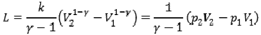
- Once the initial volume is set, the final volume is calculated as V 2 = V 1 - ΔV The final pressure p2 is imposed as equal to the maximum value bearable by the accumulator (about 250 bars), while the initial pressure is calculated as:

- If L > E then the system is able to dissipate all the kinetic energy. The volume V1 must be set to the lowest possible value to reduce the necessary volume of gas and therefore the number of accumulators, always maintaining a certain margin of safety able to ensure the dissipation of all the energy even in off-design conditions.
- Having identified the necessary maximum parameters, the data needed for the sizing and the choice of the number of accumulators can then be identified.
- As the transformation is non-linear, the compression of the gas must start at a precise value of pressure defined by p1 according to which the preload of the accumulator is chosen. In catalogs it is recommended to use a pre-load pressure for the accumulators equal to 90% of the minimum for reasons of wear, therefore

- In reality, in this case, the wear does not represent a big problem because the air pockets are compressed occasionally and not cyclically. Furthermore, as said, to dissipate the energy provided, it is necessary that the oil starts to compress the pocket at the set pressure and not before, because a work performed at a lower pressure for the same volume dissipates less energy and there would be a risk of arriving at the stroke-end without having braked the vehicle and therefore with a speed not equal to zero. For this reason, the preload value of the accumulators is maintained equal to that of the initial compression:

- The nominal volume V 0,TOT needed in total can be calculated as for catalog of the accumulators:

- At this point, it is easy to calculate the minimum number of accumulators required n acc as:

- Where Vacc is the volume of the single accumulator.
- Once these system parameters have been defined, the maximum pressure that is actually achieved and the effective stroke of the arm before the machine stops can then be calculated, and then the safety margin can be evaluated.
- Load losses are also present in the system, which function as damping of the system. Therefore, the slowing down of the arm will be partly helped by the dissipations within the hydraulic components.
- The shock absorption system described above, as well as being deactivated by the
safety device 63 according to the extension of thetelescopic arm 18, can also be deactivated by a command from the operator or automatically by an angle sensor that detects the inclination of thetelescopic arm 18. - Of course, without prejudice to the principle of the invention, the details of construction and the embodiments can be widely varied with respect to those described and illustrated, without thereby departing from the scope of the invention as defined by the claims that follow.
Claims (5)
- A lifting vehicle comprising:- a self-propelled chassis (12),- a telescopic arm (18) provided at a distal end with a implement-mounting attachment (22), and including a base section (30) articulated to the chassis (12) and at least one telescopic section (32),- at least one lifting cylinder (28) arranged between the telescopic arm (18) and the chassis (12),- at least one extension cylinder (34) arranged to control the movement of said at least one telescopic section (32) between a retracted position and a plurality of extracted positions,- a hydraulic circuit (36) including a hydraulic distributor (40) connected to said extension cylinder (34) via a first and a second hydraulic line (42, 44) connected, respectively, to a first and to a second chamber (46, 48) of the extension cylinder (34), wherein a pressure-controlled block valve (52) is arranged on said first hydraulic line (42), characterized in that the hydraulic circuit (36) comprises a shock absorber system (54) including at least one gas accumulator (56) connected to a portion of said first hydraulic line (42) comprised between said first chamber (46) of the extension cylinder (34) and said block valve (52).
- A lifting vehicle according to claim 1, characterized in that said shock absorber system (54) comprises a plurality of accumulators (56) connected in parallel to a common manifold (58).
- A lifting vehicle according to claim 2, characterized in that said accumulators have respective calibration pressures that are different from each other.
- A lifting vehicle according to any one of the preceding claims, characterized in that said shock absorber system (54) comprises an ON/OFF valve (64) that blocks the connection between said at least one accumulator (56) and said first hydraulic line (42) when the extension of said cylinder (34) is higher than a predetermined threshold, or when the angle of the telescopic arm (18) is greater than a predetermined value, or when the shock absorber system (54) is deactivated by the operator.
- A lifting vehicle according to any one of claims 1-4, characterized in that said shock absorber system (54) comprises a pressure-limiting valve, which laminates the hydraulic fluid towards a discharge when the pressure in the accumulator exceeds a predetermined limit value.
Priority Applications (1)
| Application Number | Priority Date | Filing Date | Title |
|---|---|---|---|
| PL16192068T PL3153456T3 (en) | 2015-10-09 | 2016-10-03 | A lifting vehicle with a telescopic lifting arm provided with a shock absorber system |
Applications Claiming Priority (1)
| Application Number | Priority Date | Filing Date | Title |
|---|---|---|---|
| ITUB2015A004253A ITUB20154253A1 (en) | 2015-10-09 | 2015-10-09 | LIFTING VEHICLE WITH A TELESCOPIC LIFTING ARM WITH A SHOCK ABSORBER SYSTEM |
Publications (2)
| Publication Number | Publication Date |
|---|---|
| EP3153456A1 true EP3153456A1 (en) | 2017-04-12 |
| EP3153456B1 EP3153456B1 (en) | 2019-06-19 |
Family
ID=55273345
Family Applications (1)
| Application Number | Title | Priority Date | Filing Date |
|---|---|---|---|
| EP16192068.1A Active EP3153456B1 (en) | 2015-10-09 | 2016-10-03 | A lifting vehicle with a telescopic lifting arm provided with a shock absorber system |
Country Status (4)
| Country | Link |
|---|---|
| EP (1) | EP3153456B1 (en) |
| ES (1) | ES2743708T3 (en) |
| IT (1) | ITUB20154253A1 (en) |
| PL (1) | PL3153456T3 (en) |
Cited By (3)
| Publication number | Priority date | Publication date | Assignee | Title |
|---|---|---|---|---|
| EP3401271A1 (en) * | 2017-05-12 | 2018-11-14 | Robert Bosch GmbH | Variable adjustable event of a fault damper for a lifting device and lifting device |
| WO2019210341A1 (en) | 2018-05-04 | 2019-11-07 | Palfinger Ag | Hydraulic system |
| EP3771684A1 (en) * | 2019-07-30 | 2021-02-03 | Linde Material Handling GmbH | Industrial truck with a lifting device |
Citations (4)
| Publication number | Priority date | Publication date | Assignee | Title |
|---|---|---|---|---|
| US3204573A (en) * | 1962-08-27 | 1965-09-07 | Sferma Soc Fr D Entretien Et D | Hydraulic installations with multiple pressures |
| US4280589A (en) * | 1980-01-31 | 1981-07-28 | Merrick John A | Elevating device |
| EP1733996A1 (en) * | 2005-06-15 | 2006-12-20 | OIL CONTROL S.p.A. | A hydraulic apparatus for raising and lowering an arm hinged to a work vehicle |
| WO2013155178A1 (en) * | 2012-04-11 | 2013-10-17 | Clark Equipment Company | Lift arm suspension system for a power machine |
-
2015
- 2015-10-09 IT ITUB2015A004253A patent/ITUB20154253A1/en unknown
-
2016
- 2016-10-03 PL PL16192068T patent/PL3153456T3/en unknown
- 2016-10-03 ES ES16192068T patent/ES2743708T3/en active Active
- 2016-10-03 EP EP16192068.1A patent/EP3153456B1/en active Active
Patent Citations (4)
| Publication number | Priority date | Publication date | Assignee | Title |
|---|---|---|---|---|
| US3204573A (en) * | 1962-08-27 | 1965-09-07 | Sferma Soc Fr D Entretien Et D | Hydraulic installations with multiple pressures |
| US4280589A (en) * | 1980-01-31 | 1981-07-28 | Merrick John A | Elevating device |
| EP1733996A1 (en) * | 2005-06-15 | 2006-12-20 | OIL CONTROL S.p.A. | A hydraulic apparatus for raising and lowering an arm hinged to a work vehicle |
| WO2013155178A1 (en) * | 2012-04-11 | 2013-10-17 | Clark Equipment Company | Lift arm suspension system for a power machine |
Cited By (5)
| Publication number | Priority date | Publication date | Assignee | Title |
|---|---|---|---|---|
| EP3401271A1 (en) * | 2017-05-12 | 2018-11-14 | Robert Bosch GmbH | Variable adjustable event of a fault damper for a lifting device and lifting device |
| CN108862140A (en) * | 2017-05-12 | 2018-11-23 | 罗伯特·博世有限公司 | Variable adjustable fault dampers and lifts for lifts |
| CN108862140B (en) * | 2017-05-12 | 2022-02-18 | 罗伯特·博世有限公司 | Variably adjustable fault buffer for a lifting mechanism and lifting mechanism |
| WO2019210341A1 (en) | 2018-05-04 | 2019-11-07 | Palfinger Ag | Hydraulic system |
| EP3771684A1 (en) * | 2019-07-30 | 2021-02-03 | Linde Material Handling GmbH | Industrial truck with a lifting device |
Also Published As
| Publication number | Publication date |
|---|---|
| EP3153456B1 (en) | 2019-06-19 |
| ES2743708T3 (en) | 2020-02-20 |
| ITUB20154253A1 (en) | 2017-04-09 |
| PL3153456T3 (en) | 2019-11-29 |
Similar Documents
| Publication | Publication Date | Title |
|---|---|---|
| EP1897847B1 (en) | Charging device | |
| EP2466018B1 (en) | Closed loop drive circuit with external brake assist | |
| EP2652213B1 (en) | Method for energy regeneration in a hydraulic system of a wheel loader | |
| EP3153456B1 (en) | A lifting vehicle with a telescopic lifting arm provided with a shock absorber system | |
| US9086061B2 (en) | Energy recovery hydraulic system | |
| US8186497B2 (en) | Unloading conveyor suspension system | |
| CN102233909B (en) | Vehicle with tilt cab | |
| EP2520536B1 (en) | Lifting vehicle | |
| US20100104409A1 (en) | System and method for a forwarder headboard | |
| US8191928B2 (en) | Stabilizing assembly for a forwarder headboard and method | |
| US9272888B2 (en) | Machine and method of manufacturing a machine | |
| AU2020200132B2 (en) | Support arm, load bunk and vehicle with a support arm | |
| US6334518B1 (en) | Device to absorb impact energy | |
| EP1760327A2 (en) | Hydraulic control | |
| US20130025271A1 (en) | Method and arrangement for active make-up in an overrunning actuator | |
| US8777543B2 (en) | Rollback carrier gravity tilt dampening system | |
| KR102059841B1 (en) | Auto leveling apparatus for tractor | |
| CN104003311B (en) | Fender guard and hoisting crane | |
| CN201677844U (en) | Telescopic vehicle bumper | |
| RU2848854C1 (en) | Recovery pneumohydraulic coupling device for motor train | |
| US3993352A (en) | Energy absorbing dump truck body | |
| JP7722740B2 (en) | Work equipment | |
| GB2084944A (en) | Retractable bumpers for vehicles | |
| DE102010022755A1 (en) | Industrial lorry i.e. counterbalance forklift lorry, has vehicle body provided with electrical actuator, where vehicle body is latched against lateral bending when thrust carriage is moved from alternate position into operational position | |
| CN111994850A (en) | Hydraulic cylinder body with protective structure for hydraulic cylinder |
Legal Events
| Date | Code | Title | Description |
|---|---|---|---|
| PUAI | Public reference made under article 153(3) epc to a published international application that has entered the european phase |
Free format text: ORIGINAL CODE: 0009012 |
|
| STAA | Information on the status of an ep patent application or granted ep patent |
Free format text: STATUS: THE APPLICATION HAS BEEN PUBLISHED |
|
| AK | Designated contracting states |
Kind code of ref document: A1 Designated state(s): AL AT BE BG CH CY CZ DE DK EE ES FI FR GB GR HR HU IE IS IT LI LT LU LV MC MK MT NL NO PL PT RO RS SE SI SK SM TR |
|
| AX | Request for extension of the european patent |
Extension state: BA ME |
|
| STAA | Information on the status of an ep patent application or granted ep patent |
Free format text: STATUS: REQUEST FOR EXAMINATION WAS MADE |
|
| 17P | Request for examination filed |
Effective date: 20170821 |
|
| RBV | Designated contracting states (corrected) |
Designated state(s): AL AT BE BG CH CY CZ DE DK EE ES FI FR GB GR HR HU IE IS IT LI LT LU LV MC MK MT NL NO PL PT RO RS SE SI SK SM TR |
|
| RIC1 | Information provided on ipc code assigned before grant |
Ipc: F15B 20/00 20060101ALI20181130BHEP Ipc: F15B 1/02 20060101ALI20181130BHEP Ipc: B66F 9/22 20060101ALI20181130BHEP Ipc: B66F 11/04 20060101ALI20181130BHEP Ipc: B66F 9/065 20060101AFI20181130BHEP Ipc: E02F 9/22 20060101ALI20181130BHEP |
|
| GRAP | Despatch of communication of intention to grant a patent |
Free format text: ORIGINAL CODE: EPIDOSNIGR1 |
|
| STAA | Information on the status of an ep patent application or granted ep patent |
Free format text: STATUS: GRANT OF PATENT IS INTENDED |
|
| INTG | Intention to grant announced |
Effective date: 20190124 |
|
| GRAS | Grant fee paid |
Free format text: ORIGINAL CODE: EPIDOSNIGR3 |
|
| GRAA | (expected) grant |
Free format text: ORIGINAL CODE: 0009210 |
|
| STAA | Information on the status of an ep patent application or granted ep patent |
Free format text: STATUS: THE PATENT HAS BEEN GRANTED |
|
| AK | Designated contracting states |
Kind code of ref document: B1 Designated state(s): AL AT BE BG CH CY CZ DE DK EE ES FI FR GB GR HR HU IE IS IT LI LT LU LV MC MK MT NL NO PL PT RO RS SE SI SK SM TR |
|
| REG | Reference to a national code |
Ref country code: GB Ref legal event code: FG4D |
|
| REG | Reference to a national code |
Ref country code: CH Ref legal event code: EP Ref country code: CH Ref legal event code: NV Representative=s name: ISLER AND PEDRAZZINI AG, CH |
|
| REG | Reference to a national code |
Ref country code: IE Ref legal event code: FG4D |
|
| REG | Reference to a national code |
Ref country code: DE Ref legal event code: R096 Ref document number: 602016015458 Country of ref document: DE |
|
| REG | Reference to a national code |
Ref country code: AT Ref legal event code: REF Ref document number: 1145250 Country of ref document: AT Kind code of ref document: T Effective date: 20190715 |
|
| REG | Reference to a national code |
Ref country code: NL Ref legal event code: FP |
|
| PG25 | Lapsed in a contracting state [announced via postgrant information from national office to epo] |
Ref country code: HR Free format text: LAPSE BECAUSE OF FAILURE TO SUBMIT A TRANSLATION OF THE DESCRIPTION OR TO PAY THE FEE WITHIN THE PRESCRIBED TIME-LIMIT Effective date: 20190619 Ref country code: LT Free format text: LAPSE BECAUSE OF FAILURE TO SUBMIT A TRANSLATION OF THE DESCRIPTION OR TO PAY THE FEE WITHIN THE PRESCRIBED TIME-LIMIT Effective date: 20190619 Ref country code: SE Free format text: LAPSE BECAUSE OF FAILURE TO SUBMIT A TRANSLATION OF THE DESCRIPTION OR TO PAY THE FEE WITHIN THE PRESCRIBED TIME-LIMIT Effective date: 20190619 Ref country code: FI Free format text: LAPSE BECAUSE OF FAILURE TO SUBMIT A TRANSLATION OF THE DESCRIPTION OR TO PAY THE FEE WITHIN THE PRESCRIBED TIME-LIMIT Effective date: 20190619 Ref country code: AL Free format text: LAPSE BECAUSE OF FAILURE TO SUBMIT A TRANSLATION OF THE DESCRIPTION OR TO PAY THE FEE WITHIN THE PRESCRIBED TIME-LIMIT Effective date: 20190619 Ref country code: NO Free format text: LAPSE BECAUSE OF FAILURE TO SUBMIT A TRANSLATION OF THE DESCRIPTION OR TO PAY THE FEE WITHIN THE PRESCRIBED TIME-LIMIT Effective date: 20190919 |
|
| REG | Reference to a national code |
Ref country code: LT Ref legal event code: MG4D |
|
| PG25 | Lapsed in a contracting state [announced via postgrant information from national office to epo] |
Ref country code: BG Free format text: LAPSE BECAUSE OF FAILURE TO SUBMIT A TRANSLATION OF THE DESCRIPTION OR TO PAY THE FEE WITHIN THE PRESCRIBED TIME-LIMIT Effective date: 20190919 Ref country code: GR Free format text: LAPSE BECAUSE OF FAILURE TO SUBMIT A TRANSLATION OF THE DESCRIPTION OR TO PAY THE FEE WITHIN THE PRESCRIBED TIME-LIMIT Effective date: 20190920 Ref country code: RS Free format text: LAPSE BECAUSE OF FAILURE TO SUBMIT A TRANSLATION OF THE DESCRIPTION OR TO PAY THE FEE WITHIN THE PRESCRIBED TIME-LIMIT Effective date: 20190619 Ref country code: LV Free format text: LAPSE BECAUSE OF FAILURE TO SUBMIT A TRANSLATION OF THE DESCRIPTION OR TO PAY THE FEE WITHIN THE PRESCRIBED TIME-LIMIT Effective date: 20190619 |
|
| PG25 | Lapsed in a contracting state [announced via postgrant information from national office to epo] |
Ref country code: EE Free format text: LAPSE BECAUSE OF FAILURE TO SUBMIT A TRANSLATION OF THE DESCRIPTION OR TO PAY THE FEE WITHIN THE PRESCRIBED TIME-LIMIT Effective date: 20190619 Ref country code: PT Free format text: LAPSE BECAUSE OF FAILURE TO SUBMIT A TRANSLATION OF THE DESCRIPTION OR TO PAY THE FEE WITHIN THE PRESCRIBED TIME-LIMIT Effective date: 20191021 Ref country code: RO Free format text: LAPSE BECAUSE OF FAILURE TO SUBMIT A TRANSLATION OF THE DESCRIPTION OR TO PAY THE FEE WITHIN THE PRESCRIBED TIME-LIMIT Effective date: 20190619 Ref country code: CZ Free format text: LAPSE BECAUSE OF FAILURE TO SUBMIT A TRANSLATION OF THE DESCRIPTION OR TO PAY THE FEE WITHIN THE PRESCRIBED TIME-LIMIT Effective date: 20190619 Ref country code: SK Free format text: LAPSE BECAUSE OF FAILURE TO SUBMIT A TRANSLATION OF THE DESCRIPTION OR TO PAY THE FEE WITHIN THE PRESCRIBED TIME-LIMIT Effective date: 20190619 |
|
| PG25 | Lapsed in a contracting state [announced via postgrant information from national office to epo] |
Ref country code: IS Free format text: LAPSE BECAUSE OF FAILURE TO SUBMIT A TRANSLATION OF THE DESCRIPTION OR TO PAY THE FEE WITHIN THE PRESCRIBED TIME-LIMIT Effective date: 20191019 Ref country code: SM Free format text: LAPSE BECAUSE OF FAILURE TO SUBMIT A TRANSLATION OF THE DESCRIPTION OR TO PAY THE FEE WITHIN THE PRESCRIBED TIME-LIMIT Effective date: 20190619 |
|
| PG25 | Lapsed in a contracting state [announced via postgrant information from national office to epo] |
Ref country code: TR Free format text: LAPSE BECAUSE OF FAILURE TO SUBMIT A TRANSLATION OF THE DESCRIPTION OR TO PAY THE FEE WITHIN THE PRESCRIBED TIME-LIMIT Effective date: 20190619 |
|
| PG25 | Lapsed in a contracting state [announced via postgrant information from national office to epo] |
Ref country code: DK Free format text: LAPSE BECAUSE OF FAILURE TO SUBMIT A TRANSLATION OF THE DESCRIPTION OR TO PAY THE FEE WITHIN THE PRESCRIBED TIME-LIMIT Effective date: 20190619 |
|
| REG | Reference to a national code |
Ref country code: AT Ref legal event code: UEP Ref document number: 1145250 Country of ref document: AT Kind code of ref document: T Effective date: 20190619 |
|
| PG25 | Lapsed in a contracting state [announced via postgrant information from national office to epo] |
Ref country code: MC Free format text: LAPSE BECAUSE OF FAILURE TO SUBMIT A TRANSLATION OF THE DESCRIPTION OR TO PAY THE FEE WITHIN THE PRESCRIBED TIME-LIMIT Effective date: 20190619 Ref country code: IS Free format text: LAPSE BECAUSE OF FAILURE TO SUBMIT A TRANSLATION OF THE DESCRIPTION OR TO PAY THE FEE WITHIN THE PRESCRIBED TIME-LIMIT Effective date: 20200224 |
|
| REG | Reference to a national code |
Ref country code: DE Ref legal event code: R097 Ref document number: 602016015458 Country of ref document: DE |
|
| PLBE | No opposition filed within time limit |
Free format text: ORIGINAL CODE: 0009261 |
|
| STAA | Information on the status of an ep patent application or granted ep patent |
Free format text: STATUS: NO OPPOSITION FILED WITHIN TIME LIMIT |
|
| PG2D | Information on lapse in contracting state deleted |
Ref country code: IS |
|
| PG25 | Lapsed in a contracting state [announced via postgrant information from national office to epo] |
Ref country code: LU Free format text: LAPSE BECAUSE OF NON-PAYMENT OF DUE FEES Effective date: 20191003 |
|
| 26N | No opposition filed |
Effective date: 20200603 |
|
| PG25 | Lapsed in a contracting state [announced via postgrant information from national office to epo] |
Ref country code: SI Free format text: LAPSE BECAUSE OF FAILURE TO SUBMIT A TRANSLATION OF THE DESCRIPTION OR TO PAY THE FEE WITHIN THE PRESCRIBED TIME-LIMIT Effective date: 20190619 |
|
| PG25 | Lapsed in a contracting state [announced via postgrant information from national office to epo] |
Ref country code: IE Free format text: LAPSE BECAUSE OF NON-PAYMENT OF DUE FEES Effective date: 20191003 |
|
| PG25 | Lapsed in a contracting state [announced via postgrant information from national office to epo] |
Ref country code: CY Free format text: LAPSE BECAUSE OF FAILURE TO SUBMIT A TRANSLATION OF THE DESCRIPTION OR TO PAY THE FEE WITHIN THE PRESCRIBED TIME-LIMIT Effective date: 20190619 |
|
| PG25 | Lapsed in a contracting state [announced via postgrant information from national office to epo] |
Ref country code: MT Free format text: LAPSE BECAUSE OF FAILURE TO SUBMIT A TRANSLATION OF THE DESCRIPTION OR TO PAY THE FEE WITHIN THE PRESCRIBED TIME-LIMIT Effective date: 20190619 Ref country code: HU Free format text: LAPSE BECAUSE OF FAILURE TO SUBMIT A TRANSLATION OF THE DESCRIPTION OR TO PAY THE FEE WITHIN THE PRESCRIBED TIME-LIMIT; INVALID AB INITIO Effective date: 20161003 |
|
| PG25 | Lapsed in a contracting state [announced via postgrant information from national office to epo] |
Ref country code: MK Free format text: LAPSE BECAUSE OF FAILURE TO SUBMIT A TRANSLATION OF THE DESCRIPTION OR TO PAY THE FEE WITHIN THE PRESCRIBED TIME-LIMIT Effective date: 20190619 |
|
| P01 | Opt-out of the competence of the unified patent court (upc) registered |
Effective date: 20230529 |
|
| PGFP | Annual fee paid to national office [announced via postgrant information from national office to epo] |
Ref country code: PL Payment date: 20250910 Year of fee payment: 10 |
|
| REG | Reference to a national code |
Ref country code: CH Ref legal event code: U11 Free format text: ST27 STATUS EVENT CODE: U-0-0-U10-U11 (AS PROVIDED BY THE NATIONAL OFFICE) Effective date: 20251101 |
|
| PGFP | Annual fee paid to national office [announced via postgrant information from national office to epo] |
Ref country code: NL Payment date: 20251024 Year of fee payment: 10 |
|
| PGFP | Annual fee paid to national office [announced via postgrant information from national office to epo] |
Ref country code: DE Payment date: 20251028 Year of fee payment: 10 |
|
| PGFP | Annual fee paid to national office [announced via postgrant information from national office to epo] |
Ref country code: GB Payment date: 20251023 Year of fee payment: 10 |
|
| PGFP | Annual fee paid to national office [announced via postgrant information from national office to epo] |
Ref country code: AT Payment date: 20250917 Year of fee payment: 10 |
|
| PGFP | Annual fee paid to national office [announced via postgrant information from national office to epo] |
Ref country code: IT Payment date: 20251006 Year of fee payment: 10 |
|
| PGFP | Annual fee paid to national office [announced via postgrant information from national office to epo] |
Ref country code: FR Payment date: 20251027 Year of fee payment: 10 |
|
| PGFP | Annual fee paid to national office [announced via postgrant information from national office to epo] |
Ref country code: BE Payment date: 20251024 Year of fee payment: 10 |
|
| PGFP | Annual fee paid to national office [announced via postgrant information from national office to epo] |
Ref country code: CH Payment date: 20251101 Year of fee payment: 10 |
|
| PGFP | Annual fee paid to national office [announced via postgrant information from national office to epo] |
Ref country code: ES Payment date: 20251118 Year of fee payment: 10 |