EP3153410A1 - Methods for diverting lightning current from skin fasteners in composite, non-metallic structures - Google Patents
Methods for diverting lightning current from skin fasteners in composite, non-metallic structures Download PDFInfo
- Publication number
- EP3153410A1 EP3153410A1 EP16189302.9A EP16189302A EP3153410A1 EP 3153410 A1 EP3153410 A1 EP 3153410A1 EP 16189302 A EP16189302 A EP 16189302A EP 3153410 A1 EP3153410 A1 EP 3153410A1
- Authority
- EP
- European Patent Office
- Prior art keywords
- conductive layer
- layer
- holes
- composite structure
- conductive
- Prior art date
- Legal status (The legal status is an assumption and is not a legal conclusion. Google has not performed a legal analysis and makes no representation as to the accuracy of the status listed.)
- Granted
Links
Images




Classifications
-
- B—PERFORMING OPERATIONS; TRANSPORTING
- B29—WORKING OF PLASTICS; WORKING OF SUBSTANCES IN A PLASTIC STATE IN GENERAL
- B29C—SHAPING OR JOINING OF PLASTICS; SHAPING OF MATERIAL IN A PLASTIC STATE, NOT OTHERWISE PROVIDED FOR; AFTER-TREATMENT OF THE SHAPED PRODUCTS, e.g. REPAIRING
- B29C70/00—Shaping composites, i.e. plastics material comprising reinforcements, fillers or preformed parts, e.g. inserts
- B29C70/04—Shaping composites, i.e. plastics material comprising reinforcements, fillers or preformed parts, e.g. inserts comprising reinforcements only, e.g. self-reinforcing plastics
- B29C70/28—Shaping operations therefor
- B29C70/54—Component parts, details or accessories; Auxiliary operations, e.g. feeding or storage of prepregs or SMC after impregnation or during ageing
- B29C70/545—Perforating, cutting or machining during or after moulding
-
- B—PERFORMING OPERATIONS; TRANSPORTING
- B29—WORKING OF PLASTICS; WORKING OF SUBSTANCES IN A PLASTIC STATE IN GENERAL
- B29C—SHAPING OR JOINING OF PLASTICS; SHAPING OF MATERIAL IN A PLASTIC STATE, NOT OTHERWISE PROVIDED FOR; AFTER-TREATMENT OF THE SHAPED PRODUCTS, e.g. REPAIRING
- B29C70/00—Shaping composites, i.e. plastics material comprising reinforcements, fillers or preformed parts, e.g. inserts
- B29C70/88—Shaping composites, i.e. plastics material comprising reinforcements, fillers or preformed parts, e.g. inserts characterised primarily by possessing specific properties, e.g. electrically conductive or locally reinforced
-
- B—PERFORMING OPERATIONS; TRANSPORTING
- B29—WORKING OF PLASTICS; WORKING OF SUBSTANCES IN A PLASTIC STATE IN GENERAL
- B29C—SHAPING OR JOINING OF PLASTICS; SHAPING OF MATERIAL IN A PLASTIC STATE, NOT OTHERWISE PROVIDED FOR; AFTER-TREATMENT OF THE SHAPED PRODUCTS, e.g. REPAIRING
- B29C70/00—Shaping composites, i.e. plastics material comprising reinforcements, fillers or preformed parts, e.g. inserts
- B29C70/88—Shaping composites, i.e. plastics material comprising reinforcements, fillers or preformed parts, e.g. inserts characterised primarily by possessing specific properties, e.g. electrically conductive or locally reinforced
- B29C70/882—Shaping composites, i.e. plastics material comprising reinforcements, fillers or preformed parts, e.g. inserts characterised primarily by possessing specific properties, e.g. electrically conductive or locally reinforced partly or totally electrically conductive, e.g. for EMI shielding
-
- B—PERFORMING OPERATIONS; TRANSPORTING
- B29—WORKING OF PLASTICS; WORKING OF SUBSTANCES IN A PLASTIC STATE IN GENERAL
- B29C—SHAPING OR JOINING OF PLASTICS; SHAPING OF MATERIAL IN A PLASTIC STATE, NOT OTHERWISE PROVIDED FOR; AFTER-TREATMENT OF THE SHAPED PRODUCTS, e.g. REPAIRING
- B29C70/00—Shaping composites, i.e. plastics material comprising reinforcements, fillers or preformed parts, e.g. inserts
- B29C70/88—Shaping composites, i.e. plastics material comprising reinforcements, fillers or preformed parts, e.g. inserts characterised primarily by possessing specific properties, e.g. electrically conductive or locally reinforced
- B29C70/882—Shaping composites, i.e. plastics material comprising reinforcements, fillers or preformed parts, e.g. inserts characterised primarily by possessing specific properties, e.g. electrically conductive or locally reinforced partly or totally electrically conductive, e.g. for EMI shielding
- B29C70/885—Shaping composites, i.e. plastics material comprising reinforcements, fillers or preformed parts, e.g. inserts characterised primarily by possessing specific properties, e.g. electrically conductive or locally reinforced partly or totally electrically conductive, e.g. for EMI shielding with incorporated metallic wires, nets, films or plates
-
- B—PERFORMING OPERATIONS; TRANSPORTING
- B32—LAYERED PRODUCTS
- B32B—LAYERED PRODUCTS, i.e. PRODUCTS BUILT-UP OF STRATA OF FLAT OR NON-FLAT, e.g. CELLULAR OR HONEYCOMB, FORM
- B32B15/00—Layered products comprising a layer of metal
- B32B15/02—Layer formed of wires, e.g. mesh
-
- B—PERFORMING OPERATIONS; TRANSPORTING
- B32—LAYERED PRODUCTS
- B32B—LAYERED PRODUCTS, i.e. PRODUCTS BUILT-UP OF STRATA OF FLAT OR NON-FLAT, e.g. CELLULAR OR HONEYCOMB, FORM
- B32B15/00—Layered products comprising a layer of metal
- B32B15/04—Layered products comprising a layer of metal comprising metal as the main or only constituent of a layer, which is next to another layer of the same or of a different material
- B32B15/08—Layered products comprising a layer of metal comprising metal as the main or only constituent of a layer, which is next to another layer of the same or of a different material of synthetic resin
-
- B—PERFORMING OPERATIONS; TRANSPORTING
- B32—LAYERED PRODUCTS
- B32B—LAYERED PRODUCTS, i.e. PRODUCTS BUILT-UP OF STRATA OF FLAT OR NON-FLAT, e.g. CELLULAR OR HONEYCOMB, FORM
- B32B27/00—Layered products comprising a layer of synthetic resin
- B32B27/06—Layered products comprising a layer of synthetic resin as the main or only constituent of a layer, which is next to another layer of the same or of a different material
-
- B—PERFORMING OPERATIONS; TRANSPORTING
- B32—LAYERED PRODUCTS
- B32B—LAYERED PRODUCTS, i.e. PRODUCTS BUILT-UP OF STRATA OF FLAT OR NON-FLAT, e.g. CELLULAR OR HONEYCOMB, FORM
- B32B3/00—Layered products comprising a layer with external or internal discontinuities or unevennesses, or a layer of non-planar shape; Layered products comprising a layer having particular features of form
- B32B3/02—Layered products comprising a layer with external or internal discontinuities or unevennesses, or a layer of non-planar shape; Layered products comprising a layer having particular features of form characterised by features of form at particular places, e.g. in edge regions
- B32B3/08—Layered products comprising a layer with external or internal discontinuities or unevennesses, or a layer of non-planar shape; Layered products comprising a layer having particular features of form characterised by features of form at particular places, e.g. in edge regions characterised by added members at particular parts
- B32B3/085—Layered products comprising a layer with external or internal discontinuities or unevennesses, or a layer of non-planar shape; Layered products comprising a layer having particular features of form characterised by features of form at particular places, e.g. in edge regions characterised by added members at particular parts spaced apart pieces on the surface of a layer
-
- B—PERFORMING OPERATIONS; TRANSPORTING
- B32—LAYERED PRODUCTS
- B32B—LAYERED PRODUCTS, i.e. PRODUCTS BUILT-UP OF STRATA OF FLAT OR NON-FLAT, e.g. CELLULAR OR HONEYCOMB, FORM
- B32B3/00—Layered products comprising a layer with external or internal discontinuities or unevennesses, or a layer of non-planar shape; Layered products comprising a layer having particular features of form
- B32B3/10—Layered products comprising a layer with external or internal discontinuities or unevennesses, or a layer of non-planar shape; Layered products comprising a layer having particular features of form characterised by a discontinuous layer, i.e. formed of separate pieces of material
- B32B3/12—Layered products comprising a layer with external or internal discontinuities or unevennesses, or a layer of non-planar shape; Layered products comprising a layer having particular features of form characterised by a discontinuous layer, i.e. formed of separate pieces of material characterised by a layer of regularly- arranged cells, e.g. a honeycomb structure
-
- B—PERFORMING OPERATIONS; TRANSPORTING
- B32—LAYERED PRODUCTS
- B32B—LAYERED PRODUCTS, i.e. PRODUCTS BUILT-UP OF STRATA OF FLAT OR NON-FLAT, e.g. CELLULAR OR HONEYCOMB, FORM
- B32B33/00—Layered products characterised by particular properties or particular surface features, e.g. particular surface coatings; Layered products designed for particular purposes not covered by another single class
-
- B—PERFORMING OPERATIONS; TRANSPORTING
- B32—LAYERED PRODUCTS
- B32B—LAYERED PRODUCTS, i.e. PRODUCTS BUILT-UP OF STRATA OF FLAT OR NON-FLAT, e.g. CELLULAR OR HONEYCOMB, FORM
- B32B37/00—Methods or apparatus for laminating, e.g. by curing or by ultrasonic bonding
- B32B37/02—Methods or apparatus for laminating, e.g. by curing or by ultrasonic bonding characterised by a sequence of laminating steps, e.g. by adding new layers at consecutive laminating stations
-
- B—PERFORMING OPERATIONS; TRANSPORTING
- B32—LAYERED PRODUCTS
- B32B—LAYERED PRODUCTS, i.e. PRODUCTS BUILT-UP OF STRATA OF FLAT OR NON-FLAT, e.g. CELLULAR OR HONEYCOMB, FORM
- B32B37/00—Methods or apparatus for laminating, e.g. by curing or by ultrasonic bonding
- B32B37/12—Methods or apparatus for laminating, e.g. by curing or by ultrasonic bonding characterised by using adhesives
-
- B—PERFORMING OPERATIONS; TRANSPORTING
- B32—LAYERED PRODUCTS
- B32B—LAYERED PRODUCTS, i.e. PRODUCTS BUILT-UP OF STRATA OF FLAT OR NON-FLAT, e.g. CELLULAR OR HONEYCOMB, FORM
- B32B7/00—Layered products characterised by the relation between layers; Layered products characterised by the relative orientation of features between layers, or by the relative values of a measurable parameter between layers, i.e. products comprising layers having different physical, chemical or physicochemical properties; Layered products characterised by the interconnection of layers
- B32B7/04—Interconnection of layers
- B32B7/12—Interconnection of layers using interposed adhesives or interposed materials with bonding properties
-
- B—PERFORMING OPERATIONS; TRANSPORTING
- B64—AIRCRAFT; AVIATION; COSMONAUTICS
- B64C—AEROPLANES; HELICOPTERS
- B64C1/00—Fuselages; Constructional features common to fuselages, wings, stabilising surfaces or the like
- B64C1/06—Frames; Stringers; Longerons ; Fuselage sections
- B64C1/12—Construction or attachment of skin panels
-
- B—PERFORMING OPERATIONS; TRANSPORTING
- B64—AIRCRAFT; AVIATION; COSMONAUTICS
- B64D—EQUIPMENT FOR FITTING IN OR TO AIRCRAFT; FLIGHT SUITS; PARACHUTES; ARRANGEMENT OR MOUNTING OF POWER PLANTS OR PROPULSION TRANSMISSIONS IN AIRCRAFT
- B64D37/00—Arrangements in connection with fuel supply for power plant
- B64D37/32—Safety measures not otherwise provided for, e.g. preventing explosive conditions
-
- B—PERFORMING OPERATIONS; TRANSPORTING
- B64—AIRCRAFT; AVIATION; COSMONAUTICS
- B64D—EQUIPMENT FOR FITTING IN OR TO AIRCRAFT; FLIGHT SUITS; PARACHUTES; ARRANGEMENT OR MOUNTING OF POWER PLANTS OR PROPULSION TRANSMISSIONS IN AIRCRAFT
- B64D45/00—Aircraft indicators or protectors not otherwise provided for
- B64D45/02—Lightning protectors; Static dischargers
-
- F—MECHANICAL ENGINEERING; LIGHTING; HEATING; WEAPONS; BLASTING
- F16—ENGINEERING ELEMENTS AND UNITS; GENERAL MEASURES FOR PRODUCING AND MAINTAINING EFFECTIVE FUNCTIONING OF MACHINES OR INSTALLATIONS; THERMAL INSULATION IN GENERAL
- F16B—DEVICES FOR FASTENING OR SECURING CONSTRUCTIONAL ELEMENTS OR MACHINE PARTS TOGETHER, e.g. NAILS, BOLTS, CIRCLIPS, CLAMPS, CLIPS OR WEDGES; JOINTS OR JOINTING
- F16B37/00—Nuts or like thread-engaging members
- F16B37/14—Cap nuts; Nut caps or bolt caps
-
- H—ELECTRICITY
- H02—GENERATION; CONVERSION OR DISTRIBUTION OF ELECTRIC POWER
- H02G—INSTALLATION OF ELECTRIC CABLES OR LINES, OR OF COMBINED OPTICAL AND ELECTRIC CABLES OR LINES
- H02G13/00—Installations of lightning conductors; Fastening thereof to supporting structure
-
- H—ELECTRICITY
- H02—GENERATION; CONVERSION OR DISTRIBUTION OF ELECTRIC POWER
- H02G—INSTALLATION OF ELECTRIC CABLES OR LINES, OR OF COMBINED OPTICAL AND ELECTRIC CABLES OR LINES
- H02G13/00—Installations of lightning conductors; Fastening thereof to supporting structure
- H02G13/80—Discharge by conduction or dissipation, e.g. rods, arresters, spark gaps
-
- B—PERFORMING OPERATIONS; TRANSPORTING
- B32—LAYERED PRODUCTS
- B32B—LAYERED PRODUCTS, i.e. PRODUCTS BUILT-UP OF STRATA OF FLAT OR NON-FLAT, e.g. CELLULAR OR HONEYCOMB, FORM
- B32B2260/00—Layered product comprising an impregnated, embedded, or bonded layer wherein the layer comprises an impregnation, embedding, or binder material
- B32B2260/02—Composition of the impregnated, bonded or embedded layer
- B32B2260/021—Fibrous or filamentary layer
-
- B—PERFORMING OPERATIONS; TRANSPORTING
- B32—LAYERED PRODUCTS
- B32B—LAYERED PRODUCTS, i.e. PRODUCTS BUILT-UP OF STRATA OF FLAT OR NON-FLAT, e.g. CELLULAR OR HONEYCOMB, FORM
- B32B2260/00—Layered product comprising an impregnated, embedded, or bonded layer wherein the layer comprises an impregnation, embedding, or binder material
- B32B2260/04—Impregnation, embedding, or binder material
- B32B2260/046—Synthetic resin
-
- B—PERFORMING OPERATIONS; TRANSPORTING
- B32—LAYERED PRODUCTS
- B32B—LAYERED PRODUCTS, i.e. PRODUCTS BUILT-UP OF STRATA OF FLAT OR NON-FLAT, e.g. CELLULAR OR HONEYCOMB, FORM
- B32B2307/00—Properties of the layers or laminate
- B32B2307/20—Properties of the layers or laminate having particular electrical or magnetic properties, e.g. piezoelectric
- B32B2307/202—Conductive
-
- B—PERFORMING OPERATIONS; TRANSPORTING
- B32—LAYERED PRODUCTS
- B32B—LAYERED PRODUCTS, i.e. PRODUCTS BUILT-UP OF STRATA OF FLAT OR NON-FLAT, e.g. CELLULAR OR HONEYCOMB, FORM
- B32B2605/00—Vehicles
- B32B2605/18—Aircraft
-
- Y—GENERAL TAGGING OF NEW TECHNOLOGICAL DEVELOPMENTS; GENERAL TAGGING OF CROSS-SECTIONAL TECHNOLOGIES SPANNING OVER SEVERAL SECTIONS OF THE IPC; TECHNICAL SUBJECTS COVERED BY FORMER USPC CROSS-REFERENCE ART COLLECTIONS [XRACs] AND DIGESTS
- Y02—TECHNOLOGIES OR APPLICATIONS FOR MITIGATION OR ADAPTATION AGAINST CLIMATE CHANGE
- Y02T—CLIMATE CHANGE MITIGATION TECHNOLOGIES RELATED TO TRANSPORTATION
- Y02T50/00—Aeronautics or air transport
- Y02T50/40—Weight reduction
Definitions
- Embodiments of the disclosure relate generally to the field of lightning protection of non-metallic structures and more particularly to lightning protection of aerospace structures fabricated from carbon fiber reinforced plastic (CFRP) composite systems.
- CFRP carbon fiber reinforced plastic
- Lightning protection is a requirement for all aircraft, particularly aircraft with composite structures. Due to its high strength to weight ratio, carbon fiber reinforced plastic (CFRP) material systems are increasingly used for aerospace structures. However, since carbon fiber is 2000 times more resistive than aluminum and is embedded in a matrix that typically consists of 35-40 weight % non- conductive contents, damage from direct lightning strikes to the CFRP structures is more severe and efforts to protect the CFRP structures from lightning direct attachment have required significant attention to ensure continued airworthiness of the design.
- Metallic skin fasteners, particularly fasteners in composite/non-metallic wing skins require special attention as they are more susceptible to direct lightning attachment, if unprotected, and may lead to fuel tank ignition.
- Embodiments disclosed herein provide a multilayer composite structure with integrated fastener- to-conductive layer surface lightning protection interconnections having a co-cured conductive layer, such as a wire mesh, with an inner surface and a plurality of chamfered recesses forming part of countersinks in an outer surface.
- a co-cured conductive layer such as a wire mesh
- One or more carbon-fiber reinforced plastic (CFRP) composite layers are disposed on the inner surface of the co-cured conductive layer and conforms to the surface shape.
- a plurality of holes extend through the plurality of chamfered recesses in the co-cured conductive layer and the adjoining CFRP composite layer in a manner such that the co-cured conductive layer defines a countersink portion extending into the openings of the plurality of holes.
- the chamfered recesses in the co-cured conductive layer increase an electrically conductive surface area that contacts conductive, metallic countersunk fasteners installed within the plurality of holes.
- a feature of one embodiment includes a carbon fiber reinforced plastic (CFRP) composite structure having a hole with a countersink and a conical washer inserted in the countersink.
- a fastener received with a clearance fit in the hole has a conical head conductively engaging the conical washer whereby any lightning current attaching to or conducting through the head of the fastener is dissipated in a discharge path primarily through the composite layers in an outer portion of the composite structure extending adjacent from the fastener head.
- CFRP carbon fiber reinforced plastic
- the embodiments disclosed may be fabricated using a method of forming a multilayer composite structure with integrated fastener- to-conductive layer surface lightning protection interconnections.
- a glass fiber reinforced pre-impregnated layer or surfacing film is laid over a tool having a plurality of raised conical-shaped features.
- a conductive surface protection layer is then laid over the fiber glass or surfacing film layer to form a plurality of chamfered recesses in the co-cured conductive layer.
- Carbon-fiber reinforced plastic (CFRP) composite layers are then laid over the fiber glass or surfacing film layer and the conductive layer. The entire layup is then co-cured on the tool.
- CFRP Carbon-fiber reinforced plastic
- a plurality of holes are machined through the plurality of recesses in the conductive layer and the adjoining composite layer in a manner such that the chamfered recesses expose the conductive layer surface and define the finished countersink dimensions.
- Fasteners are then inserted into the plurality of holes such that the chamfered recesses in the countersinks with the conductive layer provide the electrical connection to the countersunk heads of the metallic fasteners installed within the plurality of holes.
- Embodiments disclosed herein provide lightning and/or other forms of electrical current dissipation in a first embodiment through electrical contact between a conical washer and outer layers of a composite structure and a conical head of a fastener extending through the composite structure.
- a shaft of the fastener is received in the composite structure in a clearance fit hole.
- current dissipation is enhanced through direct electrical connection between a conductive layer co-cured in a composite structure and fasteners in the composite structure.
- the co-cured conductive layer extends inside a portion of the fastener holes and makes contact with heads of the fasteners or a conical washer interfacing the fastener head into the countersink after installation.
- the composite structure is realized by first laying down a fiber glass or surfacing film as a protective outer layer, a conductive layer such as a wire mesh, an adhesive layer (which may be integrated with the conductive layer or applied to the conductive layer prior to layup), followed by the subsequent CFRP tape layers in accordance with the structural design on a uniquely designed laminating tool with raised features. These raised features are designed to provide part of the countersink holes (typical angle of 100 degrees) for the skin fasteners that will be installed later. After curing, the laminated skin is then removed from the laminating tool, then drilled at the location of the raised features and appropriately finished to provide the countersink holes for fastener installation.
- Countersinking of the holes at the location of the raised features removes only the fiber glass or surfacing film outer layer on the angled surfaces of the formed indentations.
- conical washers of a desired metal type having a density and thickness may be added to the countersink hole to form electrical contacts with both the portion in the countersink holes with the conductive layer and the fastener heads.
- FIG. 1 shows an exemplary prior art fastener installation in which a fastener 10 is received with an interference fit (fit spacing is exaggerated in the drawing for clarity of the elements) by a sleeve 12 inserted in a countersunk hole 14 in a multilayer composite structure 16 such as a CFRP skin.
- Fastener head 18 and fastener shaft 20 are both in electrical contact with the sleeve 12 which, in turn is in electrical contact with the composite structure 16.
- Lightning current attaching to or conducting through the head 18 of the fastener is dissipated into the composite structure throughout the length of the fastener head and shaft as indicated by arrows 22.
- the fastener 10 is secured with a nut / collar 24 received on a threaded end 26 to secure the composite structure to another structural member 25.
- This discharge path results in uniform current distribution through layers in the composite structure, such as the example skin layup and higher current density at fastener collar/nut may result in enhanced fuel tank sealing requirements.
- FIG. 2 The first embodiment disclosed is shown in FIG. 2 wherein fastener 30 having a head 32 and shaft 34 is received in a countersunk hole 36 in a CFRP composite structure 38 such as a wing skin. A clearance fit is provided between the shaft 34 and hole 36. An angled countersink 40 in the hole 36 provides a mating surface having an angle concentric with the fastener head 32. A conical washer 42 is engaged between the head 32 and the countersink 40 providing electrical contact between the head and an outer portion 44 of the composite structure 38. This intimate electrical contact dissipates any electrical current conducting through the head 32 of the fastener 30 in a discharge path (represented by arrows 46) primarily through the composite layers in the outer portion 44 of the composite structure extending adjacent from the fastener head.
- a discharge path represented by arrows 46
- the fastener 30 is secured with a nut/collar 48, or a nut with separate washer, received on a threaded end 50 to secure the composite structure 38 to another structural member 49.
- a nut/collar 48 or a nut with separate washer, received on a threaded end 50 to secure the composite structure 38 to another structural member 49.
- the conical washer 42, countersink in the hole 36 and the head 32 have an angle of between 98° and 102°, nominally 100° and the conical washer has a thickness of between 0.001 and 0.005 inches.
- a titanium fastener is employed and the conical washer is bare corrosion resistant steel (CRES) to provide the desired conductivity.
- CRES bare corrosion resistant steel
- FIGs 3A - 3E illustrate a desired structure for an exemplary wing skin integral to a fuel tank in an aircraft.
- a multilayer composite structure 52 with integrated fastener-to-conductive layer surface protection interconnection is formed by employing a laminating tool 54, as seen in FIG. 3A , having a plurality of raised conical-shaped features or protrusions 56 positioned at desired fastener locations.
- a fiberglass or surfacing film layer 58 is placed on the tool to initiate the layup with the fiberglass or surfacing layer conforming to each of the conical shaped features 56.
- a conductive layer such as a wire mesh 60 is laid up over the fiberglass or surfacing film layer 58 with an outer surface 59 adjacent the fiberglass or surfacing film layer.
- the wire mesh layer is an expanded metal foil, such as copper, nickel or aluminum, with thickness ranging from 0.001 to 0.005 inch.
- An adhesive layer 62 is placed or applied over the wire mesh layer 60 and CFRP tape layers 64 for the composite structure such as an aircraft wing skin are laid up over an inner surface 61 of the wire mesh layer 60 covered by the adhesive layer.
- the adhesive layer is epoxy based and has a film areal weight of 0.0200 ⁇ 0.0050 lb/ft2.
- the adhesive layer 62 may be applied to the wire mesh layer 60 prior to layup with the other elements of the composite structure. Curing of the layup is then accomplished on the laminating tool 54.
- the cured layup 66 seen in FIG. 3B is removed from the laminating tool 54.
- the layup provides preshaped conical chamfered recesses 68 corresponding to desired countersinks for fasteners at each of the desired locations.
- a plurality of holes 70 through which fasteners may be inserted are then drilled, finished or otherwise machined through the recesses 68 as seen in FIG. 3C .
- the fiberglass in the chamfered recesses 68 is then removed as shown in FIG. 3D leaving each chamfered recesses to expose the conductive surface 72 as conical countersinks 74 extending into an opening of each hole 70.
- the extension of the conductive layer into the recesses provides an electrically conductive surface area in the countersink.
- a multilayer composite structure with integrated fastener-to-conductive layer interconnection comprising a conductive layer having a plurality of chamfered recesses forming countersinks in an outer surface of the conductive layer, one or more carbon fiber reinforced plastic (CFRP) composite layers conforming to an inner surface of the conductive layer, and holes extending through the chamfered recesses in the conductive layer and the adjoining CFRP composite layer in a manner such that the conductive layer defines a countersink portion extending into openings of the holes.
- CFRP carbon fiber reinforced plastic
- the chamfered recesses in the conductive layer thereby provide an electrically conductive surface area that enables electrical contact with electrically conductive countersunk fasteners that may be installed within the plurality of holes.
- Conical washers 76 may then be inserted into the countersinks 74.
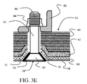
- the completed composite structure 52 with fasteners 78 installed provides conductive connection between the conical heads 80 of the fastener with the conical washers 76 which are intimately received within the conical countersinks 74 for direct connection to the conductive surface 72.
- the conical washers 76 may be eliminated and the conical heads 80 of the fasteners 78 placed in direct contact with the conductive surface 72 in the conical countersinks 74.
- Shafts 82 of the fasteners 78 are received in the holes 70 with a clearance fit.
- the fasteners 78 are secured with a nuts/collar 84 or received on threaded ends 86 of the shafts 82 to secure the composite structure 52 to another structural member 85.
- the clearance fit of the shaft 82 and hole 70 encourages current transition at the fastener head through higher resistance between the shaft and composite structure. With the induced current path through the conductive layer near the fastener head, there is negligible current density at the fastener collar or nut which reduces fuel tank sealing requirements.
- the wire mesh layer 60 provides a conductivity of at least 10 5 S/m.
- any electrical discharge attaching the head of a fastener is dissipated primarily into the wire mesh layer of the composite structure further enhancing the phenomenon of inducing current density to remain in the outer layer with high conductivity in that outer layer.
- Fabrication of the multilayer composite structure with integrated fastener-to-conductive layer surface lightning protection interconnection may be accomplished with a method illustrated in FIG. 5 .
- a tool is formed with a plurality of raised conical-shaped features, step 502, and the tool is cleaned, step 504.
- An outer protective layer of fiberglass or surfacing film is laid over the tool, step 506 and a conductive layer, wire mesh in an exemplary embodiment, is laid over the tool with the plurality of raised conical-shaped features forming a plurality of chamfered recesses in the wire-mesh conductive layer, step 508.
- An adhesive layer is laid over the wire-mesh conductive layer, step 510, or alternatively may be applied to the conductive layer prior to layup.
- Carbon-fiber reinforced plastic (CFRP) composite layers are laid over the integrated conductive layer /adhesive layer conforming to the shape of the conductive layer and tool, step 512.
- the layup is then bagged, step 514.
- the CFRP and conductive layer are co-cured as part of the layup on the tool to create the desire part such as the wing skin, step 516.
- the part is then removed from the tool, step 518, the edges trimmed, step 520, and the part inspected, step 522.
- a plurality of holes are machined through the plurality of recesses in the conductive layer and the adjoining composite layer in a manner such that the chamfered recesses in the conductive layer define countersinks extending into openings of the plurality of holes, step 524.
- a method for forming a multilayer composite structure with integrated fastener-to-conductive layer interconnection which includes laying a conductive layer over a tool having a plurality of raised conical-shaped features to form chamfered recesses in the conductive layer, laying at least one composite layer conforming to the conductive layer, co-curing the layers on the tool, and machining holes extending through the chamfered recesses in the conductive layer and the adjoining composite layer in a manner such that the chamfered recesses in the conductive layer define a countersink portions extending into the holes to expose a conductive surface of the conductive layer.
- the method further includes additional steps of inserting fasteners into the plurality of holes, where the chamfered recesses in the countersinks in the conductive layer electrically contact the conductive countersunk heads of the fasteners installed within the plurality of holes.
- the holes are sized to accommodate fasteners in a clearance fit.
- the countersink hole area is machined or finished to remove the fiberglass or other outer protective layer from the chamfered recesses, step 526.
- other approaches such as laser ablation or plasma etch may be employed to remove the outer protective layer from the surface of the chamfered recesses.
- Fasteners are inserted into the plurality of holes, step 530, with conical heads of the fasteners engaging the chamfered recesses in the countersinks in conductive layer to increase the electrical contact surface area.
- a conical washer may be inserted into the chamfered recess in each hole, step 528, prior to inserting the fastener into the hole.
- Embodiments of the disclosure may be described in the context of an aircraft manufacturing and service method 600 (method 600) as shown in FIG. 6 and an aircraft 700 as shown in FIG. 7 .
- the exemplary method 600 may include specification and design 604 of the aircraft 700 and material procurement 606.
- component and subassembly manufacturing 608 and system integration 610 of the aircraft 700 takes place.
- the aircraft 700 may go through certification and delivery 612 in order to be placed in service 614.
- routine maintenance and service 616 which may also include modification, reconfiguration, refurbishment, and so on).
- a system integrator may include without limitation any number of aircraft manufacturers and major-system subcontractors; a third party may include without limitation any number of venders, subcontractors, and suppliers; and an operator may be without limitation an airline, leasing company, military entity, service organization, and the like.
- the aircraft 700 produced by the exemplary method 600 may include an airframe 718 with a plurality of systems 720 and an interior 722.
- high-level systems 720 include one or more of a propulsion system 724, an electrical system 726, a hydraulic system 728, an environmental system 730, and an attachable/detachable segmented ordnance dispenser 732. Any number of other systems may also be included.
- an aerospace example is shown, the embodiments of the disclosure may be applied to other industries.
- Apparatus and methods embodied herein may be employed during any one or more of the stages of the production and service method 600.
- components or subassemblies corresponding to production process 608 may be fabricated or manufactured in a manner similar to components or subassemblies produced while the aircraft 700 is in service.
- one or more apparatus embodiments, method embodiments, or a combination thereof may be utilized during the production stages 608 and 610, for example, by substantially expediting assembly of or reducing the cost of an aircraft 700.
- one or more of apparatus embodiments, method embodiments, or a combination thereof may be utilized while the aircraft 700 is in service, for example and without limitation, to maintenance and service 616. Further, the disclosure comprises embodiments according to the following clauses:
Landscapes
- Engineering & Computer Science (AREA)
- Mechanical Engineering (AREA)
- Chemical & Material Sciences (AREA)
- Composite Materials (AREA)
- Aviation & Aerospace Engineering (AREA)
- General Engineering & Computer Science (AREA)
- Laminated Bodies (AREA)
- Moulding By Coating Moulds (AREA)
Abstract
Description
- Embodiments of the disclosure relate generally to the field of lightning protection of non-metallic structures and more particularly to lightning protection of aerospace structures fabricated from carbon fiber reinforced plastic (CFRP) composite systems.
- Lightning protection is a requirement for all aircraft, particularly aircraft with composite structures. Due to its high strength to weight ratio, carbon fiber reinforced plastic (CFRP) material systems are increasingly used for aerospace structures. However, since carbon fiber is 2000 times more resistive than aluminum and is embedded in a matrix that typically consists of 35-40 weight % non- conductive contents, damage from direct lightning strikes to the CFRP structures is more severe and efforts to protect the CFRP structures from lightning direct attachment have required significant attention to ensure continued airworthiness of the design. Metallic skin fasteners, particularly fasteners in composite/non-metallic wing skins, require special attention as they are more susceptible to direct lightning attachment, if unprotected, and may lead to fuel tank ignition. Common approaches for lightning protection of fastened joints in the aerospace industry include minimizing lightning current entering the fastened joints, increasing the current carrying capacity of the fastened joints, containing energy released from the fastened joints, or some combination of these approaches. Various methods and technologies have been successfully implemented with proven lightning protection performance effectiveness. However, due to their complexity, these methods have often resulted in either high part costs, high manufacturing costs or high maintenance costs.
- It is therefore desirable to provide less complex methods and designs for fastened joints in CFRP structures which maintain acceptable lightning protection at reduced costs.
- Embodiments disclosed herein provide a multilayer composite structure with integrated fastener- to-conductive layer surface lightning protection interconnections having a co-cured conductive layer, such as a wire mesh, with an inner surface and a plurality of chamfered recesses forming part of countersinks in an outer surface. One or more carbon-fiber reinforced plastic (CFRP) composite layers are disposed on the inner surface of the co-cured conductive layer and conforms to the surface shape. A plurality of holes extend through the plurality of chamfered recesses in the co-cured conductive layer and the adjoining CFRP composite layer in a manner such that the co-cured conductive layer defines a countersink portion extending into the openings of the plurality of holes. The chamfered recesses in the co-cured conductive layer increase an electrically conductive surface area that contacts conductive, metallic countersunk fasteners installed within the plurality of holes.
- A feature of one embodiment includes a carbon fiber reinforced plastic (CFRP) composite structure having a hole with a countersink and a conical washer inserted in the countersink. A fastener received with a clearance fit in the hole has a conical head conductively engaging the conical washer whereby any lightning current attaching to or conducting through the head of the fastener is dissipated in a discharge path primarily through the composite layers in an outer portion of the composite structure extending adjacent from the fastener head.
- The embodiments disclosed may be fabricated using a method of forming a multilayer composite structure with integrated fastener- to-conductive layer surface lightning protection interconnections. A glass fiber reinforced pre-impregnated layer or surfacing film is laid over a tool having a plurality of raised conical-shaped features. A conductive surface protection layer is then laid over the fiber glass or surfacing film layer to form a plurality of chamfered recesses in the co-cured conductive layer. Carbon-fiber reinforced plastic (CFRP) composite layers are then laid over the fiber glass or surfacing film layer and the conductive layer. The entire layup is then co-cured on the tool. Following cure and removal from the layup tool, a plurality of holes are machined through the plurality of recesses in the conductive layer and the adjoining composite layer in a manner such that the chamfered recesses expose the conductive layer surface and define the finished countersink dimensions. Fasteners are then inserted into the plurality of holes such that the chamfered recesses in the countersinks with the conductive layer provide the electrical connection to the countersunk heads of the metallic fasteners installed within the plurality of holes.
- The features, functions, and advantages that have been discussed can be achieved independently in various embodiments of the present disclosure or may be combined in yet other embodiments, further details of which can be seen with reference to the following description and drawings.
-
-
FIG. 1 is a section view of a prior art fastener system employing a sleeve with an interference fit at the head and shaft of a fastener; -
FIG. 2 is a section view of a first embodiment incorporating a conical washer for contact with a the top portion of a composite layup with a hole having clearance to accommodate a fastener shaft; -
FIGs. 3A - 3D show in section view an exemplary composite layup flow for a composite structural panel employing an embodiment with embedded wire mesh, as an example of a conductive surface protection layer, and optional conical contact washers; -
FIG. 3E shows a fragmentary view of the completed composite structural panel with a fastener inserted; -
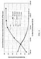
FIG. 4 is a graph showing current density in layers of a composite structure vs. conductivity of a top layer; -
FIG. 5 is a flow chart showing a manufacturing method for the composite structural panel; -
FIG. 6 is a flow chart depicting an aircraft manufacturing and service method in which the disclosed embodiments may be employed; and, -
FIG. 7 is a flow chart depicting an aircraft with which the disclosed embodiments may be employed. - Embodiments disclosed herein provide lightning and/or other forms of electrical current dissipation in a first embodiment through electrical contact between a conical washer and outer layers of a composite structure and a conical head of a fastener extending through the composite structure. A shaft of the fastener is received in the composite structure in a clearance fit hole. In a further embodiment, current dissipation is enhanced through direct electrical connection between a conductive layer co-cured in a composite structure and fasteners in the composite structure. The co-cured conductive layer extends inside a portion of the fastener holes and makes contact with heads of the fasteners or a conical washer interfacing the fastener head into the countersink after installation. The composite structure is realized by first laying down a fiber glass or surfacing film as a protective outer layer, a conductive layer such as a wire mesh, an adhesive layer (which may be integrated with the conductive layer or applied to the conductive layer prior to layup), followed by the subsequent CFRP tape layers in accordance with the structural design on a uniquely designed laminating tool with raised features. These raised features are designed to provide part of the countersink holes (typical angle of 100 degrees) for the skin fasteners that will be installed later. After curing, the laminated skin is then removed from the laminating tool, then drilled at the location of the raised features and appropriately finished to provide the countersink holes for fastener installation. Countersinking of the holes at the location of the raised features removes only the fiber glass or surfacing film outer layer on the angled surfaces of the formed indentations. In addition, to further increase the current carrying capacity of the joint, conical washers of a desired metal type having a density and thickness (as required by the design, to be discussed subsequently) may be added to the countersink hole to form electrical contacts with both the portion in the countersink holes with the conductive layer and the fastener heads. This approach allows the fasteners to make direct electrical contact either directly with the co-cured conductive layer or with the added conical washers that are in contact with the co-cured conductive layer at the countersink angled surface where lightning current transfer may occur to improve the current carrying capacity of the joint, thus negating the need for current transfer through sleeved, interference fit joints. This allows for the replacement of expensive sleeved fasteners with clearance fit fasteners, thus lowering the cost of airplane production. Clearance fit fastened joints also significantly facilitate fastener installation, and will result in reduced assembly labor and flow time.
- Referring to the drawings,
FIG. 1 shows an exemplary prior art fastener installation in which afastener 10 is received with an interference fit (fit spacing is exaggerated in the drawing for clarity of the elements) by asleeve 12 inserted in acountersunk hole 14 in amultilayer composite structure 16 such as a CFRP skin.Fastener head 18 andfastener shaft 20 are both in electrical contact with thesleeve 12 which, in turn is in electrical contact with thecomposite structure 16. Lightning current attaching to or conducting through thehead 18 of the fastener is dissipated into the composite structure throughout the length of the fastener head and shaft as indicated byarrows 22. In this example thefastener 10 is secured with a nut /collar 24 received on a threadedend 26 to secure the composite structure to another structural member 25. This discharge path results in uniform current distribution through layers in the composite structure, such as the example skin layup and higher current density at fastener collar/nut may result in enhanced fuel tank sealing requirements. - The first embodiment disclosed is shown in
FIG. 2 wherein fastener 30 having ahead 32 andshaft 34 is received in acountersunk hole 36 in aCFRP composite structure 38 such as a wing skin. A clearance fit is provided between theshaft 34 andhole 36. Anangled countersink 40 in thehole 36 provides a mating surface having an angle concentric with thefastener head 32. Aconical washer 42 is engaged between thehead 32 and thecountersink 40 providing electrical contact between the head and anouter portion 44 of thecomposite structure 38. This intimate electrical contact dissipates any electrical current conducting through thehead 32 of thefastener 30 in a discharge path (represented by arrows 46) primarily through the composite layers in theouter portion 44 of the composite structure extending adjacent from the fastener head. The clearance fit of theshaft 34 andhole 36 encourages this discharge path through lower conductive contact between the shaft and composite structure. For the exemplary embodiment, thefastener 30 is secured with a nut/collar 48, or a nut with separate washer, received on a threadedend 50 to secure thecomposite structure 38 to anotherstructural member 49. With the induced current path, there is negligible current density at the fastener collar or nut which reduces fuel tank sealing requirements as the means to contain outgassing energy from the fastened joint. - In the exemplary embodiment, the
conical washer 42, countersink in thehole 36 and thehead 32 have an angle of between 98° and 102°, nominally 100° and the conical washer has a thickness of between 0.001 and 0.005 inches. In an application with CFRP composite layers in the composite structure, a titanium fastener is employed and the conical washer is bare corrosion resistant steel (CRES) to provide the desired conductivity. - For the second disclosed embodiment,
FIGs 3A - 3E illustrate a desired structure for an exemplary wing skin integral to a fuel tank in an aircraft. Amultilayer composite structure 52 with integrated fastener-to-conductive layer surface protection interconnection is formed by employing alaminating tool 54, as seen inFIG. 3A , having a plurality of raised conical-shaped features orprotrusions 56 positioned at desired fastener locations. A fiberglass or surfacingfilm layer 58 is placed on the tool to initiate the layup with the fiberglass or surfacing layer conforming to each of the conical shaped features 56. A conductive layer such as awire mesh 60 is laid up over the fiberglass or surfacingfilm layer 58 with anouter surface 59 adjacent the fiberglass or surfacing film layer. For an exemplary embodiment the wire mesh layer is an expanded metal foil, such as copper, nickel or aluminum, with thickness ranging from 0.001 to 0.005 inch. Anadhesive layer 62 is placed or applied over thewire mesh layer 60 and CFRP tape layers 64 for the composite structure such as an aircraft wing skin are laid up over aninner surface 61 of thewire mesh layer 60 covered by the adhesive layer. For the example embodiment the adhesive layer is epoxy based and has a film areal weight of 0.0200 ± 0.0050 lb/ft2.In alternative embodiments, theadhesive layer 62 may be applied to thewire mesh layer 60 prior to layup with the other elements of the composite structure. Curing of the layup is then accomplished on thelaminating tool 54. - The cured
layup 66 seen inFIG. 3B is removed from thelaminating tool 54. The layup provides preshaped conical chamfered recesses 68 corresponding to desired countersinks for fasteners at each of the desired locations. A plurality ofholes 70 through which fasteners may be inserted are then drilled, finished or otherwise machined through therecesses 68 as seen inFIG. 3C . The fiberglass in the chamfered recesses 68 is then removed as shown inFIG. 3D leaving each chamfered recesses to expose theconductive surface 72 asconical countersinks 74 extending into an opening of eachhole 70. The extension of the conductive layer into the recesses, provides an electrically conductive surface area in the countersink. For the embodiment shown, the chamfered recess results in parallel contact of the conductive layer over the entire length of the fastener head while the overall thickness of the wire mesh conductive layer spaced over the surface of the composite structure between the holes may remain thin for weight considerations. Accordingly, a multilayer composite structure with integrated fastener-to-conductive layer interconnection is provided, comprising a conductive layer having a plurality of chamfered recesses forming countersinks in an outer surface of the conductive layer, one or more carbon fiber reinforced plastic (CFRP) composite layers conforming to an inner surface of the conductive layer, and holes extending through the chamfered recesses in the conductive layer and the adjoining CFRP composite layer in a manner such that the conductive layer defines a countersink portion extending into openings of the holes. The chamfered recesses in the conductive layer thereby provide an electrically conductive surface area that enables electrical contact with electrically conductive countersunk fasteners that may be installed within the plurality of holes.Conical washers 76 may then be inserted into thecountersinks 74. - As seen in
FIG. 3E , the completedcomposite structure 52 withfasteners 78 installed provides conductive connection between theconical heads 80 of the fastener with theconical washers 76 which are intimately received within theconical countersinks 74 for direct connection to theconductive surface 72. In alternative embodiments, theconical washers 76 may be eliminated and the conical heads 80 of thefasteners 78 placed in direct contact with theconductive surface 72 in theconical countersinks 74.Shafts 82 of thefasteners 78 are received in theholes 70 with a clearance fit. For the embodiment shown, thefasteners 78 are secured with a nuts/collar 84 or received on threaded ends 86 of theshafts 82 to secure thecomposite structure 52 to anotherstructural member 85. The clearance fit of theshaft 82 andhole 70 encourages current transition at the fastener head through higher resistance between the shaft and composite structure. With the induced current path through the conductive layer near the fastener head, there is negligible current density at the fastener collar or nut which reduces fuel tank sealing requirements. - As seen in the graph provided in
FIG. 4 , for a composite structure having an outer layer with adjoining layers of CFRP composite in 0 °, 45°, 90° and -45°, enhancing the conductivity of the top or outer layer in the composite structure having exposed fastener heads, as seen intrace 402, results in significantly reduced current density in inner composite layers as seen bytraces wire mesh layer 60 provides a conductivity of at least 105 S/m. With the intimate conductive contact provided either directly from the conical head of the fasteners or through a conical washer into the chamfered surface of the countersink provided in the wire mesh surrounding each hole, any electrical discharge attaching the head of a fastener is dissipated primarily into the wire mesh layer of the composite structure further enhancing the phenomenon of inducing current density to remain in the outer layer with high conductivity in that outer layer. - Fabrication of the multilayer composite structure with integrated fastener-to-conductive layer surface lightning protection interconnection may be accomplished with a method illustrated in
FIG. 5 . A tool is formed with a plurality of raised conical-shaped features,step 502, and the tool is cleaned,step 504. An outer protective layer of fiberglass or surfacing film is laid over the tool,step 506 and a conductive layer, wire mesh in an exemplary embodiment, is laid over the tool with the plurality of raised conical-shaped features forming a plurality of chamfered recesses in the wire-mesh conductive layer,step 508. An adhesive layer is laid over the wire-mesh conductive layer,step 510, or alternatively may be applied to the conductive layer prior to layup. Carbon-fiber reinforced plastic (CFRP) composite layers are laid over the integrated conductive layer /adhesive layer conforming to the shape of the conductive layer and tool,step 512. The layup is then bagged,step 514. The CFRP and conductive layer are co-cured as part of the layup on the tool to create the desire part such as the wing skin,step 516. The part is then removed from the tool, step 518, the edges trimmed,step 520, and the part inspected,step 522. A plurality of holes are machined through the plurality of recesses in the conductive layer and the adjoining composite layer in a manner such that the chamfered recesses in the conductive layer define countersinks extending into openings of the plurality of holes,step 524. Accordingly, a method is provided for forming a multilayer composite structure with integrated fastener-to-conductive layer interconnection, which includes laying a conductive layer over a tool having a plurality of raised conical-shaped features to form chamfered recesses in the conductive layer, laying at least one composite layer conforming to the conductive layer, co-curing the layers on the tool, and machining holes extending through the chamfered recesses in the conductive layer and the adjoining composite layer in a manner such that the chamfered recesses in the conductive layer define a countersink portions extending into the holes to expose a conductive surface of the conductive layer. The method further includes additional steps of inserting fasteners into the plurality of holes, where the chamfered recesses in the countersinks in the conductive layer electrically contact the conductive countersunk heads of the fasteners installed within the plurality of holes. The holes are sized to accommodate fasteners in a clearance fit. The countersink hole area is machined or finished to remove the fiberglass or other outer protective layer from the chamfered recesses,step 526. In alternative embodiments, other approaches such as laser ablation or plasma etch may be employed to remove the outer protective layer from the surface of the chamfered recesses. Fasteners are inserted into the plurality of holes,step 530, with conical heads of the fasteners engaging the chamfered recesses in the countersinks in conductive layer to increase the electrical contact surface area. A conical washer may be inserted into the chamfered recess in each hole,step 528, prior to inserting the fastener into the hole. - Embodiments of the disclosure may be described in the context of an aircraft manufacturing and service method 600 (method 600) as shown in
FIG. 6 and anaircraft 700 as shown inFIG. 7 . During pre-production, theexemplary method 600 may include specification anddesign 604 of theaircraft 700 andmaterial procurement 606. During production, component andsubassembly manufacturing 608 andsystem integration 610 of theaircraft 700 takes place. Thereafter, theaircraft 700 may go through certification anddelivery 612 in order to be placed inservice 614. While in service by a customer, theaircraft 700 is scheduled for routine maintenance and service 616 (which may also include modification, reconfiguration, refurbishment, and so on). - Each of the processes of
method 600 may be performed or carried out by a system integrator, a third party, and/or an operator (e.g., a customer). For the purposes of this description, a system integrator may include without limitation any number of aircraft manufacturers and major-system subcontractors; a third party may include without limitation any number of venders, subcontractors, and suppliers; and an operator may be without limitation an airline, leasing company, military entity, service organization, and the like. - As shown in
FIG. 7 , theaircraft 700 produced by theexemplary method 600 may include anairframe 718 with a plurality ofsystems 720 and an interior 722. Examples of high-level systems 720 include one or more of apropulsion system 724, anelectrical system 726, ahydraulic system 728, anenvironmental system 730, and an attachable/detachablesegmented ordnance dispenser 732. Any number of other systems may also be included. Although an aerospace example is shown, the embodiments of the disclosure may be applied to other industries. - Apparatus and methods embodied herein may be employed during any one or more of the stages of the production and
service method 600. For example, components or subassemblies corresponding toproduction process 608 may be fabricated or manufactured in a manner similar to components or subassemblies produced while theaircraft 700 is in service. In addition, one or more apparatus embodiments, method embodiments, or a combination thereof may be utilized during the production stages 608 and 610, for example, by substantially expediting assembly of or reducing the cost of anaircraft 700. Similarly, one or more of apparatus embodiments, method embodiments, or a combination thereof may be utilized while theaircraft 700 is in service, for example and without limitation, to maintenance andservice 616.
Further, the disclosure comprises embodiments according to the following clauses: -
Clause 1. A multilayer composite structure with integrated fastener-to-conductive layer surface lightning protection interconnection comprising:- a conductive layer, having an inner surface and a plurality of chamfered recesses forming countersinks in an outer surface; and
- one or more carbon fiber reinforced plastic (CFRP) composite layers disposed on and conforming to the inner surface of the conductive layer; and
whereby the chamfered recesses in the conductive layer provide an electrically conductive surface area that contacts conductive countersunk fasteners installed within the plurality of holes. - Clause 2. The multilayer composite structure with integrated fastener-to-conductive layer surface lightning protection interconnection as defined in
Clause 1 further comprising a fiberglass or surfacing film layer cocured over the outer surface of the conductive layer. - Clause 3. The multilayer composite structure with integrated fastener-to-conductive layer surface lightning protection interconnection as defined in
Clause 1 or 2 further comprising an adhesive layer integrated with the conductive layer between the conductive layer and the CFRP composite layer, said conductive layer, adhesive layer and the CFRP composite layer cocured on a shaped tool. - Clause 4. The multilayer composite structure with integrated fastener-to-conductive layer surface lightning protection interconnection as defined in any preceding Clause further comprising a plurality of conical washers inserted into the chamfered recesses.
- Clause 5. The multilayer composite structure with integrated fastener-to-conductive layer surface lightning protection interconnection as defined in Clause 4 wherein a conical head of each fastener conductively engages each conical washer.
- Clause 6. The multilayer composite structure with integrated fastener- to-conductive layer surface lightning protection interconnection as defined in any preceding Clause wherein the plurality of holes are sized to receive the plurality of fasteners in a clearance fit.
- Clause 7. The multilayer composite structure with integrated fastener- to-conductive layer surface lightning protection interconnection as defined in any preceding Clause wherein the conductive layer comprises a wire mesh.
- Clause 8. The multilayer composite structure with integrated fastener- to-conductive layer surface lightning protection interconnection as defined in Clause 7 wherein the wire mesh comprises an expanded metal foil, selected from the set of copper, nickel or aluminum.
- Clause 9. The multilayer composite structure with integrated fastener- to-conductive layer surface lightning protection interconnection as defined in Clause 8 wherein the expanded metal foil has thickness from 0.001 to 0.005 inch.
-
Clause 10. An integrated fastener surface lightning protection interconnection comprising:- a carbon fiber reinforced plastic (CFRP) composite structure having a hole with a countersink;
- a conical washer inserted in the countersink;
- a fastener received with a clearance fit in the hole, a conical head of the fastener conductively engaging the conical washer whereby any electrical discharge attaching to the head of the fastener is dissipated in a discharge path primarily through the composite layers in an outer portion of the composite structure extending adjacent from the fastener head.
- Clause 11. The integrated fastener surface lightning protection interconnection as defined in
Clause 10 wherein the fastener head is titanium and the conical washer is corrosion resistant steel (CRES). -
Clause 12. The integrated fastener surface lightning protection interconnection as defined inClause 10 or 11 wherein the conical washer has a thickness of 0.001 to 0.005 inch - Clause 13. A method of forming a multilayer composite structure with integrated fastener- to-conductive layer surface lightning protection interconnection comprising the steps of:
- laying a conductive layer over a tool having a plurality of raised conical-shaped features, to form a plurality of chamfered recesses in the wire-mesh conductive layer;
- laying at least one carbon-fiber reinforced plastic (CFRP) composite layer over the conductive layer;
- cocuring the CFRP and conductive layer on the tool;
- machining a plurality of holes through the plurality of recesses in the conductive layer and the adjoining composite layer in a manner such that the chamfered recesses in the conductive layer define countersinks extending into openings of the plurality of holes and exposes a conductive surface of the conductive layer; and,
- inserting fasteners into the plurality of holes;
-
Clause 14. The method as defined in Clause 13 further comprising laying a fiberglass layer on the tool prior to laying the conductive layer. - Clause 15. The method as defined in
Clause 13 or 14 wherein the conductive layer comprises a wire mesh and further comprising laying an adhesive layer between the wire mesh and the at least one CFRP layer. -
Clause 16. The method as defined in any of Clauses 13 to 15 further comprising inserting conical washers into the chamfered recesses prior to inserting the fasteners into the plurality of holes. - Clause 17. The method as defined in any of Clauses 13 to 16 wherein the step of machining a plurality of holes comprises machining a plurality of holes for clearance fit of fasteners.
-
Clause 18. The method as defined in any of Clauses 13 to 17 further comprising forming the tool with a plurality of raised conical-shaped features having a chamfer angle of between 98° and 102°. - Clause 19. The method as defined in any of Clauses 15 to 18 wherein the wire mesh wherein the conical washer has a thickness of between 0.001 and 0.005 inches.
-
Clause 20. The method as defined in any ofClauses 16 to 19 wherein the conical washer has a thickness of between 0.001 and 0.005 inches. - Having now described various embodiments of the disclosure in detail as required by the patent statutes, those skilled in the art will recognize modifications and substitutions to the specific embodiments disclosed herein. Such modifications are within the scope and intent of the present disclosure as defined in the following claims.
Claims (14)
- A multilayer composite structure (52) with integrated fastener-to-conductive layer surface lightning protection interconnection comprising:a conductive layer (72), having an inner surface (61) and a plurality of chamfered recesses (68) forming countersinks (74) in an outer surface (59); andone or more carbon fiber reinforced plastic (CFRP) composite layers disposed on and conforming to the inner surface (61) of the conductive layer (72); anda plurality of holes (70) extending through the plurality of chamfered recesses (68) in the conductive layer (72) and the adjoining CFRP composite layer in a manner such that the conductive layer (72) defines a countersink portion extending into openings of the plurality of holes (70),whereby the chamfered recesses (68) in the conductive layer (72) provide an electrically conductive surface area that contacts conductive countersunk fasteners installed within the plurality of holes (70).
- The multilayer composite structure (52) with integrated fastener-to-conductive layer surface lightning protection interconnection as defined in claim 1 further comprising a fiberglass or surfacing film layer (58) cocured over the outer surface (59) of the conductive layer (72).
- The multilayer composite structure (52) with integrated fastener-to-conductive layer surface lightning protection interconnection as defined in any of claims 1-2 further comprising an adhesive layer (62) integrated with the conductive layer (72) between the conductive layer (72) and the CFRP composite layer, said conductive layer (72), adhesive layer (62) and the CFRP composite layer cocured on a shaped tool (54).
- The multilayer composite structure (52) with integrated fastener-to-conductive layer surface lightning protection interconnection as defined in any preceding claim further comprising a plurality of conical washers (76) inserted into the chamfered recesses (68).
- The multilayer composite structure (52) with integrated fastener-to-conductive layer surface lightning protection interconnection as defined in claim 4 wherein a conical head (80) of each fastener conductively engages each conical washer (76).
- The multilayer composite structure (52) with integrated fastener- to-conductive layer surface lightning protection interconnection as defined in any of claims 1-5 wherein the plurality of holes (70) are sized to receive the plurality of fasteners (78) in a clearance fit.
- The multilayer composite structure (52) with integrated fastener- to-conductive layer surface lightning protection interconnection as defined in any of claims 1-6 wherein the conductive layer (72) comprises a wire mesh (60).
- The multilayer composite structure (52) with integrated fastener- to-conductive layer surface lightning protection interconnection as defined in claim 7 wherein the wire mesh (60) comprises an expanded metal foil, selected from the set of copper, nickel or aluminum.
- A method of forming a multilayer composite structure (52) with integrated fastener- to-conductive layer surface lightning protection interconnection comprising the steps of:laying a conductive layer (72) over a tool (54) having a plurality of raised conical-shaped features (56), to form a plurality of chamfered recesses (68) in the wire-mesh (60) conductive layer (72);laying at least one carbon-fiber reinforced plastic (CFRP) composite layer over the conductive layer (72);cocuring the CFRP and conductive layer (72) on the tool (54);machining a plurality of holes (70) through the plurality of recesses (68) in the conductive layer (72) and the adjoining composite layer in a manner such that the chamfered recesses (68) in the conductive layer (72) define countersinks (74) extending into openings of the plurality of holes (70) and exposes a conductive surface of the conductive layer (72); and,inserting fasteners (78) into the plurality of holes (70);wherein the chamfered recesses (68) in the countersinks (74) in the conductive layer (72) electrically contacts the conductive countersunk heads of the fasteners (78) installed within the plurality of holes (70).
- The method as defined in claim 9 further comprising laying a fiberglass layer (58) on the tool (54) prior to laying the conductive layer (72).
- The method as defined in claim 9 or 10 wherein the conductive layer (72) comprises a wire mesh (60) and further comprising laying an adhesive layer (62) between the wire mesh (60) and the at least one CFRP layer.
- The method as defined in any of claims 9 to 11 further comprising inserting conical washers (76) into the chamfered recesses (68) prior to inserting the fasteners (78) into the plurality of holes (70).
- The method as defined in any of claims 9-12 wherein the step of machining a plurality of holes (70) comprises machining a plurality of holes (70) for clearance fit of fasteners (78).
- The method as defined in any of claims 9-13 further comprising forming the tool (54) with a plurality of raised conical-shaped features (56) having a chamfer angle of between 98° and 102°.
Applications Claiming Priority (1)
| Application Number | Priority Date | Filing Date | Title |
|---|---|---|---|
| US14/875,297 US9912137B2 (en) | 2015-10-05 | 2015-10-05 | Methods for diverting lightning current from skin fasteners in composite, non-metallic structures |
Publications (2)
| Publication Number | Publication Date |
|---|---|
| EP3153410A1 true EP3153410A1 (en) | 2017-04-12 |
| EP3153410B1 EP3153410B1 (en) | 2020-06-17 |
Family
ID=57137806
Family Applications (1)
| Application Number | Title | Priority Date | Filing Date |
|---|---|---|---|
| EP16189302.9A Active EP3153410B1 (en) | 2015-10-05 | 2016-09-16 | Methods for diverting lightning current from skin fasteners in composite, non-metallic structures |
Country Status (8)
| Country | Link |
|---|---|
| US (1) | US9912137B2 (en) |
| EP (1) | EP3153410B1 (en) |
| JP (1) | JP6941422B2 (en) |
| CN (1) | CN106560399B (en) |
| AU (1) | AU2016204482B2 (en) |
| BR (1) | BR102016018329B1 (en) |
| CA (1) | CA2934731C (en) |
| RU (1) | RU2711560C2 (en) |
Cited By (5)
| Publication number | Priority date | Publication date | Assignee | Title |
|---|---|---|---|---|
| EP3511579A1 (en) * | 2018-01-15 | 2019-07-17 | Subaru Corporation | Fastening structure |
| EP3909861A1 (en) * | 2017-12-11 | 2021-11-17 | The Boeing Company | Lightning protection in aircrafts constructed with carbon fiber reinforced plastic |
| WO2021260376A1 (en) * | 2020-06-24 | 2021-12-30 | Stalcom Automotive Technologies Limited | Sheet material |
| US20220135200A1 (en) * | 2020-11-02 | 2022-05-05 | Projets et Réalisations Sàrl | Aircraft fuselage configured to offer the passengers a totally panoramic view of the outside |
| EP4302987A1 (en) * | 2022-07-07 | 2024-01-10 | Airbus Operations Limited | Structure with lightning-strike protection layer |
Families Citing this family (20)
| Publication number | Priority date | Publication date | Assignee | Title |
|---|---|---|---|---|
| US10878139B2 (en) * | 2015-07-27 | 2020-12-29 | The Boeing Company | Composite joint optimization |
| CN107323648A (en) * | 2017-06-22 | 2017-11-07 | 中国航空工业集团公司沈阳飞机设计研究所 | The conduction metalolic network of composite airplane |
| US10710352B2 (en) * | 2017-07-11 | 2020-07-14 | The Boeing Company | Structural pre-cured repair patch for repair to highly loaded primary and secondary structural components |
| US11338899B2 (en) * | 2018-04-05 | 2022-05-24 | The Boeing Company | Joint for a metal airplane skin using metal matrix composite |
| US10899468B2 (en) * | 2018-09-27 | 2021-01-26 | The Boeing Company | Washer assembly with seal for lightning-protection fasteners and method of manufacture |
| US11001393B2 (en) | 2018-09-27 | 2021-05-11 | The Boeing Company | Washer assembly with seal for lightning-protection fasteners and method of use |
| CN109783849B (en) * | 2018-12-06 | 2021-11-23 | 西安交通大学 | Method for calculating damage of carbon fiber composite material under action of single fast-rising lightning current component |
| CN109783848B (en) * | 2018-12-06 | 2022-04-05 | 西安交通大学 | Damage calculation method of carbon fiber composites under the action of a single slowly rising lightning current component |
| CN109605783A (en) * | 2018-12-10 | 2019-04-12 | 河北汉光重工有限责任公司 | A method of solving composite material structural member conducting continuity |
| CN110065620A (en) * | 2019-04-12 | 2019-07-30 | 西安飞机工业(集团)有限责任公司 | A kind of composite walls board connecting structure |
| US11396900B2 (en) * | 2019-05-10 | 2022-07-26 | The Boeing Company | Fastener and methods of manufacturing and use |
| CN112072335B (en) * | 2020-09-25 | 2022-06-24 | 中国直升机设计研究所 | Conductive structure between composite material structural members and conductive processing method |
| CN113928576B (en) * | 2021-11-19 | 2023-09-01 | 中国直升机设计研究所 | Helicopter composite material lightning protection capability repairing method |
| US12589881B2 (en) | 2022-03-30 | 2026-03-31 | The Boeing Company | Co-cured UV/visible light-resistant coated composite material for aircraft wing fuel tank assembly |
| US12466574B2 (en) | 2022-03-30 | 2025-11-11 | The Boeing Company | Co-cured UV-resistant fiberglass coated composite material for aircraft wing fuel tank assembly |
| US12350892B2 (en) | 2022-03-30 | 2025-07-08 | The Boeing Company | Co-cured UV/visible light-resistant fiberglass coated composite material for aircraft fuselage assembly |
| US12377949B2 (en) | 2022-03-30 | 2025-08-05 | The Boeing Company | Co-cured UV/visible light-resistant coated composite material for aircraft fuselage assembly |
| US12350915B2 (en) | 2022-03-30 | 2025-07-08 | The Boeing Company | Co-cured UV/visible light-resistant composite material for structural aircraft assembly |
| CN115648668B (en) * | 2022-10-26 | 2025-08-29 | 河北中电华拓科技有限公司 | A carbon fiber composite material electrical conduction structure and its manufacturing method |
| CN116053812A (en) * | 2022-12-19 | 2023-05-02 | 中国直升机设计研究所 | Conductive method and structure between composite movable cover and body fixed structure |
Citations (5)
| Publication number | Priority date | Publication date | Assignee | Title |
|---|---|---|---|---|
| US3755713A (en) * | 1972-07-25 | 1973-08-28 | Boeing Co | Electrically conductive surface for aircraft |
| FR2765066A1 (en) * | 1997-06-20 | 1998-12-24 | Aerospatiale | ANTI-SPARK STRUCTURE, ESPECIALLY FOR AIRCRAFT |
| US20040246651A1 (en) * | 2003-06-06 | 2004-12-09 | Airbus Espana S.L. | Lightning strike protection system for aircraft fuel tanks made of low electrical conductivity composite material |
| US20090258220A1 (en) * | 2008-04-14 | 2009-10-15 | The Boeing Company | System and method for fabrication of integrated lightning strike protection material |
| US20110174536A1 (en) * | 2008-10-03 | 2011-07-21 | Robert Samuel Wilson | Fibre reinforced composite structures and method of manufacture |
Family Cites Families (11)
| Publication number | Priority date | Publication date | Assignee | Title |
|---|---|---|---|---|
| US8246770B2 (en) * | 2005-09-06 | 2012-08-21 | The Boeing Company | Copper grid repair technique for lightning strike protection |
| US7686905B2 (en) * | 2005-09-06 | 2010-03-30 | The Boeing Company | Copper grid repair technique for lightning strike protection |
| US7599164B2 (en) | 2006-12-07 | 2009-10-06 | The Boeing Company | Lightning protection system for aircraft composite structure |
| US7898785B2 (en) * | 2006-12-07 | 2011-03-01 | The Boeing Company | Lightning protection system for an aircraft composite structure |
| JP4719203B2 (en) * | 2007-09-28 | 2011-07-06 | 三菱重工業株式会社 | Lightning fastener |
| FR2924685B1 (en) * | 2007-12-11 | 2010-03-19 | Airbus France | PARAFOUDRE AND AIRCRAFT SYSTEM COMPRISING SUCH A SYSTEM. |
| JP5055178B2 (en) * | 2008-03-24 | 2012-10-24 | 三菱重工業株式会社 | Aircraft assembly |
| CA2758797C (en) * | 2009-04-17 | 2018-06-12 | 3M Innovative Properties Company | Lightning protection sheet with patterned conductor |
| KR101420155B1 (en) * | 2009-10-22 | 2014-07-16 | 알코아 인코포레이티드 | Enhanced conductivity sleeved fastener and method for making same |
| EP2501975B1 (en) * | 2009-11-20 | 2015-01-07 | Alcoa Inc. | Lockwireless anti-rotation fitting |
| RU2466912C1 (en) * | 2011-07-01 | 2012-11-20 | Федеральное государственное бюджетное образовательное учреждение высшего профессионального образования "Национальный исследовательский университет "МЭИ" | Anti-lightning device for aircraft nose cone and antenna accommodated therein |
-
2015
- 2015-10-05 US US14/875,297 patent/US9912137B2/en active Active
-
2016
- 2016-06-28 RU RU2016125789A patent/RU2711560C2/en active
- 2016-06-29 CA CA2934731A patent/CA2934731C/en active Active
- 2016-06-29 AU AU2016204482A patent/AU2016204482B2/en active Active
- 2016-08-09 BR BR102016018329-4A patent/BR102016018329B1/en active IP Right Grant
- 2016-08-10 CN CN201610653397.3A patent/CN106560399B/en active Active
- 2016-09-16 EP EP16189302.9A patent/EP3153410B1/en active Active
- 2016-09-30 JP JP2016193484A patent/JP6941422B2/en active Active
Patent Citations (5)
| Publication number | Priority date | Publication date | Assignee | Title |
|---|---|---|---|---|
| US3755713A (en) * | 1972-07-25 | 1973-08-28 | Boeing Co | Electrically conductive surface for aircraft |
| FR2765066A1 (en) * | 1997-06-20 | 1998-12-24 | Aerospatiale | ANTI-SPARK STRUCTURE, ESPECIALLY FOR AIRCRAFT |
| US20040246651A1 (en) * | 2003-06-06 | 2004-12-09 | Airbus Espana S.L. | Lightning strike protection system for aircraft fuel tanks made of low electrical conductivity composite material |
| US20090258220A1 (en) * | 2008-04-14 | 2009-10-15 | The Boeing Company | System and method for fabrication of integrated lightning strike protection material |
| US20110174536A1 (en) * | 2008-10-03 | 2011-07-21 | Robert Samuel Wilson | Fibre reinforced composite structures and method of manufacture |
Cited By (8)
| Publication number | Priority date | Publication date | Assignee | Title |
|---|---|---|---|---|
| EP3909861A1 (en) * | 2017-12-11 | 2021-11-17 | The Boeing Company | Lightning protection in aircrafts constructed with carbon fiber reinforced plastic |
| US11292611B2 (en) | 2017-12-11 | 2022-04-05 | The Boeing Company | Lightning protection in aircrafts constructed with carbon fiber reinforced plastic |
| EP3511579A1 (en) * | 2018-01-15 | 2019-07-17 | Subaru Corporation | Fastening structure |
| US11873113B2 (en) | 2018-01-15 | 2024-01-16 | Subaru Corporation | Fastening structure |
| WO2021260376A1 (en) * | 2020-06-24 | 2021-12-30 | Stalcom Automotive Technologies Limited | Sheet material |
| US20220135200A1 (en) * | 2020-11-02 | 2022-05-05 | Projets et Réalisations Sàrl | Aircraft fuselage configured to offer the passengers a totally panoramic view of the outside |
| US11713103B2 (en) * | 2020-11-02 | 2023-08-01 | Projets et Réalisations Sàrl | Aircraft fuselage configured to offer the passengers a totally panoramic view of the outside |
| EP4302987A1 (en) * | 2022-07-07 | 2024-01-10 | Airbus Operations Limited | Structure with lightning-strike protection layer |
Also Published As
| Publication number | Publication date |
|---|---|
| JP6941422B2 (en) | 2021-09-29 |
| EP3153410B1 (en) | 2020-06-17 |
| AU2016204482A1 (en) | 2017-04-20 |
| US9912137B2 (en) | 2018-03-06 |
| CA2934731C (en) | 2021-03-09 |
| CN106560399A (en) | 2017-04-12 |
| RU2016125789A (en) | 2018-01-10 |
| JP2017071388A (en) | 2017-04-13 |
| RU2711560C2 (en) | 2020-01-17 |
| AU2016204482B2 (en) | 2020-10-08 |
| US20170098930A1 (en) | 2017-04-06 |
| CN106560399B (en) | 2021-08-24 |
| CA2934731A1 (en) | 2017-04-05 |
| BR102016018329B1 (en) | 2021-10-26 |
| BR102016018329A2 (en) | 2017-07-25 |
Similar Documents
| Publication | Publication Date | Title |
|---|---|---|
| US9912137B2 (en) | Methods for diverting lightning current from skin fasteners in composite, non-metallic structures | |
| US7898785B2 (en) | Lightning protection system for an aircraft composite structure | |
| US10595428B2 (en) | Integrated wiring system for composite structures | |
| JP6971080B2 (en) | Wings and manufacturing method | |
| US11629411B2 (en) | Structural arrangement with a fiber reinforced polymer component and a cold gas sprayed electrically conductive layer | |
| US8986816B2 (en) | Decorative decal system for an aircraft | |
| EP3909861B1 (en) | Lightning protection in aircrafts constructed with carbon fiber reinforced plastic | |
| US20160068275A1 (en) | Locking member with sealing insert and channel | |
| CA2890769C (en) | Methods and apparatus for use in forming a lightning protection system | |
| US20240009961A1 (en) | Structure with lightning-strike protection layer | |
| EP3299297B1 (en) | A rotary wing aircraft with a structural arrangement that comprises an electrically conductive connection | |
| US20250376253A1 (en) | Composite fuselage barrel with improved eme protection and method of making thereof |
Legal Events
| Date | Code | Title | Description |
|---|---|---|---|
| PUAI | Public reference made under article 153(3) epc to a published international application that has entered the european phase |
Free format text: ORIGINAL CODE: 0009012 |
|
| STAA | Information on the status of an ep patent application or granted ep patent |
Free format text: STATUS: REQUEST FOR EXAMINATION WAS MADE |
|
| 17P | Request for examination filed |
Effective date: 20160916 |
|
| AK | Designated contracting states |
Kind code of ref document: A1 Designated state(s): AL AT BE BG CH CY CZ DE DK EE ES FI FR GB GR HR HU IE IS IT LI LT LU LV MC MK MT NL NO PL PT RO RS SE SI SK SM TR |
|
| AX | Request for extension of the european patent |
Extension state: BA ME |
|
| STAA | Information on the status of an ep patent application or granted ep patent |
Free format text: STATUS: EXAMINATION IS IN PROGRESS |
|
| 17Q | First examination report despatched |
Effective date: 20190415 |
|
| GRAP | Despatch of communication of intention to grant a patent |
Free format text: ORIGINAL CODE: EPIDOSNIGR1 |
|
| STAA | Information on the status of an ep patent application or granted ep patent |
Free format text: STATUS: GRANT OF PATENT IS INTENDED |
|
| INTG | Intention to grant announced |
Effective date: 20200120 |
|
| GRAS | Grant fee paid |
Free format text: ORIGINAL CODE: EPIDOSNIGR3 |
|
| GRAJ | Information related to disapproval of communication of intention to grant by the applicant or resumption of examination proceedings by the epo deleted |
Free format text: ORIGINAL CODE: EPIDOSDIGR1 |
|
| GRAL | Information related to payment of fee for publishing/printing deleted |
Free format text: ORIGINAL CODE: EPIDOSDIGR3 |
|
| STAA | Information on the status of an ep patent application or granted ep patent |
Free format text: STATUS: EXAMINATION IS IN PROGRESS |
|
| INTC | Intention to grant announced (deleted) | ||
| GRAR | Information related to intention to grant a patent recorded |
Free format text: ORIGINAL CODE: EPIDOSNIGR71 |
|
| STAA | Information on the status of an ep patent application or granted ep patent |
Free format text: STATUS: GRANT OF PATENT IS INTENDED |
|
| GRAA | (expected) grant |
Free format text: ORIGINAL CODE: 0009210 |
|
| STAA | Information on the status of an ep patent application or granted ep patent |
Free format text: STATUS: THE PATENT HAS BEEN GRANTED |
|
| INTG | Intention to grant announced |
Effective date: 20200507 |
|
| AK | Designated contracting states |
Kind code of ref document: B1 Designated state(s): AL AT BE BG CH CY CZ DE DK EE ES FI FR GB GR HR HU IE IS IT LI LT LU LV MC MK MT NL NO PL PT RO RS SE SI SK SM TR |
|
| REG | Reference to a national code |
Ref country code: GB Ref legal event code: FG4D |
|
| REG | Reference to a national code |
Ref country code: CH Ref legal event code: EP |
|
| REG | Reference to a national code |
Ref country code: IE Ref legal event code: FG4D |
|
| REG | Reference to a national code |
Ref country code: DE Ref legal event code: R096 Ref document number: 602016038126 Country of ref document: DE |
|
| REG | Reference to a national code |
Ref country code: AT Ref legal event code: REF Ref document number: 1281032 Country of ref document: AT Kind code of ref document: T Effective date: 20200715 |
|
| PG25 | Lapsed in a contracting state [announced via postgrant information from national office to epo] |
Ref country code: LT Free format text: LAPSE BECAUSE OF FAILURE TO SUBMIT A TRANSLATION OF THE DESCRIPTION OR TO PAY THE FEE WITHIN THE PRESCRIBED TIME-LIMIT Effective date: 20200617 Ref country code: GR Free format text: LAPSE BECAUSE OF FAILURE TO SUBMIT A TRANSLATION OF THE DESCRIPTION OR TO PAY THE FEE WITHIN THE PRESCRIBED TIME-LIMIT Effective date: 20200918 Ref country code: FI Free format text: LAPSE BECAUSE OF FAILURE TO SUBMIT A TRANSLATION OF THE DESCRIPTION OR TO PAY THE FEE WITHIN THE PRESCRIBED TIME-LIMIT Effective date: 20200617 Ref country code: NO Free format text: LAPSE BECAUSE OF FAILURE TO SUBMIT A TRANSLATION OF THE DESCRIPTION OR TO PAY THE FEE WITHIN THE PRESCRIBED TIME-LIMIT Effective date: 20200917 Ref country code: SE Free format text: LAPSE BECAUSE OF FAILURE TO SUBMIT A TRANSLATION OF THE DESCRIPTION OR TO PAY THE FEE WITHIN THE PRESCRIBED TIME-LIMIT Effective date: 20200617 |
|
| REG | Reference to a national code |
Ref country code: LT Ref legal event code: MG4D |
|
| REG | Reference to a national code |
Ref country code: NL Ref legal event code: MP Effective date: 20200617 |
|
| PG25 | Lapsed in a contracting state [announced via postgrant information from national office to epo] |
Ref country code: BG Free format text: LAPSE BECAUSE OF FAILURE TO SUBMIT A TRANSLATION OF THE DESCRIPTION OR TO PAY THE FEE WITHIN THE PRESCRIBED TIME-LIMIT Effective date: 20200917 Ref country code: RS Free format text: LAPSE BECAUSE OF FAILURE TO SUBMIT A TRANSLATION OF THE DESCRIPTION OR TO PAY THE FEE WITHIN THE PRESCRIBED TIME-LIMIT Effective date: 20200617 Ref country code: HR Free format text: LAPSE BECAUSE OF FAILURE TO SUBMIT A TRANSLATION OF THE DESCRIPTION OR TO PAY THE FEE WITHIN THE PRESCRIBED TIME-LIMIT Effective date: 20200617 Ref country code: LV Free format text: LAPSE BECAUSE OF FAILURE TO SUBMIT A TRANSLATION OF THE DESCRIPTION OR TO PAY THE FEE WITHIN THE PRESCRIBED TIME-LIMIT Effective date: 20200617 |
|
| REG | Reference to a national code |
Ref country code: AT Ref legal event code: MK05 Ref document number: 1281032 Country of ref document: AT Kind code of ref document: T Effective date: 20200617 |
|
| PG25 | Lapsed in a contracting state [announced via postgrant information from national office to epo] |
Ref country code: AL Free format text: LAPSE BECAUSE OF FAILURE TO SUBMIT A TRANSLATION OF THE DESCRIPTION OR TO PAY THE FEE WITHIN THE PRESCRIBED TIME-LIMIT Effective date: 20200617 Ref country code: NL Free format text: LAPSE BECAUSE OF FAILURE TO SUBMIT A TRANSLATION OF THE DESCRIPTION OR TO PAY THE FEE WITHIN THE PRESCRIBED TIME-LIMIT Effective date: 20200617 |
|
| PG25 | Lapsed in a contracting state [announced via postgrant information from national office to epo] |
Ref country code: AT Free format text: LAPSE BECAUSE OF FAILURE TO SUBMIT A TRANSLATION OF THE DESCRIPTION OR TO PAY THE FEE WITHIN THE PRESCRIBED TIME-LIMIT Effective date: 20200617 Ref country code: EE Free format text: LAPSE BECAUSE OF FAILURE TO SUBMIT A TRANSLATION OF THE DESCRIPTION OR TO PAY THE FEE WITHIN THE PRESCRIBED TIME-LIMIT Effective date: 20200617 Ref country code: SM Free format text: LAPSE BECAUSE OF FAILURE TO SUBMIT A TRANSLATION OF THE DESCRIPTION OR TO PAY THE FEE WITHIN THE PRESCRIBED TIME-LIMIT Effective date: 20200617 Ref country code: ES Free format text: LAPSE BECAUSE OF FAILURE TO SUBMIT A TRANSLATION OF THE DESCRIPTION OR TO PAY THE FEE WITHIN THE PRESCRIBED TIME-LIMIT Effective date: 20200617 Ref country code: RO Free format text: LAPSE BECAUSE OF FAILURE TO SUBMIT A TRANSLATION OF THE DESCRIPTION OR TO PAY THE FEE WITHIN THE PRESCRIBED TIME-LIMIT Effective date: 20200617 Ref country code: CZ Free format text: LAPSE BECAUSE OF FAILURE TO SUBMIT A TRANSLATION OF THE DESCRIPTION OR TO PAY THE FEE WITHIN THE PRESCRIBED TIME-LIMIT Effective date: 20200617 Ref country code: IT Free format text: LAPSE BECAUSE OF FAILURE TO SUBMIT A TRANSLATION OF THE DESCRIPTION OR TO PAY THE FEE WITHIN THE PRESCRIBED TIME-LIMIT Effective date: 20200617 Ref country code: PT Free format text: LAPSE BECAUSE OF FAILURE TO SUBMIT A TRANSLATION OF THE DESCRIPTION OR TO PAY THE FEE WITHIN THE PRESCRIBED TIME-LIMIT Effective date: 20201019 |
|
| PG25 | Lapsed in a contracting state [announced via postgrant information from national office to epo] |
Ref country code: PL Free format text: LAPSE BECAUSE OF FAILURE TO SUBMIT A TRANSLATION OF THE DESCRIPTION OR TO PAY THE FEE WITHIN THE PRESCRIBED TIME-LIMIT Effective date: 20200617 Ref country code: SK Free format text: LAPSE BECAUSE OF FAILURE TO SUBMIT A TRANSLATION OF THE DESCRIPTION OR TO PAY THE FEE WITHIN THE PRESCRIBED TIME-LIMIT Effective date: 20200617 Ref country code: IS Free format text: LAPSE BECAUSE OF FAILURE TO SUBMIT A TRANSLATION OF THE DESCRIPTION OR TO PAY THE FEE WITHIN THE PRESCRIBED TIME-LIMIT Effective date: 20201017 |
|
| REG | Reference to a national code |
Ref country code: DE Ref legal event code: R097 Ref document number: 602016038126 Country of ref document: DE |
|
| PLBE | No opposition filed within time limit |
Free format text: ORIGINAL CODE: 0009261 |
|
| STAA | Information on the status of an ep patent application or granted ep patent |
Free format text: STATUS: NO OPPOSITION FILED WITHIN TIME LIMIT |
|
| PG25 | Lapsed in a contracting state [announced via postgrant information from national office to epo] |
Ref country code: DK Free format text: LAPSE BECAUSE OF FAILURE TO SUBMIT A TRANSLATION OF THE DESCRIPTION OR TO PAY THE FEE WITHIN THE PRESCRIBED TIME-LIMIT Effective date: 20200617 Ref country code: MC Free format text: LAPSE BECAUSE OF FAILURE TO SUBMIT A TRANSLATION OF THE DESCRIPTION OR TO PAY THE FEE WITHIN THE PRESCRIBED TIME-LIMIT Effective date: 20200617 |
|
| REG | Reference to a national code |
Ref country code: CH Ref legal event code: PL |
|
| 26N | No opposition filed |
Effective date: 20210318 |
|
| PG25 | Lapsed in a contracting state [announced via postgrant information from national office to epo] |
Ref country code: SI Free format text: LAPSE BECAUSE OF FAILURE TO SUBMIT A TRANSLATION OF THE DESCRIPTION OR TO PAY THE FEE WITHIN THE PRESCRIBED TIME-LIMIT Effective date: 20200617 |
|
| REG | Reference to a national code |
Ref country code: BE Ref legal event code: MM Effective date: 20200930 |
|
| PG25 | Lapsed in a contracting state [announced via postgrant information from national office to epo] |
Ref country code: LU Free format text: LAPSE BECAUSE OF NON-PAYMENT OF DUE FEES Effective date: 20200916 |
|
| PG25 | Lapsed in a contracting state [announced via postgrant information from national office to epo] |
Ref country code: BE Free format text: LAPSE BECAUSE OF NON-PAYMENT OF DUE FEES Effective date: 20200930 Ref country code: CH Free format text: LAPSE BECAUSE OF NON-PAYMENT OF DUE FEES Effective date: 20200930 Ref country code: LI Free format text: LAPSE BECAUSE OF NON-PAYMENT OF DUE FEES Effective date: 20200930 Ref country code: IE Free format text: LAPSE BECAUSE OF NON-PAYMENT OF DUE FEES Effective date: 20200916 |
|
| PG25 | Lapsed in a contracting state [announced via postgrant information from national office to epo] |
Ref country code: TR Free format text: LAPSE BECAUSE OF FAILURE TO SUBMIT A TRANSLATION OF THE DESCRIPTION OR TO PAY THE FEE WITHIN THE PRESCRIBED TIME-LIMIT Effective date: 20200617 Ref country code: MT Free format text: LAPSE BECAUSE OF FAILURE TO SUBMIT A TRANSLATION OF THE DESCRIPTION OR TO PAY THE FEE WITHIN THE PRESCRIBED TIME-LIMIT Effective date: 20200617 Ref country code: CY Free format text: LAPSE BECAUSE OF FAILURE TO SUBMIT A TRANSLATION OF THE DESCRIPTION OR TO PAY THE FEE WITHIN THE PRESCRIBED TIME-LIMIT Effective date: 20200617 |
|
| PG25 | Lapsed in a contracting state [announced via postgrant information from national office to epo] |
Ref country code: MK Free format text: LAPSE BECAUSE OF FAILURE TO SUBMIT A TRANSLATION OF THE DESCRIPTION OR TO PAY THE FEE WITHIN THE PRESCRIBED TIME-LIMIT Effective date: 20200617 |
|
| P01 | Opt-out of the competence of the unified patent court (upc) registered |
Effective date: 20230516 |
|
| PGFP | Annual fee paid to national office [announced via postgrant information from national office to epo] |
Ref country code: DE Payment date: 20250929 Year of fee payment: 10 |
|
| PGFP | Annual fee paid to national office [announced via postgrant information from national office to epo] |
Ref country code: GB Payment date: 20250929 Year of fee payment: 10 |
|
| PGFP | Annual fee paid to national office [announced via postgrant information from national office to epo] |
Ref country code: FR Payment date: 20250925 Year of fee payment: 10 |