EP3153405A1 - Visual failure indication for selector level - Google Patents
Visual failure indication for selector level Download PDFInfo
- Publication number
- EP3153405A1 EP3153405A1 EP16197586.7A EP16197586A EP3153405A1 EP 3153405 A1 EP3153405 A1 EP 3153405A1 EP 16197586 A EP16197586 A EP 16197586A EP 3153405 A1 EP3153405 A1 EP 3153405A1
- Authority
- EP
- European Patent Office
- Prior art keywords
- detent
- slots
- radial depth
- selector lever
- shaft
- Prior art date
- Legal status (The legal status is an assumption and is not a legal conclusion. Google has not performed a legal analysis and makes no representation as to the accuracy of the status listed.)
- Granted
Links
Images




Classifications
-
- G—PHYSICS
- G05—CONTROLLING; REGULATING
- G05G—CONTROL DEVICES OR SYSTEMS INSOFAR AS CHARACTERISED BY MECHANICAL FEATURES ONLY
- G05G25/00—Other details or appurtenances of control mechanisms, e.g. supporting intermediate members elastically
-
- B—PERFORMING OPERATIONS; TRANSPORTING
- B64—AIRCRAFT; AVIATION; COSMONAUTICS
- B64C—AEROPLANES; HELICOPTERS
- B64C13/00—Control systems or transmitting systems for actuating flying-control surfaces, lift-increasing flaps, air brakes, or spoilers
- B64C13/02—Initiating means
- B64C13/04—Initiating means actuated personally
- B64C13/042—Initiating means actuated personally operated by hand
-
- B—PERFORMING OPERATIONS; TRANSPORTING
- B64—AIRCRAFT; AVIATION; COSMONAUTICS
- B64C—AEROPLANES; HELICOPTERS
- B64C13/00—Control systems or transmitting systems for actuating flying-control surfaces, lift-increasing flaps, air brakes, or spoilers
- B64C13/02—Initiating means
- B64C13/04—Initiating means actuated personally
- B64C13/042—Initiating means actuated personally operated by hand
- B64C13/0425—Initiating means actuated personally operated by hand for actuating trailing or leading edge flaps, air brakes or spoilers
-
- B—PERFORMING OPERATIONS; TRANSPORTING
- B64—AIRCRAFT; AVIATION; COSMONAUTICS
- B64D—EQUIPMENT FOR FITTING IN OR TO AIRCRAFT; FLIGHT SUITS; PARACHUTES; ARRANGEMENT OR MOUNTING OF POWER PLANTS OR PROPULSION TRANSMISSIONS IN AIRCRAFT
- B64D45/00—Aircraft indicators or protectors not otherwise provided for
- B64D45/0005—Devices specially adapted to indicate the position of a movable element of the aircraft, e.g. landing gear
-
- G—PHYSICS
- G05—CONTROLLING; REGULATING
- G05G—CONTROL DEVICES OR SYSTEMS INSOFAR AS CHARACTERISED BY MECHANICAL FEATURES ONLY
- G05G5/00—Means for preventing, limiting or returning the movements of parts of a control mechanism, e.g. locking controlling member
- G05G5/06—Means for preventing, limiting or returning the movements of parts of a control mechanism, e.g. locking controlling member for holding members in one or a limited number of definite positions only
-
- G—PHYSICS
- G05—CONTROLLING; REGULATING
- G05G—CONTROL DEVICES OR SYSTEMS INSOFAR AS CHARACTERISED BY MECHANICAL FEATURES ONLY
- G05G1/00—Controlling members, e.g. knobs or handles; Assemblies or arrangements thereof; Indicating position of controlling members
- G05G1/04—Controlling members for hand actuation by pivoting movement, e.g. levers
Definitions
- the present disclosure relates generally to selector levers and, more particularly, to a failure detection mechanism for selector levers that may be found, for example, in the cockpit of an aircraft.
- the selector lever is mounted in the cockpit for the pilot to select the desired equipment configuration by moving the lever to a position corresponding to the desired equipment configuration.
- the conventional selector lever is typically constructed with a shaft rotatably arranged adjacent one or two detent plates.
- One or two detent pins corresponding to the detent plates are movably arranged on the shaft. This configuration provides a measure of redundancy that allows the selector lever to be functional after one detent pin has failed. The ability to detect the failure of one or both detent pins would reduce maintenance costs and improve aircraft safety. Accordingly, the industry is receptive to new developments that provide the capability to detect the failure of a detent pin.
- a selector lever that includes a shaft rotatably attached to a pivot.
- the pivot is disposed in a housing and the shaft extends from the housing.
- a slide is movably arranged on the shaft.
- First and second detent pins are operatively connected to the slide.
- a first detent plate is disposed in the housing having a first plurality of slots for receiving the first detent pin, each of the first plurality of slots having a first radial depth. At least one of the first plurality of slots is a first failure detection slot defined by a first extended radial depth that is greater than the first radial depth.
- a second detent plate is disposed in the housing having a second plurality of slots for receiving the second detent pin.
- At least one of the second plurality of slots is a second failure detection slot defined by a second extended radial depth that is greater than the second radial depth.
- a failure indicator is arranged to provide a visual indication when the either of the first or second detent pins enters the first or second extended radial depths, respectively.
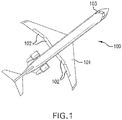
- Fig. 1 shows a top view of an aircraft 100 having an aircraft actuator system that employs the selector lever of the present disclosure.
- the selector lever of the aircraft actuator system may be used to control the position of a plurality of flaps 102 located on the wings 101 of the aircraft 100.
- the selector lever allows the operator (or pilot) to accurately control the position of the flaps 102 from the cockpit 103.
- Fig. 2A is a sectioned side view of a selector lever 1 according to one embodiment of the present disclosure.
- Fig. 2B is a sectioned side view of the selector lever 1 shown in Fig. 2A , from an opposing view.
- the selector lever 1 includes a shaft 2 having a proximal end 3 that is rotatably attached to a pivot 4 that is disposed in a housing 5.
- the shaft 2 also comprises a distal end 6 that extends from the housing 5.
- a slide 7 is arranged to move along the shaft 2, the slide 7 at least partially extending from the housing 5.
- Fig. 2A shows a first detent plate 8 with a first plurality of slots 9 disposed in the housing 5 parallel to the path of the pivoting shaft 2.
- Fig. 2B shows a second detent plate 10 with a second plurality of slots 11 disposed in the housing 5 parallel to the path of the pivoting shaft 2, opposite from the first detent plate 8.
- Fig. 2A shows a first detent pin 12 arranged on the shaft 2 to engage the first plurality of slots 9 of the first detent plate 8.
- the first detent pin 12 is operatively connected to the slide 7 such that translational movement of the slide 7 along the shaft results in movement of the first detent pin 12.
- Fig. 2B shows a second detent pin 13 arranged on the shaft 2 to engage the second plurality of slots 11 of the second detent plate 10, the second detent pin 13 being operatively connected to the slide 7.
- Fig. 2C shows a sectioned side view of the shaft 2 of the selector lever 1 shown in Figs. 2A and 2B .
- the slide 7 may be connected to a connecting member 14 disposed internal to the shaft 2.
- the first and second detent pins 12, 13, (second detent pin 13 not shown in Fig. 2C ), may be connected to the connecting member 14.
- the first and second detent pins 12, 13 may be directly connected to the slide 7.
- a biasing element 15, e.g., a spring
- one or more of the first plurality of slots 9 may be configured as a first failure detection slot 16.
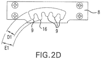
- Figs. 2D and 2E show the first and second detent plates 8, 10, respectively, in greater detail.
- the first failure detection slot 16 is characterized by a first extended radial depth E1 that is greater than a first radial depth D1 of the remaining of the first plurality of slots 9.
- one or more of the second plurality of slots 11 may be configured as a second failure detection slot 17, which is characterized by a second extended radial depth E2 that is greater than a second radial depth D2 of the remaining of the second plurality of slots 11.
- Figs. 2A and 2B also show the location of a failure indicator 18.
- the failure indicator 18 is positioned on the shaft 2 to be concealed by the slide 7 until the first or section detent pins 12, 13 enters the first or second extended radial depth E1, E2 of one of the respective first or second failure detection slots 16, 17 (see Figs. 5A and 5B ).
- the failure indicator 18 thereby provides a visual indication to the operator that one of the first or second detent pins 12, 13 has failed.
- the selector lever 1 may also comprise a normal indicator 19, positioned on the shaft 2 to be visible until the first or section detent pins 12, 13 enters the first or second extended radial depth E1, E2 of one of the respective first or second failure detection slots 16, 17.
- Figs. 3A and 3B illustrate the embodiment shown in Figs. 2A and 2B with the pins 12, 13 disengaged from the slot as described.
- the normal indicator 19 remains visible in this position while the failure indicator 18 remains concealed.
- the operator rotates the shaft 2 to the desired position.
- the operator moves the slide 7 along the shaft 2 in a direction allowing the first and second detent pins 12, 13 to engage the desired slot.
- Figs. 4A and 4B illustrate the selector lever 1 of Figs.
- Figs. 4A and 4B illustrate the selector lever 1 with at least the second detent pin 13 intact, wherein the first detent pin 12 enters the first failure detection slot 16, but does not enter the first extended radial depth E1. Accordingly, the failure indicator 18 remains concealed in Figs. 4A and 4B .
- Figs. 5A and 5B illustrate the selector lever 1 of Figs. 2A and 2B , with the shaft 2 in the position shown in Figs. 4A and 4B , where the second detent pin 13 has failed. Without the second detent pin 13 engaging the respective one of the second plurality of slots 11, the first detent pin 12 is biased by the biasing element 15, (see Fig. 2C ), into the first extended radial depth E1 of the first failure detection slot 16. This position moves the slide 7 further along the shaft 2, exposing the failure indicator 18 and concealing the normal indicator 19. In a similar manner, a failure of the first detent pin 12 would allow the second detent pin 13 to be biased into the second extended radial depth E2 by the biasing element 15, (see Fig.
- each of the first and second failure detection slots 16, 17 should be arranged opposing one of the remaining of the respective plurality of slots in the opposing detent plate.
- the present disclosure provides a visual indication of a detent pin failure during the normal operation of the selector lever 1.
- the failure indication may be provided at one or more positions of the selector lever 1.
- each incremental position of the selector lever 1, (for which a pair of corresponding slots has been provided, one in each detent plate), may include one first or second failure detection slot 16, 17.
- the present disclosure provides a positive indication confirming that at least one of the detent pins remains intact.
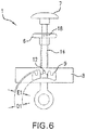
- Fig. 6 illustrates a sectioned side view of the selector lever 1 according to another example of the present disclosure, in which the direction moved by the first detent pin 12 to engage one of the first plurality of slots 9 is radially outward, i.e., away from the pivot 4.
- the slide 7 is moved in a radially inward direction to disengage the first detent pin 12 from the first detent plate 8.
- the failure indicator 18 is disposed on the connecting member 14, normally concealed by the distal end 6 of the shaft 2.
Landscapes
- Engineering & Computer Science (AREA)
- Automation & Control Theory (AREA)
- Aviation & Aerospace Engineering (AREA)
- Physics & Mathematics (AREA)
- General Physics & Mathematics (AREA)
- Mechanical Control Devices (AREA)
Abstract
Description
- The present disclosure relates generally to selector levers and, more particularly, to a failure detection mechanism for selector levers that may be found, for example, in the cockpit of an aircraft.
- Conventional aircraft are commonly equipped with a selector lever for manually controlling the actuation of flaps, ailerons, or other moveable features of the aircraft. The selector lever is mounted in the cockpit for the pilot to select the desired equipment configuration by moving the lever to a position corresponding to the desired equipment configuration. The conventional selector lever is typically constructed with a shaft rotatably arranged adjacent one or two detent plates. One or two detent pins corresponding to the detent plates are movably arranged on the shaft. This configuration provides a measure of redundancy that allows the selector lever to be functional after one detent pin has failed. The ability to detect the failure of one or both detent pins would reduce maintenance costs and improve aircraft safety. Accordingly, the industry is receptive to new developments that provide the capability to detect the failure of a detent pin.
- Disclosed herein is a selector lever that includes a shaft rotatably attached to a pivot. The pivot is disposed in a housing and the shaft extends from the housing. A slide is movably arranged on the shaft. First and second detent pins are operatively connected to the slide. A first detent plate is disposed in the housing having a first plurality of slots for receiving the first detent pin, each of the first plurality of slots having a first radial depth. At least one of the first plurality of slots is a first failure detection slot defined by a first extended radial depth that is greater than the first radial depth. A second detent plate is disposed in the housing having a second plurality of slots for receiving the second detent pin. At least one of the second plurality of slots is a second failure detection slot defined by a second extended radial depth that is greater than the second radial depth. A failure indicator is arranged to provide a visual indication when the either of the first or second detent pins enters the first or second extended radial depths, respectively.
- The following descriptions should not be considered limiting in any way. With reference to the accompanying drawings, like elements are numbered alike:
-
Fig. 1 is an illustration of an aircraft according to one embodiment; -
Figs. 2A and2B are opposing sectioned side views of a selector lever according to another embodiment; -
Fig. 2C is a sectioned side view of the selector lever shown inFigs. 2A and2B ; -
Figs. 2D and2E are side views of detent plates of the selector lever shown inFigs. 2A and2B ; -
Figs. 3A and3B are opposing sectioned side views of the selector lever shown inFigs. 2A and2B in another position; -
Figs. 4A and4B are opposing sectioned side views of the selector lever shown inFigs. 2A and2B in another position; -
Figs. 5A and5B are opposing sectioned side views of the selector lever shown inFigs. 2A and2B in another position; and -
Fig. 6 is a sectioned side view of a selector lever according to another embodiment. - A detailed description of one or more embodiments of the disclosed apparatus and method are presented herein by way of exemplification and not limitation with reference to the Figures. It is to be understood that other embodiments may be utilized and changes may be made without departing from the scope of the present disclosure. In particular, the disclosure provides various examples related to a selector lever for aircraft, whereas the advantages of the present disclosure as applied in a related field would be apparent to one having ordinary skill in the art and are considered to be within the scope of the present invention.
-
Fig. 1 shows a top view of anaircraft 100 having an aircraft actuator system that employs the selector lever of the present disclosure. For example, the selector lever of the aircraft actuator system may be used to control the position of a plurality offlaps 102 located on thewings 101 of theaircraft 100. The selector lever allows the operator (or pilot) to accurately control the position of theflaps 102 from thecockpit 103. -
Fig. 2A is a sectioned side view of a selector lever 1 according to one embodiment of the present disclosure.Fig. 2B is a sectioned side view of the selector lever 1 shown inFig. 2A , from an opposing view. The selector lever 1 includes ashaft 2 having aproximal end 3 that is rotatably attached to apivot 4 that is disposed in ahousing 5. Theshaft 2 also comprises adistal end 6 that extends from thehousing 5. Aslide 7 is arranged to move along theshaft 2, theslide 7 at least partially extending from thehousing 5. -
Fig. 2A shows a firstdetent plate 8 with a first plurality ofslots 9 disposed in thehousing 5 parallel to the path of thepivoting shaft 2.Fig. 2B shows a seconddetent plate 10 with a second plurality ofslots 11 disposed in thehousing 5 parallel to the path of thepivoting shaft 2, opposite from the firstdetent plate 8. -
Fig. 2A shows a firstdetent pin 12 arranged on theshaft 2 to engage the first plurality ofslots 9 of the firstdetent plate 8. The firstdetent pin 12 is operatively connected to theslide 7 such that translational movement of theslide 7 along the shaft results in movement of the firstdetent pin 12. Similarly,Fig. 2B shows a seconddetent pin 13 arranged on theshaft 2 to engage the second plurality ofslots 11 of the seconddetent plate 10, the seconddetent pin 13 being operatively connected to theslide 7. -
Fig. 2C shows a sectioned side view of theshaft 2 of the selector lever 1 shown inFigs. 2A and2B . As shown inFig. 2C , theslide 7 may be connected to a connectingmember 14 disposed internal to theshaft 2. The first and second detent pins 12, 13, (second detent pin 13 not shown inFig. 2C ), may be connected to the connectingmember 14. Alternatively, the first and second detent pins 12, 13 may be directly connected to theslide 7. A biasingelement 15, (e.g., a spring), may also be provided to bias the first and second detent pins 12, 13 into the respective slots. - As shown in
Fig. 2A , one or more of the first plurality ofslots 9 may be configured as a firstfailure detection slot 16.Figs. 2D and2E show the first andsecond detent plates Fig. 2D , the firstfailure detection slot 16 is characterized by a first extended radial depth E1 that is greater than a first radial depth D1 of the remaining of the first plurality ofslots 9. As further shown inFig. 2E , one or more of the second plurality ofslots 11 may be configured as a secondfailure detection slot 17, which is characterized by a second extended radial depth E2 that is greater than a second radial depth D2 of the remaining of the second plurality ofslots 11. The "remaining" of the first or second plurality ofslots respective detent pin shaft 2, i.e., the change in distance from thepivot 4. For example, where one of the slots is set at an angle such that the insertion of the respective detent pin would require the simultaneous rotation of theshaft 2, the radial depth measures only the radial aspect of such movement. Similarly, the "extended radial depth" denotes that the failure detection slot has a radial aspect that is greater than the nominal radial depth of the plurality of slots in the same detent plate. In this example, the first and second extended radial depths E1, E2 are radially inward from the first and second depths D 1, D2. -
Figs. 2A and2B also show the location of afailure indicator 18. Thefailure indicator 18 is positioned on theshaft 2 to be concealed by theslide 7 until the first or section detent pins 12, 13 enters the first or second extended radial depth E1, E2 of one of the respective first or secondfailure detection slots 16, 17 (seeFigs. 5A and5B ). As further discussed below, thefailure indicator 18 thereby provides a visual indication to the operator that one of the first or second detent pins 12, 13 has failed. The selector lever 1 may also comprise anormal indicator 19, positioned on theshaft 2 to be visible until the first or section detent pins 12, 13 enters the first or second extended radial depth E1, E2 of one of the respective first or secondfailure detection slots - In operation, the operator moves the selector lever 1 from one position to another by first moving the
slide 7 along theshaft 2 to disengage the first and second detent pins 12, 13 from the respective slot.Figs. 3A and3B illustrate the embodiment shown inFigs. 2A and2B with thepins normal indicator 19 remains visible in this position while thefailure indicator 18 remains concealed. Next, the operator rotates theshaft 2 to the desired position. Then, the operator moves theslide 7 along theshaft 2 in a direction allowing the first and second detent pins 12, 13 to engage the desired slot.Figs. 4A and4B illustrate the selector lever 1 ofFigs. 2A and2B , with theshaft 2 in the desired position with thefirst detent pin 12 engaging the firstfailure detection slot 16 and thesecond detent pin 13 engaging one of the remaining of the second plurality ofslots 11.Figs. 4A and4B illustrate the selector lever 1 with at least thesecond detent pin 13 intact, wherein thefirst detent pin 12 enters the firstfailure detection slot 16, but does not enter the first extended radial depth E1. Accordingly, thefailure indicator 18 remains concealed inFigs. 4A and4B . -
Figs. 5A and5B illustrate the selector lever 1 ofFigs. 2A and2B , with theshaft 2 in the position shown inFigs. 4A and4B , where thesecond detent pin 13 has failed. Without thesecond detent pin 13 engaging the respective one of the second plurality ofslots 11, thefirst detent pin 12 is biased by the biasingelement 15, (seeFig. 2C ), into the first extended radial depth E1 of the firstfailure detection slot 16. This position moves theslide 7 further along theshaft 2, exposing thefailure indicator 18 and concealing thenormal indicator 19. In a similar manner, a failure of thefirst detent pin 12 would allow thesecond detent pin 13 to be biased into the second extended radial depth E2 by the biasingelement 15, (seeFig. 2C ), when theshaft 2 is position to move thesecond detent pin 13 into the one or more second failure detection slot 17S. As may be apparent, each of the first and secondfailure detection slots - As described above, the present disclosure provides a visual indication of a detent pin failure during the normal operation of the selector lever 1. The failure indication may be provided at one or more positions of the selector lever 1. For example, each incremental position of the selector lever 1, (for which a pair of corresponding slots has been provided, one in each detent plate), may include one first or second
failure detection slot - As those in the art will ascertain, the features described above are merely exemplary and may be provided in many forms to achieve some or all of the advantages herein. For example,
Fig. 6 illustrates a sectioned side view of the selector lever 1 according to another example of the present disclosure, in which the direction moved by thefirst detent pin 12 to engage one of the first plurality ofslots 9 is radially outward, i.e., away from thepivot 4. In contrast with the embodiment ofFigs. 2A and2B , theslide 7 is moved in a radially inward direction to disengage thefirst detent pin 12 from thefirst detent plate 8. It follows that the first extended radial depth E1 is radially outward from the first radial depth D1 in this configuration. Also, in the embodiment shown inFig. 6 , thefailure indicator 18 is disposed on the connectingmember 14, normally concealed by thedistal end 6 of theshaft 2. - Other configurations are also possible without departing from the scope of the present disclosure. For example, the selector lever may be provided with markings on the housing to indicate which of the first and second detent pins has failed in the event of a failure indication.
- While the invention has been described with reference to an exemplary embodiment or embodiments, it will be understood by those skilled in the art that various changes may be made and equivalents may be substituted for elements thereof without departing from the scope of the invention. In addition, many modifications may be made to adapt a particular situation or material to the teachings of the invention without departing from the essential scope thereof. Also, in the drawings and the description, there have been disclosed exemplary embodiments of the invention and, although specific terms may have been employed, they are unless otherwise stated used in a generic and descriptive sense only and not for purposes of limitation, the scope of the invention therefore not being so limited. Moreover, the use of the terms first, second, etc. , do not denote any order or importance, but rather the terms first, second, etc. are used to distinguish one element from another. Furthermore, the use of the terms a, an, etc. do not denote a limitation of quantity, but rather denote the presence of at least one of the referenced item.
Claims (6)
- A selector lever (1), comprising:a shaft (2) having a proximal end (3) rotatably attached to a pivot (4), the pivot (4) being disposed within a housing (5), the shaft (2) having a distal end (6) extending from the housing (5);a slide (7) arranged to be movable along the shaft (2);a first detent pin (12) operatively connected to the slide (7);a second detent pin (13) operatively connected to the slide (7);a first detent plate (8) disposed in the housing (5) and having a first plurality of slots (9) for receiving the first detent pin (12), each of the first plurality of slots (9) having a first radial depth (D1), at least one of the first plurality of slots (9) comprising a first failure detection slot (16), the first failure detection slot (16) defined by a first extended radial depth (E1) that is greater than the first radial depth (D1);a second detent plate (10) disposed in the housing (5) and having a second plurality of slots (11) for receiving the second detent pin (13), each of the second plurality of slots (11) having a second radial depth (D2), at least one of the second plurality of slots (11) comprising a second failure detection slot (17), the second failure detection slot (17) defined by a second extended radial depth (E2) that is greater than the second radial depth (D2), wherein the first failure detection slot (16) and the second failure detection slot (17) are not arranged opposite one another; anda failure indicator (18) arranged to provide a visual indication when the first detent pin (12) enters the first extended radial depth (E1) or when the second detent pin (13) enters the second extended radial depth (E2).
- The selector lever (1) of claim 1, wherein the failure indicator (18) is arranged on the shaft.
- The selector lever (1) of claim 2, the failure indicator (18) being normally concealed by the slide (7).
- The selector lever (1) of any preceding claim, further comprising a normal indicator (19) that is visible until one of the first or second detent pins (12, 13) runs into the extended radial depth (E1, E2) of one of the first or second failure detection slots (16, 17).
- The selector lever (1) of any preceding claim, further comprising a biasing element (15) for biasing the slide (7) towards the pivot (4).
- The selector lever (1) of any preceding claim, the selector lever (5) forming part of an aircraft actuator system.
Applications Claiming Priority (2)
| Application Number | Priority Date | Filing Date | Title |
|---|---|---|---|
| US14/495,030 US10031546B2 (en) | 2014-09-24 | 2014-09-24 | Visual failure indication for selector lever |
| EP15186648.0A EP3000727B1 (en) | 2014-09-24 | 2015-09-24 | Visual failure indication for selector lever |
Related Parent Applications (2)
| Application Number | Title | Priority Date | Filing Date |
|---|---|---|---|
| EP15186648.0A Division EP3000727B1 (en) | 2014-09-24 | 2015-09-24 | Visual failure indication for selector lever |
| EP15186648.0A Division-Into EP3000727B1 (en) | 2014-09-24 | 2015-09-24 | Visual failure indication for selector lever |
Publications (2)
| Publication Number | Publication Date |
|---|---|
| EP3153405A1 true EP3153405A1 (en) | 2017-04-12 |
| EP3153405B1 EP3153405B1 (en) | 2019-01-02 |
Family
ID=54199585
Family Applications (2)
| Application Number | Title | Priority Date | Filing Date |
|---|---|---|---|
| EP16197586.7A Active EP3153405B1 (en) | 2014-09-24 | 2015-09-24 | Visual failure indication for selector level |
| EP15186648.0A Active EP3000727B1 (en) | 2014-09-24 | 2015-09-24 | Visual failure indication for selector lever |
Family Applications After (1)
| Application Number | Title | Priority Date | Filing Date |
|---|---|---|---|
| EP15186648.0A Active EP3000727B1 (en) | 2014-09-24 | 2015-09-24 | Visual failure indication for selector lever |
Country Status (2)
| Country | Link |
|---|---|
| US (1) | US10031546B2 (en) |
| EP (2) | EP3153405B1 (en) |
Families Citing this family (6)
| Publication number | Priority date | Publication date | Assignee | Title |
|---|---|---|---|---|
| US10351257B2 (en) * | 2017-09-28 | 2019-07-16 | Hamilton Sundstrand Corporation | Retention member monitoring system for slat-flap control lever |
| US11299256B2 (en) * | 2019-05-15 | 2022-04-12 | Textron Innovations, Inc. | Flap lever |
| DE102020114634B4 (en) * | 2019-07-18 | 2023-07-20 | Defond Components Limited | Control assembly for use with an electrical device and a corresponding electrical device |
| JP7533228B2 (en) | 2021-01-07 | 2024-08-14 | スズキ株式会社 | Marine propulsion device operating device |
| CN113772080A (en) * | 2021-09-30 | 2021-12-10 | 兰州万里航空机电有限责任公司 | A dual-margin flap control switch that can be operated with one hand |
| US12600491B2 (en) * | 2023-02-15 | 2026-04-14 | Hamilton Sundstrand Corporation | Push button motion indicator mechanism |
Citations (5)
| Publication number | Priority date | Publication date | Assignee | Title |
|---|---|---|---|---|
| US1987066A (en) * | 1933-01-30 | 1935-01-08 | Gen Aviat Mfg Corp | Vernier adjusting control unit |
| US4126054A (en) * | 1976-03-08 | 1978-11-21 | Incom International Inc. | Control means |
| US5085096A (en) * | 1989-12-11 | 1992-02-04 | Chrysler Corporation | Gearshift park interlock system |
| US20140116194A1 (en) * | 2012-10-25 | 2014-05-01 | Cessna Aircraft Company | Self-centering aircraft flap position command apparatus |
| WO2014084809A1 (en) * | 2012-11-27 | 2014-06-05 | Bombardier Inc. | Failure detection mechanism for selector lever |
Family Cites Families (5)
| Publication number | Priority date | Publication date | Assignee | Title |
|---|---|---|---|---|
| US4012015A (en) | 1975-12-29 | 1977-03-15 | Northrop Corporation | Control and synchronization of twin engines with a master throttle lever |
| ES2102967B1 (en) * | 1995-04-26 | 1998-04-01 | Fico Triad Sa | SIGNALING DEVICE FOR THE POSITION OF THE LEVER ARM FOR AUTOMATIC SPEED CHANGES. |
| US6168181B1 (en) * | 1997-12-03 | 2001-01-02 | Ben R. Gadd | Trailer alignment backing aid for vehicles |
| US6244207B1 (en) * | 1999-06-02 | 2001-06-12 | Chieh-Yuan Chen | Bicycle gear shift indicating device |
| US8528441B2 (en) * | 2011-01-14 | 2013-09-10 | Avibank Manufacturing, Inc. | Handle for latching mechanism |
-
2014
- 2014-09-24 US US14/495,030 patent/US10031546B2/en active Active
-
2015
- 2015-09-24 EP EP16197586.7A patent/EP3153405B1/en active Active
- 2015-09-24 EP EP15186648.0A patent/EP3000727B1/en active Active
Patent Citations (5)
| Publication number | Priority date | Publication date | Assignee | Title |
|---|---|---|---|---|
| US1987066A (en) * | 1933-01-30 | 1935-01-08 | Gen Aviat Mfg Corp | Vernier adjusting control unit |
| US4126054A (en) * | 1976-03-08 | 1978-11-21 | Incom International Inc. | Control means |
| US5085096A (en) * | 1989-12-11 | 1992-02-04 | Chrysler Corporation | Gearshift park interlock system |
| US20140116194A1 (en) * | 2012-10-25 | 2014-05-01 | Cessna Aircraft Company | Self-centering aircraft flap position command apparatus |
| WO2014084809A1 (en) * | 2012-11-27 | 2014-06-05 | Bombardier Inc. | Failure detection mechanism for selector lever |
Also Published As
| Publication number | Publication date |
|---|---|
| US20160085259A1 (en) | 2016-03-24 |
| EP3000727B1 (en) | 2017-08-09 |
| EP3000727A1 (en) | 2016-03-30 |
| EP3153405B1 (en) | 2019-01-02 |
| US10031546B2 (en) | 2018-07-24 |
Similar Documents
| Publication | Publication Date | Title |
|---|---|---|
| EP3153405B1 (en) | Visual failure indication for selector level | |
| EP2925603B1 (en) | Failure detection mechanism for selector lever | |
| RU2760777C2 (en) | Testing tool for the control apparatus of the steering drive of a plane | |
| CA2919342C (en) | Check device for flight actuator primary load path failure detection device | |
| EP3000725B1 (en) | Selector lever with failure detection features | |
| EP3012191B1 (en) | Method for determining a state of a component in a high lift system of an aircraft, high lift system of an aircraft and aircraft having such a high lift system | |
| EP3000726A1 (en) | Device for preventing rotational movement of failed selector lever | |
| US10472045B2 (en) | System for locking a foldable wing tip on a wing end of an aircraft | |
| US20060145028A1 (en) | Device for monitoring tiltable flaps on aircraft wings | |
| US11035445B2 (en) | Horizontal stabiliser actuator with freeplay detecting features and method thereof | |
| EP2947004B1 (en) | Method for determining the position of a component in a high lift system of an aircraft, high lift system of an aircraft and aircraft | |
| EP3006330B1 (en) | Selector lever with independent slides | |
| EP3081481B1 (en) | Check device for a flight actuator primary load path failure detection device | |
| EP3012192B1 (en) | Method for determining a state of a component in a high lift system of an aircraft, high lift system of an aircraft and aircraft having such a high lift system | |
| EP3461739B1 (en) | Retention member monitoring system for slat-flap control lever | |
| EP4282766B1 (en) | High lift skew system |
Legal Events
| Date | Code | Title | Description |
|---|---|---|---|
| PUAI | Public reference made under article 153(3) epc to a published international application that has entered the european phase |
Free format text: ORIGINAL CODE: 0009012 |
|
| STAA | Information on the status of an ep patent application or granted ep patent |
Free format text: STATUS: THE APPLICATION HAS BEEN PUBLISHED |
|
| AC | Divisional application: reference to earlier application |
Ref document number: 3000727 Country of ref document: EP Kind code of ref document: P |
|
| AK | Designated contracting states |
Kind code of ref document: A1 Designated state(s): AL AT BE BG CH CY CZ DE DK EE ES FI FR GB GR HR HU IE IS IT LI LT LU LV MC MK MT NL NO PL PT RO RS SE SI SK SM TR |
|
| AX | Request for extension of the european patent |
Extension state: BA ME |
|
| STAA | Information on the status of an ep patent application or granted ep patent |
Free format text: STATUS: REQUEST FOR EXAMINATION WAS MADE |
|
| 17P | Request for examination filed |
Effective date: 20170929 |
|
| RBV | Designated contracting states (corrected) |
Designated state(s): AL AT BE BG CH CY CZ DE DK EE ES FI FR GB GR HR HU IE IS IT LI LT LU LV MC MK MT NL NO PL PT RO RS SE SI SK SM TR |
|
| RIC1 | Information provided on ipc code assigned before grant |
Ipc: G05G 25/00 20060101ALN20180518BHEP Ipc: G05G 5/06 20060101ALI20180518BHEP Ipc: G05G 1/04 20060101ALI20180518BHEP Ipc: G05G 1/06 20060101ALI20180518BHEP Ipc: B64D 45/00 20060101ALI20180518BHEP Ipc: B64C 13/14 20060101AFI20180518BHEP |
|
| GRAP | Despatch of communication of intention to grant a patent |
Free format text: ORIGINAL CODE: EPIDOSNIGR1 |
|
| STAA | Information on the status of an ep patent application or granted ep patent |
Free format text: STATUS: GRANT OF PATENT IS INTENDED |
|
| INTG | Intention to grant announced |
Effective date: 20180718 |
|
| GRAS | Grant fee paid |
Free format text: ORIGINAL CODE: EPIDOSNIGR3 |
|
| GRAA | (expected) grant |
Free format text: ORIGINAL CODE: 0009210 |
|
| STAA | Information on the status of an ep patent application or granted ep patent |
Free format text: STATUS: THE PATENT HAS BEEN GRANTED |
|
| AC | Divisional application: reference to earlier application |
Ref document number: 3000727 Country of ref document: EP Kind code of ref document: P |
|
| AK | Designated contracting states |
Kind code of ref document: B1 Designated state(s): AL AT BE BG CH CY CZ DE DK EE ES FI FR GB GR HR HU IE IS IT LI LT LU LV MC MK MT NL NO PL PT RO RS SE SI SK SM TR |
|
| REG | Reference to a national code |
Ref country code: GB Ref legal event code: FG4D |
|
| REG | Reference to a national code |
Ref country code: CH Ref legal event code: EP Ref country code: AT Ref legal event code: REF Ref document number: 1084024 Country of ref document: AT Kind code of ref document: T Effective date: 20190115 |
|
| REG | Reference to a national code |
Ref country code: IE Ref legal event code: FG4D |
|
| REG | Reference to a national code |
Ref country code: DE Ref legal event code: R096 Ref document number: 602015023027 Country of ref document: DE |
|
| REG | Reference to a national code |
Ref country code: NL Ref legal event code: MP Effective date: 20190102 |
|
| REG | Reference to a national code |
Ref country code: LT Ref legal event code: MG4D |
|
| REG | Reference to a national code |
Ref country code: AT Ref legal event code: MK05 Ref document number: 1084024 Country of ref document: AT Kind code of ref document: T Effective date: 20190102 |
|
| PG25 | Lapsed in a contracting state [announced via postgrant information from national office to epo] |
Ref country code: NL Free format text: LAPSE BECAUSE OF FAILURE TO SUBMIT A TRANSLATION OF THE DESCRIPTION OR TO PAY THE FEE WITHIN THE PRESCRIBED TIME-LIMIT Effective date: 20190102 |
|
| PG25 | Lapsed in a contracting state [announced via postgrant information from national office to epo] |
Ref country code: PT Free format text: LAPSE BECAUSE OF FAILURE TO SUBMIT A TRANSLATION OF THE DESCRIPTION OR TO PAY THE FEE WITHIN THE PRESCRIBED TIME-LIMIT Effective date: 20190502 Ref country code: ES Free format text: LAPSE BECAUSE OF FAILURE TO SUBMIT A TRANSLATION OF THE DESCRIPTION OR TO PAY THE FEE WITHIN THE PRESCRIBED TIME-LIMIT Effective date: 20190102 Ref country code: NO Free format text: LAPSE BECAUSE OF FAILURE TO SUBMIT A TRANSLATION OF THE DESCRIPTION OR TO PAY THE FEE WITHIN THE PRESCRIBED TIME-LIMIT Effective date: 20190402 Ref country code: FI Free format text: LAPSE BECAUSE OF FAILURE TO SUBMIT A TRANSLATION OF THE DESCRIPTION OR TO PAY THE FEE WITHIN THE PRESCRIBED TIME-LIMIT Effective date: 20190102 Ref country code: LT Free format text: LAPSE BECAUSE OF FAILURE TO SUBMIT A TRANSLATION OF THE DESCRIPTION OR TO PAY THE FEE WITHIN THE PRESCRIBED TIME-LIMIT Effective date: 20190102 Ref country code: SE Free format text: LAPSE BECAUSE OF FAILURE TO SUBMIT A TRANSLATION OF THE DESCRIPTION OR TO PAY THE FEE WITHIN THE PRESCRIBED TIME-LIMIT Effective date: 20190102 Ref country code: PL Free format text: LAPSE BECAUSE OF FAILURE TO SUBMIT A TRANSLATION OF THE DESCRIPTION OR TO PAY THE FEE WITHIN THE PRESCRIBED TIME-LIMIT Effective date: 20190102 |
|
| PG25 | Lapsed in a contracting state [announced via postgrant information from national office to epo] |
Ref country code: BG Free format text: LAPSE BECAUSE OF FAILURE TO SUBMIT A TRANSLATION OF THE DESCRIPTION OR TO PAY THE FEE WITHIN THE PRESCRIBED TIME-LIMIT Effective date: 20190402 Ref country code: GR Free format text: LAPSE BECAUSE OF FAILURE TO SUBMIT A TRANSLATION OF THE DESCRIPTION OR TO PAY THE FEE WITHIN THE PRESCRIBED TIME-LIMIT Effective date: 20190403 Ref country code: HR Free format text: LAPSE BECAUSE OF FAILURE TO SUBMIT A TRANSLATION OF THE DESCRIPTION OR TO PAY THE FEE WITHIN THE PRESCRIBED TIME-LIMIT Effective date: 20190102 Ref country code: IS Free format text: LAPSE BECAUSE OF FAILURE TO SUBMIT A TRANSLATION OF THE DESCRIPTION OR TO PAY THE FEE WITHIN THE PRESCRIBED TIME-LIMIT Effective date: 20190502 Ref country code: LV Free format text: LAPSE BECAUSE OF FAILURE TO SUBMIT A TRANSLATION OF THE DESCRIPTION OR TO PAY THE FEE WITHIN THE PRESCRIBED TIME-LIMIT Effective date: 20190102 Ref country code: RS Free format text: LAPSE BECAUSE OF FAILURE TO SUBMIT A TRANSLATION OF THE DESCRIPTION OR TO PAY THE FEE WITHIN THE PRESCRIBED TIME-LIMIT Effective date: 20190102 |
|
| REG | Reference to a national code |
Ref country code: DE Ref legal event code: R097 Ref document number: 602015023027 Country of ref document: DE |
|
| PG25 | Lapsed in a contracting state [announced via postgrant information from national office to epo] |
Ref country code: IT Free format text: LAPSE BECAUSE OF FAILURE TO SUBMIT A TRANSLATION OF THE DESCRIPTION OR TO PAY THE FEE WITHIN THE PRESCRIBED TIME-LIMIT Effective date: 20190102 Ref country code: RO Free format text: LAPSE BECAUSE OF FAILURE TO SUBMIT A TRANSLATION OF THE DESCRIPTION OR TO PAY THE FEE WITHIN THE PRESCRIBED TIME-LIMIT Effective date: 20190102 Ref country code: CZ Free format text: LAPSE BECAUSE OF FAILURE TO SUBMIT A TRANSLATION OF THE DESCRIPTION OR TO PAY THE FEE WITHIN THE PRESCRIBED TIME-LIMIT Effective date: 20190102 Ref country code: SK Free format text: LAPSE BECAUSE OF FAILURE TO SUBMIT A TRANSLATION OF THE DESCRIPTION OR TO PAY THE FEE WITHIN THE PRESCRIBED TIME-LIMIT Effective date: 20190102 Ref country code: AT Free format text: LAPSE BECAUSE OF FAILURE TO SUBMIT A TRANSLATION OF THE DESCRIPTION OR TO PAY THE FEE WITHIN THE PRESCRIBED TIME-LIMIT Effective date: 20190102 Ref country code: EE Free format text: LAPSE BECAUSE OF FAILURE TO SUBMIT A TRANSLATION OF THE DESCRIPTION OR TO PAY THE FEE WITHIN THE PRESCRIBED TIME-LIMIT Effective date: 20190102 Ref country code: AL Free format text: LAPSE BECAUSE OF FAILURE TO SUBMIT A TRANSLATION OF THE DESCRIPTION OR TO PAY THE FEE WITHIN THE PRESCRIBED TIME-LIMIT Effective date: 20190102 Ref country code: DK Free format text: LAPSE BECAUSE OF FAILURE TO SUBMIT A TRANSLATION OF THE DESCRIPTION OR TO PAY THE FEE WITHIN THE PRESCRIBED TIME-LIMIT Effective date: 20190102 |
|
| PLBE | No opposition filed within time limit |
Free format text: ORIGINAL CODE: 0009261 |
|
| STAA | Information on the status of an ep patent application or granted ep patent |
Free format text: STATUS: NO OPPOSITION FILED WITHIN TIME LIMIT |
|
| PG25 | Lapsed in a contracting state [announced via postgrant information from national office to epo] |
Ref country code: SM Free format text: LAPSE BECAUSE OF FAILURE TO SUBMIT A TRANSLATION OF THE DESCRIPTION OR TO PAY THE FEE WITHIN THE PRESCRIBED TIME-LIMIT Effective date: 20190102 |
|
| 26N | No opposition filed |
Effective date: 20191003 |
|
| PG25 | Lapsed in a contracting state [announced via postgrant information from national office to epo] |
Ref country code: SI Free format text: LAPSE BECAUSE OF FAILURE TO SUBMIT A TRANSLATION OF THE DESCRIPTION OR TO PAY THE FEE WITHIN THE PRESCRIBED TIME-LIMIT Effective date: 20190102 |
|
| PG25 | Lapsed in a contracting state [announced via postgrant information from national office to epo] |
Ref country code: TR Free format text: LAPSE BECAUSE OF FAILURE TO SUBMIT A TRANSLATION OF THE DESCRIPTION OR TO PAY THE FEE WITHIN THE PRESCRIBED TIME-LIMIT Effective date: 20190102 |
|
| REG | Reference to a national code |
Ref country code: DE Ref legal event code: R119 Ref document number: 602015023027 Country of ref document: DE |
|
| PG25 | Lapsed in a contracting state [announced via postgrant information from national office to epo] |
Ref country code: MC Free format text: LAPSE BECAUSE OF FAILURE TO SUBMIT A TRANSLATION OF THE DESCRIPTION OR TO PAY THE FEE WITHIN THE PRESCRIBED TIME-LIMIT Effective date: 20190102 |
|
| REG | Reference to a national code |
Ref country code: CH Ref legal event code: PL |
|
| PG25 | Lapsed in a contracting state [announced via postgrant information from national office to epo] |
Ref country code: DE Free format text: LAPSE BECAUSE OF NON-PAYMENT OF DUE FEES Effective date: 20200401 Ref country code: CH Free format text: LAPSE BECAUSE OF NON-PAYMENT OF DUE FEES Effective date: 20190930 Ref country code: LI Free format text: LAPSE BECAUSE OF NON-PAYMENT OF DUE FEES Effective date: 20190930 Ref country code: LU Free format text: LAPSE BECAUSE OF NON-PAYMENT OF DUE FEES Effective date: 20190924 Ref country code: IE Free format text: LAPSE BECAUSE OF NON-PAYMENT OF DUE FEES Effective date: 20190924 |
|
| REG | Reference to a national code |
Ref country code: BE Ref legal event code: MM Effective date: 20190930 |
|
| PG25 | Lapsed in a contracting state [announced via postgrant information from national office to epo] |
Ref country code: BE Free format text: LAPSE BECAUSE OF NON-PAYMENT OF DUE FEES Effective date: 20190930 |
|
| PG25 | Lapsed in a contracting state [announced via postgrant information from national office to epo] |
Ref country code: CY Free format text: LAPSE BECAUSE OF FAILURE TO SUBMIT A TRANSLATION OF THE DESCRIPTION OR TO PAY THE FEE WITHIN THE PRESCRIBED TIME-LIMIT Effective date: 20190102 |
|
| PG25 | Lapsed in a contracting state [announced via postgrant information from national office to epo] |
Ref country code: MT Free format text: LAPSE BECAUSE OF FAILURE TO SUBMIT A TRANSLATION OF THE DESCRIPTION OR TO PAY THE FEE WITHIN THE PRESCRIBED TIME-LIMIT Effective date: 20190102 Ref country code: HU Free format text: LAPSE BECAUSE OF FAILURE TO SUBMIT A TRANSLATION OF THE DESCRIPTION OR TO PAY THE FEE WITHIN THE PRESCRIBED TIME-LIMIT; INVALID AB INITIO Effective date: 20150924 |
|
| PG25 | Lapsed in a contracting state [announced via postgrant information from national office to epo] |
Ref country code: MK Free format text: LAPSE BECAUSE OF FAILURE TO SUBMIT A TRANSLATION OF THE DESCRIPTION OR TO PAY THE FEE WITHIN THE PRESCRIBED TIME-LIMIT Effective date: 20190102 |
|
| P01 | Opt-out of the competence of the unified patent court (upc) registered |
Effective date: 20230522 |
|
| PGFP | Annual fee paid to national office [announced via postgrant information from national office to epo] |
Ref country code: GB Payment date: 20250919 Year of fee payment: 11 |
|
| PGFP | Annual fee paid to national office [announced via postgrant information from national office to epo] |
Ref country code: FR Payment date: 20250929 Year of fee payment: 11 |