EP3153255B1 - Gehäuse für ein getriebe und verwendung eines additiven fertigungsverfahrens - Google Patents
Gehäuse für ein getriebe und verwendung eines additiven fertigungsverfahrens Download PDFInfo
- Publication number
- EP3153255B1 EP3153255B1 EP16002130.9A EP16002130A EP3153255B1 EP 3153255 B1 EP3153255 B1 EP 3153255B1 EP 16002130 A EP16002130 A EP 16002130A EP 3153255 B1 EP3153255 B1 EP 3153255B1
- Authority
- EP
- European Patent Office
- Prior art keywords
- housing
- additive manufacturing
- transmission
- steel
- produced
- Prior art date
- Legal status (The legal status is an assumption and is not a legal conclusion. Google has not performed a legal analysis and makes no representation as to the accuracy of the status listed.)
- Active
Links
Images
Classifications
-
- B—PERFORMING OPERATIONS; TRANSPORTING
- B22—CASTING; POWDER METALLURGY
- B22F—WORKING METALLIC POWDER; MANUFACTURE OF ARTICLES FROM METALLIC POWDER; MAKING METALLIC POWDER; APPARATUS OR DEVICES SPECIALLY ADAPTED FOR METALLIC POWDER
- B22F5/00—Manufacture of workpieces or articles from metallic powder characterised by the special shape of the product
- B22F5/10—Manufacture of workpieces or articles from metallic powder characterised by the special shape of the product of articles with cavities or holes, not otherwise provided for in the preceding subgroups
-
- B—PERFORMING OPERATIONS; TRANSPORTING
- B22—CASTING; POWDER METALLURGY
- B22F—WORKING METALLIC POWDER; MANUFACTURE OF ARTICLES FROM METALLIC POWDER; MAKING METALLIC POWDER; APPARATUS OR DEVICES SPECIALLY ADAPTED FOR METALLIC POWDER
- B22F10/00—Additive manufacturing of workpieces or articles from metallic powder
- B22F10/20—Direct sintering or melting
- B22F10/28—Powder bed fusion, e.g. selective laser melting [SLM] or electron beam melting [EBM]
-
- B—PERFORMING OPERATIONS; TRANSPORTING
- B22—CASTING; POWDER METALLURGY
- B22F—WORKING METALLIC POWDER; MANUFACTURE OF ARTICLES FROM METALLIC POWDER; MAKING METALLIC POWDER; APPARATUS OR DEVICES SPECIALLY ADAPTED FOR METALLIC POWDER
- B22F10/00—Additive manufacturing of workpieces or articles from metallic powder
- B22F10/80—Data acquisition or data processing
-
- B—PERFORMING OPERATIONS; TRANSPORTING
- B33—ADDITIVE MANUFACTURING TECHNOLOGY
- B33Y—ADDITIVE MANUFACTURING, i.e. MANUFACTURING OF THREE-DIMENSIONAL [3D] OBJECTS BY ADDITIVE DEPOSITION, ADDITIVE AGGLOMERATION OR ADDITIVE LAYERING, e.g. BY 3D PRINTING, STEREOLITHOGRAPHY OR SELECTIVE LASER SINTERING
- B33Y80/00—Products made by additive manufacturing
-
- F—MECHANICAL ENGINEERING; LIGHTING; HEATING; WEAPONS; BLASTING
- F16—ENGINEERING ELEMENTS AND UNITS; GENERAL MEASURES FOR PRODUCING AND MAINTAINING EFFECTIVE FUNCTIONING OF MACHINES OR INSTALLATIONS; THERMAL INSULATION IN GENERAL
- F16H—GEARING
- F16H57/00—General details of gearing
- F16H57/02—Gearboxes; Mounting gearing therein
- F16H57/032—Gearboxes; Mounting gearing therein characterised by the materials used
-
- B—PERFORMING OPERATIONS; TRANSPORTING
- B22—CASTING; POWDER METALLURGY
- B22F—WORKING METALLIC POWDER; MANUFACTURE OF ARTICLES FROM METALLIC POWDER; MAKING METALLIC POWDER; APPARATUS OR DEVICES SPECIALLY ADAPTED FOR METALLIC POWDER
- B22F7/00—Manufacture of composite layers, workpieces, or articles, comprising metallic powder, by sintering the powder, with or without compacting wherein at least one part is obtained by sintering or compression
- B22F7/06—Manufacture of composite layers, workpieces, or articles, comprising metallic powder, by sintering the powder, with or without compacting wherein at least one part is obtained by sintering or compression of composite workpieces or articles from parts, e.g. to form tipped tools
- B22F7/062—Manufacture of composite layers, workpieces, or articles, comprising metallic powder, by sintering the powder, with or without compacting wherein at least one part is obtained by sintering or compression of composite workpieces or articles from parts, e.g. to form tipped tools involving the connection or repairing of preformed parts
-
- Y—GENERAL TAGGING OF NEW TECHNOLOGICAL DEVELOPMENTS; GENERAL TAGGING OF CROSS-SECTIONAL TECHNOLOGIES SPANNING OVER SEVERAL SECTIONS OF THE IPC; TECHNICAL SUBJECTS COVERED BY FORMER USPC CROSS-REFERENCE ART COLLECTIONS [XRACs] AND DIGESTS
- Y02—TECHNOLOGIES OR APPLICATIONS FOR MITIGATION OR ADAPTATION AGAINST CLIMATE CHANGE
- Y02P—CLIMATE CHANGE MITIGATION TECHNOLOGIES IN THE PRODUCTION OR PROCESSING OF GOODS
- Y02P10/00—Technologies related to metal processing
- Y02P10/25—Process efficiency
Definitions
- the invention relates to a housing for a transmission.
- the housing serves to receive the transmission, in particular of gears and shafts.
- the invention relates to a housing with a gear received therein.
- the FR 3 016 407 A1 describes an accessory gearbox for a turbojet engine having two arms in which transmission lines are mounted.
- the housing of the accessory gearbox can be manufactured by additive manufacturing such as laser beam melting.
- the GB 2 521 391 A deals with components, which may be part of a bearing, an actuator, a gear, a gear housing, etc.
- a label is embedded in order to distinguish these from counterfeits can.
- the WO 2016/111896 A1 deals with an at least partially produced with an additive manufacturing process structure in which a vibration damper is embedded. It is proposed to use the structure for parts of a helicopter, such as gears, housings, etc.
- the object of the invention is to provide an improved housing.
- the housing is a housing for a transmission.
- the housing serves to receive the transmission or picks up the transmission.
- At least a portion of the housing is manufactured using an additive manufacturing process.
- a portion which at least partially adjoins the transmission or a part of the transmission is produced by means of an additive manufacturing process.
- additive manufacturing process for manufacturing processes, for which a variety of names are common in the literature. Such manufacturing processes are also called, for example, “additive manufacturing processes”, “additive manufacturing”, “rapid prototyping”, “rapid manufacturing” or “3D printing”.
- additive manufacturing processes for example, “additive manufacturing processes”, “additive manufacturing”, “rapid prototyping”, “rapid manufacturing” or “3D printing”.
- additive manufacturing processes can be found, for example, in the document “ 'VDI Status Report Additive Manufacturing September 2014', Association of German Engineers eV, Dr. Ing. Erik Marquardt, Department of Production Engineering and Manufacturing, PDF file for free download at www.vdi.de/statusadditiv ".
- the housing material For the selection of the housing material, a number of materials are available, which can be processed with additive manufacturing processes. So can In particular, a material can be selected which is favorable in terms of its thermal expansion for the transmission to be used to reduce or avoid binding, increased friction or even jamming or unfavorable tolerance levels over the entire specified temperature range.
- the housing is a housing of a steering machine for a tail of an aircraft.
- the steering machine contains the gearbox.
- the aircraft is in particular an aircraft, a missile or a missile. In such cases, the above advantages, e.g. Lightweight construction, particularly advantageous because of the achievable weight savings.
- the invention is based on the following considerations and findings: From practice, lightweight gearboxes, in particular rowing machines, are known, which usually have a housing made of aluminum.
- the actual transmission or the actual transmission elements, such as gears and shafts, are usually heavily loaded and made of steel. At temperature gear it comes because of the different dimensions to jamming in the transmission.
- Reason for the increased friction moments in the known housing or the known gear or rowing machine are the different material pairings of housing and gearbox.
- the gearbox is usually made of steel to interpret the gear or the gears for the high loads occurring.
- a common temperature range for the housing specification for rowing machines is, for example, -55 ° C to + 80 ° C.
- Those housing parts that are not made of steel but eg made of aluminum, have other thermal expansions. This leads in the usual temperature range for the housing specification to increased friction or jamming. It is desirable to keep the friction moments over a wide temperature range, in particular the above-mentioned specification range, largely constant.
- a first conceivable solution would be the installation of a heater in order to avoid the disadvantages at low temperatures, that the transmission, in particular the steering machine is stabilized at uncritical temperatures. Furthermore, a possible solution would be to build the housing or the transmission of materials of at least similar thermal expansion. One possibility would be, for example, to manufacture the housing of an expensive titanium alloy, but this would mean a cost disadvantage.
- the steel housing then has the same thermal expansion as a steel gear or its gears, whereby different material expansions are prevented.
- the housing can be made lightweight. It may be a summary of common aluminum and steel housing components to a monolithic steel housing.
- a multi-part gear or rowing machine housing, which was previously made of mixed materials, can now be designed as a one-piece housing, at the same time the risk of thermal stresses is banned. In other words, the housing is thus constructed using methods of additive manufacturing.
- gearbox or steering machine housings made of steel of the same weight and stiffness as previous housings made of aluminum or aluminum can be produced. According to this variant of the invention, therefore, a temperature-stress-free lightweight housing can be realized.
- An aluminum or hybrid housing which has hitherto been customary, can be realized due to the novel additive manufacturing technology by a steel housing of equal weight and stiffness. All creative degrees of freedom of additive manufacturing processes, for example, in particular the SLM process (selective laser melting), also called LBM (laser beam melting), can be used.
- SLM process selective laser melting
- LBM laser beam melting
- the housing is made in one piece.
- the one-piece housing can be completely manufactured by means of an additive manufacturing process. But it is also possible to use additive manufacturing process only certain sections of the housing, in particular those sections which are at least partially adjacent to the gearbox to manufacture and produce the remaining sections conventionally. Finally, all sections of the housing are then integrally connected, for example, welded.
- At least a portion of that portion of the housing made using the additive manufacturing process has a microstructure.
- the microstructure - eg as weight-saving structure mentioned above - contains a plurality of connecting webs with intermediate spaces.
- the corresponding housing section is designed in particular as a micromachine, as for example from the DE 10 2014 003 441 A1 is known.
- Such a microstructure in spite of its free space, is sufficiently stable compared to a casing section made of solid material, but it is weight-saving. In particular, such microstructures are difficult or impossible to produce using conventional production methods, but can be produced without difficulty by the additive manufacturing method.
- the additive manufacturing process is an SLM or LBM process.
- the housing is constructed bionically or according to a bionic approach.
- a correspondingly bionic approach generally creates filigree or organically appearing structures, which can be embodied in particular as a microfachament, as explained above, and have a large number of cavities between connecting webs.
- the bionic approach mimics or imitates, in particular, naturally occurring structures which, for example, can be particularly stable and at the same time particularly light.
- the object of the invention is also achieved by the use of an additive manufacturing method according to claim 10.
- the additive manufacturing process is used in this case for producing the abovementioned housing according to the invention.
- the use and its preferred embodiments and their advantages have been explained analogously already in connection with the housing according to the invention.
- the problem of the housing 2 as a hybrid component H, ie in hybrid construction, here consists in the different thermal expansion of the housing parts 4a, b. These cause strong temperature-dependent changes of friction or gear play in the final rowing machine, that is, when the transmission 10 is inserted into the housing 2.
- the total weight of 430 grams here is composed of 140 grams for the housing part 4b and 281 grams for the housing part 4a and 9 grams for housing screws not shown together.
- CAD methods computer aided design
- the result of the topology optimization is evaluated or used.
- the resulting complex component geometry (CAD design) can be easily manufactured using the additive manufacturing process made of steel.
- the Monolithbauteil M results as a housing 2, which consists solely of steel and has a mass of about 480 grams at a deformation of the bearing seat of also 0.09 millimeters.
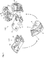
- FIG. 1 shows optionally how the mass of the housing 2 can be further reduced by manufacturing a microstructure 12.
- the microstructure has symbolically indicated webs and gaps, but is sufficiently stable in the corresponding section 6 of the housing 2.
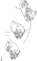
- FIG. 2 shows an alternative optimization of the housing 2 to monolithic construction M down in detail.
- the production optimization F takes place, in which a final configuration (CAD model) of the shape of the housing 2 is created on the basis of the automatically bionically optimized intermediate models (different results of the two different topology optimizations T).
- the achieved mass of the Monolithbauteils M is 484 grams, so still about 50 grams above that of the hybrid version H.
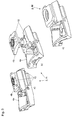
- FIG. 3 shows for the housing 2, the transition of the hybrid component H to an alternative monolithic component M according to the prior art.
- the housing 2 according to FIGS. 3a, b are parts of the transmission 10, that is, some gear components used.
- FIG. 3a shows a mounting position and FIG. 3b a partial exploded view.
- FIG. 3 shows the housing 2 in monolithic construction M using conventional manufacturing technology. This was the design according to FIG. 3a, b identical in pure steel construction adopted.
- the mass of the housing 2 according to Figure 3c is significantly higher than that of the housing 2 as Monolithbaumaschinemaschine M according to FIGS. 1 and 2 , since in particular no topology optimization T has taken place here.
Landscapes
- Engineering & Computer Science (AREA)
- Manufacturing & Machinery (AREA)
- Chemical & Material Sciences (AREA)
- Materials Engineering (AREA)
- Mechanical Engineering (AREA)
- General Engineering & Computer Science (AREA)
- Physics & Mathematics (AREA)
- Plasma & Fusion (AREA)
- General Details Of Gearings (AREA)
- Casings For Electric Apparatus (AREA)
- Powder Metallurgy (AREA)
Description
- Die Erfindung betrifft ein Gehäuse für ein Getriebe. Das Gehäuse dient zur Aufnahme des Getriebes, insbesondere von Zahnrädern und Wellen. Die Erfindung betrifft ein Gehäuse mit einem darin aufgenommenen Getriebe.
- Bei derartigen Gehäusen ist es in der Praxis üblich, verschiedene Abschnitte bzw. Teile des entsprechenden Gehäuses aus verschiedenen Materialien zu fertigen. Beispielsweise wird ein Teil des Gehäuses aus Stahl und ein anderer Teil des Gehäuses aus Aluminium gefertigt. Derartige Getriebe können bei tiefen Temperaturen, beispielsweise bei -40°C, stark erhöhte Reibmomente zeigen.
- Aus dem Stand der Technik ist es bekannt, additive Fertigungsverfahren zur Herstellung diverser Komponenten einzusetzen. Die
FR 3 016 407 A1 GB 2 521 391 A WO 2016/111896 A1 beschäftigt sich mit einer zumindest teilweise mit einem additiven Fertigungsverfahren hergestellten Struktur, in welcher ein Vibrationsdämpfer eingebettet ist. Es wird vorgeschlagen, die Struktur für Teile eines Helikopters, wie Getriebe, Gehäuse usw. einzusetzen. - Aufgabe der Erfindung ist es, ein verbessertes Gehäuse anzugeben.
- Die Aufgabe wird gelöst durch ein Gehäuse gemäß Patentanspruch 1. Bevorzugte oder vorteilhafte Ausführungsformen der Erfindung sowie andere Erfindungskategorien ergeben sich aus den weiteren Ansprüchen, der nachfolgenden Beschreibung sowie den beigefügten Figuren.
- Das Gehäuse ist ein Gehäuse für ein Getriebe. Das Gehäuse dient zur Aufnahme des Getriebes bzw. nimmt das Getriebe auf. Zumindest ein Abschnitt des Gehäuses ist mit Hilfe eines additiven Fertigungsverfahrens hergestellt. Entsprechend der Erfindung ist ein Abschnitt, der zumindest teilweise an das Getriebe oder eines Teils des Getriebes angrenzt, mit Hilfe eines additiven Fertigungsverfahrens hergestellt.
- Im Rahmen der vorliegenden Patentanmeldung steht der Begriff "additives Fertigungsverfahren" für Fertigungsverfahren, für welche in der Literatur eine Vielzahl von Bezeichnungen üblich sind. Derartige Fertigungsverfahren werden z.B. auch "generative Fertigungsverfahren", "additive manufacturing", "rapid prototyping", "rapid manufacturing" oder "3D-Druck" genannt. Eine Übersicht über Beispiele additiver Fertigungsverfahren findet sich beispielsweise in dem Dokument "'VDI Statusreport Additive Fertigungsverfahren September 2014', Verein deutscher Ingenieure e.V., Dr. Erik Marquardt, Fachbereich Produktionstechnik und Fertigungsverfahren, PDF-Datei zum kostenlosen Download unter www.vdi.de/statusadditiv".
- Durch Einsatz des additiven Fertigungsverfahrens können Strukturen, insbesondere Materialstärken beziehungsweise Wanddicken am Gehäuse realisiert werden, welche in dieser Ausführung bzw. Anordnung mit herkömmlichen Fertigungsverfahren nur äußerst aufwändig oder gar nicht herstellbar wären. So ist es insbesondere möglich, ein Gehäuse herzustellen, welches an jeder Stelle nur die entsprechende Materialstärke aufweist, welche notwendig ist, um gerade den dort zu erwartenden Belastungen standhalten zu können. So entstehen Abschnitte mit sehr geringen Wanddicken, so dass sich eine Gewichtseinsparung gegenüber herkömmlich gefertigten Gehäusen ergibt.
- Für die Auswahl des Gehäusematerials steht eine Reihe von Materialien zur Verfügung, welche mit additiven Fertigungsverfahren bearbeitbar sind. So kann insbesondere ein Material gewählt werden, welches bezüglich seiner Wärmeausdehnung für das einzusetzende Getriebe günstig ist, um Schwergängigkeit, erhöhte Reibung oder gar Verklemmungen beziehungsweise ungünstige Toleranzlagen über den gesamten spezifizierten Temperaturbereich zu verringern oder zu vermeiden.
- Das Gehäuse ist ein Gehäuse einer Rudermaschine für ein Leitwerk eines Fluggerätes. Die Rudermaschine enthält dabei das Getriebe. Das Fluggerät ist insbesondere ein Flugzeug, eine Flugwaffe oder ein Lenkflugkörper. Bei derartigen Gehäusen sind die oben genannten Vorteile, wie z.B. Leichtbaumöglichkeit, wegen der erzielbaren Gewichtsersparnis besonders vorteilhaft.
- Gemäß der Erfindung ist zumindest ein Abschnitt des Gehäuses, insbesondere das gesamte Gehäuse, aus einem Stahlwerkstoff gefertigt. Auch das Getriebe, insbesondere dessen Teile, wie Wellen und Zahnräder, ist entsprechend der Erfindung aus einem Stahlwerkstoff gefertigt.
- Die Erfindung beruht auf folgenden Überlegungen und Erkenntnissen: Aus der Praxis sind leichtbauende Getriebe, insbesondere Rudermaschinen, bekannt, welche meistens ein Gehäuse aus Aluminium aufweisen. Das eigentliche Getriebe bzw. die eigentlichen Getriebeelemente, wie etwa Zahnräder und Wellen, sind üblicherweise hoch belastet und aus Stahl hergestellt. Bei Temperaturgang kommt es aufgrund der unterschiedlichen Ausdehnungen zu Verklemmungen im Getriebe. Grund für die erhöhten Reibmomente im bekannten Gehäuse beziehungsweise dem bekannten Getriebe bzw. Rudermaschine sind die unterschiedlichen Werkstoffpaarungen von Gehäuse und Getriebe. Das Getriebe ist in der Regel aus Stahl gefertigt, um das Getriebe beziehungsweise die Zahnräder für die auftretenden hohen Belastungen auszulegen. Ein üblicher Temperaturbereich für die Gehäusespezifikation bei Rudermaschinen ist z.B. -55°C bis +80°C. Diejenigen Gehäuseteile, die nicht aus Stahl sondern z.B. aus Aluminium bestehen, weisen andere Wärmeausdehnungen auf. Dies führt im üblichen Temperaturbereich für die Gehäusespezifikation zu erhöhter Reibung oder Verklemmungen. Wünschenswert ist es, die Reibmomente über einen weiten Temperaturbereich, insbesondere den oben genannten Spezifikationsbereich, weitgehend konstant zu halten.
- Eine erste denkbare Lösung wäre der Einbau einer Heizung, um die Nachteile bei tiefen Temperaturen dadurch zu vermeiden, dass das Getriebe, insbesondere die Rudermaschine auf unkritische Temperaturen stabilisiert wird. Weiterhin wäre eine mögliche Lösung, das Gehäuse beziehungsweise das Getriebe aus Werkstoffen zumindest ähnlicher Wärmeausdehnung aufzubauen. Eine Möglichkeit wäre beispielsweise, das Gehäuse aus einer teuren Titanlegierung zu fertigen, was jedoch einen Kostennachteil bedeuten würde.
- Die Verwendung von Stahlwerkstoff scheidet insbesondere in der Luftfahrt in der Regel aus, da das Gewicht eines entsprechenden Getriebes zu hoch wird. Die erfinderische Idee besteht nun darin, ein additives Fertigungsverfahren in Verbindung mit einem Stahlwerkstoff einzusetzen. So kann der Stahlwerkstoff dünner als bisher möglich eingesetzt werden und so die dem Stahlwerkstoff eigene Gewichtsproblematik zumindest in ausreichendem Maße kompensiert werden. So können auch das gesamte Gehäuse oder entsprechend kritische Gehäuseabschnitte, insbesondere Abschnitte die zumindest teilweise an das Getriebe oder an Teile davon angrenzen, aus Stahlwerkstoff gefertigt werden. Hierbei können, wie oben erwähnt, Materialstärken gefertigt werden, die insgesamt zu einem Leichtbau-Stahlgehäuse führen, welches keine oder nur akzeptable Gewichtsnachteile mehr gegenüber einem bisherigen Gehäuse in Hybridbauweise, insbesondere aus Stahl und Aluminium, aufweist.
- Das Stahlgehäuse weist dann die identische Wärmeausdehnung wie ein Stahlgetriebe bzw. dessen Zahnräder auf, wodurch unterschiedliche Materialausdehnungen verhindert werden. Gemäß dieser Erfindungsvariante entsteht ein Gehäuse geringerer Komplexität und mit geringeren Kosten gegenüber bisherigen Ansätzen. Das Gehäuse kann leichtbauend ausgeführt werden. Es kann eine Zusammenfassung von üblichen Aluminium- und Stahlgehäusebauteilen zu einem monolithischen Stahlgehäuse erfolgen. Ein mehrteiliges Getriebe- bzw. Rudermaschinengehäuse, welches bisher aus gemischten Werkstoffen gefertigt wurde, kann nun als einteiliges Gehäuse ausgeführt werden, wobei gleichzeitig die Gefahr von Temperaturspannungen gebannt wird. Mit anderen Worten wird das Gehäuse also mit Verfahren der additiven Fertigung aufgebaut.
- Mit den erfindungsgemäßen additiven Fertigungsverfahren, welche neuesten Fertigungsmethoden entsprechen, können Getriebe- bzw. Rudermaschinengehäuse aus Stahl gleichen Gewichts und gleicher Steifigkeit wie bisherige Gehäuse aus Aluminium oder mit Aluminiumanteil hergestellt werden. Gemäß dieser Erfindungsvariante ist also ein temperaturspannungsfreies Leichtbaugehäuse realisierbar. Ein Aluminium- oder Hybridgehäuse, welches bisher üblich ist, kann aufgrund der neuartigen additiven Fertigungstechnologie durch ein gleich schweres und gleich steifes Stahlgehäuse realisiert werden. Sämtliche gestalterischen Freiheitsgrade additiver Fertigungsverfahren, zum Beispiel insbesondere des SLM-Verfahrens (selective laser melting), auch LBM (laser beam melting) genannt, können genutzt werden.
- Gemäß einer bevorzugten Ausführungsform umfasst das Gehäuse mehrere Gehäuseteile. Mindestens eines der Gehäuseteile ist mit Hilfe des additiven Fertigungsverfahrens hergestellt. So können beispielsweise unkritische konventionell zu fertigende Gehäuseteile mit herkömmlichen Fertigungsverfahren schnell und einfach hergestellt werden, komplexe oder besonders gewichtssparend auszuführende Gehäuseteile können mit Hilfe des additiven Fertigungsverfahrens hergestellt werden. So werden Kosten und Aufwand für das gesamte Gehäuse gesenkt.
- In einer alternativen Ausführungsform ist das Gehäuse einstückig ausgeführt. Das einstückige Gehäuse kann vollständig mit Hilfe eines additiven Fertigungsverfahrens hergestellt werden. Es ist aber auch möglich, mit additiven Fertigungsverfahren nur bestimmte Abschnitte des Gehäuses, insbesondere solche Abschnitte, die zumindest teilweise an das Getriebe angrenzen, zu fertigen und die restlichen Abschnitte herkömmlich herzustellen. Schlussendlich werden alle Abschnitte des Gehäuses dann einstückig verbunden, zum Beispiel verschweißt.
- In einer bevorzugten Ausführungsform ist das Gehäuse vollständig mit Hilfe des additiven Fertigungsverfahrens hergestellt. Dies gilt sowohl für ein einstückiges Gehäuse als auch für ein Gehäuse mit mehreren Gehäuseteilen. Insbesondere ist so nur ein einziges Fertigungsverfahren für das gesamte Gehäuse notwendig und das gesamte Gehäuse kann insbesondere bezüglich Wandstärken an allen Stellen mit geringstmöglicher Wandstärke bzw. gewichtssparender Struktur ausgeführt werden.
- In einer bevorzugten Ausführungsform weist zumindest ein Teil desjenigen Abschnitts des Gehäuses, welcher mit Hilfe des additiven Fertigungsverfahrens hergestellt ist, eine Mikrostruktur auf. Die Mikrostruktur - z.B. als o.g. gewichtssparende Struktur - enthält eine Vielzahl von Verbindungsstegen mit dazwischenliegenden Freiräumen. Der entsprechende Gehäuseabschnitt ist insbesondere als Mikrofachwerk ausgeführt, wie es zum Beispiel aus der
DE 10 2014 003 441 A1 bekannt ist. Eine derartige Mikrostruktur ist trotz ihrer Freiräume ausreichend stabil im Vergleich zu einem aus Vollmaterial hergestellten Gehäuseabschnitt, jedoch gewichtssparender. Insbesondere derartige Mikrostrukturen sind mit herkömmlichen Fertigungsverfahren nicht oder nur schwer herstellbar, durch das additive Fertigungsverfahren jedoch problemlos herstellbar. - In einer bevorzugten Ausführungsform ist das additive Fertigungsverfahren ein SLM- oder LBM-Verfahren. Diese Verfahren wurden bereits oben genannt und eignen sich insbesondere zur Verarbeitung von Stahlwerkstoffen und somit zur Herstellung von additiv gefertigten Stahlgehäusen mit den o.g. Vorteilen.
- In einer bevorzugten Ausführungsform ist das Gehäuse bionisch bzw. nach einem bionischen Ansatz konstruiert. Ein entsprechend bionischer Ansatz schafft in der Regel filigrane beziehungsweise organisch anmutende Strukturen, welche insbesondere als Mikrofachwerk, wie oben erläutert, ausgeführt werden können und eine Vielzahl von Hohlräumen zwischen Verbindungsstegen aufweisen. Beim bionischen Ansatz werden insbesondere in der Natur vorkommende Strukturen imitiert oder nachgeahmt, welche beispielsweise besonders stabil und zugleich auch besonders leicht sein können.
- Gemäß einer bevorzugten Variante dieser Ausführungsform ist das Gehäuse unter Verwendung mindestens zweier Topologieoptimierungen, insbesondere automatischer bionischer Optimierungsläufe mit unterschiedlichen Startparametern, konstruiert. Durch die beiden verschiedenen Optimierungsläufe werden in der Regel zwei verschiedene Gehäusestrukturen vorgeschlagen. Diese dienen dann als Anregungen für einen Konstrukteur, um ein gewichtssparendes, aber ausreichend stabiles Gehäuse - in der Regel als CAD-Modell - zu entwerfen.
- Die Aufgabe der Erfindung wird auch gelöst durch die Verwendung eines additiven Fertigungsverfahrens gemäß Patentanspruch 10. Das additive Fertigungsverfahren wird hierbei zur Herstellung des oben genannten erfindungsgemäßen Gehäuses verwendet. Die Verwendung sowie deren bevorzugte Ausführungsformen und deren Vorteile wurden sinngemäß bereits im Zusammenhang mit dem erfindungsgemäßen Gehäuse erläutert.
- Die Aspekte der Erfindung in ihren verschiedenen Kategorien einschließlich bevorzugter Ausführungsformen lassen sich wie folgt zusammenfassen:
Die erfindungsgemäßen Gehäuse können vollständig neu entworfen werden; alternativ ist es aber auch möglich, bekannte Gehäuseentwürfe bzw. -designs im Hinblick auf die Möglichkeiten der additiven Fertigungsverfahren zu optimieren, insbesondere Wandstärken an bestimmten Gehäuseabschnitten zu reduzieren und/oder bisherige massive Abschnitte als Mikrofachwerk auszuführen usw. Die Änderungen können insbesondere dort vorgenommen werden, wo dies bisher aufgrund der begrenzten Möglichkeiten herkömmlicher Fertigungsmethoden nicht möglich oder nicht wirtschaftlich war. Insbesondere können mit dem erfindungsgemäßen Gehäuse zukünftige Fluggeräteprojekte realisiert werden oder auch Upgrade-Programme existierender Baureihen durchgeführt werden. - Weitere Merkmale, Wirkungen und Vorteile der Erfindung ergeben sich aus der nachfolgenden Beschreibung eines bevorzugten Ausführungsbeispiels der Erfindung sowie der beigefügten Figuren. Dabei zeigen in einer schematischen Prinzipskizze:
- Fig. 1
- ein erfindungsgemäßes Gehäuse und dessen Entwurf anhand eines bestehenden Gehäuses,
- Fig. 2
- einen alternativen Entwurfsprozess für das erfindungsgemäße Gehäuse,
- Fig. 3
- die Übertragung des bestehenden Gehäuses aus
Fig. 1 in ein herkömmliches Stahlgehäuse. -
Figur 1 zeigt ein Gehäuse 2 gemäß der Erfindung, das ein Gehäuse 2 einer Rudermaschine für ein Leitwerk eines Fluggerätes - alle nicht dargestellt - ist. Das Gehäuse 2 dient zur Aufnahme eines in denFiguren 1 und2 nicht dargestellten Getriebes 10 der Rudermaschine. Das Gehäuse 2 ist in seiner Gesamtheit einstückig mit Hilfe eines additiven Fertigungsverfahrens, hier des SLM-Verfahrens, hergestellt. -
Figur 1 zeigt das Gehäuse 2 aus drei Ansichten a) bis c), wobei die jeweiligen Blickrichtungen für die Ansichten durch Pfeile und Großbuchstaben A-C dargestellt sind.Figur 1 zeigt auch einen Entwurfsprozess, welcher zur konkreten Ausführung des Gehäuses 2 führt. Der Entwurfsprozess beginnt bei einem bereits vorliegenden Entwurf für das Gehäuse 2 als Hybridbauteil H, bei dem ein erstes Gehäuseteil 4a des Gehäuses, hier ein Grundkörper bzw. eigentliches Gehäuse, aus Aluminium gefertigt ist. Ein zweites Gehäuseteil 4b, hier eine besonders belastete obere Abdeckung, ist aus Stahl gefertigt. Das bestehende Bauteil weist eine Masse von 430 Gramm auf und eine Verformung am Lagersitz von 0,09 Millimeter. - Das Problem des Gehäuses 2 als Hybridbauteil H, also in Hybridbauweise, besteht hier in der unterschiedlichen Wärmeausdehnung der Gehäuseteile 4a, b. Diese verursachen stark temperaturabhängige Veränderungen von Reibung beziehungsweise Getriebespiel in der endgültigen Rudermaschine, das heißt wenn das Getriebe 10 in das Gehäuse 2 eingesetzt ist. Das Gesamtgewicht von 430 Gramm setzt sich hierbei aus 140 Gramm für das Gehäuseteil 4b und 281 Gramm für das Gehäuseteil 4a sowie 9 Gramm für nicht dargestellte Gehäuseschrauben zusammen.
- Über eine Topologieoptimierung T erfolgt zunächst eine automatische Ermittlung hochbelasteter und weniger belasteter Abschnitte 6 des Gehäuses 2 anhand in der Fachwelt üblicher CAD-Methoden (Computer Aided Design), die hier nicht näher erläutert werden sollen.
- In einer anschließenden Fertigungsoptimierung F wird das Ergebnis der Topologieoptimierung ausgewertet bzw. genutzt. Vorliegend werden z.B. in weniger belasteten Abschnitten 6 des Gehäuses 2 Aussparungen 8 in das Design des Gehäuses 2 vorgesehen. Hierdurch wird Material eingespart. Die entstehende komplexe Bauteilgeometrie (CAD-Design) kann anhand des additiven Fertigungsverfahrens aus Stahl problemlos gefertigt werden. Im Ergebnis ergibt sich das Monolithbauteil M als Gehäuse 2, welches alleine aus Stahl besteht und eine Masse von ca. 480 Gramm bei einer Verformung des Lagersitzes von ebenfalls 0,09 Millimeter aufweist.
- Für das Gehäuse 2 in Monolithbauweise, also als Monolithbauteil M, ergibt sich ein homogenes Wärmeausdehnungsverhalten der Gehäusestruktur, keine nachteiligen Veränderungen bezüglich Steifigkeit und Gewicht gegenüber dem Hybridbauteil H, eine verbesserte Montierbarkeit und die Möglichkeit der Nutzung der gestalterischen Freiheitsgrade des additiven Fertigungsverfahrens, hier insbesondere des SLM-Verfahrens.
-
Figur 1 zeigt optional, wie die Masse des Gehäuses 2 durch Fertigung einer Mikrostruktur 12 weiter reduziert werden kann. Die Mikrostruktur weist symbolisch angedeutete Stege und Zwischenräume auf, ist jedoch im entsprechenden Abschnitt 6 des Gehäuses 2 ausreichend stabil. -
Figur 2 zeigt eine alternative Optimierung des Gehäuses 2 zur Monolithbauweise M hin im Detail. Ausgehend von dem bekannten Gehäuse 2 ausFig. 1 in Hybridbauweise werden zwei unterschiedliche Topologieoptimierungen T mit unterschiedlichen Startparametern als zwei automatische bionische Optimierungsläufe getätigt. Aus beiden Ergebnissen erfolgt die Fertigungsoptimierung F, bei der anhand der automatisch bionisch optimierten Zwischenmodelle (unterschiedliche Ergebnisse der beiden verschiedenen Topologieoptimierungen T) eine endgültige Ausgestaltung (CAD-Modell) der Form des Gehäuses 2 geschaffen wird. Die erzielte Masse des Monolithbauteils M liegt bei 484 Gramm, also noch ca. 50 Gramm über dem der Hybridversion H. -
Figur 3 zeigt für das Gehäuse 2 den Übergang des Hybridbauteils H zu einem alternativen Monolithbauteil M gemäß Stand der Technik. In das Gehäuse 2 gemäßFiguren 3a, b sind Teile des Getriebes 10, d.h. einige Getriebekomponenten, eingesetzt.Figur 3a zeigt eine Montageposition undFigur 3b eine teilweise Explosionsdarstellung.Figur 3 zeigt das Gehäuse 2 auch in Monolithbauweise M bei Verwendung herkömmlicher Fertigungstechnologie. hierzu wurde das Design gemäßFigur 3a, b identisch in reine Stahlbauweise übernommen. Die Masse des Gehäuses 2 gemäßFigur 3c liegt deutlich über derjenigen der Gehäuse 2 als Monolithbauteile M gemäßFiguren 1 und2 , da hier insbesondere keine Topologieoptimierung T stattgefunden hat. Insbesondere sind keine Aussparungen 8 im Monolithbauteil M gemäßFig. 3 vorhanden. -
- 2
- Gehäuse
- 4a, b
- Gehäuseteil
- 6
- Abschnitt
- 8
- Aussparung
- 10
- Getriebe
- 12
- Mikrostruktur
- F
- Fertigungsoptimierung
- H
- Hybridbauteil
- M
- Monolithbauteil
- T
- Topologieoptimierung
Claims (10)
- Gehäuse (2) einer Rudermaschine für ein Leitwerk eines Fluggerätes mit einem darin aufgenommenen Getriebe (10), wobeia) zumindest ein Abschnitt (6) des Gehäuses (2), der zumindest teilweise an das Getriebe (10) oder eines Teils des Getriebes (10) angrenzt, mit Hilfe eines additiven Fertigungsverfahrens hergestellt ist undb) der Abschnitt (6) und das Getriebe (10) aus einem Stahlwerkstoff gefertigt sind.
- Gehäuse (2) nach Anspruch 1,
wobei das gesamte Gehäuse (2), aus einem Stahlwerkstoff gefertigt ist. - Gehäuse (2) nach Anspruch 1 oder 2,
wobei das Gehäuse (2) mehrere Gehäuseteile (4a, 4b) umfasst, und mindestens eines der Gehäuseteile (4a, 4b) mit Hilfe des additiven Fertigungsverfahrens hergestellt ist. - Gehäuse (2) nach Anspruch 1 oder 2,
wobei das Gehäuse (2) einstückig ausgeführt ist. - Gehäuse (2) nach einem der vorhergehenden Ansprüche,
wobei das Gehäuse (2) vollständig mit Hilfe des additiven Fertigungsverfahrens hergestellt ist. - Gehäuse (2) nach einem der vorhergehenden Ansprüche,
wobei zumindest ein Teil des mit Hilfe des additiven Fertigungsverfahrens hergestellten Abschnitts (6) des Gehäuses (2) eine Mikrostruktur (12) aufweist, die eine Vielzahl von Verbindungsstegen mit dazwischenliegenden Freiräumen enthält. - Gehäuse (2) nach einem der vorhergehenden Ansprüche,
wobei das additive Fertigungsverfahren ein SLM oder LBM-Verfahren ist. - Gehäuse (2) nach einem der vorhergehenden Ansprüche,
wobei das Gehäuse (2) nach einem bionischen Ansatz konstruiert ist. - Gehäuse (2) nach Anspruch 8,
wobei das Gehäuse (2) unter Verwendung mindestens zweier unterschiedlicher Topologieoptimierungen (T) konstruiert ist. - Verwendung eines additiven Fertigungsverfahrens,
wobei das additive Fertigungsverfahren zur Herstellung eines Gehäuses (2) nach einem der vorhergehenden Ansprüche verwendet wird.
Applications Claiming Priority (1)
| Application Number | Priority Date | Filing Date | Title |
|---|---|---|---|
| DE102015013182.6A DE102015013182A1 (de) | 2015-10-10 | 2015-10-10 | Gehäuse für ein Getriebe und Verwendung eines additiven Fertigungsverfahrens |
Publications (2)
| Publication Number | Publication Date |
|---|---|
| EP3153255A1 EP3153255A1 (de) | 2017-04-12 |
| EP3153255B1 true EP3153255B1 (de) | 2019-08-21 |
Family
ID=57144704
Family Applications (1)
| Application Number | Title | Priority Date | Filing Date |
|---|---|---|---|
| EP16002130.9A Active EP3153255B1 (de) | 2015-10-10 | 2016-10-04 | Gehäuse für ein getriebe und verwendung eines additiven fertigungsverfahrens |
Country Status (3)
| Country | Link |
|---|---|
| EP (1) | EP3153255B1 (de) |
| DE (1) | DE102015013182A1 (de) |
| ES (1) | ES2749106T3 (de) |
Families Citing this family (3)
| Publication number | Priority date | Publication date | Assignee | Title |
|---|---|---|---|---|
| JP7063034B2 (ja) * | 2018-03-22 | 2022-05-09 | トヨタ自動車株式会社 | 積層造形方法 |
| CN111443605B (zh) * | 2020-04-01 | 2021-03-23 | 西安交通大学 | 构建仿生波动鳍推进运动控制方程及其参数整定优化方法 |
| DE102022103922A1 (de) | 2022-02-18 | 2023-08-24 | MTU Aero Engines AG | Hebel zum verstellen einer verstellschaufel |
Family Cites Families (6)
| Publication number | Priority date | Publication date | Assignee | Title |
|---|---|---|---|---|
| DE102011108957B4 (de) * | 2011-07-29 | 2013-07-04 | Mtu Aero Engines Gmbh | Verfahren zum Herstellen, Reparieren und/oder Austauschen eines Gehäuses, insbesondere eines Triebwerkgehäuses, sowie ein entsprechendes Gehäuse |
| DE102013214389A1 (de) * | 2013-07-23 | 2015-01-29 | MTU Aero Engines AG | Gehäusecontainment |
| GB2521391A (en) * | 2013-12-18 | 2015-06-24 | Skf Ab | A building block for a mechanical construction, the bearing and actuator |
| FR3016407B1 (fr) * | 2014-01-16 | 2016-02-19 | Hispano Suiza Sa | Boitier d'entrainement pour equipements |
| DE102014003441B4 (de) | 2014-03-10 | 2021-12-23 | Fraunhofer-Gesellschaft zur Förderung der angewandten Forschung e.V. | Verfahren zum Ausbilden eines Triebelements und Triebelement |
| EP3242763A4 (de) * | 2015-01-05 | 2018-08-29 | Sikorsky Aircraft Corporation | Integrierter schwingungsdämpfer für generativ gefertigte struktur und verfahren |
-
2015
- 2015-10-10 DE DE102015013182.6A patent/DE102015013182A1/de not_active Withdrawn
-
2016
- 2016-10-04 EP EP16002130.9A patent/EP3153255B1/de active Active
- 2016-10-04 ES ES16002130T patent/ES2749106T3/es active Active
Non-Patent Citations (1)
| Title |
|---|
| None * |
Also Published As
| Publication number | Publication date |
|---|---|
| ES2749106T3 (es) | 2020-03-19 |
| DE102015013182A1 (de) | 2017-04-13 |
| EP3153255A1 (de) | 2017-04-12 |
Similar Documents
| Publication | Publication Date | Title |
|---|---|---|
| DE102014003441B4 (de) | Verfahren zum Ausbilden eines Triebelements und Triebelement | |
| EP2940324B1 (de) | Lagerkäfig und lagereinrichtung mit einem derartigen lagerkäfig sowie verfahren zum ausbilden, reparieren und/oder austauschen eines solchen lagerkäfigs | |
| EP3423218B1 (de) | Verfahren zur modularen additiven herstellung eines bauteils und bauteil | |
| EP3621758B1 (de) | Verfahren für ein additiv herzustellendes bauteil mit vorbestimmter oberflächenstruktur | |
| DE102012102775B4 (de) | Schraubrad für eine elektromechanische Lenkvorrichtung | |
| EP2783775A2 (de) | Verwendung eines additiven Herstellungsverfahrens zur Herstellung eines Bauteils für ein Kraftfahrzeug | |
| EP3075471A1 (de) | Verfahren zum generativen herstellen eines gasturbinengehäuseteils | |
| EP3153255A1 (de) | Gehäuse für ein getriebe und verwendung eines additiven fertigungsverfahrens | |
| DE102010026839A1 (de) | Aerodynamische Verkleidungsvorrichtung, Flugzeug-Bauteilanordnung mit einer aerodynamischen Verkleidungsvorrichtung sowie Verfahren zur Montage eines solchen Verkleidungsteils | |
| WO2014195009A1 (de) | Zerspanungswerkzeug sowie verfahren zur herstellung eines zerspanungswerkzeug | |
| EP3625065A1 (de) | Verfahren zur herstellung eines verbindungselementes sowie verbindungselement | |
| EP4062134B1 (de) | Monolithisches wägesystem und verfahren zu dessen herstellung | |
| EP3421843B1 (de) | Planetenträger, giessverfahren und planetengetriebe | |
| DE102020134629A1 (de) | Verfahren zur Herstellung einer Außenverkleidung für Flugobjekte | |
| DE102013223752B4 (de) | Mengenflexibler Nadellagerkäfig | |
| DE102017119769A1 (de) | Lösbarer Halter für die additive Fertigung | |
| DE102011115954A1 (de) | Verfahren zum Herstellen einer Welle | |
| DE102010046887B4 (de) | Verschiebegelenk | |
| DE102017114618A1 (de) | Wälzlagerkäfig mit Notlaufeigenschaft | |
| DE102019121653A1 (de) | 3D-Druckverfahren von Multimaterialmischungen zur Erzeugung von Objekten, 3D-Druck-Fertigungsanlage für die Erzeugung von Objekten mit Multimaterialmischungen mittels Laserstrahlschmelzen, Objekt | |
| DE102015004983A1 (de) | Trägerelement zum Aufnehmen von Kräften in einem Fahrzeug | |
| AT527235B1 (de) | Getriebe | |
| DE112014001488T5 (de) | Abgasturbolader | |
| DE102014006771A1 (de) | Umformwerkzeug zum Umformen, insbesondere Falzen, eines Bauteils sowie Verfahren zum Herstellen eines solchen Umformwerkzeugs | |
| DE102020201621A1 (de) | Strategie zum Trennen von Bauteilen in der additiven Herstellung |
Legal Events
| Date | Code | Title | Description |
|---|---|---|---|
| PUAI | Public reference made under article 153(3) epc to a published international application that has entered the european phase |
Free format text: ORIGINAL CODE: 0009012 |
|
| STAA | Information on the status of an ep patent application or granted ep patent |
Free format text: STATUS: THE APPLICATION HAS BEEN PUBLISHED |
|
| AK | Designated contracting states |
Kind code of ref document: A1 Designated state(s): AL AT BE BG CH CY CZ DE DK EE ES FI FR GB GR HR HU IE IS IT LI LT LU LV MC MK MT NL NO PL PT RO RS SE SI SK SM TR |
|
| AX | Request for extension of the european patent |
Extension state: BA ME |
|
| STAA | Information on the status of an ep patent application or granted ep patent |
Free format text: STATUS: REQUEST FOR EXAMINATION WAS MADE |
|
| 17P | Request for examination filed |
Effective date: 20170828 |
|
| RBV | Designated contracting states (corrected) |
Designated state(s): AL AT BE BG CH CY CZ DE DK EE ES FI FR GB GR HR HU IE IS IT LI LT LU LV MC MK MT NL NO PL PT RO RS SE SI SK SM TR |
|
| REG | Reference to a national code |
Ref country code: DE Ref legal event code: R079 Ref document number: 502016006148 Country of ref document: DE Free format text: PREVIOUS MAIN CLASS: B22F0003105000 Ipc: B64C0013340000 |
|
| GRAP | Despatch of communication of intention to grant a patent |
Free format text: ORIGINAL CODE: EPIDOSNIGR1 |
|
| STAA | Information on the status of an ep patent application or granted ep patent |
Free format text: STATUS: GRANT OF PATENT IS INTENDED |
|
| RIC1 | Information provided on ipc code assigned before grant |
Ipc: B22F 3/105 20060101ALI20190308BHEP Ipc: B22F 7/06 20060101ALI20190308BHEP Ipc: F16H 57/032 20120101ALI20190308BHEP Ipc: B22F 5/10 20060101ALI20190308BHEP Ipc: B64C 13/34 20060101AFI20190308BHEP Ipc: B33Y 80/00 20150101ALI20190308BHEP |
|
| INTG | Intention to grant announced |
Effective date: 20190326 |
|
| GRAS | Grant fee paid |
Free format text: ORIGINAL CODE: EPIDOSNIGR3 |
|
| GRAA | (expected) grant |
Free format text: ORIGINAL CODE: 0009210 |
|
| STAA | Information on the status of an ep patent application or granted ep patent |
Free format text: STATUS: THE PATENT HAS BEEN GRANTED |
|
| AK | Designated contracting states |
Kind code of ref document: B1 Designated state(s): AL AT BE BG CH CY CZ DE DK EE ES FI FR GB GR HR HU IE IS IT LI LT LU LV MC MK MT NL NO PL PT RO RS SE SI SK SM TR |
|
| REG | Reference to a national code |
Ref country code: GB Ref legal event code: FG4D Free format text: NOT ENGLISH |
|
| REG | Reference to a national code |
Ref country code: CH Ref legal event code: EP |
|
| REG | Reference to a national code |
Ref country code: DE Ref legal event code: R096 Ref document number: 502016006148 Country of ref document: DE |
|
| REG | Reference to a national code |
Ref country code: AT Ref legal event code: REF Ref document number: 1169453 Country of ref document: AT Kind code of ref document: T Effective date: 20190915 |
|
| REG | Reference to a national code |
Ref country code: IE Ref legal event code: FG4D Free format text: LANGUAGE OF EP DOCUMENT: GERMAN |
|
| REG | Reference to a national code |
Ref country code: SE Ref legal event code: TRGR |
|
| REG | Reference to a national code |
Ref country code: LT Ref legal event code: MG4D |
|
| REG | Reference to a national code |
Ref country code: NL Ref legal event code: MP Effective date: 20190821 |
|
| REG | Reference to a national code |
Ref country code: NO Ref legal event code: T2 Effective date: 20190821 |
|
| PG25 | Lapsed in a contracting state [announced via postgrant information from national office to epo] |
Ref country code: PT Free format text: LAPSE BECAUSE OF FAILURE TO SUBMIT A TRANSLATION OF THE DESCRIPTION OR TO PAY THE FEE WITHIN THE PRESCRIBED TIME-LIMIT Effective date: 20191223 Ref country code: HR Free format text: LAPSE BECAUSE OF FAILURE TO SUBMIT A TRANSLATION OF THE DESCRIPTION OR TO PAY THE FEE WITHIN THE PRESCRIBED TIME-LIMIT Effective date: 20190821 Ref country code: LT Free format text: LAPSE BECAUSE OF FAILURE TO SUBMIT A TRANSLATION OF THE DESCRIPTION OR TO PAY THE FEE WITHIN THE PRESCRIBED TIME-LIMIT Effective date: 20190821 Ref country code: BG Free format text: LAPSE BECAUSE OF FAILURE TO SUBMIT A TRANSLATION OF THE DESCRIPTION OR TO PAY THE FEE WITHIN THE PRESCRIBED TIME-LIMIT Effective date: 20191121 Ref country code: NL Free format text: LAPSE BECAUSE OF FAILURE TO SUBMIT A TRANSLATION OF THE DESCRIPTION OR TO PAY THE FEE WITHIN THE PRESCRIBED TIME-LIMIT Effective date: 20190821 Ref country code: FI Free format text: LAPSE BECAUSE OF FAILURE TO SUBMIT A TRANSLATION OF THE DESCRIPTION OR TO PAY THE FEE WITHIN THE PRESCRIBED TIME-LIMIT Effective date: 20190821 |
|
| PG25 | Lapsed in a contracting state [announced via postgrant information from national office to epo] |
Ref country code: RS Free format text: LAPSE BECAUSE OF FAILURE TO SUBMIT A TRANSLATION OF THE DESCRIPTION OR TO PAY THE FEE WITHIN THE PRESCRIBED TIME-LIMIT Effective date: 20190821 Ref country code: IS Free format text: LAPSE BECAUSE OF FAILURE TO SUBMIT A TRANSLATION OF THE DESCRIPTION OR TO PAY THE FEE WITHIN THE PRESCRIBED TIME-LIMIT Effective date: 20191221 Ref country code: LV Free format text: LAPSE BECAUSE OF FAILURE TO SUBMIT A TRANSLATION OF THE DESCRIPTION OR TO PAY THE FEE WITHIN THE PRESCRIBED TIME-LIMIT Effective date: 20190821 Ref country code: AL Free format text: LAPSE BECAUSE OF FAILURE TO SUBMIT A TRANSLATION OF THE DESCRIPTION OR TO PAY THE FEE WITHIN THE PRESCRIBED TIME-LIMIT Effective date: 20190821 Ref country code: GR Free format text: LAPSE BECAUSE OF FAILURE TO SUBMIT A TRANSLATION OF THE DESCRIPTION OR TO PAY THE FEE WITHIN THE PRESCRIBED TIME-LIMIT Effective date: 20191122 |
|
| REG | Reference to a national code |
Ref country code: ES Ref legal event code: FG2A Ref document number: 2749106 Country of ref document: ES Kind code of ref document: T3 Effective date: 20200319 |
|
| PG25 | Lapsed in a contracting state [announced via postgrant information from national office to epo] |
Ref country code: TR Free format text: LAPSE BECAUSE OF FAILURE TO SUBMIT A TRANSLATION OF THE DESCRIPTION OR TO PAY THE FEE WITHIN THE PRESCRIBED TIME-LIMIT Effective date: 20190821 |
|
| PG25 | Lapsed in a contracting state [announced via postgrant information from national office to epo] |
Ref country code: EE Free format text: LAPSE BECAUSE OF FAILURE TO SUBMIT A TRANSLATION OF THE DESCRIPTION OR TO PAY THE FEE WITHIN THE PRESCRIBED TIME-LIMIT Effective date: 20190821 Ref country code: RO Free format text: LAPSE BECAUSE OF FAILURE TO SUBMIT A TRANSLATION OF THE DESCRIPTION OR TO PAY THE FEE WITHIN THE PRESCRIBED TIME-LIMIT Effective date: 20190821 Ref country code: DK Free format text: LAPSE BECAUSE OF FAILURE TO SUBMIT A TRANSLATION OF THE DESCRIPTION OR TO PAY THE FEE WITHIN THE PRESCRIBED TIME-LIMIT Effective date: 20190821 Ref country code: PL Free format text: LAPSE BECAUSE OF FAILURE TO SUBMIT A TRANSLATION OF THE DESCRIPTION OR TO PAY THE FEE WITHIN THE PRESCRIBED TIME-LIMIT Effective date: 20190821 |
|
| PG25 | Lapsed in a contracting state [announced via postgrant information from national office to epo] |
Ref country code: CZ Free format text: LAPSE BECAUSE OF FAILURE TO SUBMIT A TRANSLATION OF THE DESCRIPTION OR TO PAY THE FEE WITHIN THE PRESCRIBED TIME-LIMIT Effective date: 20190821 Ref country code: IS Free format text: LAPSE BECAUSE OF FAILURE TO SUBMIT A TRANSLATION OF THE DESCRIPTION OR TO PAY THE FEE WITHIN THE PRESCRIBED TIME-LIMIT Effective date: 20200224 Ref country code: MC Free format text: LAPSE BECAUSE OF FAILURE TO SUBMIT A TRANSLATION OF THE DESCRIPTION OR TO PAY THE FEE WITHIN THE PRESCRIBED TIME-LIMIT Effective date: 20190821 Ref country code: SK Free format text: LAPSE BECAUSE OF FAILURE TO SUBMIT A TRANSLATION OF THE DESCRIPTION OR TO PAY THE FEE WITHIN THE PRESCRIBED TIME-LIMIT Effective date: 20190821 Ref country code: SM Free format text: LAPSE BECAUSE OF FAILURE TO SUBMIT A TRANSLATION OF THE DESCRIPTION OR TO PAY THE FEE WITHIN THE PRESCRIBED TIME-LIMIT Effective date: 20190821 |
|
| REG | Reference to a national code |
Ref country code: CH Ref legal event code: PL |
|
| REG | Reference to a national code |
Ref country code: DE Ref legal event code: R097 Ref document number: 502016006148 Country of ref document: DE |
|
| PLBE | No opposition filed within time limit |
Free format text: ORIGINAL CODE: 0009261 |
|
| STAA | Information on the status of an ep patent application or granted ep patent |
Free format text: STATUS: NO OPPOSITION FILED WITHIN TIME LIMIT |
|
| PG2D | Information on lapse in contracting state deleted |
Ref country code: IS |
|
| PG25 | Lapsed in a contracting state [announced via postgrant information from national office to epo] |
Ref country code: LI Free format text: LAPSE BECAUSE OF NON-PAYMENT OF DUE FEES Effective date: 20191031 Ref country code: LU Free format text: LAPSE BECAUSE OF NON-PAYMENT OF DUE FEES Effective date: 20191004 Ref country code: CH Free format text: LAPSE BECAUSE OF NON-PAYMENT OF DUE FEES Effective date: 20191031 |
|
| 26N | No opposition filed |
Effective date: 20200603 |
|
| REG | Reference to a national code |
Ref country code: BE Ref legal event code: MM Effective date: 20191031 |
|
| PG25 | Lapsed in a contracting state [announced via postgrant information from national office to epo] |
Ref country code: BE Free format text: LAPSE BECAUSE OF NON-PAYMENT OF DUE FEES Effective date: 20191031 Ref country code: SI Free format text: LAPSE BECAUSE OF FAILURE TO SUBMIT A TRANSLATION OF THE DESCRIPTION OR TO PAY THE FEE WITHIN THE PRESCRIBED TIME-LIMIT Effective date: 20190821 |
|
| PG25 | Lapsed in a contracting state [announced via postgrant information from national office to epo] |
Ref country code: IE Free format text: LAPSE BECAUSE OF NON-PAYMENT OF DUE FEES Effective date: 20191004 |
|
| PG25 | Lapsed in a contracting state [announced via postgrant information from national office to epo] |
Ref country code: CY Free format text: LAPSE BECAUSE OF FAILURE TO SUBMIT A TRANSLATION OF THE DESCRIPTION OR TO PAY THE FEE WITHIN THE PRESCRIBED TIME-LIMIT Effective date: 20190821 |
|
| PG25 | Lapsed in a contracting state [announced via postgrant information from national office to epo] |
Ref country code: HU Free format text: LAPSE BECAUSE OF FAILURE TO SUBMIT A TRANSLATION OF THE DESCRIPTION OR TO PAY THE FEE WITHIN THE PRESCRIBED TIME-LIMIT; INVALID AB INITIO Effective date: 20161004 Ref country code: MT Free format text: LAPSE BECAUSE OF FAILURE TO SUBMIT A TRANSLATION OF THE DESCRIPTION OR TO PAY THE FEE WITHIN THE PRESCRIBED TIME-LIMIT Effective date: 20190821 |
|
| PG25 | Lapsed in a contracting state [announced via postgrant information from national office to epo] |
Ref country code: MK Free format text: LAPSE BECAUSE OF FAILURE TO SUBMIT A TRANSLATION OF THE DESCRIPTION OR TO PAY THE FEE WITHIN THE PRESCRIBED TIME-LIMIT Effective date: 20190821 |
|
| REG | Reference to a national code |
Ref country code: AT Ref legal event code: MM01 Ref document number: 1169453 Country of ref document: AT Kind code of ref document: T Effective date: 20211004 |
|
| PG25 | Lapsed in a contracting state [announced via postgrant information from national office to epo] |
Ref country code: AT Free format text: LAPSE BECAUSE OF NON-PAYMENT OF DUE FEES Effective date: 20211004 |
|
| PGFP | Annual fee paid to national office [announced via postgrant information from national office to epo] |
Ref country code: DE Payment date: 20251204 Year of fee payment: 10 |
|
| PGFP | Annual fee paid to national office [announced via postgrant information from national office to epo] |
Ref country code: GB Payment date: 20251022 Year of fee payment: 10 |
|
| PGFP | Annual fee paid to national office [announced via postgrant information from national office to epo] |
Ref country code: NO Payment date: 20251024 Year of fee payment: 10 |
|
| PGFP | Annual fee paid to national office [announced via postgrant information from national office to epo] |
Ref country code: IT Payment date: 20251024 Year of fee payment: 10 |
|
| PGFP | Annual fee paid to national office [announced via postgrant information from national office to epo] |
Ref country code: FR Payment date: 20251030 Year of fee payment: 10 |
|
| PGFP | Annual fee paid to national office [announced via postgrant information from national office to epo] |
Ref country code: SE Payment date: 20251021 Year of fee payment: 10 |
|
| PGFP | Annual fee paid to national office [announced via postgrant information from national office to epo] |
Ref country code: ES Payment date: 20251210 Year of fee payment: 10 |