EP3153229A1 - Contact-free thermoforming of fiber bundles - Google Patents
Contact-free thermoforming of fiber bundles Download PDFInfo
- Publication number
- EP3153229A1 EP3153229A1 EP15188520.9A EP15188520A EP3153229A1 EP 3153229 A1 EP3153229 A1 EP 3153229A1 EP 15188520 A EP15188520 A EP 15188520A EP 3153229 A1 EP3153229 A1 EP 3153229A1
- Authority
- EP
- European Patent Office
- Prior art keywords
- bundle
- hollow fiber
- fiber membranes
- tubular casing
- annular zone
- Prior art date
- Legal status (The legal status is an assumption and is not a legal conclusion. Google has not performed a legal analysis and makes no representation as to the accuracy of the status listed.)
- Withdrawn
Links
- 239000000835 fiber Substances 0.000 title claims description 77
- 238000003856 thermoforming Methods 0.000 title abstract description 27
- 238000000034 method Methods 0.000 claims abstract description 37
- 239000012510 hollow fiber Substances 0.000 claims abstract description 36
- 239000012528 membrane Substances 0.000 claims abstract description 30
- 238000004519 manufacturing process Methods 0.000 claims abstract description 10
- 230000005855 radiation Effects 0.000 claims description 25
- 238000005520 cutting process Methods 0.000 claims description 8
- 238000002844 melting Methods 0.000 claims description 5
- 230000008018 melting Effects 0.000 claims description 5
- 238000007789 sealing Methods 0.000 claims description 3
- 238000004382 potting Methods 0.000 description 9
- 238000004804 winding Methods 0.000 description 7
- 239000012530 fluid Substances 0.000 description 4
- 238000010438 heat treatment Methods 0.000 description 4
- 150000001875 compounds Chemical class 0.000 description 3
- 230000015572 biosynthetic process Effects 0.000 description 2
- 239000000463 material Substances 0.000 description 2
- 238000005266 casting Methods 0.000 description 1
- 239000003795 chemical substances by application Substances 0.000 description 1
- 210000000078 claw Anatomy 0.000 description 1
- 238000011109 contamination Methods 0.000 description 1
- -1 e.g. Substances 0.000 description 1
- 238000005194 fractionation Methods 0.000 description 1
- 238000012423 maintenance Methods 0.000 description 1
- 230000013011 mating Effects 0.000 description 1
- 239000002245 particle Substances 0.000 description 1
- 229920002635 polyurethane Polymers 0.000 description 1
- 239000004814 polyurethane Substances 0.000 description 1
Images

Classifications
-
- B—PERFORMING OPERATIONS; TRANSPORTING
- B01—PHYSICAL OR CHEMICAL PROCESSES OR APPARATUS IN GENERAL
- B01D—SEPARATION
- B01D63/00—Apparatus in general for separation processes using semi-permeable membranes
- B01D63/02—Hollow fibre modules
-
- B—PERFORMING OPERATIONS; TRANSPORTING
- B01—PHYSICAL OR CHEMICAL PROCESSES OR APPARATUS IN GENERAL
- B01D—SEPARATION
- B01D61/00—Processes of separation using semi-permeable membranes, e.g. dialysis, osmosis or ultrafiltration; Apparatus, accessories or auxiliary operations specially adapted therefor
- B01D61/14—Ultrafiltration; Microfiltration
- B01D61/18—Apparatus therefor
-
- B—PERFORMING OPERATIONS; TRANSPORTING
- B01—PHYSICAL OR CHEMICAL PROCESSES OR APPARATUS IN GENERAL
- B01D—SEPARATION
- B01D63/00—Apparatus in general for separation processes using semi-permeable membranes
- B01D63/02—Hollow fibre modules
- B01D63/021—Manufacturing thereof
- B01D63/022—Encapsulating hollow fibres
- B01D63/0223—Encapsulating hollow fibres by fixing the hollow fibres prior to encapsulation
-
- B—PERFORMING OPERATIONS; TRANSPORTING
- B01—PHYSICAL OR CHEMICAL PROCESSES OR APPARATUS IN GENERAL
- B01D—SEPARATION
- B01D63/00—Apparatus in general for separation processes using semi-permeable membranes
- B01D63/02—Hollow fibre modules
- B01D63/021—Manufacturing thereof
- B01D63/0233—Manufacturing thereof forming the bundle
-
- B—PERFORMING OPERATIONS; TRANSPORTING
- B01—PHYSICAL OR CHEMICAL PROCESSES OR APPARATUS IN GENERAL
- B01D—SEPARATION
- B01D63/00—Apparatus in general for separation processes using semi-permeable membranes
- B01D63/02—Hollow fibre modules
- B01D63/024—Hollow fibre modules with a single potted end
-
- B—PERFORMING OPERATIONS; TRANSPORTING
- B01—PHYSICAL OR CHEMICAL PROCESSES OR APPARATUS IN GENERAL
- B01D—SEPARATION
- B01D69/00—Semi-permeable membranes for separation processes or apparatus characterised by their form, structure or properties; Manufacturing processes specially adapted therefor
- B01D69/08—Hollow fibre membranes
-
- B—PERFORMING OPERATIONS; TRANSPORTING
- B01—PHYSICAL OR CHEMICAL PROCESSES OR APPARATUS IN GENERAL
- B01D—SEPARATION
- B01D2313/00—Details relating to membrane modules or apparatus
- B01D2313/02—Specific tightening or locking mechanisms
- B01D2313/025—Specific membrane holders
-
- B—PERFORMING OPERATIONS; TRANSPORTING
- B01—PHYSICAL OR CHEMICAL PROCESSES OR APPARATUS IN GENERAL
- B01D—SEPARATION
- B01D2313/00—Details relating to membrane modules or apparatus
- B01D2313/04—Specific sealing means
-
- B—PERFORMING OPERATIONS; TRANSPORTING
- B01—PHYSICAL OR CHEMICAL PROCESSES OR APPARATUS IN GENERAL
- B01D—SEPARATION
- B01D2313/00—Details relating to membrane modules or apparatus
- B01D2313/08—Flow guidance means within the module or the apparatus
-
- B—PERFORMING OPERATIONS; TRANSPORTING
- B01—PHYSICAL OR CHEMICAL PROCESSES OR APPARATUS IN GENERAL
- B01D—SEPARATION
- B01D2313/00—Details relating to membrane modules or apparatus
- B01D2313/10—Specific supply elements
Definitions
- the present disclosure relates to processes for the production of capillary dialyzers.
- the processes involve contact-free thermoforming of bundles of hollow fiber membranes.
- the present disclosure also relates to an apparatus for contact-free thermoforming of bundles of hollow fiber membranes.
- US 4 341 005 A discloses a process for the production of hollow fiber fluid fractionation cells which involves placing a series of half sections of the longitudinal walls of the cell on the periphery of a winding wheel; winding fluid-filled permeable hollow fibers thereabout until the section is full or slightly over-full; placing another mating half shell over each fiber-filled section on the wheel and assembling the cell core; cutting the courses between each section and draining the fluid therefrom; putting an initial fluid potting compound about the courses of fibers and centrifugally casting the potting compound about the fibers at each end of the cell; and cutting the fibers at each end within the area of the potting compound to re-expose the hollow cores thereof.
- JP 2003/062433 A discloses a method for manufacturing a hollow fiber membrane module capable of efficiently performing the potting of the end part of a hollow fiber membrane bundle without infiltrating a potting agent into the hollow fiber membranes.
- the hollow fiber membrane bundle is inserted into the cylindrical case so that the end part thereof protrudes from the cylindrical case; the end part is collapsed and sealed to be potted to the opening of the cylindrical case; and the collapsed and sealed part is subsequently cut off.
- WO 2004/086554 A2 discloses a method and apparatus for manufacturing hollow fiber membrane filters which employs a non-contact heat source to melt the tips of the hollow fibers to prevent potting material from entering the fibers.
- a hot plate is moved into position opposite and very close to the ends of the fibers in a bundle and closed in on the face of the fiber bundle to melt the ends of all the fibers in the bundle and seal them.
- the present disclosure provides processes for the production of capillary dialyzers comprising a bundle of hollow fiber membranes.
- the processes involve melting together fibers on a perimeter of an end of a fiber bundle so that a contiguous annular zone is formed on the perimeter of the bundle.
- the melting is effected by radiation heating of a circumference of an end of the fiber bundle.
- a process for the production of capillary dialyzers involves feeding dry hollow fibers to a winding wheel and winding these in sleeve lower parts arranged on the outer circumference of the winding wheel by turning the wheel. As soon as the desired fiber bundle thickness or fiber bundle size has been reached, the winding wheel is stopped and the sleeve upper parts are placed on the sleeve lower parts and fixed there. Subsequently, the hollow fibers are cut between the sleeves (11); and the sleeves (11) containing a fiber bundle (10) are removed from the winding wheel.
- thermoforming prior to transfer of a fiber bundle (10) from a sleeve (11) into a tubular filter casing (15), the fibers on the perimeter of a first end of the fiber bundle (10) are melted together (this operation is subsequently referred to as "thermoforming") so that a contiguous annular zone (13) is formed on a perimeter of the fiber bundle (10) ( Fig. 3a ).
- the melting is effected by radiation heating of a circumference of the first end of the fiber bundle. As the heating radiation source does not touch the fiber bundle (10) during the thermoforming step, the process is referred to as "contact-free thermoforming" in the present disclosure.
- a contiguous annular zone (13) is formed on a perimeter of the fiber bundle (10).
- the fibers remain unchanged, i.e., their ends are not melted and the fibers remain open.
- Thermoforming thus is clearly distinct from prior art heat-sealing processes such as the process disclosed by WO 2004/086554 A2 , or heat-sealing of the fiber ends by a hot blade or hot wire, which produce a disc-shaped fused zone on an end face of the fiber bundle.
- the contiguous annular zone (13) of the fiber bundle (10) simplifies transfer of the fiber bundle (10) into the tubular casing (15). As the position of the fiber ends on the perimeter of the bundle is fixed, and no fibers protrude from the perimeter of the bundle, formation of kinks and loops is avoided. Additionally, the transfer tool (14) does not need to engage all fibers on the perimeter.
- the diameter of the contiguous annular zone (13) is smaller than the initial diameter of the fiber bundle (10), and also smaller than the inner diameter of the tubular casing (15), the transfer is further facilitated, as less force is necessary to pull the fiber bundle (10) into the tubular casing (15). This in turn reduces the risk of fibers rupturing during the transfer of the fiber bundle. Both factors result in reduction of scrap.
- thermoforming is also performed on the second end of the fiber bundle (10).
- a thermoforming tool comprising a radiation source (17) produces a contiguous annular zone (18) on the perimeter of the second end of the fiber bundle (10) ( Fig. 3c ).
- the diameter of the fiber bundle (10) is reduced to from 70 to 90% of its initial value in the contiguous annular zone (13,18) (the thermoformed zone) during thermoforming.
- the contiguous annular zone (13,18) produced by the thermoforming process has a thickness of 0.1 to less than 1 mm, and a length of 2 to 20 mm in longitudinal direction of the bundle.
- thermoforming is effected by radiation heating.
- the circumference of an end of a fiber bundle (10) is irradiated with a suitable radiation source (12,17) which produces, for instance, microwave, UV, or IR radiation.
- a suitable radiation source (12,17) which produces, for instance, microwave, UV, or IR radiation.
- IR radiation is used to effect thermoforming.
- the radiation source (12,17) has a power in the range of from 1000 to 2500 W, for instance, from 1500 to 2000 W.
- the circumference of an end of a fiber bundle (10) is irradiated for a time in the range of from 1 sec to 20 seconds, for instance, 3 to 15 seconds, particularly 5 to 10 seconds, to produce a contiguous annular zone (13,18).
- thermoforming of a first end of a fiber bundle (10) is schematically shown in Fig. 3a.
- a thermoforming tool comprising a radiation source (12) produces a contiguous annular zone (13) on a perimeter of the first end of the fiber bundle (10).
- the fiber bundle (10) then is transferred into a tubular filter casing (15) ( Fig. 3b ).
- the tubular filter casing (15) is equipped with potting sleeves (16) at both ends.
- the length of the fiber bundle (10) is greater than the length of the tubular casing (15), so that both ends of the fiber bundle (10) protrude from the tubular casing (15) after the transfer.
- the thermoformed zone (13) of the fiber bundle (10) is entirely outside the tubular casing (15).
- the transfer is carried out by a tool (14), e.g., a transfer claw.
- the tool (14) reaches through the tubular casing (15); engages the contiguous annular zone (13) on the first end of the bundle (10) of hollow fiber membranes; pulls the bundle (10) of hollow fiber membranes into the tubular casing (15); and continues to pull until the first end of the bundle (10) of hollow fiber membranes inclusive of the entire contiguous annular zone (13) protrudes from the tubular casing (15).
- thermoforming is also performed on the second end of the fiber bundle (10) protruding from the tubular casing (15) after transfer of the fiber bundle (10) into the tubular casing (15) ( Fig. 3c ).
- a thermoforming tool comprising a radiation source (17) produces a contiguous annular zone (18) on a perimeter of the second end of the fiber bundle (10).
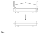
- the portions of the bundle of hollow fiber membranes (10) protruding from the tubular casing (15) are cut off with a cutting tool (19) ( Fig. 4 ) prior to the next stage of the dialyzer production process, which involves the formation of end walls within the tubular casing (15) by embedding the ends of the fiber bundle (10) in a potting material, e.g., polyurethane.
- a cutting tool (19) Fig. 4
- a potting material e.g., polyurethane.
- the end of the fiber bundle (10) is cut off with a blade subsequently to the thermoforming and transfer steps.
- the end of the fiber bundle is cut and the fiber ends are heat-sealed with a hot blade or a hot wire subsequently to the thermoforming and transfer steps.
- thermoforming When a thermoformed end of the fiber bundle (10) is cut off, the cut-off forms a contiguous slice, while otherwise a multitude of small fiber pieces is generated.
- thermoforming also results in less particle generation and less contamination of the workplace and equipment; less maintenance is required in the area where the transfer and cutting steps are performed.
- the present disclosure also provides an apparatus for forming a contiguous annular zone (13,18) on a perimeter of an end of a bundle (10) of hollow fiber membranes (a "thermoforming tool").
- the apparatus comprises a radiation source (12,17) configured to irradiate a circumference of said end of the bundle (10).
- the radiation source (12,17) is an IR emitter.
- One embodiment of the apparatus employs an IR emitter having the shape of an omega.
- the omega has an inner diameter in the range of from 30 to 130 mm, for instance, 60 to 100 mm.
- suitable IR emitters include Omega Infrared Emitters available from Heraeus Noblelight GmbH (63801 Kleinostheim, Germany).
- an Omega Infrared Emitter having an outer diameter of 80 mm and a power of 1500 W is used.
- the apparatus comprises a sliding carriage (1) with a tray (2) for mounting the fiber bundle (10).
- a two-part heat sink (3) is provided for enclosing the fiber bundle (10) at a position near its end.
- the apparatus comprises a radiation source (12) which is an omega-shaped IR emitter mounted in a fixture in vertical position. The center of the IR emitter is aligned with the longitudinal axis of the fiber bundle (10) on the tray (2).
- the fiber bundle (10) first is mounted on the tray (2) and the heat sink (3) is closed around the fiber bundle (10) at apposition near its end, leaving a portion having a length of 5 mm to 20 mm, for instance, 5 to 15 mm, e.g., 5 to 10 mm, or 10 to 15 mm, to protrude from the heat sink (3).
- the heat sink (3) is configured to shield the non-protruding portion of the fiber bundle (10) from the radiation emitted by radiation source (12).
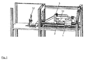
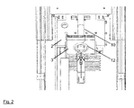
- the sliding carriage (1) is moved from a starting position (as shown in Fig. 1 ) into an end position (as shown in Fig. 2 ) close to the radiation source (12).
- the fibers on the perimeter of the fiber bundle (10) are melted together, thereby forming a contiguous annular zone on the perimeter of the fiber bundle.
- the bundle remains in the end position for a time in the range of from 3 to 15 seconds, for instance, 5 to 10 seconds, and then the sliding carriage (1) is moved back into the starting position, the heat sink (3) is opened and the fiber bundle (10) is removed from the tray (2). After transfer of the bundle into a tubular filter casing (15), the procedure can be repeated on the other end of the fiber bundle (10).
Landscapes
- Chemical & Material Sciences (AREA)
- Chemical Kinetics & Catalysis (AREA)
- Engineering & Computer Science (AREA)
- Manufacturing & Machinery (AREA)
- Water Supply & Treatment (AREA)
- Separation Using Semi-Permeable Membranes (AREA)
- External Artificial Organs (AREA)
Abstract
The present disclosure relates to processes for the production of capillary dialyzers. The processes involve contact-free thermoforming of bundles of hollow fiber membranes. The present disclosure also relates to an apparatus for contact-free thermoforming of bundles of hollow fiber membranes.
Description
- The present disclosure relates to processes for the production of capillary dialyzers. The processes involve contact-free thermoforming of bundles of hollow fiber membranes. The present disclosure also relates to an apparatus for contact-free thermoforming of bundles of hollow fiber membranes.
-
US 4 341 005 A discloses a process for the production of hollow fiber fluid fractionation cells which involves placing a series of half sections of the longitudinal walls of the cell on the periphery of a winding wheel; winding fluid-filled permeable hollow fibers thereabout until the section is full or slightly over-full; placing another mating half shell over each fiber-filled section on the wheel and assembling the cell core; cutting the courses between each section and draining the fluid therefrom; putting an initial fluid potting compound about the courses of fibers and centrifugally casting the potting compound about the fibers at each end of the cell; and cutting the fibers at each end within the area of the potting compound to re-expose the hollow cores thereof. -
JP 2003/062433 A -
WO 2004/086554 A2 discloses a method and apparatus for manufacturing hollow fiber membrane filters which employs a non-contact heat source to melt the tips of the hollow fibers to prevent potting material from entering the fibers. A hot plate is moved into position opposite and very close to the ends of the fibers in a bundle and closed in on the face of the fiber bundle to melt the ends of all the fibers in the bundle and seal them. - The present disclosure provides processes for the production of capillary dialyzers comprising a bundle of hollow fiber membranes. The processes involve melting together fibers on a perimeter of an end of a fiber bundle so that a contiguous annular zone is formed on the perimeter of the bundle. The melting is effected by radiation heating of a circumference of an end of the fiber bundle.
-
- Figure 1
- shows a perspective view of an embodiment of an apparatus for contact-free thermoforming according to the present disclosure including a fiber bundle in the starting position;
- Figure 2
- shows a perspective top view of a detail of the apparatus of
Fig. 1 including a hollow fiber bundle in the end position; - Figure 3
- schematically shows individual steps of the process of the present disclosure: a) thermoforming of one end of a fiber bundle; b) transfer of the fiber bundle into a tubular filter casing; c) thermoforming of the second end of a fiber bundle;
- Figure 4
- schematically shows cutting of the ends of the thermoformed fiber bundle.
- A process for the production of capillary dialyzers involves feeding dry hollow fibers to a winding wheel and winding these in sleeve lower parts arranged on the outer circumference of the winding wheel by turning the wheel. As soon as the desired fiber bundle thickness or fiber bundle size has been reached, the winding wheel is stopped and the sleeve upper parts are placed on the sleeve lower parts and fixed there. Subsequently, the hollow fibers are cut between the sleeves (11); and the sleeves (11) containing a fiber bundle (10) are removed from the winding wheel.
- In the process of the present disclosure, prior to transfer of a fiber bundle (10) from a sleeve (11) into a tubular filter casing (15), the fibers on the perimeter of a first end of the fiber bundle (10) are melted together (this operation is subsequently referred to as "thermoforming") so that a contiguous annular zone (13) is formed on a perimeter of the fiber bundle (10) (
Fig. 3a ). The melting is effected by radiation heating of a circumference of the first end of the fiber bundle. As the heating radiation source does not touch the fiber bundle (10) during the thermoforming step, the process is referred to as "contact-free thermoforming" in the present disclosure. - It is a characteristic feature of the process of the present disclosure that a contiguous annular zone (13) is formed on a perimeter of the fiber bundle (10). Within the area of the bundle end face framed by the contiguous annular zone (13), the fibers remain unchanged, i.e., their ends are not melted and the fibers remain open. Thermoforming thus is clearly distinct from prior art heat-sealing processes such as the process disclosed by
WO 2004/086554 A2 , or heat-sealing of the fiber ends by a hot blade or hot wire, which produce a disc-shaped fused zone on an end face of the fiber bundle. - The contiguous annular zone (13) of the fiber bundle (10) simplifies transfer of the fiber bundle (10) into the tubular casing (15). As the position of the fiber ends on the perimeter of the bundle is fixed, and no fibers protrude from the perimeter of the bundle, formation of kinks and loops is avoided. Additionally, the transfer tool (14) does not need to engage all fibers on the perimeter. When the diameter of the contiguous annular zone (13) is smaller than the initial diameter of the fiber bundle (10), and also smaller than the inner diameter of the tubular casing (15), the transfer is further facilitated, as less force is necessary to pull the fiber bundle (10) into the tubular casing (15). This in turn reduces the risk of fibers rupturing during the transfer of the fiber bundle. Both factors result in reduction of scrap.
- In one embodiment of the process, thermoforming is also performed on the second end of the fiber bundle (10). A thermoforming tool comprising a radiation source (17) produces a contiguous annular zone (18) on the perimeter of the second end of the fiber bundle (10) (
Fig. 3c ). - In one embodiment of the process, the diameter of the fiber bundle (10) is reduced to from 70 to 90% of its initial value in the contiguous annular zone (13,18) (the thermoformed zone) during thermoforming.
- In one embodiment, the contiguous annular zone (13,18) produced by the thermoforming process has a thickness of 0.1 to less than 1 mm, and a length of 2 to 20 mm in longitudinal direction of the bundle.
- In the process of the present disclosure, thermoforming is effected by radiation heating. The circumference of an end of a fiber bundle (10) is irradiated with a suitable radiation source (12,17) which produces, for instance, microwave, UV, or IR radiation. In one embodiment of the process, IR radiation is used to effect thermoforming.
- In one embodiment of the process, the radiation source (12,17) has a power in the range of from 1000 to 2500 W, for instance, from 1500 to 2000 W.
- In one embodiment of the process, the circumference of an end of a fiber bundle (10) is irradiated for a time in the range of from 1 sec to 20 seconds, for instance, 3 to 15 seconds, particularly 5 to 10 seconds, to produce a contiguous annular zone (13,18).
- Thermoforming of a first end of a fiber bundle (10) is schematically shown in Fig. 3a. A thermoforming tool comprising a radiation source (12) produces a contiguous annular zone (13) on a perimeter of the first end of the fiber bundle (10). The fiber bundle (10) then is transferred into a tubular filter casing (15) (
Fig. 3b ). In a preferred embodiment, the tubular filter casing (15) is equipped with potting sleeves (16) at both ends. The length of the fiber bundle (10) is greater than the length of the tubular casing (15), so that both ends of the fiber bundle (10) protrude from the tubular casing (15) after the transfer. In particular, the thermoformed zone (13) of the fiber bundle (10) is entirely outside the tubular casing (15). - In one embodiment of the process, the transfer is carried out by a tool (14), e.g., a transfer claw. The tool (14) reaches through the tubular casing (15); engages the contiguous annular zone (13) on the first end of the bundle (10) of hollow fiber membranes; pulls the bundle (10) of hollow fiber membranes into the tubular casing (15); and continues to pull until the first end of the bundle (10) of hollow fiber membranes inclusive of the entire contiguous annular zone (13) protrudes from the tubular casing (15).
- In one embodiment of the process, thermoforming is also performed on the second end of the fiber bundle (10) protruding from the tubular casing (15) after transfer of the fiber bundle (10) into the tubular casing (15) (
Fig. 3c ). A thermoforming tool comprising a radiation source (17) produces a contiguous annular zone (18) on a perimeter of the second end of the fiber bundle (10). - The portions of the bundle of hollow fiber membranes (10) protruding from the tubular casing (15) are cut off with a cutting tool (19) (
Fig. 4 ) prior to the next stage of the dialyzer production process, which involves the formation of end walls within the tubular casing (15) by embedding the ends of the fiber bundle (10) in a potting material, e.g., polyurethane. - In one embodiment of the process, the end of the fiber bundle (10) is cut off with a blade subsequently to the thermoforming and transfer steps. In another embodiment of the process, the end of the fiber bundle is cut and the fiber ends are heat-sealed with a hot blade or a hot wire subsequently to the thermoforming and transfer steps.
- When a thermoformed end of the fiber bundle (10) is cut off, the cut-off forms a contiguous slice, while otherwise a multitude of small fiber pieces is generated. Thus thermoforming also results in less particle generation and less contamination of the workplace and equipment; less maintenance is required in the area where the transfer and cutting steps are performed.
- The present disclosure also provides an apparatus for forming a contiguous annular zone (13,18) on a perimeter of an end of a bundle (10) of hollow fiber membranes (a "thermoforming tool"). The apparatus comprises a radiation source (12,17) configured to irradiate a circumference of said end of the bundle (10). In one embodiment of the apparatus, the radiation source (12,17) is an IR emitter. One embodiment of the apparatus employs an IR emitter having the shape of an omega. In one embodiment of the apparatus, the omega has an inner diameter in the range of from 30 to 130 mm, for instance, 60 to 100 mm. Examples of suitable IR emitters include Omega Infrared Emitters available from Heraeus Noblelight GmbH (63801 Kleinostheim, Germany). In a particular embodiment, an Omega Infrared Emitter having an outer diameter of 80 mm and a power of 1500 W is used.
- An exemplary apparatus for performing contact-free thermoforming is shown in
Figures 1 and2 . The apparatus comprises a sliding carriage (1) with a tray (2) for mounting the fiber bundle (10). A two-part heat sink (3) is provided for enclosing the fiber bundle (10) at a position near its end. The apparatus comprises a radiation source (12) which is an omega-shaped IR emitter mounted in a fixture in vertical position. The center of the IR emitter is aligned with the longitudinal axis of the fiber bundle (10) on the tray (2). - To form a contiguous annular zone on the perimeter of the fiber bundle (10), the fiber bundle (10) first is mounted on the tray (2) and the heat sink (3) is closed around the fiber bundle (10) at apposition near its end, leaving a portion having a length of 5 mm to 20 mm, for instance, 5 to 15 mm, e.g., 5 to 10 mm, or 10 to 15 mm, to protrude from the heat sink (3). The heat sink (3) is configured to shield the non-protruding portion of the fiber bundle (10) from the radiation emitted by radiation source (12). The sliding carriage (1) is moved from a starting position (as shown in
Fig. 1 ) into an end position (as shown inFig. 2 ) close to the radiation source (12). The fibers on the perimeter of the fiber bundle (10) are melted together, thereby forming a contiguous annular zone on the perimeter of the fiber bundle. The bundle remains in the end position for a time in the range of from 3 to 15 seconds, for instance, 5 to 10 seconds, and then the sliding carriage (1) is moved back into the starting position, the heat sink (3) is opened and the fiber bundle (10) is removed from the tray (2). After transfer of the bundle into a tubular filter casing (15), the procedure can be repeated on the other end of the fiber bundle (10). - It will be understood that the features mentioned above and those described hereinafter can be used not only in the combination specified but also in other combinations or on their own, without departing from the scope of the present invention.
-
- 1
- sliding carriage
- 2
- tray
- 3
- heat sink
- 10
- bundle of hollow fiber membranes
- 11
- sleeve
- 12
- first radiation source
- 13
- thermoformed first end of the fiber bundle
- 14
- transfer tool
- 15
- tubular filter casing
- 16
- potting sleeve
- 17
- second radiation source
- 18
- thermoformed second end of the fiber bundle
- 19
- cutting tool (e.g., blade, hot blade, or hot wire)
Claims (15)
- A process for the production of a capillary dialyzer comprising a bundle (10) of hollow fiber membranes disposed within a tubular casing (15), the process comprising, prior to transfer of the bundle (10) of hollow fiber membranes into the tubular casing (15), forming a contiguous annular zone (13,18) on a perimeter of a first end of a bundle (10) of hollow fiber membranes by melting together the fibers on the perimeter of the bundle (10) of hollow fiber membranes, wherein the melting is effected by irradiation.
- The process of claim 1, wherein the contiguous annular zone (13,18) has a thickness of 0.1 to less than 1 mm.
- The process of claims 1 or 2, wherein the contiguous annular zone (13,18) has a length of 2 to 15 mm in longitudinal direction of the bundle (10).
- The process of any one of claims 1 to 3, wherein the diameter of the fiber bundle (10) is reduced to from 70 to 90% of its initial value in the contiguous annular zone (13,18).
- The process of any one of claims 1 to 4, wherein the transfer is effected by a tool (14) reaching through the tubular casing (15); engaging the contiguous annular zone (13) on the first end of the bundle (10) of hollow fiber membranes; pulling the bundle (10) of hollow fiber membranes into the tubular casing (15); and continuing to pull until the first end of the bundle (10) of hollow fiber membranes inclusive of the entire contiguous annular zone (13) protrudes from the tubular casing (15).
- The process of any one of claims 1 to 5, wherein a second contiguous annular zone (13,18) is formed on a perimeter of a second end of the bundle (10) of hollow fiber membranes subsequent to transfer of the bundle (10) of hollow fiber membranes into the tubular casing (15).
- The process of claim 5 or 6, wherein both ends of the bundle (10) of hollow fiber membranes protrude from the tubular casing (15) after the transfer; and the portions of the bundle (10) of hollow fiber membranes protruding from the tubular casing (15) are subsequently cut off.
- The process of claim 7, wherein, simultaneously with cutting off the portions of the bundle (10) of hollow fiber membranes protruding from the tubular casing (15), the ends of the fibers of the bundle (10) of hollow fiber membranes are heat-sealed.
- The process of claim 8, wherein cutting off and heat-sealing are performed with a hot blade or a hot wire.
- An apparatus for forming a contiguous annular zone (13,18) on a perimeter of an end of a bundle (10) of hollow fiber membranes, comprising a radiation source (12,17) configured to irradiate a circumference of said end of the bundle (10).
- The apparatus of claim 10, wherein the radiation source (12,17) is an IR emitter.
- The apparatus of claim 10, wherein the radiation source (12,17) is an UV emitter.
- The apparatus of claim 10, wherein the radiation source (12,17) is a microwave emitter.
- The apparatus of any one of claims 10 to 12, wherein the radiation source has the shape of an omega.
- The apparatus of any one of claims 10 to 14, wherein the radiation source (12,17) has a power in the range of from 1000 to 2500 W.
Priority Applications (6)
| Application Number | Priority Date | Filing Date | Title |
|---|---|---|---|
| EP15188520.9A EP3153229A1 (en) | 2015-10-06 | 2015-10-06 | Contact-free thermoforming of fiber bundles |
| PCT/EP2016/072487 WO2017060094A1 (en) | 2015-10-06 | 2016-09-22 | Contact-free thermoforming of fiber bundles |
| CN201680058966.8A CN108136336B (en) | 2015-10-06 | 2016-09-22 | Non-contact thermoforming of fiber bundles |
| JP2018517515A JP6883027B2 (en) | 2015-10-06 | 2016-09-22 | Non-contact thermoforming of fiber bundles |
| US15/765,601 US10661228B2 (en) | 2015-10-06 | 2016-09-22 | Contact-free thermoforming of fiber bundles |
| EP16770263.8A EP3359283B1 (en) | 2015-10-06 | 2016-09-22 | Contact-free thermoforming of fiber bundles |
Applications Claiming Priority (1)
| Application Number | Priority Date | Filing Date | Title |
|---|---|---|---|
| EP15188520.9A EP3153229A1 (en) | 2015-10-06 | 2015-10-06 | Contact-free thermoforming of fiber bundles |
Publications (1)
| Publication Number | Publication Date |
|---|---|
| EP3153229A1 true EP3153229A1 (en) | 2017-04-12 |
Family
ID=54291100
Family Applications (2)
| Application Number | Title | Priority Date | Filing Date |
|---|---|---|---|
| EP15188520.9A Withdrawn EP3153229A1 (en) | 2015-10-06 | 2015-10-06 | Contact-free thermoforming of fiber bundles |
| EP16770263.8A Active EP3359283B1 (en) | 2015-10-06 | 2016-09-22 | Contact-free thermoforming of fiber bundles |
Family Applications After (1)
| Application Number | Title | Priority Date | Filing Date |
|---|---|---|---|
| EP16770263.8A Active EP3359283B1 (en) | 2015-10-06 | 2016-09-22 | Contact-free thermoforming of fiber bundles |
Country Status (5)
| Country | Link |
|---|---|
| US (1) | US10661228B2 (en) |
| EP (2) | EP3153229A1 (en) |
| JP (1) | JP6883027B2 (en) |
| CN (1) | CN108136336B (en) |
| WO (1) | WO2017060094A1 (en) |
Families Citing this family (2)
| Publication number | Priority date | Publication date | Assignee | Title |
|---|---|---|---|---|
| EP3620228B1 (en) * | 2018-09-04 | 2022-02-09 | Gambro Lundia AB | Process for making a filtration and/or diffusion device |
| US11826711B2 (en) * | 2022-02-23 | 2023-11-28 | Hamilton Sundstrand Corporation | Regenerable organic contaminant controller in space application |
Citations (7)
| Publication number | Priority date | Publication date | Assignee | Title |
|---|---|---|---|---|
| US4341005A (en) | 1980-11-06 | 1982-07-27 | Strimbeck, Davis & Soloway | Manufacture of hollow fiber fluid fractionating cells |
| JP3070998B2 (en) * | 1991-09-03 | 2000-07-31 | ダイセル化学工業株式会社 | Method for manufacturing hollow fiber membrane separation module and hollow fiber membrane separation module |
| WO2001005449A1 (en) * | 1999-07-19 | 2001-01-25 | Cobe Cardiovascular, Inc. | Exchanger apparatus and method of manufacture |
| JP2001038160A (en) * | 1999-07-29 | 2001-02-13 | Jms Co Ltd | Method for manufacturing hollow fiber membrane module |
| JP2003062433A (en) | 2001-08-24 | 2003-03-04 | Toray Ind Inc | Method for manufacturing hollow fiber membrane module |
| WO2004086554A2 (en) | 2003-03-20 | 2004-10-07 | Nxstage Medical, Inc. | Method and apparatus for manufacturing filters |
| DE102010024976A1 (en) * | 2009-06-25 | 2011-05-12 | Sim Automation Gmbh & Co. Kg | Method and device for producing a separating apparatus |
Family Cites Families (7)
| Publication number | Priority date | Publication date | Assignee | Title |
|---|---|---|---|---|
| WO1989000879A1 (en) * | 1987-07-30 | 1989-02-09 | Toray Industries, Inc. | Porous polymetrafluoroethylene membrane, separating apparatus using same, and process for their production |
| US5286394A (en) * | 1989-06-27 | 1994-02-15 | Ethyl Corporation | Fuel economy and oxidation inhibition in lubricant compositions for internal combustion engines |
| JPH0571058A (en) * | 1991-09-09 | 1993-03-23 | Unie Pointo:Kk | Production of fiber formed product |
| JP2004066575A (en) * | 2002-08-05 | 2004-03-04 | Munekata Kk | Method and apparatus for caulking thermoplastic resin-made molding |
| KR100722047B1 (en) * | 2005-07-14 | 2007-05-25 | 엘지전자 주식회사 | Structure of heating element |
| ITRN20120018A1 (en) * | 2012-03-23 | 2013-09-24 | Sica Spa | METHOD AND CHAMFERING EQUIPMENT FOR AN END OF A TUBE IN THERMOPLASTIC MATERIAL |
| EP2933010B1 (en) * | 2014-04-17 | 2019-12-25 | Gambro Lundia AB | Thermoforming of fiber bundles |
-
2015
- 2015-10-06 EP EP15188520.9A patent/EP3153229A1/en not_active Withdrawn
-
2016
- 2016-09-22 WO PCT/EP2016/072487 patent/WO2017060094A1/en not_active Ceased
- 2016-09-22 CN CN201680058966.8A patent/CN108136336B/en active Active
- 2016-09-22 EP EP16770263.8A patent/EP3359283B1/en active Active
- 2016-09-22 US US15/765,601 patent/US10661228B2/en active Active
- 2016-09-22 JP JP2018517515A patent/JP6883027B2/en active Active
Patent Citations (7)
| Publication number | Priority date | Publication date | Assignee | Title |
|---|---|---|---|---|
| US4341005A (en) | 1980-11-06 | 1982-07-27 | Strimbeck, Davis & Soloway | Manufacture of hollow fiber fluid fractionating cells |
| JP3070998B2 (en) * | 1991-09-03 | 2000-07-31 | ダイセル化学工業株式会社 | Method for manufacturing hollow fiber membrane separation module and hollow fiber membrane separation module |
| WO2001005449A1 (en) * | 1999-07-19 | 2001-01-25 | Cobe Cardiovascular, Inc. | Exchanger apparatus and method of manufacture |
| JP2001038160A (en) * | 1999-07-29 | 2001-02-13 | Jms Co Ltd | Method for manufacturing hollow fiber membrane module |
| JP2003062433A (en) | 2001-08-24 | 2003-03-04 | Toray Ind Inc | Method for manufacturing hollow fiber membrane module |
| WO2004086554A2 (en) | 2003-03-20 | 2004-10-07 | Nxstage Medical, Inc. | Method and apparatus for manufacturing filters |
| DE102010024976A1 (en) * | 2009-06-25 | 2011-05-12 | Sim Automation Gmbh & Co. Kg | Method and device for producing a separating apparatus |
Also Published As
| Publication number | Publication date |
|---|---|
| WO2017060094A1 (en) | 2017-04-13 |
| CN108136336B (en) | 2021-09-14 |
| US10661228B2 (en) | 2020-05-26 |
| US20190076785A1 (en) | 2019-03-14 |
| JP2018531149A (en) | 2018-10-25 |
| EP3359283B1 (en) | 2019-06-12 |
| EP3359283A1 (en) | 2018-08-15 |
| CN108136336A (en) | 2018-06-08 |
| JP6883027B2 (en) | 2021-06-02 |
Similar Documents
| Publication | Publication Date | Title |
|---|---|---|
| EP2448745B1 (en) | Process for producing and assembling a medical operations syringe | |
| EP3359283B1 (en) | Contact-free thermoforming of fiber bundles | |
| CN110395888B (en) | Hollow glass body product, method and device for the production thereof and use thereof | |
| US10369523B2 (en) | Thermoforming of fiber bundles | |
| EP3002579B1 (en) | Metallographic sample preparation method and metallographic sample mould | |
| JP2010004044A (en) | Vacuum device sealing method | |
| WO2018062553A1 (en) | Interdental cleaning tool production method | |
| JP2018531149A6 (en) | Non-contact thermoforming of fiber bundles | |
| US12161974B2 (en) | Process for making a filtration and/or diffusion device | |
| JP6591034B2 (en) | Process for joining opaque fused silica glass to transparent fused silica glass | |
| JP7097662B2 (en) | Wire winding jig and winding device and winding method using it | |
| CN110622527A (en) | Method for manufacturing a micro device having an acoustic diaphragm | |
| US20250050276A1 (en) | Process for making a filtration and/or diffusion device | |
| EP3427867B1 (en) | Device for manufacturing three-dimensional shaped object | |
| US20140087069A1 (en) | Method for repairing hollow fiber membrane | |
| DE102013104419A1 (en) | Method for producing a dialysis filter and a device therefor | |
| JP5260005B2 (en) | Resin molded product cutting apparatus, cutting method and manufacturing method | |
| CN110576613A (en) | Processing method and device of capsule cup and capsule cup | |
| JP4311051B2 (en) | Hollow fiber membrane module manufacturing method and hollow fiber membrane module manufacturing apparatus used therefor | |
| JP2006297384A (en) | Method for producing hollow fiber membrane module | |
| JP2019170088A (en) | Manufacturing device of rotor core and manufacturing method | |
| JP2001038160A (en) | Method for manufacturing hollow fiber membrane module | |
| JPS5980303A (en) | Method for making cross-section of hollow yarn to have completely round shape | |
| JPH05319835A (en) | Production of annular optical element |
Legal Events
| Date | Code | Title | Description |
|---|---|---|---|
| PUAI | Public reference made under article 153(3) epc to a published international application that has entered the european phase |
Free format text: ORIGINAL CODE: 0009012 |
|
| AK | Designated contracting states |
Kind code of ref document: A1 Designated state(s): AL AT BE BG CH CY CZ DE DK EE ES FI FR GB GR HR HU IE IS IT LI LT LU LV MC MK MT NL NO PL PT RO RS SE SI SK SM TR |
|
| AX | Request for extension of the european patent |
Extension state: BA ME |
|
| STAA | Information on the status of an ep patent application or granted ep patent |
Free format text: STATUS: THE APPLICATION IS DEEMED TO BE WITHDRAWN |
|
| 18D | Application deemed to be withdrawn |
Effective date: 20171013 |