EP3153142A1 - Device for activating the quick release of a stretcher for ambulance - Google Patents
Device for activating the quick release of a stretcher for ambulance Download PDFInfo
- Publication number
- EP3153142A1 EP3153142A1 EP16192462.6A EP16192462A EP3153142A1 EP 3153142 A1 EP3153142 A1 EP 3153142A1 EP 16192462 A EP16192462 A EP 16192462A EP 3153142 A1 EP3153142 A1 EP 3153142A1
- Authority
- EP
- European Patent Office
- Prior art keywords
- stretcher
- release
- housing
- wheelchair
- driving element
- Prior art date
- Legal status (The legal status is an assumption and is not a legal conclusion. Google has not performed a legal analysis and makes no representation as to the accuracy of the status listed.)
- Granted
Links
- 230000003213 activating effect Effects 0.000 title description 3
- 230000004913 activation Effects 0.000 claims description 3
- 230000009471 action Effects 0.000 claims description 2
- 210000000352 storage cell Anatomy 0.000 claims description 2
- 230000007246 mechanism Effects 0.000 abstract description 11
- 238000000605 extraction Methods 0.000 description 7
- 230000000703 anti-shock Effects 0.000 description 2
- 230000008878 coupling Effects 0.000 description 2
- 238000010168 coupling process Methods 0.000 description 2
- 238000005859 coupling reaction Methods 0.000 description 2
- 239000000126 substance Substances 0.000 description 2
- 230000008901 benefit Effects 0.000 description 1
- 238000006243 chemical reaction Methods 0.000 description 1
- 238000011156 evaluation Methods 0.000 description 1
- 239000007769 metal material Substances 0.000 description 1
- 230000010355 oscillation Effects 0.000 description 1
- 230000001681 protective effect Effects 0.000 description 1
Images



Classifications
-
- A—HUMAN NECESSITIES
- A61—MEDICAL OR VETERINARY SCIENCE; HYGIENE
- A61G—TRANSPORT, PERSONAL CONVEYANCES, OR ACCOMMODATION SPECIALLY ADAPTED FOR PATIENTS OR DISABLED PERSONS; OPERATING TABLES OR CHAIRS; CHAIRS FOR DENTISTRY; FUNERAL DEVICES
- A61G3/00—Ambulance aspects of vehicles; Vehicles with special provisions for transporting patients or disabled persons, or their personal conveyances, e.g. for facilitating access of, or for loading, wheelchairs
- A61G3/08—Accommodating or securing wheelchairs or stretchers
- A61G3/0816—Accommodating or securing stretchers
- A61G3/0875—Securing stretchers, e.g. fastening means
- A61G3/0891—Securing stretchers, e.g. fastening means by preventing longitudinal movement
-
- A—HUMAN NECESSITIES
- A61—MEDICAL OR VETERINARY SCIENCE; HYGIENE
- A61G—TRANSPORT, PERSONAL CONVEYANCES, OR ACCOMMODATION SPECIALLY ADAPTED FOR PATIENTS OR DISABLED PERSONS; OPERATING TABLES OR CHAIRS; CHAIRS FOR DENTISTRY; FUNERAL DEVICES
- A61G1/00—Stretchers
- A61G1/02—Stretchers with wheels
- A61G1/025—Stretchers with wheels having auxiliary wheels, e.g. wheels not touching the ground in extended position
- A61G1/0262—Stretchers with wheels having auxiliary wheels, e.g. wheels not touching the ground in extended position having loading wheels situated in the front during loading
-
- A—HUMAN NECESSITIES
- A61—MEDICAL OR VETERINARY SCIENCE; HYGIENE
- A61G—TRANSPORT, PERSONAL CONVEYANCES, OR ACCOMMODATION SPECIALLY ADAPTED FOR PATIENTS OR DISABLED PERSONS; OPERATING TABLES OR CHAIRS; CHAIRS FOR DENTISTRY; FUNERAL DEVICES
- A61G1/00—Stretchers
- A61G1/04—Parts, details or accessories, e.g. head-, foot-, or like rests specially adapted for stretchers
- A61G1/048—Handles
-
- A—HUMAN NECESSITIES
- A61—MEDICAL OR VETERINARY SCIENCE; HYGIENE
- A61G—TRANSPORT, PERSONAL CONVEYANCES, OR ACCOMMODATION SPECIALLY ADAPTED FOR PATIENTS OR DISABLED PERSONS; OPERATING TABLES OR CHAIRS; CHAIRS FOR DENTISTRY; FUNERAL DEVICES
- A61G3/00—Ambulance aspects of vehicles; Vehicles with special provisions for transporting patients or disabled persons, or their personal conveyances, e.g. for facilitating access of, or for loading, wheelchairs
- A61G3/08—Accommodating or securing wheelchairs or stretchers
- A61G3/0808—Accommodating or securing wheelchairs
Definitions
- the present invention is inserted in the technical field relative to ambulance transport means for injured or sick people, or for those for which it is necessary or recommended to transport in perfectly-safe immobilization conditions.
- the transport means are defined as stretchers, self-loading or otherwise, and patient transport wheelchairs.
- the invention regards a device for safely releasing the aforesaid means, stretchers and/or patient transport wheelchairs, from a corresponding fastening provided on the walking surface of the ambulance; in particular, by using a knob which is situated on the stretcher itself or patient transport wheelchair, rather than on the fastening system.
- Such stretchers usually comprise a light metal material frame, laterally provided with protection sides that can be pulled down, and on which an anti-shock patient bed is installed, often provided with adjustments for tilting the head and legs of the patient.
- a mattress is installed on the bed, on which the same patient is laid down; also such mattress is designed and made for making the transport as comfortable as possible, also considering the delicate conditions of the transported patient.
- a trolley is extended from the lower part of the frame, provided with wheels for allowing the stretcher to be pushed between the ambulance and the pick-up or unloading point of the patient.
- the trolley is usually of retractable type, and thus it is provided with particular mechanisms adapted to make the introduction in the ambulance and its subsequent extraction simple and not tiring for the operators.
- the stretcher When it is introduced inside the ambulance, the stretcher is fixed to the walking surface, or to the support surface thereof which is also translatable, by means of a fastening device integral with the floor.
- the fastening device comprises a kind of slide, arranged longitudinally with respect to the travel direction of the ambulance, provided with semi-automatic locking systems for the stretcher, respectively front and back, which can be made in different ways.
- the prior art locking system provides for a crosspiece that forms a housing, adapted to receive the axle of the front wheels of the trolley, and a foldaway locking element provided with a release control mechanism.
- a crosspiece that forms a housing, adapted to receive the axle of the front wheels of the trolley, and a foldaway locking element provided with a release control mechanism.
- the rear locking system of the stretcher usually provides for a fin, which is centrally extended from the lower part of the frame, intended to be inserted in a suitable housing provided in the fastening slide. Also in this case, an automatic coupling system is provided for coupling the fin to the support, releasable upon command.
- the release mechanisms of the front and rear locking systems are made inside the fastening slide, and can be manually actuated by an actuator, usually a button actuator, arranged inside a slot-shaped housing.
- an actuator usually a button actuator, arranged inside a slot-shaped housing.
- Such housing is made in the rear part of the fastening slide, in a position accessible by the operator assigned to introduce and extract the stretcher from the ambulance.
- the activation of the release of the locking systems before the extraction of the stretcher is, instead, controlled by the operator with the actuation of a button usually provided in a slot-shaped opening, made on the surface of the support in proximity to the rear end thereof.
- the operation of searching for and actuating the release button involve time losses and poor control of the stretcher that are preferably avoided in the patient transport operations in emergency situations.
- Object of the present invention is to propose a quick release device of a stretcher for ambulance that allows avoiding the abovementioned drawbacks.
- Another object of the invention consists of proposing a release device entirely comprised in the stretcher itself, which can be actuated without time losses and without removing attention from the patient movement operations, giving the operator the chance to control, with both hands, the unloading of the stretcher.
- a quick release device activatable by a stretcher or wheelchair provided for releasing the stretcher or the wheelchair from a relative fastening integral with the walking surface of the ambulance.
- the stretcher or the wheelchair comprises a support frame of a bed on which a patient to be transported is laid and a trolley articulated to the frame.
- a locking system for the releasable stretcher and a release mechanism controllable by means of a control device located in a housing are provided.
- the quick release device comprises a curved tube, mounted in the lower part of the frame, in proximity to the housing, actuatable by the operator in order to bring said curved tube alternately between a rest position and a release position, in which one end of the curved tube fits in the housing for actuating the control device and disengaging the stretcher.
- the curved tube can be actuated by a control grip arranged in proximity to the grip of the stretcher; between the control grip and the curved tube, a lever is interposed that is adapted to transfer the movement therebetween.
- the movement for releasing the stretcher by means of curved tube pin that operates on a bar of the hook can be impressed mechanically, hydraulically or electrically.
- reference number 1 indicates a stretcher for ambulance, in particular of self-loading type, intended to receive a patient in laid-down position and to be subsequently locked to a fastening or support 2, integral with the walking surface of the ambulance itself (not illustrated for the sake of simplicity).
- stretcher 1 front and rear parts of the stretcher 1, respectively for indicating the parts on which the head and the feed of the patient are set.
- the rear part of the stretcher 1 is that which, when loaded on the ambulance, is closer to the load door thereof.
- the stretcher 1 comprises a frame 3, made with a tubular structure, laterally provided with protection sides 35 that can be pulled down and on which an anti-shock bed 4 is installed, provided with adjustments for tilting the head and legs of the patient.
- a mattress is installed on the bed, not shown in the figures in order to render the invention more visible.
- the frame 3 is also provided, in proximity to the rear end thereof, with an extension 33, constituted by a shaped plate which is extended towards the lower part of the frame 3 itself. Fixed to the latter, and to other portions of the frame 3, are pairs of loading wheels 34, intended to facilitate the introduction and extraction of the stretcher 1.
- the frame 3 also forms a grip 31, like a grab bar, in order to allow an operator to easily handle the stretcher 1 during its movement.
- a trolley 5 is extended that can be lifted and retracted, provided with wheels 6 for allowing the stretcher 1 to be pushed between the ambulance and the patient pick-up or unloading site.
- the trolley 5 is provided with suitable known mechanisms adapted to render the introduction thereof in the ambulance and the subsequent extraction thereof simple and not tiring for the operators.
- the fastening 2 in the non-limiting embodiment illustrated in the figures, is constituted by a plate having elongated form, against whose surface 2a the loading wheels 34 of the stretcher 1 are intended to abut during the operations of introduction and extraction thereof into/from the ambulance.
- the fastening 2 is also provided, in an entirely known manner, with devices suitable for facilitating the introduction and extraction of the stretcher 1, and with a releasable locking system 7, for locking the stretcher 1 itself in a transport position T.
- the locking system 7 is only partially illustrated in the figures, since its structure is not directly pertinent to the invention, and comprises a front locking device 7a, adapted to lock an axle 61 of the wheels 6, and a rear locking device 7b, adapted to receive a fin 36 (see figure 5 ) centrally mounted in the lower part of the shaped plate 33.
- the locking device 7 provides for an activation mechanism, controllable by means of a control device, both arranged within the support 2 and not visible in the figures.
- the device for controlling the locking device 7 is located within a housing 8, accessible from the outside through a longitudinal slot 8a made on the surface of the support 2 itself. Also the control device is not directly illustrated in the figures, and is in substance constituted by a button actuatable via pressure. According to the conventional use modes, in order to carry out the release operation, the operator inserts a finger in the slot 8a, enters into the housing 8 and presses the button of the control device, after which he/she frees the stretcher 1, dragging it towards the exit opening of the ambulance.
- the device 10 for the quick release of the stretcher 1 obtained according to the invention is fully comprised in the stretcher 1 itself, and comprises (see figures 2 , 3 , 4 and 5 ) a driving element 20, mounted in the lower part of the frame 2 in a manner such that, when the stretcher 1 is situated locked to the support 2 in the transport position T thereof, it is positioned immediately above the slot 8a of the housing 8 ( figure 2 ).
- the driving element 20 comprises, in particular, a curved tube 21, centrally pivoted to the frame 3 by means of a fork 29 fixed to the shaped plate 33 of the frame 3, and connected at an end thereof 21a to movement transfer members 28.
- the tube 21 can oscillate between a rest position R ( figure 2 ), in which it is raised to the height of the plate 33 and does not interfere with the movements of the stretcher 1, and a release position S ( figure 3 ), in which the opposite non-constrained end 21b thereof is moved inside the housing 8 in order to actuate the button of the control device, and thus free the stretcher 1 from the support 2.
- the curved tube 21 provides for a contact pin 22, which projects from the convex side of the tube 21 and is intended to engage the button of the control device during the operation of disengagement of the stretcher 1 from the support 2.
- the release device 10 also comprises control means 25 for the driving element 20, arranged in proximity to the grip 31 of the stretcher 1.
- control means 25 comprise a handle 26, arranged inside the same grip 31, in a position immediately accessible by a hand of the operator and manually actuatable by the same.
- the handle 26 is slidably mounted on a block 32 provided in the frame 3, with an end thereof connected to the abovementioned movement transfer members 28.
- the handle 26 is situated in the stable position thereof, corresponding to the rest position R of the curved tube 21, in which it is distant from the grip 31, and can be pulled by the operator in moving closer thereto, in order to actuate the tube 21 itself and bring it into the release position S.
- the handle 26 is maintained in rest position by elastic return members 27, constituted by a helical spring axially mounted on one branch of the handle 26.
- the abovementioned movement transfer members 28, in the illustrated embodiment, are constituted by a suitably articulated lever, whose end arms are respectively connected to one arm of the handle 26 and to one end of the tube 21. These are intended to transfer the action of the operator exerted on the handle 26 to the tube 21, in order to bring it from the rest position R to the release position S and vice versa.
- the tube 21 can be actuated by an electromagnetic actuator, fixed to the plate 33 of the frame 3.
- the control means 25 comprise an electric button switch, and the transfer members 28 a simple pair of electric cables.
- a suitable rechargeable storage cell must be provided for supplying electrical energy to the electromagnetic actuator.
- a further embodiment variant provide that the tube 21 be actuated by a pneumatic actuator, it too fixed to the plate 33, fed by a suitable container of rechargeable compressed air.
- the control means 25 comprise a pneumatic switch, possibly drivable by a handle mechanism similar to that already described for the preferred embodiment of the invention.
- the operation of the release device 10 is simple and quite intuitive.
- the handle 25 With the stretcher outside the ambulance, or inside the in transport position T ( figures 1 and 2 ), the handle 25 is situated in its stable position, and maintains the tube 21 in its rest position R by means of the lever 28. In such position, when the stretcher 1 is in transport position T, the tube 21 is situated distant from the housing 8, and does not engage the button for activating the release mechanism of the stretcher 1.
- the foot 22 mounted at the end 21b of the tube 21 engages the button for activating the release mechanism, and releases the front axle 61 and the fin 36 of the stretcher 1 from the respective front 7a and rear 7b locking devices.
- the operator can then begin to extract the stretcher 1 from the ambulance, and simultaneously releases the handle 26, which is brought back into its stable position by the return spring 27.
- the tube 21 is then brought back into the rest position R thereof by the lever 28.
- a clear advantage that the invention allows obtaining is that of preventing the operator from inserting his/her hand between the stretcher 1 and the support, and his/her finger inside the housing 8, in order to actuate the release button.
- the operator can with two hands control the stretcher and thus prevents the operation - generally carried out without looking, or in any case in a rush situation due to emergency, and hence particularly risky - from damaging the operator itself.
- the operation of releasing the stretcher 1 carried out by means of the release device of the invention also allows, in any case, a time savings for the ambulance operators, which may prove precious in situations of particular urgency.
- the device 10 for the release from at least one relative fastening 2 of a stretcher 1 for ambulance or of a wheelchair comprises:
Landscapes
- Health & Medical Sciences (AREA)
- Public Health (AREA)
- Life Sciences & Earth Sciences (AREA)
- Animal Behavior & Ethology (AREA)
- General Health & Medical Sciences (AREA)
- Veterinary Medicine (AREA)
- Invalid Beds And Related Equipment (AREA)
- Accommodation For Nursing Or Treatment Tables (AREA)
- Magnetic Resonance Imaging Apparatus (AREA)
Abstract
Description
- The present invention is inserted in the technical field relative to ambulance transport means for injured or sick people, or for those for which it is necessary or recommended to transport in perfectly-safe immobilization conditions.
- In particular, the transport means are defined as stretchers, self-loading or otherwise, and patient transport wheelchairs.
- In particular, the invention regards a device for safely releasing the aforesaid means, stretchers and/or patient transport wheelchairs, from a corresponding fastening provided on the walking surface of the ambulance; in particular, by using a knob which is situated on the stretcher itself or patient transport wheelchair, rather than on the fastening system.
- For example, for the movement and the transport of people who are unable to autonomously move, but for whom an equipped ambulance must be used, suitably designed and made particular stretchers have been known and used for some time, on which the person to be moved is set in laid-down position, and then suitably immobilized.
- Such stretchers usually comprise a light metal material frame, laterally provided with protection sides that can be pulled down, and on which an anti-shock patient bed is installed, often provided with adjustments for tilting the head and legs of the patient. A mattress is installed on the bed, on which the same patient is laid down; also such mattress is designed and made for making the transport as comfortable as possible, also considering the delicate conditions of the transported patient.
- A trolley is extended from the lower part of the frame, provided with wheels for allowing the stretcher to be pushed between the ambulance and the pick-up or unloading point of the patient. The trolley is usually of retractable type, and thus it is provided with particular mechanisms adapted to make the introduction in the ambulance and its subsequent extraction simple and not tiring for the operators.
- When it is introduced inside the ambulance, the stretcher is fixed to the walking surface, or to the support surface thereof which is also translatable, by means of a fastening device integral with the floor.
- The fastening device comprises a kind of slide, arranged longitudinally with respect to the travel direction of the ambulance, provided with semi-automatic locking systems for the stretcher, respectively front and back, which can be made in different ways.
- In one of the most well-known modes, the prior art locking system provides for a crosspiece that forms a housing, adapted to receive the axle of the front wheels of the trolley, and a foldaway locking element provided with a release control mechanism. When the front axle of the trolley is thrust against such locking element, the latter is lowered, loading a contrast spring, and subsequent returns into locking position due to the elastic reaction of the spring itself.
- The rear locking system of the stretcher usually provides for a fin, which is centrally extended from the lower part of the frame, intended to be inserted in a suitable housing provided in the fastening slide. Also in this case, an automatic coupling system is provided for coupling the fin to the support, releasable upon command.
- The release mechanisms of the front and rear locking systems are made inside the fastening slide, and can be manually actuated by an actuator, usually a button actuator, arranged inside a slot-shaped housing. Such housing is made in the rear part of the fastening slide, in a position accessible by the operator assigned to introduce and extract the stretcher from the ambulance.
- The detailed structure of the front and rear locking systems of the stretcher and of the relative release mechanisms, along with the other devices necessary for the correct operation of the stretcher, are well known the technicians and operators of the field, and are also not pertinent to the present invention. Hence, they will not be further described hereinbelow.
- In the stretchers for ambulance of the above-described type, or conventional stretchers, one particularly serious drawback lamented by the operators who use them regards the system for releasing the stretcher from its fastening. As already mentioned, the locking of the stretcher on the respective support mounted in the walking surface of the ambulance occurs without the intervention of the operator, since both the front axle of the stretcher and its rear fin, below the frame, are automatically coupled when they arrive into the respective locking position, pushed by the operator who introduces the stretcher into the ambulance.
- The activation of the release of the locking systems before the extraction of the stretcher is, instead, controlled by the operator with the actuation of a button usually provided in a slot-shaped opening, made on the surface of the support in proximity to the rear end thereof.
- When the stretcher is locked to the fastening, such slot is not immediately visible, and the operator must search for it, lowering his/her head and extended his/her arm between the stretcher and the support itself, until he/she inserts a finger in the slot in order to find the release button.
- Such operation is however inconvenient, above all considering the emergency situations for the patient it which it is executed, and can also involve some risk for the operator. Indeed, in this manner the hand and arm of the operator come to be situated, at least for some instant, between the support and the frame of the stretcher. An error of evaluation in the handling times of the stretcher itself, perhaps caused by a particular emergency situation, or by a misunderstanding with a colleague who assists the operator in the extraction maneuver, can lead to contact between the stretcher and the arm, the hand or even only a finger of the operator, with consequences that could even be quite serious for the latter.
- In any case, the operation of searching for and actuating the release button involve time losses and poor control of the stretcher that are preferably avoided in the patient transport operations in emergency situations.
- Object of the present invention is to propose a quick release device of a stretcher for ambulance that allows avoiding the abovementioned drawbacks.
- Another object of the invention consists of proposing a release device entirely comprised in the stretcher itself, which can be actuated without time losses and without removing attention from the patient movement operations, giving the operator the chance to control, with both hands, the unloading of the stretcher.
- These and other objects are fully achieved by means of a quick release device activatable by a stretcher or wheelchair, provided for releasing the stretcher or the wheelchair from a relative fastening integral with the walking surface of the ambulance. The stretcher or the wheelchair comprises a support frame of a bed on which a patient to be transported is laid and a trolley articulated to the frame. In the fastening device, a locking system for the releasable stretcher and a release mechanism controllable by means of a control device located in a housing are provided.
- According to the invention, the quick release device comprises a curved tube, mounted in the lower part of the frame, in proximity to the housing, actuatable by the operator in order to bring said curved tube alternately between a rest position and a release position, in which one end of the curved tube fits in the housing for actuating the control device and disengaging the stretcher.
- According to a first embodiment, the curved tube can be actuated by a control grip arranged in proximity to the grip of the stretcher; between the control grip and the curved tube, a lever is interposed that is adapted to transfer the movement therebetween.
- According to a further embodiment, the movement for releasing the stretcher by means of curved tube pin that operates on a bar of the hook can be impressed mechanically, hydraulically or electrically.
- The characteristics of the invention will be evident from the following description of a preferred but not exclusive embodiment of the extractor device in accordance with that reported in the claims and with the aid of the enclosed drawing tables, in which:
-
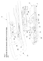
Fig. 1 illustrates a perspective view of a three-quarter rear perspective view of a stretcher for ambulance bearing the release device, object of the present invention; -
Fig. 2 illustrates a perspective view of the rear part of the stretcher offigure 1 , from which the patient surface has been removed, with the release device in non-operative position; -
Fig. 3 illustrates the same view offigure 2 , with the release device in operative position; -
Fig. 4 illustrates a top perspective view of the stretcher portion offigures 2 and3 , with the release device in non-operative position; -
Fig. 5 illustrates a bottom perspective view of the rear half of the stretcher, with the release device in operative position. - With reference to
figures 1 and5 , reference number 1 indicates a stretcher for ambulance, in particular of self-loading type, intended to receive a patient in laid-down position and to be subsequently locked to a fastening orsupport 2, integral with the walking surface of the ambulance itself (not illustrated for the sake of simplicity). Hereinbelow, reference will be made to front and rear parts of the stretcher 1, respectively for indicating the parts on which the head and the feed of the patient are set. The rear part of the stretcher 1 is that which, when loaded on the ambulance, is closer to the load door thereof. - The stretcher 1 comprises a
frame 3, made with a tubular structure, laterally provided withprotection sides 35 that can be pulled down and on which an anti-shock bed 4 is installed, provided with adjustments for tilting the head and legs of the patient. A mattress is installed on the bed, not shown in the figures in order to render the invention more visible. Theframe 3 is also provided, in proximity to the rear end thereof, with anextension 33, constituted by a shaped plate which is extended towards the lower part of theframe 3 itself. Fixed to the latter, and to other portions of theframe 3, are pairs ofloading wheels 34, intended to facilitate the introduction and extraction of the stretcher 1. - In the rear part thereof, the
frame 3 also forms agrip 31, like a grab bar, in order to allow an operator to easily handle the stretcher 1 during its movement. - From the lower part of the
frame 3, atrolley 5 is extended that can be lifted and retracted, provided withwheels 6 for allowing the stretcher 1 to be pushed between the ambulance and the patient pick-up or unloading site. For such purpose, thetrolley 5 is provided with suitable known mechanisms adapted to render the introduction thereof in the ambulance and the subsequent extraction thereof simple and not tiring for the operators. - The
fastening 2, in the non-limiting embodiment illustrated in the figures, is constituted by a plate having elongated form, against whosesurface 2a theloading wheels 34 of the stretcher 1 are intended to abut during the operations of introduction and extraction thereof into/from the ambulance. Thefastening 2 is also provided, in an entirely known manner, with devices suitable for facilitating the introduction and extraction of the stretcher 1, and with areleasable locking system 7, for locking the stretcher 1 itself in a transport position T. - The
locking system 7 is only partially illustrated in the figures, since its structure is not directly pertinent to the invention, and comprises afront locking device 7a, adapted to lock anaxle 61 of thewheels 6, and a rear locking device 7b, adapted to receive a fin 36 (seefigure 5 ) centrally mounted in the lower part of theshaped plate 33. Thelocking device 7 provides for an activation mechanism, controllable by means of a control device, both arranged within thesupport 2 and not visible in the figures. - The device for controlling the
locking device 7 is located within ahousing 8, accessible from the outside through alongitudinal slot 8a made on the surface of thesupport 2 itself. Also the control device is not directly illustrated in the figures, and is in substance constituted by a button actuatable via pressure. According to the conventional use modes, in order to carry out the release operation, the operator inserts a finger in theslot 8a, enters into thehousing 8 and presses the button of the control device, after which he/she frees the stretcher 1, dragging it towards the exit opening of the ambulance. - The
device 10 for the quick release of the stretcher 1 obtained according to the invention is fully comprised in the stretcher 1 itself, and comprises (seefigures 2 ,3 ,4 and5 ) adriving element 20, mounted in the lower part of theframe 2 in a manner such that, when the stretcher 1 is situated locked to thesupport 2 in the transport position T thereof, it is positioned immediately above theslot 8a of the housing 8 (figure 2 ). - The
driving element 20 comprises, in particular, acurved tube 21, centrally pivoted to theframe 3 by means of afork 29 fixed to theshaped plate 33 of theframe 3, and connected at an end thereof 21a tomovement transfer members 28. - In this manner, the
tube 21 can oscillate between a rest position R (figure 2 ), in which it is raised to the height of theplate 33 and does not interfere with the movements of the stretcher 1, and a release position S (figure 3 ), in which the opposite non-constrainedend 21b thereof is moved inside thehousing 8 in order to actuate the button of the control device, and thus free the stretcher 1 from thesupport 2. - At the
latter end 21b, thecurved tube 21 provides for acontact pin 22, which projects from the convex side of thetube 21 and is intended to engage the button of the control device during the operation of disengagement of the stretcher 1 from thesupport 2. - The
release device 10 also comprises control means 25 for thedriving element 20, arranged in proximity to thegrip 31 of the stretcher 1. In the preferred embodiment illustrated infigures 1 to 5 , the control means 25 comprise ahandle 26, arranged inside thesame grip 31, in a position immediately accessible by a hand of the operator and manually actuatable by the same. - The
handle 26 is slidably mounted on ablock 32 provided in theframe 3, with an end thereof connected to the abovementionedmovement transfer members 28. In substance, thehandle 26 is situated in the stable position thereof, corresponding to the rest position R of thecurved tube 21, in which it is distant from thegrip 31, and can be pulled by the operator in moving closer thereto, in order to actuate thetube 21 itself and bring it into the release position S. - The
handle 26 is maintained in rest position byelastic return members 27, constituted by a helical spring axially mounted on one branch of thehandle 26. - The abovementioned
movement transfer members 28, in the illustrated embodiment, are constituted by a suitably articulated lever, whose end arms are respectively connected to one arm of thehandle 26 and to one end of thetube 21. These are intended to transfer the action of the operator exerted on thehandle 26 to thetube 21, in order to bring it from the rest position R to the release position S and vice versa. - According to one embodiment of the invention, not illustrated but readily inferable, the
tube 21 can be actuated by an electromagnetic actuator, fixed to theplate 33 of theframe 3. In this case, the control means 25 comprise an electric button switch, and the transfer members 28 a simple pair of electric cables. In this case, naturally, a suitable rechargeable storage cell must be provided for supplying electrical energy to the electromagnetic actuator. - A further embodiment variant provide that the
tube 21 be actuated by a pneumatic actuator, it too fixed to theplate 33, fed by a suitable container of rechargeable compressed air. In this case, the control means 25 comprise a pneumatic switch, possibly drivable by a handle mechanism similar to that already described for the preferred embodiment of the invention. - The operation of the
release device 10 is simple and quite intuitive. With the stretcher outside the ambulance, or inside the in transport position T (figures 1 and2 ), thehandle 25 is situated in its stable position, and maintains thetube 21 in its rest position R by means of thelever 28. In such position, when the stretcher 1 is in transport position T, thetube 21 is situated distant from thehousing 8, and does not engage the button for activating the release mechanism of the stretcher 1. - When the operator wishes to extract the stretcher 1 from the ambulance, he/she grips the
handle 26 and pulls it towards himself/herself, moving closer to thegrip 31. In this manner, he/she operates on thelever 28 and imparts an oscillation to thetube 21, of about 90°, bringing it into release position (figure 3 ). - In this position, the
foot 22 mounted at theend 21b of thetube 21 engages the button for activating the release mechanism, and releases thefront axle 61 and thefin 36 of the stretcher 1 from therespective front 7a and rear 7b locking devices. - The operator can then begin to extract the stretcher 1 from the ambulance, and simultaneously releases the
handle 26, which is brought back into its stable position by thereturn spring 27. Thetube 21 is then brought back into the rest position R thereof by thelever 28. - A clear advantage that the invention allows obtaining is that of preventing the operator from inserting his/her hand between the stretcher 1 and the support, and his/her finger inside the
housing 8, in order to actuate the release button. - With this device, the operator can with two hands control the stretcher and thus prevents the operation - generally carried out without looking, or in any case in a rush situation due to emergency, and hence particularly risky - from damaging the operator itself.
- The operation of releasing the stretcher 1 carried out by means of the release device of the invention also allows, in any case, a time savings for the ambulance operators, which may prove precious in situations of particular urgency.
- In any case, it is intended that that described above is exemplifying and non-limiting, thus possible detail variations that may be necessary for technical and/or functional reasons are considered to fall within the same protective scope defined by the below-reported claims.
- In the embodiment, reference was made to a
device 10 for the release of stretchers, self-loading or otherwise; nevertheless, it is intended that thedevice 10, as stated from the start, is also applicable for operating autonomously and releasing patient transport wheelchairs; the same expedients are necessary for the positioning of therelease device 10, along with its drive and control means; in such a manner, also a wheelchair can be released from the fastening, controlling it with both hands. - In conclusion, the
device 10 for the release from at least onerelative fastening 2 of a stretcher 1 for ambulance or of a wheelchair comprises: - a driving
element 20, mounted in the lower part of theframe 3 of the wheelchair or of the stretcher, in proximity to ahousing 8 thereof and movable between a rest position R, in which said drivingelement 20 remains outside saidhousing 8, and a release position S, in which the same abovementioned drivingelement 20 fits into theabovementioned housing 8 in order to actuate the abovementioned control device; - control means 25 for said driving
element 20, arranged in proximity to thegrip 31 of the abovementioned stretcher 1, actuatable for moving said drivingelement 20 alternately between the rest R and release positions S.
Claims (7)
- Release device (10) for a stretcher (1) for ambulance or a patient transport wheelchair from at least one relative fastening (2); said fastening (2) integral with the floor or with a movable support surface of an ambulance for locking said stretcher (1) or said wheelchair in a transport position (T) during the transport of the same; said fastening (2) being provided with at least one releasable locking system (7) for said wheelchair or stretcher (1) and activation means for said at least one releasable locking system (7), controllable by means of a control device located in a housing (8) provided in said fastening (2); said quick release device (10) being characterized in that it comprises: a driving element (20), mounted on the frame (3) of the wheelchair or stretcher, in proximity to said housing (8) and movable between a rest position (R), in which said driving element (20) remains outside said housing (8), and a release position (S), in which the same said driving element (20) fits into said housing (8) for actuating said control device; control means (25) for said driving element (20), arranged in proximity to the grip (31) of said stretcher (1), actuatable for moving said driving element (20) alternately between the rest (R) and release (S) positions.
- Device according to claim 1, characterized in that said driving element (20) comprises a curved tube (21), centrally pivoted to said frame (3) and connected at one end (21a) to transfer members (28), the opposite non-constrained end (21b) of said tube (21) being provided for moving, with said tube (21) in release position (S), within said housing (8) in order to actuate said control device and thereby release the stretcher (1) or the wheelchair from the fastening (2).
- Device according to claim 2, characterized in that a contact pin (22) is provided at the non-constrained end (21b) of said curved tube (21), intended to engage said control device during the disengagement operation for the stretcher (1) or wheelchair.
- Device according to claim 1, characterized in that said control means (25) comprise a handle (26), slidably mounted on a block (32) provided in said frame (3), of the stretcher or patient transport wheelchair, with an end thereof connected to said transfer members (28) and manually actuatable between said rest (R) and release (S) positions, elastic return means (27) being provided for keeping said handle (26) in the rest position (R) in the absence of stress.
- Device according to claim 1 or claim 2, characterized in that said transfer members (28) consist of a lever, suitably articulated for transferring the action of said control means (25) to said driving means (20).
- Device according to claim 1 or claim 5, characterized in that said transfer members (28) comprise an electromagnetic actuator, mounted in the lower part of said frame (3), and in that said control means (25) comprise an electric button switch adapted to activate said electromagnetic actuator, an electric storage cell being provided in said stretcher (1) for supplying energy to said electromagnetic actuator.
- Device according to claim 1 or claim 5, characterized in that said transfer members (28) comprise a pneumatic actuator, mounted in the lower part of said frame (3), and in that said control means (25) comprise a pneumatic switch adapted to activate said pneumatic actuator, a container of compressed air being provided in said stretcher (1) or wheelchair in order to supply energy to said pneumatic actuator.
Applications Claiming Priority (1)
| Application Number | Priority Date | Filing Date | Title |
|---|---|---|---|
| ITUB2015A004188A ITUB20154188A1 (en) | 2015-10-07 | 2015-10-07 | DEVICE FOR THE ACTIVATION OF THE QUICK RELEASE OF AN AMBULANCE STRETCHER |
Publications (2)
| Publication Number | Publication Date |
|---|---|
| EP3153142A1 true EP3153142A1 (en) | 2017-04-12 |
| EP3153142B1 EP3153142B1 (en) | 2020-09-16 |
Family
ID=55237766
Family Applications (1)
| Application Number | Title | Priority Date | Filing Date |
|---|---|---|---|
| EP16192462.6A Active EP3153142B1 (en) | 2015-10-07 | 2016-10-05 | Device for activating the quick release of a stretcher for ambulance |
Country Status (3)
| Country | Link |
|---|---|
| EP (1) | EP3153142B1 (en) |
| ES (1) | ES2834061T3 (en) |
| IT (1) | ITUB20154188A1 (en) |
Citations (2)
| Publication number | Priority date | Publication date | Assignee | Title |
|---|---|---|---|---|
| US5913559A (en) * | 1997-03-19 | 1999-06-22 | Ferno-Washington, Inc. | Fastening track, cot transport vehicle adapted to secure the fastening track, and cot fastening system incorporating same |
| WO2004064698A2 (en) * | 2003-01-15 | 2004-08-05 | Stryker Corporation | Ambulance cot loading and unloading device |
-
2015
- 2015-10-07 IT ITUB2015A004188A patent/ITUB20154188A1/en unknown
-
2016
- 2016-10-05 EP EP16192462.6A patent/EP3153142B1/en active Active
- 2016-10-05 ES ES16192462T patent/ES2834061T3/en active Active
Patent Citations (2)
| Publication number | Priority date | Publication date | Assignee | Title |
|---|---|---|---|---|
| US5913559A (en) * | 1997-03-19 | 1999-06-22 | Ferno-Washington, Inc. | Fastening track, cot transport vehicle adapted to secure the fastening track, and cot fastening system incorporating same |
| WO2004064698A2 (en) * | 2003-01-15 | 2004-08-05 | Stryker Corporation | Ambulance cot loading and unloading device |
Also Published As
| Publication number | Publication date |
|---|---|
| ES2834061T3 (en) | 2021-06-16 |
| EP3153142B1 (en) | 2020-09-16 |
| ITUB20154188A1 (en) | 2017-04-07 |
Similar Documents
| Publication | Publication Date | Title |
|---|---|---|
| EP2228045B1 (en) | Ambulance cot loading and unloading device | |
| EP3643284B1 (en) | Care bed | |
| US8312578B2 (en) | Guide device for a motorized table comprising a unit that groups the table controls together | |
| RU2514744C2 (en) | Wheel-stretcher and system for patient transportation | |
| US7219754B2 (en) | Hospital bed power-assist | |
| EP2537499B1 (en) | Ambulance cot and loading and unloading system | |
| US12054188B2 (en) | System and method for electrically assisting in removal of deceased humans up and down stairs and into a vehicle | |
| CA2508394C (en) | Transport aid for wheeled support apparatus | |
| EP0064673B1 (en) | Apparatus for jacking up and supporting a structure | |
| US20100124476A1 (en) | Cylinder cart having a retention hook | |
| US5183235A (en) | Apparatus for aligning and releasing a two-part jack system | |
| CA2954158C (en) | Assistive device, and method of use | |
| US4960264A (en) | Alignment and release mechanism for two-part jack system | |
| JP4471744B2 (en) | Bed electric transfer device and drive control method thereof | |
| US12440397B2 (en) | System for loading/unloading an ambulance stretcher onto/from an ambulance | |
| WO2019223843A1 (en) | Robot with handcontrol for use in the rehabilitation of extremities | |
| EP3153142B1 (en) | Device for activating the quick release of a stretcher for ambulance | |
| JP2006000326A (en) | Electric assist conveyance equipment | |
| JP5755303B2 (en) | Transfer support device | |
| US20220008271A1 (en) | Device and method for reversibly connecting a rehabilitation mechanism to a bed, and method for operating a rehabilitation mechanism connected to a bed | |
| GB2302672A (en) | Ambulance trolley with powered scissor linkage | |
| US10973719B2 (en) | Lift mechanism | |
| JPH0450017B2 (en) | ||
| AU2012216245A1 (en) | Mortuary trolley | |
| WO2001049234A1 (en) | An examination table for diagnostics |
Legal Events
| Date | Code | Title | Description |
|---|---|---|---|
| PUAI | Public reference made under article 153(3) epc to a published international application that has entered the european phase |
Free format text: ORIGINAL CODE: 0009012 |
|
| STAA | Information on the status of an ep patent application or granted ep patent |
Free format text: STATUS: THE APPLICATION HAS BEEN PUBLISHED |
|
| AK | Designated contracting states |
Kind code of ref document: A1 Designated state(s): AL AT BE BG CH CY CZ DE DK EE ES FI FR GB GR HR HU IE IS IT LI LT LU LV MC MK MT NL NO PL PT RO RS SE SI SK SM TR |
|
| AX | Request for extension of the european patent |
Extension state: BA ME |
|
| STAA | Information on the status of an ep patent application or granted ep patent |
Free format text: STATUS: REQUEST FOR EXAMINATION WAS MADE |
|
| 17P | Request for examination filed |
Effective date: 20171012 |
|
| RAV | Requested validation state of the european patent: fee paid |
Extension state: MA Effective date: 20171012 |
|
| RBV | Designated contracting states (corrected) |
Designated state(s): AL AT BE BG CH CY CZ DE DK EE ES FI FR GB GR HR HU IE IS IT LI LT LU LV MC MK MT NL NO PL PT RO RS SE SI SK SM TR |
|
| RAP1 | Party data changed (applicant data changed or rights of an application transferred) |
Owner name: SPENCER ITALIA S.R.L. |
|
| STAA | Information on the status of an ep patent application or granted ep patent |
Free format text: STATUS: EXAMINATION IS IN PROGRESS |
|
| 17Q | First examination report despatched |
Effective date: 20180412 |
|
| REG | Reference to a national code |
Ref country code: DE Ref legal event code: R079 Ref document number: 602016044007 Country of ref document: DE Free format text: PREVIOUS MAIN CLASS: A61G0005100000 Ipc: A61G0003080000 |
|
| RIC1 | Information provided on ipc code assigned before grant |
Ipc: A61G 3/08 20060101AFI20200225BHEP |
|
| GRAP | Despatch of communication of intention to grant a patent |
Free format text: ORIGINAL CODE: EPIDOSNIGR1 |
|
| STAA | Information on the status of an ep patent application or granted ep patent |
Free format text: STATUS: GRANT OF PATENT IS INTENDED |
|
| INTG | Intention to grant announced |
Effective date: 20200407 |
|
| GRAS | Grant fee paid |
Free format text: ORIGINAL CODE: EPIDOSNIGR3 |
|
| GRAA | (expected) grant |
Free format text: ORIGINAL CODE: 0009210 |
|
| STAA | Information on the status of an ep patent application or granted ep patent |
Free format text: STATUS: THE PATENT HAS BEEN GRANTED |
|
| AK | Designated contracting states |
Kind code of ref document: B1 Designated state(s): AL AT BE BG CH CY CZ DE DK EE ES FI FR GB GR HR HU IE IS IT LI LT LU LV MC MK MT NL NO PL PT RO RS SE SI SK SM TR |
|
| REG | Reference to a national code |
Ref country code: GB Ref legal event code: FG4D |
|
| REG | Reference to a national code |
Ref country code: CH Ref legal event code: EP |
|
| REG | Reference to a national code |
Ref country code: DE Ref legal event code: R096 Ref document number: 602016044007 Country of ref document: DE |
|
| REG | Reference to a national code |
Ref country code: IE Ref legal event code: FG4D |
|
| REG | Reference to a national code |
Ref country code: AT Ref legal event code: REF Ref document number: 1313472 Country of ref document: AT Kind code of ref document: T Effective date: 20201015 |
|
| PG25 | Lapsed in a contracting state [announced via postgrant information from national office to epo] |
Ref country code: FI Free format text: LAPSE BECAUSE OF FAILURE TO SUBMIT A TRANSLATION OF THE DESCRIPTION OR TO PAY THE FEE WITHIN THE PRESCRIBED TIME-LIMIT Effective date: 20200916 Ref country code: NO Free format text: LAPSE BECAUSE OF FAILURE TO SUBMIT A TRANSLATION OF THE DESCRIPTION OR TO PAY THE FEE WITHIN THE PRESCRIBED TIME-LIMIT Effective date: 20201216 Ref country code: GR Free format text: LAPSE BECAUSE OF FAILURE TO SUBMIT A TRANSLATION OF THE DESCRIPTION OR TO PAY THE FEE WITHIN THE PRESCRIBED TIME-LIMIT Effective date: 20201217 Ref country code: SE Free format text: LAPSE BECAUSE OF FAILURE TO SUBMIT A TRANSLATION OF THE DESCRIPTION OR TO PAY THE FEE WITHIN THE PRESCRIBED TIME-LIMIT Effective date: 20200916 Ref country code: HR Free format text: LAPSE BECAUSE OF FAILURE TO SUBMIT A TRANSLATION OF THE DESCRIPTION OR TO PAY THE FEE WITHIN THE PRESCRIBED TIME-LIMIT Effective date: 20200916 Ref country code: BG Free format text: LAPSE BECAUSE OF FAILURE TO SUBMIT A TRANSLATION OF THE DESCRIPTION OR TO PAY THE FEE WITHIN THE PRESCRIBED TIME-LIMIT Effective date: 20201216 |
|
| REG | Reference to a national code |
Ref country code: AT Ref legal event code: MK05 Ref document number: 1313472 Country of ref document: AT Kind code of ref document: T Effective date: 20200916 |
|
| REG | Reference to a national code |
Ref country code: NL Ref legal event code: MP Effective date: 20200916 |
|
| PG25 | Lapsed in a contracting state [announced via postgrant information from national office to epo] |
Ref country code: LV Free format text: LAPSE BECAUSE OF FAILURE TO SUBMIT A TRANSLATION OF THE DESCRIPTION OR TO PAY THE FEE WITHIN THE PRESCRIBED TIME-LIMIT Effective date: 20200916 Ref country code: RS Free format text: LAPSE BECAUSE OF FAILURE TO SUBMIT A TRANSLATION OF THE DESCRIPTION OR TO PAY THE FEE WITHIN THE PRESCRIBED TIME-LIMIT Effective date: 20200916 |
|
| REG | Reference to a national code |
Ref country code: LT Ref legal event code: MG4D |
|
| PG25 | Lapsed in a contracting state [announced via postgrant information from national office to epo] |
Ref country code: EE Free format text: LAPSE BECAUSE OF FAILURE TO SUBMIT A TRANSLATION OF THE DESCRIPTION OR TO PAY THE FEE WITHIN THE PRESCRIBED TIME-LIMIT Effective date: 20200916 Ref country code: SM Free format text: LAPSE BECAUSE OF FAILURE TO SUBMIT A TRANSLATION OF THE DESCRIPTION OR TO PAY THE FEE WITHIN THE PRESCRIBED TIME-LIMIT Effective date: 20200916 Ref country code: RO Free format text: LAPSE BECAUSE OF FAILURE TO SUBMIT A TRANSLATION OF THE DESCRIPTION OR TO PAY THE FEE WITHIN THE PRESCRIBED TIME-LIMIT Effective date: 20200916 Ref country code: PT Free format text: LAPSE BECAUSE OF FAILURE TO SUBMIT A TRANSLATION OF THE DESCRIPTION OR TO PAY THE FEE WITHIN THE PRESCRIBED TIME-LIMIT Effective date: 20210118 Ref country code: CZ Free format text: LAPSE BECAUSE OF FAILURE TO SUBMIT A TRANSLATION OF THE DESCRIPTION OR TO PAY THE FEE WITHIN THE PRESCRIBED TIME-LIMIT Effective date: 20200916 Ref country code: LT Free format text: LAPSE BECAUSE OF FAILURE TO SUBMIT A TRANSLATION OF THE DESCRIPTION OR TO PAY THE FEE WITHIN THE PRESCRIBED TIME-LIMIT Effective date: 20200916 Ref country code: NL Free format text: LAPSE BECAUSE OF FAILURE TO SUBMIT A TRANSLATION OF THE DESCRIPTION OR TO PAY THE FEE WITHIN THE PRESCRIBED TIME-LIMIT Effective date: 20200916 |
|
| PG25 | Lapsed in a contracting state [announced via postgrant information from national office to epo] |
Ref country code: AT Free format text: LAPSE BECAUSE OF FAILURE TO SUBMIT A TRANSLATION OF THE DESCRIPTION OR TO PAY THE FEE WITHIN THE PRESCRIBED TIME-LIMIT Effective date: 20200916 Ref country code: AL Free format text: LAPSE BECAUSE OF FAILURE TO SUBMIT A TRANSLATION OF THE DESCRIPTION OR TO PAY THE FEE WITHIN THE PRESCRIBED TIME-LIMIT Effective date: 20200916 Ref country code: PL Free format text: LAPSE BECAUSE OF FAILURE TO SUBMIT A TRANSLATION OF THE DESCRIPTION OR TO PAY THE FEE WITHIN THE PRESCRIBED TIME-LIMIT Effective date: 20200916 Ref country code: IS Free format text: LAPSE BECAUSE OF FAILURE TO SUBMIT A TRANSLATION OF THE DESCRIPTION OR TO PAY THE FEE WITHIN THE PRESCRIBED TIME-LIMIT Effective date: 20210116 |
|
| REG | Reference to a national code |
Ref country code: CH Ref legal event code: PL |
|
| VS25 | Lapsed in a validation state [announced via postgrant information from nat. office to epo] |
Ref country code: MA Free format text: LAPSE BECAUSE OF FAILURE TO SUBMIT A TRANSLATION OF THE DESCRIPTION OR TO PAY THE FEE WITHIN THE PRESCRIBED TIME-LIMIT Effective date: 20200916 |
|
| REG | Reference to a national code |
Ref country code: ES Ref legal event code: FG2A Ref document number: 2834061 Country of ref document: ES Kind code of ref document: T3 Effective date: 20210616 |
|
| REG | Reference to a national code |
Ref country code: DE Ref legal event code: R097 Ref document number: 602016044007 Country of ref document: DE |
|
| PG25 | Lapsed in a contracting state [announced via postgrant information from national office to epo] |
Ref country code: MC Free format text: LAPSE BECAUSE OF FAILURE TO SUBMIT A TRANSLATION OF THE DESCRIPTION OR TO PAY THE FEE WITHIN THE PRESCRIBED TIME-LIMIT Effective date: 20200916 Ref country code: LU Free format text: LAPSE BECAUSE OF NON-PAYMENT OF DUE FEES Effective date: 20201005 Ref country code: SK Free format text: LAPSE BECAUSE OF FAILURE TO SUBMIT A TRANSLATION OF THE DESCRIPTION OR TO PAY THE FEE WITHIN THE PRESCRIBED TIME-LIMIT Effective date: 20200916 |
|
| REG | Reference to a national code |
Ref country code: BE Ref legal event code: MM Effective date: 20201031 |
|
| PLBE | No opposition filed within time limit |
Free format text: ORIGINAL CODE: 0009261 |
|
| STAA | Information on the status of an ep patent application or granted ep patent |
Free format text: STATUS: NO OPPOSITION FILED WITHIN TIME LIMIT |
|
| 26N | No opposition filed |
Effective date: 20210617 |
|
| PG25 | Lapsed in a contracting state [announced via postgrant information from national office to epo] |
Ref country code: LI Free format text: LAPSE BECAUSE OF NON-PAYMENT OF DUE FEES Effective date: 20201031 Ref country code: SI Free format text: LAPSE BECAUSE OF FAILURE TO SUBMIT A TRANSLATION OF THE DESCRIPTION OR TO PAY THE FEE WITHIN THE PRESCRIBED TIME-LIMIT Effective date: 20200916 Ref country code: CH Free format text: LAPSE BECAUSE OF NON-PAYMENT OF DUE FEES Effective date: 20201031 Ref country code: BE Free format text: LAPSE BECAUSE OF NON-PAYMENT OF DUE FEES Effective date: 20201031 Ref country code: DK Free format text: LAPSE BECAUSE OF FAILURE TO SUBMIT A TRANSLATION OF THE DESCRIPTION OR TO PAY THE FEE WITHIN THE PRESCRIBED TIME-LIMIT Effective date: 20200916 |
|
| PG25 | Lapsed in a contracting state [announced via postgrant information from national office to epo] |
Ref country code: IE Free format text: LAPSE BECAUSE OF NON-PAYMENT OF DUE FEES Effective date: 20201005 |
|
| PG25 | Lapsed in a contracting state [announced via postgrant information from national office to epo] |
Ref country code: TR Free format text: LAPSE BECAUSE OF FAILURE TO SUBMIT A TRANSLATION OF THE DESCRIPTION OR TO PAY THE FEE WITHIN THE PRESCRIBED TIME-LIMIT Effective date: 20200916 Ref country code: MT Free format text: LAPSE BECAUSE OF FAILURE TO SUBMIT A TRANSLATION OF THE DESCRIPTION OR TO PAY THE FEE WITHIN THE PRESCRIBED TIME-LIMIT Effective date: 20200916 Ref country code: CY Free format text: LAPSE BECAUSE OF FAILURE TO SUBMIT A TRANSLATION OF THE DESCRIPTION OR TO PAY THE FEE WITHIN THE PRESCRIBED TIME-LIMIT Effective date: 20200916 |
|
| PG25 | Lapsed in a contracting state [announced via postgrant information from national office to epo] |
Ref country code: MK Free format text: LAPSE BECAUSE OF FAILURE TO SUBMIT A TRANSLATION OF THE DESCRIPTION OR TO PAY THE FEE WITHIN THE PRESCRIBED TIME-LIMIT Effective date: 20200916 |
|
| PGFP | Annual fee paid to national office [announced via postgrant information from national office to epo] |
Ref country code: FR Payment date: 20221031 Year of fee payment: 7 |
|
| PGFP | Annual fee paid to national office [announced via postgrant information from national office to epo] |
Ref country code: IT Payment date: 20221028 Year of fee payment: 7 Ref country code: GB Payment date: 20221020 Year of fee payment: 7 Ref country code: ES Payment date: 20221222 Year of fee payment: 7 Ref country code: DE Payment date: 20221019 Year of fee payment: 7 |
|
| REG | Reference to a national code |
Ref country code: DE Ref legal event code: R119 Ref document number: 602016044007 Country of ref document: DE |
|
| GBPC | Gb: european patent ceased through non-payment of renewal fee |
Effective date: 20231005 |
|
| PG25 | Lapsed in a contracting state [announced via postgrant information from national office to epo] |
Ref country code: GB Free format text: LAPSE BECAUSE OF NON-PAYMENT OF DUE FEES Effective date: 20231005 |
|
| PG25 | Lapsed in a contracting state [announced via postgrant information from national office to epo] |
Ref country code: GB Free format text: LAPSE BECAUSE OF NON-PAYMENT OF DUE FEES Effective date: 20231005 Ref country code: FR Free format text: LAPSE BECAUSE OF NON-PAYMENT OF DUE FEES Effective date: 20231031 Ref country code: DE Free format text: LAPSE BECAUSE OF NON-PAYMENT OF DUE FEES Effective date: 20240501 |
|
| REG | Reference to a national code |
Ref country code: ES Ref legal event code: FD2A Effective date: 20241126 |
|
| PG25 | Lapsed in a contracting state [announced via postgrant information from national office to epo] |
Ref country code: IT Free format text: LAPSE BECAUSE OF NON-PAYMENT OF DUE FEES Effective date: 20231005 |
|
| PG25 | Lapsed in a contracting state [announced via postgrant information from national office to epo] |
Ref country code: IT Free format text: LAPSE BECAUSE OF NON-PAYMENT OF DUE FEES Effective date: 20231005 |
|
| PG25 | Lapsed in a contracting state [announced via postgrant information from national office to epo] |
Ref country code: ES Free format text: LAPSE BECAUSE OF NON-PAYMENT OF DUE FEES Effective date: 20231006 |
|
| PG25 | Lapsed in a contracting state [announced via postgrant information from national office to epo] |
Ref country code: ES Free format text: LAPSE BECAUSE OF NON-PAYMENT OF DUE FEES Effective date: 20231006 |