EP3152798B1 - Conical monopole antenna - Google Patents
Conical monopole antenna Download PDFInfo
- Publication number
- EP3152798B1 EP3152798B1 EP15732759.4A EP15732759A EP3152798B1 EP 3152798 B1 EP3152798 B1 EP 3152798B1 EP 15732759 A EP15732759 A EP 15732759A EP 3152798 B1 EP3152798 B1 EP 3152798B1
- Authority
- EP
- European Patent Office
- Prior art keywords
- conical
- ground plate
- monopole antenna
- cylindrical member
- antenna according
- Prior art date
- Legal status (The legal status is an assumption and is not a legal conclusion. Google has not performed a legal analysis and makes no representation as to the accuracy of the status listed.)
- Active
Links
Images

Classifications
-
- H—ELECTRICITY
- H01—ELECTRIC ELEMENTS
- H01Q—ANTENNAS, i.e. RADIO AERIALS
- H01Q9/00—Electrically-short antennas having dimensions not more than twice the operating wavelength and consisting of conductive active radiating elements
- H01Q9/04—Resonant antennas
- H01Q9/30—Resonant antennas with feed to end of elongated active element, e.g. unipole
- H01Q9/40—Element having extended radiating surface
-
- H—ELECTRICITY
- H01—ELECTRIC ELEMENTS
- H01Q—ANTENNAS, i.e. RADIO AERIALS
- H01Q5/00—Arrangements for simultaneous operation of antennas on two or more different wavebands, e.g. dual-band or multi-band arrangements
- H01Q5/20—Arrangements for simultaneous operation of antennas on two or more different wavebands, e.g. dual-band or multi-band arrangements characterised by the operating wavebands
- H01Q5/25—Ultra-wideband [UWB] systems, e.g. multiple resonance systems; Pulse systems
-
- H—ELECTRICITY
- H01—ELECTRIC ELEMENTS
- H01Q—ANTENNAS, i.e. RADIO AERIALS
- H01Q9/00—Electrically-short antennas having dimensions not more than twice the operating wavelength and consisting of conductive active radiating elements
- H01Q9/04—Resonant antennas
- H01Q9/30—Resonant antennas with feed to end of elongated active element, e.g. unipole
- H01Q9/32—Vertical arrangement of element
- H01Q9/36—Vertical arrangement of element with top loading
-
- H—ELECTRICITY
- H01—ELECTRIC ELEMENTS
- H01Q—ANTENNAS, i.e. RADIO AERIALS
- H01Q9/00—Electrically-short antennas having dimensions not more than twice the operating wavelength and consisting of conductive active radiating elements
- H01Q9/04—Resonant antennas
- H01Q9/30—Resonant antennas with feed to end of elongated active element, e.g. unipole
- H01Q9/32—Vertical arrangement of element
- H01Q9/38—Vertical arrangement of element with counterpoise
Definitions
- the present invention relates to a conical monopole antenna according to the preamble of the appended independent claim.
- Wideband antennas are well known in the prior art and are widely used in various communications systems.
- An example of such a wideband antenna is a conical monopole antenna, also known as a monocone antenna that provides a low VSWR (Voltage Standing Wave Ratio) over a relatively wide frequency band.
- VSWR Voltage Standing Wave Ratio
- a conventional conical monopole antenna comprises a ground plate and a conical member, which are arranged at a small distance from each other such that the apex of the conical member is pointing toward the ground plate and the axis of the conical member is perpendicular to the plane of the ground plate.
- the lower cut-off frequency of the conventional conical monopole antenna is determined by the diameter of the base of the conical member and the height of the conical member.
- the higher cut-off frequency of the conventional conical monopole antenna is provided by making the diameter at the apex of the conical member to correspond to that associated with the highest frequency of interest.
- the conventional conical monopole antenna comprises a coaxial feeder with an inner conductor connected to the apex of the conical member, and an outer conductor connected to the ground plate.
- the coaxial feeder extends outwardly from the ground plate on a side thereof opposite the apex of the conical member.
- a problem associated with the conventional conical monopole antenna is that the VSWR of the antenna is too high for many applications. The problem arises especially at low frequencies where the VSWR typically increases rapidly below a certain cut-off frequency. This cut-off frequency can be decreased by increasing the size of the conical member. This, however, increases the VSWR at high frequencies. It also increases the size of the antenna.
- Z Monopole antennas that have a conical part and a cylindrical part are for example disclosed in US2724052 , EP2154752 and US2006/0012528
- the conical monopole antenna according to the invention is characterised by what is presented in the characterising part of the appended independent claim.
- Advantageous embodiments of the invention are described in the dependent claims.
- a typical conical monopole antenna according to the invention comprises a first ground plate having a first and a second side, and a conical member having an apex and a base, the apex of the conical member being directed towards the first side of the first ground plate and the axis of the conical member being perpendicular to the plane of the first ground plate.
- the typical conical monopole antenna according to the invention further comprises a cylindrical member having a first and a second end, the first end of the cylindrical member being directed towards the base of the conical member and the axis of the cylindrical member being perpendicular to the plane of the first ground plate, and a plurality of connecting members connecting the cylindrical member to the conical member in such a manner that the cylindrical member and the conical member are at a distance from each other.
- the first ground plate and the conical member form the basic structure of the conical monopole antenna.
- the apex of the conical member is pointing toward and arranged at a distance from the first side of the first ground plate.
- the conical member is a right circular cone that is arranged with respect to the first ground plate such that its (longitudinal) axis is perpendicular to the plane of the first ground plate.
- the apex of the conical member is connected to an inner conductor of a coaxial connector, and the first ground plate is connected to an outer conductor of the coaxial connector.
- the coaxial connector may be mounted to the first ground plate.
- a coaxial cable can be connected to the coaxial connector through the second side of the first ground plate.
- the first ground plate and the conical member are preferably made of an electrically conductive material.
- the first ground plate and the conical member can be made, for example, of a metal, such as copper, aluminium or brass, or of an electrically conductive polymer or plastic.
- the first ground plate can have various shapes and dimensions depending on the requirements of the antenna.
- the first ground plate is a disc, the diameter of which is chosen according to the diameter of the base of the conical member.
- the axis of the conical member is preferably arranged to pass through the centre of the disc.
- the thickness of the first ground plate can be chosen according to the height of the cylindrical member; as the height of the cylindrical member is increased also the thickness of the first ground plate should be increased.
- the first ground plate is preferably solid.
- the diameter of the first ground plate can be, for example, 80-100 mm, and the thickness of the first ground plate can be, for example, 15-25 mm.
- the conical member can be solid or hollow.
- a hollow conical member can be made of a metal sheet that is cut into a suitable shape and then rolled into a cone. The dimensions of the conical member are chosen according to the requirements of the antenna.
- the diameter of the base of the conical member and the height of the conical member affect the lower cut-off frequency of the conical monopole antenna.
- the diameter of the base of the conical member can be, for example, 80-100 mm, and the height of the conical member can be, for example, 60-80 mm.
- the opening angle of the conical member can be, for example, 30-100 degrees, 40-90 degrees, 50-80 degrees or 60-70 degrees.
- the cylindrical member is connected to the conical member with the plurality of connecting members in such a manner that the cylindrical member and the conical member are separated from each other by a distance, which is preferably at least 1 mm. In other words, there is a gap between the cylindrical member and the conical member.
- the cylindrical member is galvanically connected to the conical member through the connecting members.
- the cylindrical member and the conical member are also capacitively connected to one another.
- the cylindrical member is preferably arranged concentric with the conical member, so that the axis of the cylindrical member is congruent with the axis of the conical member.
- the connecting members define with the cylindrical member and the conical member a plurality of openings.
- Each connecting member is preferably connected to an outer edge of the first end of the cylindrical member, and to an outer edge of the base of the conical member.
- the connecting members are symmetrically arranged so that the distances between adjacent connecting members are essentially equal.
- the cylindrical member and the connecting members are preferably made of an electrically conductive material.
- the cylindrical member and the connecting members can be made, for example, of a metal, such as copper, aluminium or brass, or of an electrically conductive polymer or plastic.
- the cylindrical member can be solid or hollow.
- a hollow cylindrical member can be made of a metal sheet that is cut into a suitable shape and then rolled into a cylinder.
- the diameter of the cylindrical member is equal to the diameter of the base of the conical member.
- the diameter of the cylindrical member can be, for example, 80-100 mm, and the height of the cylindrical member can be, for example, 15-25 mm.
- the connecting members are preferably bars or wires, the first ends of which are connected to the first end of the cylindrical member, and the second ends of which are connected to the base of the conical member.
- the cylindrical member which is galvanically connected to the conical member with the connecting members, extends the length of the conical monopole antenna without increasing its diameter. This decreases the lower cut-off frequency of the conical monopole antenna, and as a result the VSWR performance of the conical monopole antenna is improved at low frequencies.
- the cylindrical member is also capacitively connected to the conical member since the cylindrical member is arranged at a distance from the conical member. Due to this capacitive connection, the higher cut-off frequency of the conical monopole antenna is increased, and thus the VSWR performance of the conical monopole antenna is also improved at high frequencies.
- the air gap between the conical member and the cylindrical member improves the radiation pattern performance at frequencies over 2 GHz and especially in the range of 5 to 18 GHz.
- the VSWR performance of the conical monopole antenna remains good at high frequencies.
- a construction without an air gap would have a usable radiation pattern performance only up to 2 GHz resulting in negative gains for 2.4 GHz and 5.8 GHz WiFi bands.
- the conical monopole antenna according to the invention provides a very low VSWR over a wide frequency band. With the conical monopole antenna according to the invention, the average wideband VSWR performance in the 1 GHz to 18 GHz communication band can be as low as 1.2:1. On specific communication bands the VSWR can even be 1.1:1.
- the diameter of the cylindrical member is equal to the diameter of the base of the conical member. This is an optimal choice from the point of view of the VSWR performance.
- the diameter of the first ground plate is at most equal to the diameter of the base of the conical member. A larger diameter of the first ground plate would result in the radiation pattern of the antenna being lifted at high frequencies. A larger diameter of the first ground plate would also degrade the VSWR performance at high frequencies.
- the distance between the cylindrical member and the conical member is 1-5 mm.
- the optimal distance depends on the dimensions of the cylindrical member and the conical member. In many applications, a good choice for the distance between the cylindrical member and the conical member from the point of view of the VSWR performance is 2-3 mm.
- the number of the plurality of connecting members is 3-10.
- the number of the connecting members is 6-8.
- the width of each connecting member can be, for example, 1-10 mm, preferably 2-8 mm, and more preferably 4-6 mm.
- the optimal number and the size of the connecting members depend on the size of the cylindrical member.
- the conical monopole antenna comprises a second ground plate having a first and a second side, the first side of the second ground plate being attached to the second side of the first ground plate, and the diameter of the second ground plate being larger than the diameter of the first ground plate.
- the second ground plate improves the VSWR performance of the conical monopole antenna at low frequencies.
- the first and the second ground plate form a staggered structure that allows decreasing the lower cut-off frequency without degrading the VSWR performance at high frequencies.
- the staggered (tapered) structure of the first and the second ground plate reduces the electrical diameter of the required ground area of the conical monopole antenna having the cylindrical member connected to the conical member.
- the staggered ground plate structure allows a direct installation of the conical monopole antenna on a large metal surface without degrading effects to the radiation pattern and the VSWR performance.
- a single ground plate causes the radiation pattern to tilt upwards resulting in a negative gain in the horizon.
- the staggered ground plate structure together with the air gap between the conical and the cylindrical member improves the antenna gain and the radiation pattern even more towards the horizon.
- the second ground plate has also other advantages. It can function as a mechanical support for a radome. It also enables the conical monopole antenna to be installed on a wide conductive surface, such as a metal roof of a building, a vehicle or a vessel, without performance degradation of the antenna.
- the second ground plate may also function at the same time as a mounting plate comprising holes for mounting screws.
- the second ground plate is preferably made of an electrically conductive material.
- the second ground plate can be made, for example, of a metal, such as copper, aluminium or brass, or of an electrically conductive polymer or plastic.
- the second ground plate can have various shapes and dimensions depending on the requirements of the antenna. However, preferably the second ground plate is a disc, the diameter of which can be chosen according to the height of the conical member and/or the cylindrical member. The diameter of the second ground plate can be, for example, 130-150 mm, and the thickness of the second ground plate can be, for example, 4-10 mm.
- the second ground plate is preferably solid.
- the conical monopole antenna may comprise more than two ground plates, each having a different diameter.
- the ground plates are arranged in a staggered manner so that the uppermost ground plate has the smallest diameter and the lowermost ground plate has the largest diameter.
- the first and/or the second ground plate comprises a plurality of metal layers arranged one upon the other.
- the parasitic capacitance due to the layered structure enables to achieve the same performance with thinner ground plates.
- the metal layers can be arranged directly one upon the other, or using electrically non-conductive layers between the metal layers.
- the thickness of the metal layers can be, for example, less than 1 mm, 0.5-1 mm, 1-2 mm or 2-4 mm.
- the first and the second ground plate are made from a single block.
- the conical monopole antenna comprises a tubular member arranged partly inside the conical member, the longitudinal axis of the tubular member being perpendicular to the plane of the first ground plate.
- the tubular member is used to extend the frequency band of the conical monopole antenna to a desired low frequency communication band, such as VHF or TETRA.
- the length of the tubular member is chosen to correspond to the desired communication band.
- the first end of the tubular member that is inside the conical member can be galvanically or capacitively connected to the conical member.
- the tubular member is preferably made of an electrically conductive material.
- the tubular member can be made of various materials, for example of a metal, such as copper, aluminium or brass, or of an electrically conductive polymer or plastic.
- the tubular member can be solid or hollow.
- the tubular member is a tube that is arranged concentric with the conical member, so that the longitudinal axis of the tube is congruent with the axis of the conical member.
- the length of the tubular member can be, for example, 100-400 mm, and the diameter of the tubular member can be, for example, 5-30 mm.
- the tubular member is capacitively connected to the conical member. Capacitive connection between the tubular member and the conical member enables to use a shorter tubular member compared to a situation where the tubular member is galvanically connected to the conical member.
- the tubular member can be attached to the conical member using a support that is made of electrically non-conductive material. Alternatively, the tubular member can be attached to a radome.
- the tubular member is made of carbon fibre.
- An advantage of the carbon fibre is that it widens the narrowband response produced by the tubular member compared to other materials such as metals.
- the conical monopole antenna comprises at least one grounding wire connected between the conical member and the first ground plate. Because of the grounding wire, a static discharge can be prevented in the conical monopole antenna, and thus the sensitivity is improved.
- the grounding wire also acts as a lightning protection for a communication system and it conducts EMC disturbances to a ground potential when the ground plate(s) is(are) electrically conductive and installed on a larger electrically conductive surface or when another grounding structure is used.
- the first end of the grounding wire is connected to the base of the conical member, and the second end of the grounding wire is connected to the first side of the first ground plate.
- the grounding wires can be symmetrically distributed around the conical member. This improves the VSWR performance when only one ground plate is used.
- the conical monopole antenna comprises a coaxial connector having an inner and an outer conductor, the inner conductor being connected to the conical member, and the outer conductor being connected to the first ground plate.
- the inner conductor is connected to the apex of the conical member.
- the coaxial connector is mounted to the first ground plate.
- a coaxial cable can be connected to the coaxial connector through the second side of the first ground plate and possibly also through the second ground plate.
- the conical member and/or the cylindrical member and/or the tubular member are hollow.
- the conical member and/or the cylindrical member and/or the tubular member comprise an electrically non-conductive core covered with an electrically conductive layer.
- the inner part is made of electrically non-conductive material
- the outer part is made of electrically conductive material.
- the electrically non-conductive material can be, for example, PTFE (Teflon), glass fibre, ASA or some other RF neutral material.
- a conical monopole antenna comprises a first ground plate having a first and a second side, and a conical member having an apex and a base, the apex of the conical member being directed towards the first side of the first ground plate and the axis of the conical member being perpendicular to the plane of the first ground plate.
- the conical monopole antenna according to this embodiment further comprises a second ground plate having a first and a second side, the first side of the second ground plate being attached to the second side of the first ground plate, and the diameter of the second ground plate being larger than the diameter of the first ground plate.
- a conical monopole antenna comprises a first ground plate having a first and a second side, and a conical member having an apex and a base, the apex of the conical member being directed towards the first side of the first ground plate and the axis of the conical member being perpendicular to the plane of the first ground plate.
- the conical monopole antenna according to this embodiment further comprises a tubular member arranged partly inside the conical member, the longitudinal axis of the tubular member being perpendicular to the plane of the first ground plate.
- the conical monopole antenna comprises a second cylindrical member having a first and a second end, the first end of the second cylindrical member being directed towards the second end of the first cylindrical member and the axis of the second cylindrical member being perpendicular to the plane of the first ground plate, and a plurality of second connecting members connecting the second cylindrical member to the first cylindrical member in such a manner that the first and the second cylindrical member are at a distance from each other.
- An advantage of the second cylindrical member is that it further decreases the lower cut-off frequency of the conical monopole antenna.
- the use of the second cylindrical member electrically shortens the antenna compared to a construction with only one long cylindrical member.
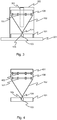
- Fig. 1 illustrates a conical monopole antenna according to a first embodiment of the invention.
- the conical monopole antenna comprises a first ground plate 101 and a conical member 102, the apex of which is directed towards and arranged at a distance from the first side of the first ground plate 101.
- the conical member 102 is arranged with respect to the first ground plate 101 such that its axis is perpendicular to the plane of the first ground plate 101 and passes through the centre of the first ground plate 101.
- the diameter of the first ground plate 101 is equal to the diameter of the base of the conical member 102.
- the conical monopole antenna comprises a coaxial connector 103 that is mounted to the first ground plate 101.
- An inner conductor 104 of the coaxial connector 103 is connected to the apex of the conical member 102, and an outer conductor 105 of the coaxial connector 103 is connected to the first ground plate 101.
- a coaxial cable (not shown in fig. 1 ) can be connected to the coaxial connector 103 through the second side of the first ground plate 101.
- the conical monopole antenna comprises a cylindrical member 106 that is connected to the conical member 102 with a plurality of connecting members 107 such that the cylindrical member 106 and the conical member 102 are at a distance from each other.
- the first end of the cylindrical member 106 is facing the base of the conical member 102 and the axis of the cylindrical member 106 is arranged perpendicular to the plane of the first ground plate 101.
- the cylindrical member 106 is arranged concentric with the conical member 102, so that the axis of the cylindrical member 106 is congruent with the axis of the conical member 102.
- the diameter of the cylindrical member 106 is equal to the diameter of the base of the conical member 102.
- Each connecting member 107 is connected to an outer edge of the first end of the cylindrical member 106 and to an outer edge of the base of the conical member 102.
- the connecting members 107 are symmetrically arranged on the circumference of the base of the conical member 102 and the first end of the cylindrical member 106 so that the distances between adjacent connecting members 107 are essentially equal.
- the cylindrical member 106 which is galvanically connected to the conical member 102 through the connecting members 107, extends the length of the conical monopole antenna without increasing its diameter. This decreases the lower cut-off frequency of the antenna, and as a result the VSWR performance of the antenna is improved at low frequencies.
- the cylindrical member 106 and the conical member 102 are also capacitively connected to one another, because the cylindrical member 106 and the conical member 102 are separated by a distance. Due to this capacitive connection, the higher cut-off frequency of the antenna is increased, and thus the VSWR performance of the antenna is also improved at high frequencies.
- Fig. 2 illustrates a conical monopole antenna according to a second embodiment of the invention, which differs from the embodiment of fig. 1 in that the conical monopole antenna also comprises a second ground plate 201 and a grounding wire 202.
- the first side of the second ground plate 201 is attached to the second side of the first ground plate 101.
- the diameter of the second ground plate 201 is larger than the diameter of the first ground plate 101, whereby the first and the second ground plate 101, 201 form a staggered structure that allows decreasing the lower cut-off frequency of the antenna without degrading the VSWR performance at high frequencies.
- the grounding wire 202 is connected between the conical member 102 and the first ground plate 101 to prevent a static discharge in the conical monopole antenna.
- the first end of the grounding wire 202 is connected to the base of the conical member 102, and the second end of the grounding wire 202 is connected to the first side of the first ground plate 101.
- Fig. 3 illustrates a conical monopole antenna according to a third embodiment of the invention, which differs from the embodiment of fig. 1 in that the conical monopole antenna also comprises a second ground plate 201, a tubular member 301 that is used to extend the frequency band of the conical monopole antenna to a desired low frequency communication band, and a radome 302 for protecting the conical monopole antenna.
- the second end of the tubular member 301 is attached to the radome 302 in such a manner that the tubular member 301 passes through the cylindrical member 106 inside the conical member 102.
- the first end of the tubular member 301 is separated by a distance from the conical member 102 so that the tubular member 301 is capacitively connected to the conical member 102.
- the longitudinal axis of the tubular member 301 is perpendicular to the plane of the first ground plate 101.
- Fig. 4 illustrates a conical monopole antenna according to a fourth embodiment of the invention, which differs from the embodiment of fig. 1 in that the conical monopole antenna also comprises a second cylindrical member 401 and a plurality of second connecting members 402.
- the second cylindrical member 401 is connected to the first cylindrical member 106 with the second connecting members 402 such that the first and the second cylindrical member 106, 401 are at a distance from each other.
- the second connecting members 402 are symmetrically arranged on the circumference of the first end of the second cylindrical member 401 and the second end of the first cylindrical member 106 so that the distances between adjacent connecting members 402 are essentially equal.
- the first end of the second cylindrical member 401 is facing the second end of the first cylindrical member 106.
- the second cylindrical member 401 is arranged concentric with the first cylindrical member 106, so that the axis of the second cylindrical member 401 is congruent with the axis of the first cylindrical member 106.
- the diameter of the second cylindrical member 401 is equal to the diameter of the first cylindrical member 106.
Landscapes
- Details Of Aerials (AREA)
Description
- The present invention relates to a conical monopole antenna according to the preamble of the appended independent claim.
- Wideband antennas are well known in the prior art and are widely used in various communications systems. An example of such a wideband antenna is a conical monopole antenna, also known as a monocone antenna that provides a low VSWR (Voltage Standing Wave Ratio) over a relatively wide frequency band.
- A conventional conical monopole antenna comprises a ground plate and a conical member, which are arranged at a small distance from each other such that the apex of the conical member is pointing toward the ground plate and the axis of the conical member is perpendicular to the plane of the ground plate. The lower cut-off frequency of the conventional conical monopole antenna is determined by the diameter of the base of the conical member and the height of the conical member. The higher cut-off frequency of the conventional conical monopole antenna is provided by making the diameter at the apex of the conical member to correspond to that associated with the highest frequency of interest. The conventional conical monopole antenna comprises a coaxial feeder with an inner conductor connected to the apex of the conical member, and an outer conductor connected to the ground plate. The coaxial feeder extends outwardly from the ground plate on a side thereof opposite the apex of the conical member.
- A problem associated with the conventional conical monopole antenna is that the VSWR of the antenna is too high for many applications. The problem arises especially at low frequencies where the VSWR typically increases rapidly below a certain cut-off frequency. This cut-off frequency can be decreased by increasing the size of the conical member. This, however, increases the VSWR at high frequencies. It also increases the size of the antenna. Z Monopole antennas that have a conical part and a cylindrical part are for example disclosed in
US2724052 ,EP2154752 andUS2006/0012528 - It is the main objective of the present invention to reduce or even eliminate prior art problems presented above.
- It is an objective of the present invention to provide a conical monopole antenna that provides a very low VSWR over a wide frequency band. Especially, it is an objective of the invention to improve the VSWR performance of a conical monopole antenna at low and high frequencies. In other words, it is an objective of the invention to decrease the lower cut-off frequency and to increase the higher cut-off frequency of a conical monopole antenna.
- It is also an objective of the present invention to provide a conical monopole antenna that is small-sized and easy to manufacture, and has a good performance in a wide frequency band.
- In order to realise the above-mentioned objectives, the conical monopole antenna according to the invention is characterised by what is presented in the characterising part of the appended independent claim. Advantageous embodiments of the invention are described in the dependent claims.
- A typical conical monopole antenna according to the invention comprises a first ground plate having a first and a second side, and a conical member having an apex and a base, the apex of the conical member being directed towards the first side of the first ground plate and the axis of the conical member being perpendicular to the plane of the first ground plate. The typical conical monopole antenna according to the invention further comprises a cylindrical member having a first and a second end, the first end of the cylindrical member being directed towards the base of the conical member and the axis of the cylindrical member being perpendicular to the plane of the first ground plate, and a plurality of connecting members connecting the cylindrical member to the conical member in such a manner that the cylindrical member and the conical member are at a distance from each other.
- The first ground plate and the conical member form the basic structure of the conical monopole antenna. The apex of the conical member is pointing toward and arranged at a distance from the first side of the first ground plate. The conical member is a right circular cone that is arranged with respect to the first ground plate such that its (longitudinal) axis is perpendicular to the plane of the first ground plate. The apex of the conical member is connected to an inner conductor of a coaxial connector, and the first ground plate is connected to an outer conductor of the coaxial connector. The coaxial connector may be mounted to the first ground plate. A coaxial cable can be connected to the coaxial connector through the second side of the first ground plate.
- The first ground plate and the conical member are preferably made of an electrically conductive material. The first ground plate and the conical member can be made, for example, of a metal, such as copper, aluminium or brass, or of an electrically conductive polymer or plastic. The first ground plate can have various shapes and dimensions depending on the requirements of the antenna. However, preferably the first ground plate is a disc, the diameter of which is chosen according to the diameter of the base of the conical member. When the first ground plate is a disc, the axis of the conical member is preferably arranged to pass through the centre of the disc. The thickness of the first ground plate can be chosen according to the height of the cylindrical member; as the height of the cylindrical member is increased also the thickness of the first ground plate should be increased. The first ground plate is preferably solid. The diameter of the first ground plate can be, for example, 80-100 mm, and the thickness of the first ground plate can be, for example, 15-25 mm. The conical member can be solid or hollow. A hollow conical member can be made of a metal sheet that is cut into a suitable shape and then rolled into a cone. The dimensions of the conical member are chosen according to the requirements of the antenna. The diameter of the base of the conical member and the height of the conical member affect the lower cut-off frequency of the conical monopole antenna. The diameter of the base of the conical member can be, for example, 80-100 mm, and the height of the conical member can be, for example, 60-80 mm. The opening angle of the conical member can be, for example, 30-100 degrees, 40-90 degrees, 50-80 degrees or 60-70 degrees.
- The cylindrical member is connected to the conical member with the plurality of connecting members in such a manner that the cylindrical member and the conical member are separated from each other by a distance, which is preferably at least 1 mm. In other words, there is a gap between the cylindrical member and the conical member. The cylindrical member is galvanically connected to the conical member through the connecting members. On the other hand, since the cylindrical member and the conical member are separated by a distance from each other, the cylindrical member and the conical member are also capacitively connected to one another. The cylindrical member is preferably arranged concentric with the conical member, so that the axis of the cylindrical member is congruent with the axis of the conical member.
- The connecting members define with the cylindrical member and the conical member a plurality of openings. Each connecting member is preferably connected to an outer edge of the first end of the cylindrical member, and to an outer edge of the base of the conical member. Preferably, the connecting members are symmetrically arranged so that the distances between adjacent connecting members are essentially equal.
- The cylindrical member and the connecting members are preferably made of an electrically conductive material. The cylindrical member and the connecting members can be made, for example, of a metal, such as copper, aluminium or brass, or of an electrically conductive polymer or plastic. The cylindrical member can be solid or hollow. A hollow cylindrical member can be made of a metal sheet that is cut into a suitable shape and then rolled into a cylinder. Preferably, the diameter of the cylindrical member is equal to the diameter of the base of the conical member. The diameter of the cylindrical member can be, for example, 80-100 mm, and the height of the cylindrical member can be, for example, 15-25 mm. The connecting members are preferably bars or wires, the first ends of which are connected to the first end of the cylindrical member, and the second ends of which are connected to the base of the conical member. By optimising the size and the amount of the connecting members the resonant frequencies can be kept out from the operating frequencies of the conical monopole antenna.
- The cylindrical member, which is galvanically connected to the conical member with the connecting members, extends the length of the conical monopole antenna without increasing its diameter. This decreases the lower cut-off frequency of the conical monopole antenna, and as a result the VSWR performance of the conical monopole antenna is improved at low frequencies. In the present invention, the cylindrical member is also capacitively connected to the conical member since the cylindrical member is arranged at a distance from the conical member. Due to this capacitive connection, the higher cut-off frequency of the conical monopole antenna is increased, and thus the VSWR performance of the conical monopole antenna is also improved at high frequencies. The air gap between the conical member and the cylindrical member improves the radiation pattern performance at frequencies over 2 GHz and especially in the range of 5 to 18 GHz. The VSWR performance of the conical monopole antenna remains good at high frequencies. A construction without an air gap would have a usable radiation pattern performance only up to 2 GHz resulting in negative gains for 2.4 GHz and 5.8 GHz WiFi bands. The conical monopole antenna according to the invention provides a very low VSWR over a wide frequency band. With the conical monopole antenna according to the invention, the average wideband VSWR performance in the 1 GHz to 18 GHz communication band can be as low as 1.2:1. On specific communication bands the VSWR can even be 1.1:1.
- According to an embodiment of the invention the diameter of the cylindrical member is equal to the diameter of the base of the conical member. This is an optimal choice from the point of view of the VSWR performance.
- According to an embodiment of the invention the diameter of the first ground plate is at most equal to the diameter of the base of the conical member. A larger diameter of the first ground plate would result in the radiation pattern of the antenna being lifted at high frequencies. A larger diameter of the first ground plate would also degrade the VSWR performance at high frequencies.
- According to an embodiment of the invention the distance between the cylindrical member and the conical member is 1-5 mm. The optimal distance depends on the dimensions of the cylindrical member and the conical member. In many applications, a good choice for the distance between the cylindrical member and the conical member from the point of view of the VSWR performance is 2-3 mm.
- According to an embodiment of the invention the number of the plurality of connecting members is 3-10. Preferably, the number of the connecting members is 6-8. The width of each connecting member can be, for example, 1-10 mm, preferably 2-8 mm, and more preferably 4-6 mm. The optimal number and the size of the connecting members depend on the size of the cylindrical member.
- According to an embodiment of the invention the conical monopole antenna comprises a second ground plate having a first and a second side, the first side of the second ground plate being attached to the second side of the first ground plate, and the diameter of the second ground plate being larger than the diameter of the first ground plate. The second ground plate, the diameter of which is larger than the diameter of the first ground plate, improves the VSWR performance of the conical monopole antenna at low frequencies. The first and the second ground plate form a staggered structure that allows decreasing the lower cut-off frequency without degrading the VSWR performance at high frequencies. The features of this embodiment can also be applied with the same advantages in a conical monopole antenna that does not comprise a cylindrical member and a plurality of connecting members.
- The staggered (tapered) structure of the first and the second ground plate reduces the electrical diameter of the required ground area of the conical monopole antenna having the cylindrical member connected to the conical member. The staggered ground plate structure allows a direct installation of the conical monopole antenna on a large metal surface without degrading effects to the radiation pattern and the VSWR performance. A single ground plate causes the radiation pattern to tilt upwards resulting in a negative gain in the horizon. The staggered ground plate structure together with the air gap between the conical and the cylindrical member improves the antenna gain and the radiation pattern even more towards the horizon.
- The second ground plate has also other advantages. It can function as a mechanical support for a radome. It also enables the conical monopole antenna to be installed on a wide conductive surface, such as a metal roof of a building, a vehicle or a vessel, without performance degradation of the antenna. The second ground plate may also function at the same time as a mounting plate comprising holes for mounting screws.
- The second ground plate is preferably made of an electrically conductive material. The second ground plate can be made, for example, of a metal, such as copper, aluminium or brass, or of an electrically conductive polymer or plastic. The second ground plate can have various shapes and dimensions depending on the requirements of the antenna. However, preferably the second ground plate is a disc, the diameter of which can be chosen according to the height of the conical member and/or the cylindrical member. The diameter of the second ground plate can be, for example, 130-150 mm, and the thickness of the second ground plate can be, for example, 4-10 mm. The second ground plate is preferably solid.
- The conical monopole antenna may comprise more than two ground plates, each having a different diameter. The ground plates are arranged in a staggered manner so that the uppermost ground plate has the smallest diameter and the lowermost ground plate has the largest diameter.
- According to an embodiment of the invention the first and/or the second ground plate comprises a plurality of metal layers arranged one upon the other. The parasitic capacitance due to the layered structure enables to achieve the same performance with thinner ground plates. The metal layers can be arranged directly one upon the other, or using electrically non-conductive layers between the metal layers. The thickness of the metal layers can be, for example, less than 1 mm, 0.5-1 mm, 1-2 mm or 2-4 mm.
- According to an embodiment of the invention the first and the second ground plate are made from a single block.
- According to an embodiment of the invention the conical monopole antenna comprises a tubular member arranged partly inside the conical member, the longitudinal axis of the tubular member being perpendicular to the plane of the first ground plate. The tubular member is used to extend the frequency band of the conical monopole antenna to a desired low frequency communication band, such as VHF or TETRA. The length of the tubular member is chosen to correspond to the desired communication band. The first end of the tubular member that is inside the conical member can be galvanically or capacitively connected to the conical member. The features of this embodiment can also be applied with the same advantages in a conical monopole antenna that does not comprise a cylindrical member and a plurality of connecting members.
- The tubular member is preferably made of an electrically conductive material. The tubular member can be made of various materials, for example of a metal, such as copper, aluminium or brass, or of an electrically conductive polymer or plastic. The tubular member can be solid or hollow. Preferably, the tubular member is a tube that is arranged concentric with the conical member, so that the longitudinal axis of the tube is congruent with the axis of the conical member. The length of the tubular member can be, for example, 100-400 mm, and the diameter of the tubular member can be, for example, 5-30 mm.
- According to an embodiment of the invention the tubular member is capacitively connected to the conical member. Capacitive connection between the tubular member and the conical member enables to use a shorter tubular member compared to a situation where the tubular member is galvanically connected to the conical member. The tubular member can be attached to the conical member using a support that is made of electrically non-conductive material. Alternatively, the tubular member can be attached to a radome.
- According to an embodiment of the invention the tubular member is made of carbon fibre. An advantage of the carbon fibre is that it widens the narrowband response produced by the tubular member compared to other materials such as metals.
- According to an embodiment of the invention the conical monopole antenna comprises at least one grounding wire connected between the conical member and the first ground plate. Because of the grounding wire, a static discharge can be prevented in the conical monopole antenna, and thus the sensitivity is improved. The grounding wire also acts as a lightning protection for a communication system and it conducts EMC disturbances to a ground potential when the ground plate(s) is(are) electrically conductive and installed on a larger electrically conductive surface or when another grounding structure is used. Preferably, the first end of the grounding wire is connected to the base of the conical member, and the second end of the grounding wire is connected to the first side of the first ground plate. The grounding wires can be symmetrically distributed around the conical member. This improves the VSWR performance when only one ground plate is used.
- According to an embodiment of the invention the conical monopole antenna comprises a coaxial connector having an inner and an outer conductor, the inner conductor being connected to the conical member, and the outer conductor being connected to the first ground plate. The inner conductor is connected to the apex of the conical member. The coaxial connector is mounted to the first ground plate. A coaxial cable can be connected to the coaxial connector through the second side of the first ground plate and possibly also through the second ground plate.
- According to an embodiment of the invention the conical member and/or the cylindrical member and/or the tubular member are hollow.
- According to an embodiment of the invention the conical member and/or the cylindrical member and/or the tubular member comprise an electrically non-conductive core covered with an electrically conductive layer. In other words, the inner part is made of electrically non-conductive material, whereas the outer part is made of electrically conductive material. An advantage of this structure is that it is easy and cheap to manufacture. The electrically non-conductive material can be, for example, PTFE (Teflon), glass fibre, ASA or some other RF neutral material.
- According to an embodiment a conical monopole antenna is provided that comprises a first ground plate having a first and a second side, and a conical member having an apex and a base, the apex of the conical member being directed towards the first side of the first ground plate and the axis of the conical member being perpendicular to the plane of the first ground plate. The conical monopole antenna according to this embodiment further comprises a second ground plate having a first and a second side, the first side of the second ground plate being attached to the second side of the first ground plate, and the diameter of the second ground plate being larger than the diameter of the first ground plate.
- According to an embodiment a conical monopole antenna is provided that comprises a first ground plate having a first and a second side, and a conical member having an apex and a base, the apex of the conical member being directed towards the first side of the first ground plate and the axis of the conical member being perpendicular to the plane of the first ground plate. The conical monopole antenna according to this embodiment further comprises a tubular member arranged partly inside the conical member, the longitudinal axis of the tubular member being perpendicular to the plane of the first ground plate.
- According to an embodiment of the invention the conical monopole antenna comprises a second cylindrical member having a first and a second end, the first end of the second cylindrical member being directed towards the second end of the first cylindrical member and the axis of the second cylindrical member being perpendicular to the plane of the first ground plate, and a plurality of second connecting members connecting the second cylindrical member to the first cylindrical member in such a manner that the first and the second cylindrical member are at a distance from each other. An advantage of the second cylindrical member is that it further decreases the lower cut-off frequency of the conical monopole antenna. Furthermore, the use of the second cylindrical member electrically shortens the antenna compared to a construction with only one long cylindrical member.
- The exemplary embodiments of the invention presented in this text are not interpreted to pose limitations to the applicability of the appended claims. The verb "to comprise" is used in this text as an open limitation that does not exclude the existence of also unrecited features. The features recited in the dependent claims are mutually freely combinable unless otherwise explicitly stated.
-
- Fig. 1
- illustrates a conical monopole antenna according to a first embodiment of the invention,
- fig. 2
- illustrates a conical monopole antenna according to a second embodiment of the invention,
- fig. 3
- illustrates a conical monopole antenna according to a third embodiment of the invention, and
- fig. 4
- illustrates a conical monopole antenna according to a fourth embodiment of the invention.
- The same reference signs are used of the same or like components in different embodiments.
-
Fig. 1 illustrates a conical monopole antenna according to a first embodiment of the invention. The conical monopole antenna comprises afirst ground plate 101 and aconical member 102, the apex of which is directed towards and arranged at a distance from the first side of thefirst ground plate 101. Theconical member 102 is arranged with respect to thefirst ground plate 101 such that its axis is perpendicular to the plane of thefirst ground plate 101 and passes through the centre of thefirst ground plate 101. The diameter of thefirst ground plate 101 is equal to the diameter of the base of theconical member 102. - The conical monopole antenna comprises a
coaxial connector 103 that is mounted to thefirst ground plate 101. Aninner conductor 104 of thecoaxial connector 103 is connected to the apex of theconical member 102, and anouter conductor 105 of thecoaxial connector 103 is connected to thefirst ground plate 101. A coaxial cable (not shown infig. 1 ) can be connected to thecoaxial connector 103 through the second side of thefirst ground plate 101. - The conical monopole antenna comprises a
cylindrical member 106 that is connected to theconical member 102 with a plurality of connectingmembers 107 such that thecylindrical member 106 and theconical member 102 are at a distance from each other. The first end of thecylindrical member 106 is facing the base of theconical member 102 and the axis of thecylindrical member 106 is arranged perpendicular to the plane of thefirst ground plate 101. Thecylindrical member 106 is arranged concentric with theconical member 102, so that the axis of thecylindrical member 106 is congruent with the axis of theconical member 102. The diameter of thecylindrical member 106 is equal to the diameter of the base of theconical member 102. - Each connecting
member 107 is connected to an outer edge of the first end of thecylindrical member 106 and to an outer edge of the base of theconical member 102. The connectingmembers 107 are symmetrically arranged on the circumference of the base of theconical member 102 and the first end of thecylindrical member 106 so that the distances between adjacent connectingmembers 107 are essentially equal. - The
cylindrical member 106, which is galvanically connected to theconical member 102 through the connectingmembers 107, extends the length of the conical monopole antenna without increasing its diameter. This decreases the lower cut-off frequency of the antenna, and as a result the VSWR performance of the antenna is improved at low frequencies. Thecylindrical member 106 and theconical member 102 are also capacitively connected to one another, because thecylindrical member 106 and theconical member 102 are separated by a distance. Due to this capacitive connection, the higher cut-off frequency of the antenna is increased, and thus the VSWR performance of the antenna is also improved at high frequencies. -
Fig. 2 illustrates a conical monopole antenna according to a second embodiment of the invention, which differs from the embodiment offig. 1 in that the conical monopole antenna also comprises asecond ground plate 201 and agrounding wire 202. - The first side of the
second ground plate 201 is attached to the second side of thefirst ground plate 101. The diameter of thesecond ground plate 201 is larger than the diameter of thefirst ground plate 101, whereby the first and thesecond ground plate - The
grounding wire 202 is connected between theconical member 102 and thefirst ground plate 101 to prevent a static discharge in the conical monopole antenna. The first end of thegrounding wire 202 is connected to the base of theconical member 102, and the second end of thegrounding wire 202 is connected to the first side of thefirst ground plate 101. -
Fig. 3 illustrates a conical monopole antenna according to a third embodiment of the invention, which differs from the embodiment offig. 1 in that the conical monopole antenna also comprises asecond ground plate 201, atubular member 301 that is used to extend the frequency band of the conical monopole antenna to a desired low frequency communication band, and aradome 302 for protecting the conical monopole antenna. - The second end of the
tubular member 301 is attached to theradome 302 in such a manner that thetubular member 301 passes through thecylindrical member 106 inside theconical member 102. The first end of thetubular member 301 is separated by a distance from theconical member 102 so that thetubular member 301 is capacitively connected to theconical member 102. The longitudinal axis of thetubular member 301 is perpendicular to the plane of thefirst ground plate 101. -
Fig. 4 illustrates a conical monopole antenna according to a fourth embodiment of the invention, which differs from the embodiment offig. 1 in that the conical monopole antenna also comprises a secondcylindrical member 401 and a plurality of second connectingmembers 402. The secondcylindrical member 401 is connected to the firstcylindrical member 106 with the second connectingmembers 402 such that the first and the secondcylindrical member members 402 are symmetrically arranged on the circumference of the first end of the secondcylindrical member 401 and the second end of the firstcylindrical member 106 so that the distances between adjacent connectingmembers 402 are essentially equal. - The first end of the second
cylindrical member 401 is facing the second end of the firstcylindrical member 106. The secondcylindrical member 401 is arranged concentric with the firstcylindrical member 106, so that the axis of the secondcylindrical member 401 is congruent with the axis of the firstcylindrical member 106. The diameter of the secondcylindrical member 401 is equal to the diameter of the firstcylindrical member 106. - Only advantageous exemplary embodiments of the invention are described in the figures. It is clear to a person skilled in the art that the invention is not restricted only to the examples presented above, but the invention may vary within the limits of the claims presented hereafter. Some possible embodiments of the invention are described in the dependent claims, and they are not to be considered to restrict the scope of protection of the invention as such.
Claims (15)
- A conical monopole antenna, comprising:- a first ground plate (101) having a first and a second side, and- a conical member (102) having an apex and a base, the apex of the conical member (102) being directed towards the first side of the first ground plate (101) and the axis of the conical member (102) being perpendicular to the plane of the first ground plate (101), and- a cylindrical member (106) having a first and a second end, the first end of the cylindrical member (106) being directed towards the base of the conical member (102) and the axis of the cylindrical member (106) being perpendicular to the plane of the first ground plate (101),characterised in that the conical monopole antenna comprises:- a plurality of connecting members (107) connecting the cylindrical member (106) to the conical member (102) in such a manner that the cylindrical member (106) and the conical member (102) are at a distance from each other, the connecting members (107) defining with the cylindrical member (106) and the conical member (102) a plurality of openings.
- The conical monopole antenna according to claim 1, characterised in that the diameter of the cylindrical member (106) is equal to the diameter of the base of the conical member (102).
- The conical monopole antenna according to claim 1 or 2, characterised in that the diameter of the first ground plate (101) is at most equal to the diameter of the base of the conical member (102).
- The conical monopole antenna according to any of the preceding claims, characterised in that the distance between the cylindrical member (106) and the conical member (102) is 1-5 mm.
- The conical monopole antenna according to any of the preceding claims, characterised in that the number of the plurality of connecting members (107) is 3-10.
- The conical monopole antenna according to any of the preceding claims, characterised in that the conical monopole antenna comprises a second ground plate (201) having a first and a second side, the first side of the second ground plate (201) being attached to the second side of the first ground plate (101), and the diameter of the second ground plate (201) being larger than the diameter of the first ground plate (101).
- The conical monopole antenna according to claim 6, characterised in that the first and/or the second ground plate (101, 201) comprises a plurality of metal layers arranged one upon the other.
- The conical monopole antenna according to claim 6, characterised in that the first and the second ground plate (101, 201) are made from a single block.
- The conical monopole antenna according to any of the preceding claims, characterised in that the conical monopole antenna comprises a tubular member (301) arranged partly inside the conical member (102), the longitudinal axis of the tubular member (301) being perpendicular to the plane of the first ground plate (101).
- The conical monopole antenna according to claim 9, characterised in that the tubular member (301) is capacitively connected to the conical member (102).
- The conical monopole antenna according to claim 9 or 10, characterised in that the tubular member (301) is made of carbon fibre.
- The conical monopole antenna according to any of the preceding claims, characterised in that the conical monopole antenna comprises at least one grounding wire (202) connected between the conical member (102) and the first ground plate (101).
- The conical monopole antenna according to any of the preceding claims, characterised in that the conical monopole antenna comprises a coaxial connector (103) having an inner and an outer conductor (104, 105), the inner conductor (104) being connected to the conical member (102), and the outer conductor (105) being connected to the first ground plate (101).
- The conical monopole antenna according to any of the preceding claims, characterised in that the conical member (102) and/or the cylindrical member (106) and/or the tubular member (301) are hollow.
- The conical monopole antenna according to any of the preceding claims, characterised in that the conical member (102) and/or the cylindrical member (106) and/or the tubular member (301) comprise an electrically non-conductive core covered with an electrically conductive layer.
Applications Claiming Priority (2)
| Application Number | Priority Date | Filing Date | Title |
|---|---|---|---|
| FI20145528 | 2014-06-09 | ||
| PCT/FI2015/050404 WO2015189471A1 (en) | 2014-06-09 | 2015-06-09 | Conical monopole antenna |
Publications (2)
| Publication Number | Publication Date |
|---|---|
| EP3152798A1 EP3152798A1 (en) | 2017-04-12 |
| EP3152798B1 true EP3152798B1 (en) | 2020-08-19 |
Family
ID=53496732
Family Applications (1)
| Application Number | Title | Priority Date | Filing Date |
|---|---|---|---|
| EP15732759.4A Active EP3152798B1 (en) | 2014-06-09 | 2015-06-09 | Conical monopole antenna |
Country Status (3)
| Country | Link |
|---|---|
| EP (1) | EP3152798B1 (en) |
| DK (1) | DK3152798T3 (en) |
| WO (1) | WO2015189471A1 (en) |
Families Citing this family (6)
| Publication number | Priority date | Publication date | Assignee | Title |
|---|---|---|---|---|
| DE102017101677A1 (en) * | 2017-01-27 | 2018-08-02 | Kathrein-Werke Kg | Broadband omnidirectional antenna |
| WO2021049672A1 (en) * | 2019-09-09 | 2021-03-18 | 엘지전자 주식회사 | Electronic device having antenna |
| WO2021054494A1 (en) * | 2019-09-19 | 2021-03-25 | 엘지전자 주식회사 | Broadband antenna mounted on vehicle |
| CN114843759B (en) * | 2022-03-22 | 2023-04-14 | 宁波大学 | A Monopole Water Antenna |
| DE102023206601A1 (en) | 2023-07-12 | 2025-01-16 | Vega Grieshaber Kg | measuring device with cylindrical monopole antenna |
| US20250273868A1 (en) * | 2024-02-28 | 2025-08-28 | Massive Light Llc | Reconfigurable reflector for biconical antenna |
Family Cites Families (5)
| Publication number | Priority date | Publication date | Assignee | Title |
|---|---|---|---|---|
| US2724052A (en) * | 1950-11-30 | 1955-11-15 | Douglas Aircraft Co Inc | Radio antennas |
| JP4475583B2 (en) * | 2004-07-13 | 2010-06-09 | 株式会社リコー | Discone antenna and information communication equipment using the discone antenna |
| US7973731B2 (en) * | 2008-05-23 | 2011-07-05 | Harris Corporation | Folded conical antenna and associated methods |
| US7999757B2 (en) * | 2008-08-06 | 2011-08-16 | Pctel, Inc. | Multi-band ceiling antenna |
| CN203312446U (en) * | 2012-10-30 | 2013-11-27 | 盖尔创尼克斯有限公司 | Compact broadband omnidirectional antenna used in indoor/outdoor applications |
-
2015
- 2015-06-09 EP EP15732759.4A patent/EP3152798B1/en active Active
- 2015-06-09 DK DK15732759.4T patent/DK3152798T3/en active
- 2015-06-09 WO PCT/FI2015/050404 patent/WO2015189471A1/en not_active Ceased
Non-Patent Citations (1)
| Title |
|---|
| None * |
Also Published As
| Publication number | Publication date |
|---|---|
| EP3152798A1 (en) | 2017-04-12 |
| WO2015189471A1 (en) | 2015-12-17 |
| DK3152798T3 (en) | 2020-10-19 |
Similar Documents
| Publication | Publication Date | Title |
|---|---|---|
| US20060284779A1 (en) | Inverted feed discone antenna and related methods | |
| EP3152798A1 (en) | Conical monopole antenna | |
| EP1939981B1 (en) | Antenna apparatus | |
| US7495627B2 (en) | Broadband planar dipole antenna structure and associated methods | |
| US8314744B2 (en) | Biconical dipole antenna including choke assemblies and related methods | |
| US10411357B1 (en) | Ultra-wideband unipole antenna | |
| US10483640B1 (en) | Omnidirectional ultra-wideband antenna | |
| US8654025B1 (en) | Broadband, small profile, omnidirectional antenna with extended low frequency range | |
| CN201601217U (en) | Dual-wideband omnidirectional ceiling antenna | |
| US20150070234A1 (en) | High-Band Radiators In Moats For Basestation Antennas | |
| KR101826315B1 (en) | Curved shape conformal antenna | |
| WO2004068630A2 (en) | Compact low rcs ultra-wide bandwidth conical monopole antenna | |
| CN104885299A (en) | Compact, broadband, omnidirectional antenna for indoor/outdoor applications | |
| US9531082B2 (en) | Antenna arrangement | |
| US9692136B2 (en) | Monocone antenna | |
| US8339324B1 (en) | Wideband biconical antenna with helix feed for an above-mounted antenna | |
| US11682841B2 (en) | Communications device with helically wound conductive strip and related antenna devices and methods | |
| WO2012144247A1 (en) | Wide band antenna | |
| CN106848577A (en) | A kind of logarithm period monopole antenna | |
| US10431893B1 (en) | Omnidirectional multiband antenna | |
| US7450081B1 (en) | Compact low frequency radio antenna | |
| US6342855B1 (en) | Mobile radiotelephony planar antenna | |
| US20160043464A1 (en) | Ground Plane Meandering in Z Direction for Spiral Antenna | |
| US9077076B2 (en) | Compact, ultra-broadband antenna with doughnut-like radiation pattern | |
| US9831554B2 (en) | Antenna apparatus |
Legal Events
| Date | Code | Title | Description |
|---|---|---|---|
| STAA | Information on the status of an ep patent application or granted ep patent |
Free format text: STATUS: THE INTERNATIONAL PUBLICATION HAS BEEN MADE |
|
| PUAI | Public reference made under article 153(3) epc to a published international application that has entered the european phase |
Free format text: ORIGINAL CODE: 0009012 |
|
| STAA | Information on the status of an ep patent application or granted ep patent |
Free format text: STATUS: REQUEST FOR EXAMINATION WAS MADE |
|
| 17P | Request for examination filed |
Effective date: 20161229 |
|
| AK | Designated contracting states |
Kind code of ref document: A1 Designated state(s): AL AT BE BG CH CY CZ DE DK EE ES FI FR GB GR HR HU IE IS IT LI LT LU LV MC MK MT NL NO PL PT RO RS SE SI SK SM TR |
|
| AX | Request for extension of the european patent |
Extension state: BA ME |
|
| DAV | Request for validation of the european patent (deleted) | ||
| DAX | Request for extension of the european patent (deleted) | ||
| GRAP | Despatch of communication of intention to grant a patent |
Free format text: ORIGINAL CODE: EPIDOSNIGR1 |
|
| STAA | Information on the status of an ep patent application or granted ep patent |
Free format text: STATUS: GRANT OF PATENT IS INTENDED |
|
| INTG | Intention to grant announced |
Effective date: 20200415 |
|
| GRAS | Grant fee paid |
Free format text: ORIGINAL CODE: EPIDOSNIGR3 |
|
| GRAA | (expected) grant |
Free format text: ORIGINAL CODE: 0009210 |
|
| STAA | Information on the status of an ep patent application or granted ep patent |
Free format text: STATUS: THE PATENT HAS BEEN GRANTED |
|
| AK | Designated contracting states |
Kind code of ref document: B1 Designated state(s): AL AT BE BG CH CY CZ DE DK EE ES FI FR GB GR HR HU IE IS IT LI LT LU LV MC MK MT NL NO PL PT RO RS SE SI SK SM TR |
|
| REG | Reference to a national code |
Ref country code: CH Ref legal event code: EP |
|
| REG | Reference to a national code |
Ref country code: DE Ref legal event code: R096 Ref document number: 602015057680 Country of ref document: DE |
|
| REG | Reference to a national code |
Ref country code: AT Ref legal event code: REF Ref document number: 1305009 Country of ref document: AT Kind code of ref document: T Effective date: 20200915 |
|
| REG | Reference to a national code |
Ref country code: IE Ref legal event code: FG4D |
|
| REG | Reference to a national code |
Ref country code: DK Ref legal event code: T3 Effective date: 20201016 |
|
| REG | Reference to a national code |
Ref country code: FI Ref legal event code: FGE |
|
| REG | Reference to a national code |
Ref country code: NO Ref legal event code: T2 Effective date: 20200819 |
|
| REG | Reference to a national code |
Ref country code: LT Ref legal event code: MG4D |
|
| REG | Reference to a national code |
Ref country code: NL Ref legal event code: MP Effective date: 20200819 |
|
| PG25 | Lapsed in a contracting state [announced via postgrant information from national office to epo] |
Ref country code: BG Free format text: LAPSE BECAUSE OF FAILURE TO SUBMIT A TRANSLATION OF THE DESCRIPTION OR TO PAY THE FEE WITHIN THE PRESCRIBED TIME-LIMIT Effective date: 20201119 Ref country code: PT Free format text: LAPSE BECAUSE OF FAILURE TO SUBMIT A TRANSLATION OF THE DESCRIPTION OR TO PAY THE FEE WITHIN THE PRESCRIBED TIME-LIMIT Effective date: 20201221 Ref country code: GR Free format text: LAPSE BECAUSE OF FAILURE TO SUBMIT A TRANSLATION OF THE DESCRIPTION OR TO PAY THE FEE WITHIN THE PRESCRIBED TIME-LIMIT Effective date: 20201120 Ref country code: LT Free format text: LAPSE BECAUSE OF FAILURE TO SUBMIT A TRANSLATION OF THE DESCRIPTION OR TO PAY THE FEE WITHIN THE PRESCRIBED TIME-LIMIT Effective date: 20200819 Ref country code: SE Free format text: LAPSE BECAUSE OF FAILURE TO SUBMIT A TRANSLATION OF THE DESCRIPTION OR TO PAY THE FEE WITHIN THE PRESCRIBED TIME-LIMIT Effective date: 20200819 Ref country code: HR Free format text: LAPSE BECAUSE OF FAILURE TO SUBMIT A TRANSLATION OF THE DESCRIPTION OR TO PAY THE FEE WITHIN THE PRESCRIBED TIME-LIMIT Effective date: 20200819 |
|
| REG | Reference to a national code |
Ref country code: AT Ref legal event code: MK05 Ref document number: 1305009 Country of ref document: AT Kind code of ref document: T Effective date: 20200819 |
|
| PG25 | Lapsed in a contracting state [announced via postgrant information from national office to epo] |
Ref country code: LV Free format text: LAPSE BECAUSE OF FAILURE TO SUBMIT A TRANSLATION OF THE DESCRIPTION OR TO PAY THE FEE WITHIN THE PRESCRIBED TIME-LIMIT Effective date: 20200819 Ref country code: PL Free format text: LAPSE BECAUSE OF FAILURE TO SUBMIT A TRANSLATION OF THE DESCRIPTION OR TO PAY THE FEE WITHIN THE PRESCRIBED TIME-LIMIT Effective date: 20200819 Ref country code: RS Free format text: LAPSE BECAUSE OF FAILURE TO SUBMIT A TRANSLATION OF THE DESCRIPTION OR TO PAY THE FEE WITHIN THE PRESCRIBED TIME-LIMIT Effective date: 20200819 Ref country code: NL Free format text: LAPSE BECAUSE OF FAILURE TO SUBMIT A TRANSLATION OF THE DESCRIPTION OR TO PAY THE FEE WITHIN THE PRESCRIBED TIME-LIMIT Effective date: 20200819 Ref country code: IS Free format text: LAPSE BECAUSE OF FAILURE TO SUBMIT A TRANSLATION OF THE DESCRIPTION OR TO PAY THE FEE WITHIN THE PRESCRIBED TIME-LIMIT Effective date: 20201219 |
|
| PG25 | Lapsed in a contracting state [announced via postgrant information from national office to epo] |
Ref country code: CZ Free format text: LAPSE BECAUSE OF FAILURE TO SUBMIT A TRANSLATION OF THE DESCRIPTION OR TO PAY THE FEE WITHIN THE PRESCRIBED TIME-LIMIT Effective date: 20200819 Ref country code: EE Free format text: LAPSE BECAUSE OF FAILURE TO SUBMIT A TRANSLATION OF THE DESCRIPTION OR TO PAY THE FEE WITHIN THE PRESCRIBED TIME-LIMIT Effective date: 20200819 Ref country code: SM Free format text: LAPSE BECAUSE OF FAILURE TO SUBMIT A TRANSLATION OF THE DESCRIPTION OR TO PAY THE FEE WITHIN THE PRESCRIBED TIME-LIMIT Effective date: 20200819 Ref country code: RO Free format text: LAPSE BECAUSE OF FAILURE TO SUBMIT A TRANSLATION OF THE DESCRIPTION OR TO PAY THE FEE WITHIN THE PRESCRIBED TIME-LIMIT Effective date: 20200819 |
|
| REG | Reference to a national code |
Ref country code: DE Ref legal event code: R097 Ref document number: 602015057680 Country of ref document: DE |
|
| PG25 | Lapsed in a contracting state [announced via postgrant information from national office to epo] |
Ref country code: AL Free format text: LAPSE BECAUSE OF FAILURE TO SUBMIT A TRANSLATION OF THE DESCRIPTION OR TO PAY THE FEE WITHIN THE PRESCRIBED TIME-LIMIT Effective date: 20200819 Ref country code: AT Free format text: LAPSE BECAUSE OF FAILURE TO SUBMIT A TRANSLATION OF THE DESCRIPTION OR TO PAY THE FEE WITHIN THE PRESCRIBED TIME-LIMIT Effective date: 20200819 Ref country code: ES Free format text: LAPSE BECAUSE OF FAILURE TO SUBMIT A TRANSLATION OF THE DESCRIPTION OR TO PAY THE FEE WITHIN THE PRESCRIBED TIME-LIMIT Effective date: 20200819 |
|
| PLBE | No opposition filed within time limit |
Free format text: ORIGINAL CODE: 0009261 |
|
| STAA | Information on the status of an ep patent application or granted ep patent |
Free format text: STATUS: NO OPPOSITION FILED WITHIN TIME LIMIT |
|
| PG25 | Lapsed in a contracting state [announced via postgrant information from national office to epo] |
Ref country code: SK Free format text: LAPSE BECAUSE OF FAILURE TO SUBMIT A TRANSLATION OF THE DESCRIPTION OR TO PAY THE FEE WITHIN THE PRESCRIBED TIME-LIMIT Effective date: 20200819 |
|
| 26N | No opposition filed |
Effective date: 20210520 |
|
| PG25 | Lapsed in a contracting state [announced via postgrant information from national office to epo] |
Ref country code: SI Free format text: LAPSE BECAUSE OF FAILURE TO SUBMIT A TRANSLATION OF THE DESCRIPTION OR TO PAY THE FEE WITHIN THE PRESCRIBED TIME-LIMIT Effective date: 20200819 |
|
| PG25 | Lapsed in a contracting state [announced via postgrant information from national office to epo] |
Ref country code: MC Free format text: LAPSE BECAUSE OF FAILURE TO SUBMIT A TRANSLATION OF THE DESCRIPTION OR TO PAY THE FEE WITHIN THE PRESCRIBED TIME-LIMIT Effective date: 20200819 |
|
| REG | Reference to a national code |
Ref country code: CH Ref legal event code: PL |
|
| REG | Reference to a national code |
Ref country code: BE Ref legal event code: MM Effective date: 20210630 |
|
| PG25 | Lapsed in a contracting state [announced via postgrant information from national office to epo] |
Ref country code: LU Free format text: LAPSE BECAUSE OF NON-PAYMENT OF DUE FEES Effective date: 20210609 |
|
| PG25 | Lapsed in a contracting state [announced via postgrant information from national office to epo] |
Ref country code: LI Free format text: LAPSE BECAUSE OF NON-PAYMENT OF DUE FEES Effective date: 20210630 Ref country code: IE Free format text: LAPSE BECAUSE OF NON-PAYMENT OF DUE FEES Effective date: 20210609 Ref country code: CH Free format text: LAPSE BECAUSE OF NON-PAYMENT OF DUE FEES Effective date: 20210630 |
|
| PG25 | Lapsed in a contracting state [announced via postgrant information from national office to epo] |
Ref country code: BE Free format text: LAPSE BECAUSE OF NON-PAYMENT OF DUE FEES Effective date: 20210630 |
|
| PG25 | Lapsed in a contracting state [announced via postgrant information from national office to epo] |
Ref country code: HU Free format text: LAPSE BECAUSE OF FAILURE TO SUBMIT A TRANSLATION OF THE DESCRIPTION OR TO PAY THE FEE WITHIN THE PRESCRIBED TIME-LIMIT; INVALID AB INITIO Effective date: 20150609 |
|
| PG25 | Lapsed in a contracting state [announced via postgrant information from national office to epo] |
Ref country code: CY Free format text: LAPSE BECAUSE OF FAILURE TO SUBMIT A TRANSLATION OF THE DESCRIPTION OR TO PAY THE FEE WITHIN THE PRESCRIBED TIME-LIMIT Effective date: 20200819 |
|
| PG25 | Lapsed in a contracting state [announced via postgrant information from national office to epo] |
Ref country code: MK Free format text: LAPSE BECAUSE OF FAILURE TO SUBMIT A TRANSLATION OF THE DESCRIPTION OR TO PAY THE FEE WITHIN THE PRESCRIBED TIME-LIMIT Effective date: 20200819 |
|
| PG25 | Lapsed in a contracting state [announced via postgrant information from national office to epo] |
Ref country code: TR Free format text: LAPSE BECAUSE OF FAILURE TO SUBMIT A TRANSLATION OF THE DESCRIPTION OR TO PAY THE FEE WITHIN THE PRESCRIBED TIME-LIMIT Effective date: 20200819 |
|
| PG25 | Lapsed in a contracting state [announced via postgrant information from national office to epo] |
Ref country code: MT Free format text: LAPSE BECAUSE OF FAILURE TO SUBMIT A TRANSLATION OF THE DESCRIPTION OR TO PAY THE FEE WITHIN THE PRESCRIBED TIME-LIMIT Effective date: 20200819 |
|
| PGFP | Annual fee paid to national office [announced via postgrant information from national office to epo] |
Ref country code: FI Payment date: 20250616 Year of fee payment: 11 |
|
| PGFP | Annual fee paid to national office [announced via postgrant information from national office to epo] |
Ref country code: DE Payment date: 20250618 Year of fee payment: 11 |
|
| PGFP | Annual fee paid to national office [announced via postgrant information from national office to epo] |
Ref country code: GB Payment date: 20250618 Year of fee payment: 11 Ref country code: DK Payment date: 20250618 Year of fee payment: 11 |
|
| PGFP | Annual fee paid to national office [announced via postgrant information from national office to epo] |
Ref country code: NO Payment date: 20250618 Year of fee payment: 11 |
|
| PGFP | Annual fee paid to national office [announced via postgrant information from national office to epo] |
Ref country code: FR Payment date: 20250617 Year of fee payment: 11 |
|
| PGFP | Annual fee paid to national office [announced via postgrant information from national office to epo] |
Ref country code: IT Payment date: 20250618 Year of fee payment: 11 |