EP3152069B1 - Valve assembly - Google Patents
Valve assembly Download PDFInfo
- Publication number
- EP3152069B1 EP3152069B1 EP15806565.6A EP15806565A EP3152069B1 EP 3152069 B1 EP3152069 B1 EP 3152069B1 EP 15806565 A EP15806565 A EP 15806565A EP 3152069 B1 EP3152069 B1 EP 3152069B1
- Authority
- EP
- European Patent Office
- Prior art keywords
- fluid
- port
- disposed
- valve body
- valve
- Prior art date
- Legal status (The legal status is an assumption and is not a legal conclusion. Google has not performed a legal analysis and makes no representation as to the accuracy of the status listed.)
- Active
Links
- 239000012530 fluid Substances 0.000 claims description 273
- 238000004891 communication Methods 0.000 claims description 20
- 210000004907 gland Anatomy 0.000 claims description 11
- OKTJSMMVPCPJKN-UHFFFAOYSA-N Carbon Chemical compound [C] OKTJSMMVPCPJKN-UHFFFAOYSA-N 0.000 claims description 9
- 229910002804 graphite Inorganic materials 0.000 claims description 9
- 239000010439 graphite Substances 0.000 claims description 9
- 238000007789 sealing Methods 0.000 claims description 6
- 230000000712 assembly Effects 0.000 description 10
- 238000000429 assembly Methods 0.000 description 10
- 229910052799 carbon Inorganic materials 0.000 description 9
- 239000000463 material Substances 0.000 description 3
- 230000004888 barrier function Effects 0.000 description 2
- 239000000356 contaminant Substances 0.000 description 2
- 230000007423 decrease Effects 0.000 description 2
- 230000007613 environmental effect Effects 0.000 description 2
- 238000000034 method Methods 0.000 description 2
- 241000272525 Anas platyrhynchos Species 0.000 description 1
- 230000004075 alteration Effects 0.000 description 1
- 239000000919 ceramic Substances 0.000 description 1
- 238000013016 damping Methods 0.000 description 1
- 230000001419 dependent effect Effects 0.000 description 1
- 238000003780 insertion Methods 0.000 description 1
- 230000037431 insertion Effects 0.000 description 1
- 238000004519 manufacturing process Methods 0.000 description 1
- 239000002184 metal Substances 0.000 description 1
- 239000004033 plastic Substances 0.000 description 1
- 230000000717 retained effect Effects 0.000 description 1
- 229910052710 silicon Inorganic materials 0.000 description 1
- 239000010703 silicon Substances 0.000 description 1
- 238000006467 substitution reaction Methods 0.000 description 1
Images






Classifications
-
- B—PERFORMING OPERATIONS; TRANSPORTING
- B60—VEHICLES IN GENERAL
- B60C—VEHICLE TYRES; TYRE INFLATION; TYRE CHANGING; CONNECTING VALVES TO INFLATABLE ELASTIC BODIES IN GENERAL; DEVICES OR ARRANGEMENTS RELATED TO TYRES
- B60C23/00—Devices for measuring, signalling, controlling, or distributing tyre pressure or temperature, specially adapted for mounting on vehicles; Arrangement of tyre inflating devices on vehicles, e.g. of pumps or of tanks; Tyre cooling arrangements
- B60C23/001—Devices for manually or automatically controlling or distributing tyre pressure whilst the vehicle is moving
- B60C23/003—Devices for manually or automatically controlling or distributing tyre pressure whilst the vehicle is moving comprising rotational joints between vehicle-mounted pressure sources and the tyres
- B60C23/00309—Devices for manually or automatically controlling or distributing tyre pressure whilst the vehicle is moving comprising rotational joints between vehicle-mounted pressure sources and the tyres characterised by the location of the components, e.g. valves, sealings, conduits or sensors
- B60C23/00318—Devices for manually or automatically controlling or distributing tyre pressure whilst the vehicle is moving comprising rotational joints between vehicle-mounted pressure sources and the tyres characterised by the location of the components, e.g. valves, sealings, conduits or sensors on the wheels or the hubs
- B60C23/00327—Devices for manually or automatically controlling or distributing tyre pressure whilst the vehicle is moving comprising rotational joints between vehicle-mounted pressure sources and the tyres characterised by the location of the components, e.g. valves, sealings, conduits or sensors on the wheels or the hubs integrally with the hub caps
-
- B—PERFORMING OPERATIONS; TRANSPORTING
- B60—VEHICLES IN GENERAL
- B60C—VEHICLE TYRES; TYRE INFLATION; TYRE CHANGING; CONNECTING VALVES TO INFLATABLE ELASTIC BODIES IN GENERAL; DEVICES OR ARRANGEMENTS RELATED TO TYRES
- B60C23/00—Devices for measuring, signalling, controlling, or distributing tyre pressure or temperature, specially adapted for mounting on vehicles; Arrangement of tyre inflating devices on vehicles, e.g. of pumps or of tanks; Tyre cooling arrangements
- B60C23/001—Devices for manually or automatically controlling or distributing tyre pressure whilst the vehicle is moving
- B60C23/003—Devices for manually or automatically controlling or distributing tyre pressure whilst the vehicle is moving comprising rotational joints between vehicle-mounted pressure sources and the tyres
- B60C23/00345—Details of the rotational joints
-
- B—PERFORMING OPERATIONS; TRANSPORTING
- B60—VEHICLES IN GENERAL
- B60C—VEHICLE TYRES; TYRE INFLATION; TYRE CHANGING; CONNECTING VALVES TO INFLATABLE ELASTIC BODIES IN GENERAL; DEVICES OR ARRANGEMENTS RELATED TO TYRES
- B60C23/00—Devices for measuring, signalling, controlling, or distributing tyre pressure or temperature, specially adapted for mounting on vehicles; Arrangement of tyre inflating devices on vehicles, e.g. of pumps or of tanks; Tyre cooling arrangements
- B60C23/001—Devices for manually or automatically controlling or distributing tyre pressure whilst the vehicle is moving
- B60C23/003—Devices for manually or automatically controlling or distributing tyre pressure whilst the vehicle is moving comprising rotational joints between vehicle-mounted pressure sources and the tyres
- B60C23/00354—Details of valves
-
- B—PERFORMING OPERATIONS; TRANSPORTING
- B60—VEHICLES IN GENERAL
- B60C—VEHICLE TYRES; TYRE INFLATION; TYRE CHANGING; CONNECTING VALVES TO INFLATABLE ELASTIC BODIES IN GENERAL; DEVICES OR ARRANGEMENTS RELATED TO TYRES
- B60C23/00—Devices for measuring, signalling, controlling, or distributing tyre pressure or temperature, specially adapted for mounting on vehicles; Arrangement of tyre inflating devices on vehicles, e.g. of pumps or of tanks; Tyre cooling arrangements
- B60C23/001—Devices for manually or automatically controlling or distributing tyre pressure whilst the vehicle is moving
- B60C23/003—Devices for manually or automatically controlling or distributing tyre pressure whilst the vehicle is moving comprising rotational joints between vehicle-mounted pressure sources and the tyres
- B60C23/00363—Details of sealings
-
- F—MECHANICAL ENGINEERING; LIGHTING; HEATING; WEAPONS; BLASTING
- F16—ENGINEERING ELEMENTS AND UNITS; GENERAL MEASURES FOR PRODUCING AND MAINTAINING EFFECTIVE FUNCTIONING OF MACHINES OR INSTALLATIONS; THERMAL INSULATION IN GENERAL
- F16K—VALVES; TAPS; COCKS; ACTUATING-FLOATS; DEVICES FOR VENTING OR AERATING
- F16K15/00—Check valves
- F16K15/20—Check valves specially designed for inflatable bodies, e.g. tyres
Definitions
- the disclosed method and apparatus generally relate to valve assemblies in the field of tire inflation and deflation systems.
- valve body of claim 1 According to the present invention there is provided the valve body of claim 1. Additional aspects of the invention are set out in the dependent claims.
- a vehicle tire inflation system may include a valve assembly to allow for inflation and deflation of a vehicle tire.
- a vehicle tire inflation system may comprise a fluid pressure source, such as a tank of compressed air, in sealed fluid communication with one or more vehicle tires through a rotary union.
- a valve assembly may be provided as part of the tire inflation system, for example, as a separate component or as part of a rotary union assembly.
- a valve assembly 10 (seen in cross-section view) may comprise a lower block 12 and an upper block 14.
- a diaphragm 16 may be disposed between the lower block and the upper block.
- One or more one-way valves 18, 20, 22, 24 may be disposed in various fluid channels of the valve assembly.
- One-way valves 18, 20, 22, 24 may comprise a flexible material and configuration, such as an elastomeric duck-bill valve.
- a first vehicle tire (not shown) may be disposed in sealed fluid communication with port B, and a second vehicle tire (not shown) may be disposed in sealed fluid communication with port C.
- a one-way valve 26 may be disposed between a fluid chamber A and fluid chamber E so as to allow a pressurizing fluid to flow from the fluid chamber A to the fluid chamber E.
- the one-way valve 26 may comprise an elastomeric gland, such as an o-ring 30, disposed about a fluid channel 32 and covering orifices 34 formed in the fluid channel. Fluid channel 32 may be in full fluid communication with fluid chamber A. When the fluid pressure in fluid chamber E is lower than the fluid pressure in fluid chamber A, pressurizing fluid from the fluid channel 32 may urge the gland 30 away from the orifices 34, thus allowing fluid to flow from fluid chamber A through the orifices 34 into the fluid chamber E.
- a one-way valve 36 may be disposed about a vent 40 so as to allow fluid to flow from the valve assembly 10 to atmosphere without allowing environmental contaminants to flow into the valve assembly 10.
- the one-way valve 36 may comprise an elastomeric gland, such as an o-ring 38, disposed about the vent 40 and covering orifices 42 formed in the vent 40.
- pressurizing fluid from the tire may flow through the vent 40 and urge the gland 38 away from the vent orifices, thus allowing fluid to flow from the vent 40 through the orifices 42 out to atmosphere.
- pressurized fluid may flow at an inlet P into the fluid chamber A from a fluid source (not shown), such as the fluid pressure source for an automatic tire inflation system. If the fluid pressure in fluid chamber E is lower than the fluid pressure in fluid channel 32, then the fluid may flow into fluid chamber E through the one-way valve 26.
- one-way valves 18 and 20 allow fluid to flow from fluid chamber A to ports C and B, respectively, the fluid pressure in ports C and B tends to substantially equalize with the fluid pressure in fluid chamber A.
- the fluid pressures in ports C and B and in fluid chamber A may be substantially equal, e.g., within ⁇ 2 psi.
- one-way valve 26 allows fluid to flow from fluid chamber A to fluid chamber E, the fluid pressure in fluid chamber E tends to substantially equalize with the fluid pressure in fluid chamber A.
- the fluid pressures in fluid chamber E and in fluid chamber A may be substantially equal, e.g., within ⁇ 2 psi.
- pressurized fluid from the fluid source may flow into chamber A, through the one-way valves 18 and 20, and into ports C and B, respectively, and from those ports to the tires (not shown), thus inflating the tires to the pressure of the fluid provided to the fluid chamber A.
- pressurized fluid from fluid channel 32 may flow into chamber E, through the one-way valve 26.
- pressurized fluid may be provided to fluid chamber A at a pressure suitable for proper tire inflation. If the vehicle tires are under-inflated or at a pressure lower than the pressure of fluid provided in fluid chamber A, then pressurizing fluid may flow from fluid chamber A through one-way valves 18 and 20, into the vehicle tires through ports C and B, respectively.
- pressurizing fluid may also flow from ports B and C into fluid channels 46 and 48, respectively, and through one-way valves 22 and 24, respectively, into fluid chamber D.
- the fluid pressure in fluid chamber D tends to substantially equalize with the fluid pressure in ports C and B.
- the fluid pressures in ports C and B, and in fluid chamber D may be substantially equal, e.g., within ⁇ 2 psi.
- Fluid chamber D may be in fluid communication with diaphragm 16 through relief channel 50.
- Diaphragm 16 may thus serve as a flexible barrier between fluid chamber E and the relief channel 50. If the fluid pressure in fluid chamber E is greater than or substantially equal to the fluid pressure in relief channel 50, then the diaphragm may seal the relief channel outlet 52 and vent inlet 54.
- the fluid pressure in chamber D may exceed the fluid pressure in chamber E.
- Such circumstance may arise, for example, if a vehicle tire is over-inflated. Over-inflation may occur from, for example, elevation changes and temperature changes, such as by absorbing radiant energy (e.g., the tire is exposed to sunlight) and normal road use. If the tires are in two-way fluid communication with the valve assembly, then increased tire pressure will result in similarly increased pressure at ports B and C.
- the one-way valves 18 and 20 will prevent over-pressurized fluid from returning to fluid chamber A. However, one-way valves 22 and 24 will allow over-pressurized fluid to flow into chamber D.
- port C will contain fluid at a greater pressure than the fluid in chamber A.
- the one-way valve 18 will prevent fluid from flowing to chamber A.
- the one-way valve 24 will allow pressurized fluid to flow into chamber D, thus raising the pressure in chamber D above that of chamber A (and fluid chamber E, which may be at a substially equal pressure as fluid chamber A).
- the one-way valve 22 may prevent pressurized fluid from flowing from chamber D into port B.
- Relief channel 50 may then communicate that pressure to diaphragm 16, which may, due to the pressure differential between fluid chambers D and E, flex away from relief channel outlet 52 and vent inlet 54, thus allowing fluid communication between the relief channel 50 and the vent 40. Fluid may flow from the relief channel 50 to the vent 40 and out to atmosphere until the pressure in chamber D and the pressure in chamber E equalize sufficiently to allow the diaphragm to return to its original position, sealing the relief channel outlet 50. Thus, the diaphragm 16 may allow for excess fluid pressure in a tire to be released through the vent 40 until the tire fluid pressure decreases to approximately the pressure in chamber A (the pressure of the fluid source).
- a valve assembly may also be suitable configured for use with a single tire, such as a super single.
- a valve assembly 10 may comprise a lower block 12 and an upper block 14.
- a diaphragm 16 may be disposed between the lower block and the upper block.
- a one-way valve 20 may be disposed in various fluid channels of the valve assembly.
- One-way valve 20 may comprise a flexible material and configuration, such as an elastomeric duck-bill valve.
- a single vehicle tire (not shown) may be disposed in sealed fluid communication with port B.
- a one-way valve 26 may be disposed between a fluid chamber A and fluid chamber E so as to allow a pressurizing fluid to flow from the fluid chamber A to the fluid chamber E.
- the one-way valve 26 may comprise an elastomeric gland, such as an o-ring 30, disposed about a fluid channel 32 and covering orifices 34 formed in the fluid channel. Fluid channel 32 may be in full fluid communication with fluid chamber A. When the fluid pressure in fluid chamber E is lower than the fluid pressure in fluid chamber A, pressurizing fluid from the fluid channel 32 may urge the gland 30 away from the orifices 34, thus allowing fluid to flow from fluid chamber A through the orifices 34 into the fluid chamber E.
- a one-way valve 36 may be disposed about a vent 40 so as to allow fluid to flow from the valve assembly 10 to atmosphere without allowing environmental contaminants to flow into the valve assembly 10.
- the one-way valve 36 may comprise an elastomeric gland, such as an o-ring 38, disposed about the vent 40 and covering orifices 42 formed in the vent.
- the one-way valve 36 may comprise an elastomeric duck-bill valve.
- pressurized fluid may flow into the fluid chamber A from a fluid source, such as the pressure source for an automatic tire inflation system. If the fluid pressure in fluid chamber A is lower than the fluid pressure in fluid channel 32, then the fluid may flow into fluid chamber A through the one-way valve 26.
- the fluid pressure in port B tends to substantially equalize with the fluid pressure in fluid chamber A through the one-way valve 20.
- one-way valve 26 allows fluid to flow from fluid chamber A to fluid chamber E, the fluid pressure in fluid chamber E tends to substantially equalize with the fluid pressure in fluid chamber A.
- pressurized fluid from the fluid source may flow into chamber A, through the one-way valve 20, and into port B, and from that port to the tire, thus inflating the tire to the pressure of the fluid provided through the fluid channel 32.
- pressurized fluid from fluid channel 32 may flow into chamber E, through the one-way valve 26.
- pressurizing fluid may flow from fluid chamber A through one-way valve 20, into the vehicle tire through port B. Pressurizing fluid may also flow from port B into fluid channel 46, and into fluid chamber D.
- the fluid pressure in fluid chamber D tends to substantially equalize with the fluid pressure in port B.
- Fluid chamber D may be in fluid communication with diaphragm 16 through relief channel 50.
- Diaphragm 16 may thus serve as a flexible barrier between fluid chamber E and the relief channel 50. If the fluid pressure in fluid chamber E is greater than or substantially equal to the fluid pressure in relief channel 50, then the diaphragm may seal the relief channel outlet 52 and vent inlet 54.
- the fluid pressure in chamber D may exceed the fluid pressure in chamber E. If the tire is in two-way fluid communication with the valve assembly, then increased tire pressure will result in similarly increased pressure at port B. The one-way valve 20 will prevent over-pressurized fluid from returning to fluid chamber A.
- port B will contain fluid at a greater pressure than the fluid in fluid chambers A and E.
- the one-way valve 20 will prevent fluid from flowing to chamber A. Pressurized fluid may flow into chamber D, thus raising the pressure in chamber D above that of chamber E.
- Relief channel 50 may then communicate that pressure to diaphragm 16, which may, due to the pressure differential between fluid chambers D and E, flex away from relief channel outlet 52 and vent inlet 54, thus allowing fluid communication between the relief channel 50 and the vent 40.
- Fluid may flow from the relief channel 50 to the vent 40 and out to atmosphere until the pressure in chamber D and the pressure in chamber E equalize sufficiently to allow the diaphragm to return to its original position, sealing the relief channel outlet 50.
- the diaphragm 16 may allow for excess fluid pressure in a tire to be released through the vent 40 until the tire fluid pressure decreases to approximately the pressure in chamber A (the pressure of the fluid source).
- valve assembly upper block and lower block may be assembled using conventional fasteners, such as threaded fasteners, locks, clamps, or may be joined by any suitable means.
- the diaphragm may be retained between the upper and lower block by friction fit, clamp ring, or any other suitable means.
- the diaphragm may comprise an elastomeric sheet clamped between the upper block and the lower block of the valve assembly.
- a valve assembly may comprise a unitary block having a diaphragm, fluid channels and valves disposed therein as described above.
- valve assembly may comprise a portion of a rotary union or rotary air connection for a tire inflation system.
- a rotary air connection may be provided as generally described in US Patent 6,698,482 .
- a valve body 12 may have a tubular member 70 disposed in an inlet 72.
- the tubular member 70 may rotate with respect to the valve body 12.
- a bearing 74 may be disposed between an end 76 of the tubular member 70 and a face 78 of the inlet.
- a fluid channel 80 in the bearing 74 may allow pressurized fluid to flow from the tubular member 70 into the fluid chamber A.
- a seal 84 such as an o-ring or lip seal, may be disposed about the tubular member 70 so as to seal the tubular member 70 and valve body 12.
- a cap 82 may be disposed in the inlet about the tubular member 70 so as to retain the end 76 of the tubular member 70 and bearing 74 in the valve body.
- the tubular member 70 may be rigid, flexible, or a combination of rigid and flexible members.
- a valve assembly (whether for one or more vehicle tires) as described herein may be used in connection with any other rotary air connection suitable for a vehicle tire inflation system.
- a face seal 80 may be provided in connection with the valve body 10, such as the face seal disclosed in US Patent 6,105,645 .
- the rotary union may comprise a rigid tubular member 82, a graphite member 84 and a spring 86.
- the spring 86 and graphite member 84 may be disposed in an inlet 88 of the valve body 12.
- the spring 86 may urge the graphite member 84 against the rigid tubular member 82, thereby forming a face seal 80.
- Bearings 90 may allow the valve body 12 to rotate with respect to the rigid tubular member 82.
- the rigid tubular member 82 may be sealingly connected to a flexible tubular member 92, which may in turn be sealingly connected to a fluid source in an axle 99. Pressurized fluid may flow through the flexible tubular member 92, rigid tubular member, graphite member 84 and spring 86 into fluid chamber A. Fluid may flow through the valve body 10 from fluid chamber A as described above.
- the rigid member 8 may comprise metal, plastic or ceramic.
- a washer 96 and o-ring 98 may be disposed between the spring 86 and graphite member 84.
- the valve body 10 may be mounted to the exterior of a hubcap 100. Ports B and C may each be sealingly connected to a vehicle tire.
- a hub cap 110 may comprise a rotary union stem 112 rotatably mounted to a hub cap boss 114 by bearings 116.
- An elastomeric seal 120 such as a lip seal, may seal the rotary union stem 112 with respect to the hubcap.
- the rotary union stem 112 may be in sealed fluid communication with a fluid source. Pressurized fluid may flow from the pressurized fluid source in the axle 118 through the rotary union stem into the fluid chamber A. Fluid may flow through the valve body 10 from fluid chamber A as described above.
- port B may be sealingly connected to a first vehicle tire.
- a second port C may be provided as described herein, and be sealingly connected to a second vehicle tire.
- One-way valves 18, 20 and 26 may comprise elastomeric duck bill valves (as with one-way valve 18, 20), or may comprise elastomeric ring-shaped glands (as with one-way valves 26) or any other suitable one-way valve.
- a valve assembly (whether for single or multiple vehicle tires) may be similarly incorporated into a hubcap rotary union, such as the rotary union disclosed in applicant's PCT App. Ser. No. PCT/2014/061879 filed October 23, 2014 .
- valves and a diaphragm may allow better equalization of fluid pressures in the fluid chambers A, D and E and ports B and C than that permitted by use of metallic or non-elastomeric valves, such as Schraeder valves.
- Such valves may comprise elastomeric duck-bill configuration of, e.g., silicon or rubber, or may comprise the o-ring glands or annular seals covering orifices as described herein.
- a valve assembly 10 may comprise one or more port assemblies 200 and a rotary union assembly 202.
- a port assembly 200 may comprise a port body 204 having a port channel 206 disposed therein.
- a one-way valve 18 or 20 may be disposed in the port channel 206.
- a port vent 207 may allow fluid from the port channel to flow from the port body 204.
- the port body 204 may comprise a port end 208 and a hose end 210. The port end may be threaded for removable connection to valve assembly 10, e.g., at ports B and C.
- An elastomeric seal 212 such as an o-ring, may be disposed about the outer circumference of the port body so as to provide sealed connection between the valve assembly 10 and the port assembly 200.
- the hose end 210 may be suitably configured, such as by screw threads, for fluid-tight connection to a fluid conduit in fluid communication with a pneumatic tire (not shown).
- the rotary union assembly 202 may comprise a valve end 214 and a hub end 216.
- the rotary union assembly 202 may comprise a pressure body 220 having a pressure channel 222 disposed therein.
- the valve end may be configured, e.g., with screw threads, for removable connection to valve assembly 10 at an inlet P to fluid chamber A.
- the hub end 216 may be configured, e.g., with screw threads, for removable connection to a hub cap (not shown).
- An elastomeric seal 218, such as an o-ring, may be disposed about the outer circumference of the rotary union body so as to provide sealed connection between the valve assembly 10 and the rotary union assembly 202.
- One or more pressure vents 224 may allow fluid from the pressure channel to flow from the pressure body 220.
- the rotary union assembly may further comprise any suitable rotary union 226, such as a rotary union of the type shown in Fig. 7 .
- rotary union assembly 226 may serve to retain one-way valve 26 in the valve assembly 10.
- pressurized fluid may flow from a fluid source through the rotary union assembly 226 into the fluid chamber A through the pressure vents 224.
- Pressurized fluid may flow from the fluid chamber A through the one-way valves 18 and 20 to ports C and B, respectively, and from there to the tires (not shown).
- valve assembly 10 may allow for easier insertion and removal of such valves from the valve assembly 10.
- a plurality of single-port valve assemblies 10 may be arranged to provide valved fluid flow to more than one tire (not shown).
- a valve assembly 10 may be provided with a plurality of fluid chambers E, with fluid chamber E-1 and fluid chamber E-2 corresponding to a port B and a port C, respectively.
- Fluid chamber A may provide pressurized fluid to fluid chambers E-1 and E-2.
- the valve assembly of Fig. 13 may operate similarly as the embodiment of Fig. 12 , except where pressurized fluid may be provided at a single inlet P rather than multiple inlets.
- Fig. 13B illustrates a similar embodiment, but comprising more than one assembly.
- a spring 300 or other vibration damping device may be disposed in fluid chamber A so as to co-act with diaphragm 16. So disposed, the spring may reduce or eliminate vibration of diaphragm against the upper valve body 14. Vibration of the diaphragm may occur from road conditions, or jarring forces while at rest, or fluid pressure impulses. Vibrational movement of the diaphragm may allow fluid to flow from relief channel 50 to vent 40 even when there is little to no pressure imbalance between fluid chambers A and E, thus deflating tires (not shown) connected to ports B and C.
- the spring may provide a relatively light force, e.g., equivalent of 1-5 psi, against the diaphragm 16.
- a buffer 302 may be disposed between the spring 300 and the diaphragm 16 so as to reduce wear.
- the elasticity of the diaphragm may allow for a pressure imbalance of 0-3 psi between fluid chambers A and D.
- a spring may increase that pressure imbalance by a further 15 psi.
- the one or more one-way valves, diaphragm and optional spring should allow for overpressurized tires to deflate to ⁇ 10 psi over the fluid pressure in chamber A.
- Fig. 15 discloses a single-tire embodiment comprising a disassembled view of a valve assembly 10.
- a rotary union assembly 600 similar to the rotary union assembly of Fig. 11 may be removably connected to a lower valve body 602.
- the rotary union assembly 600 may comprise a rotary union body 604 and a telescope cap 606 that may retain one end of a tubular member (608), a lip-seal or other elastomeric seal (not shown) and a bearing (not shown) in the rotary union body 604.
- An elastomeric flange 610 may be further provided to ventably seal hubcap vent holes (not shown) when the valve assembly 10 is mounted to a hubcap in the manner described in connection with Fig. 10 .
- the rotary union assembly 600 may, when connected to the lower valve body 602, retain a one-way valve 612 in the lower valve body as described in connection with the one-way valve 26 of Figs. 10 and 11 .
- a port assembly 614 as described in connection with Figs. 10 and 11 may be provided.
- a diaphragm 616 may be sandwiched between the lower valve body and upper valve body 618.
- the diaphragm may comprise a smaller maximum dimension than the valve assembly, and may be disposed in a corresponding seat 620 formed in the valve assembly 10.
- a spring 622 and spring cap 624 may be used, as described in connection with Fig. 14 for vibration dampening.
- the valve assembly 10 may be removably assembled by bolts 626 or other suitable means.
- a multiple-port embodiment may be similarly constructed according to the teachings contained herein.
Landscapes
- Engineering & Computer Science (AREA)
- Mechanical Engineering (AREA)
- General Engineering & Computer Science (AREA)
- Check Valves (AREA)
- Safety Valves (AREA)
- Control Of Fluid Pressure (AREA)
Description
- The disclosed method and apparatus generally relate to valve assemblies in the field of tire inflation and deflation systems.
- There exists a need for a method and apparatus for a valve assembly that allows for inflation and deflation of a vehicle tire.
- According to the present invention there is provided the valve body of
claim 1. Additional aspects of the invention are set out in the dependent claims. -
-
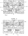
Fig. 1 illustrates one embodiment of a multi-port valve assembly comprising an upper block, a lower block, a diaphragm, and a plurality of one-way valves. -
Fig. 2 illustrates exemplary fluid flow through the valve assembly ofFig. 1 . -
Fig. 3 illustrates further exemplary fluid flow through the valve assembly ofFig. 1 . -
Fig. 4 illustrates yet further exemplary fluid flow through the valve assembly ofFig. 1 . -
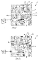
Fig. 5 illustrates one embodiment of a single-port valve assembly comprising an upper block, a lower block, a diaphragm, and a plurality of one-way valves. -
Fig. 6 illustrates exemplary fluid flow through the valve assembly ofFig. 5 . -
Fig. 7 illustrates one embodiment of a rotary union comprising a multi-port valve assembly and circumferential seal. -
Fig. 8 illustrates one embodiment of a rotary union comprising a multi-port valve assembly and a face seal. -
Fig. 9A illustrates one embodiment of a hub cap having an integrated rotary union and single-port valve assembly. -
Fig. 9B illustrates one embodiment of a hub cap having an integrated rotary union and multi-port valve assembly. -
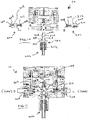
Fig. 10 illustrates an exploded view of one embodiment of a valve assembly comprising one or more port assemblies and a rotary union assembly. -
Fig. 11 illustrates the embodiment ofFig. 10 as assembled. -
Fig. 12 illustrates one embodiment comprising two single-port assemblies connected for use with two vehicle tires. -
Fig. 13 illustrates one embodiment comprising two single-port assemblies comprising a single unit of manufacture for use with two vehicle tires, and having a single fluid inlet. -
Fig. 13B illustrates one embodiment comprising two single-port assemblies connected for use with two vehicle tires, and having a single fluid inlet. -
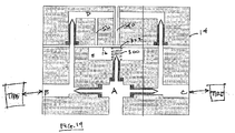
Fig. 14 illustrates one embodiment of a multi-port valve assembly comprising an upper block, a lower block, a diaphragm, spring and a plurality of one-way valves. -
Fig. 15 illustrates a further embodiment of a multi-port valve assembly. - A vehicle tire inflation system may include a valve assembly to allow for inflation and deflation of a vehicle tire. As by now known in the art, a vehicle tire inflation system may comprise a fluid pressure source, such as a tank of compressed air, in sealed fluid communication with one or more vehicle tires through a rotary union.
- A valve assembly may be provided as part of the tire inflation system, for example, as a separate component or as part of a rotary union assembly. As may be seen in the embodiment of
Fig. 1 , a valve assembly 10 (seen in cross-section view) may comprise alower block 12 and anupper block 14. Adiaphragm 16 may be disposed between the lower block and the upper block. One or more one-way valves way valves - In some embodiments, a one-
way valve 26 may be disposed between a fluid chamber A and fluid chamber E so as to allow a pressurizing fluid to flow from the fluid chamber A to the fluid chamber E. In one embodiment, the one-way valve 26 may comprise an elastomeric gland, such as an o-ring 30, disposed about afluid channel 32 and covering orifices 34 formed in the fluid channel.Fluid channel 32 may be in full fluid communication with fluid chamber A. When the fluid pressure in fluid chamber E is lower than the fluid pressure in fluid chamber A, pressurizing fluid from thefluid channel 32 may urge thegland 30 away from the orifices 34, thus allowing fluid to flow from fluid chamber A through the orifices 34 into the fluid chamber E. - In some embodiments, a one-
way valve 36 may be disposed about avent 40 so as to allow fluid to flow from thevalve assembly 10 to atmosphere without allowing environmental contaminants to flow into thevalve assembly 10. The one-way valve 36 may comprise an elastomeric gland, such as an o-ring 38, disposed about thevent 40 and coveringorifices 42 formed in thevent 40. As described in further detail below, when the fluid pressure in fluid chamber E is lower than the fluid pressure in a vehicle tire (not shown), pressurizing fluid from the tire may flow through thevent 40 and urge thegland 38 away from the vent orifices, thus allowing fluid to flow from thevent 40 through theorifices 42 out to atmosphere. - Operation of the
valve assembly 10 ofFig. 1 may be understood with reference toFigs. 2-4 . As may be seen inFig. 2 , pressurized fluid may flow at an inlet P into the fluid chamber A from a fluid source (not shown), such as the fluid pressure source for an automatic tire inflation system. If the fluid pressure in fluid chamber E is lower than the fluid pressure influid channel 32, then the fluid may flow into fluid chamber E through the one-way valve 26. - Because one-
way valves way valves - Similarly, because one-
way valve 26 allows fluid to flow from fluid chamber A to fluid chamber E, the fluid pressure in fluid chamber E tends to substantially equalize with the fluid pressure in fluid chamber A. Depending on the material properties and configuration of the one-way valve 26, the fluid pressures in fluid chamber E and in fluid chamber A may be substantially equal, e.g., within ±2 psi. - If the fluid pressure in ports B and C is lower than the fluid pressure in chamber A, then pressurized fluid from the fluid source may flow into chamber A, through the one-
way valves fluid channel 32 may flow into chamber E, through the one-way valve 26. - Thus, if vehicle tires are in fluid communication with ports C and B, pressurized fluid may be provided to fluid chamber A at a pressure suitable for proper tire inflation. If the vehicle tires are under-inflated or at a pressure lower than the pressure of fluid provided in fluid chamber A, then pressurizing fluid may flow from fluid chamber A through one-
way valves - As may be seen in
Fig. 3 , pressurizing fluid may also flow from ports B and C intofluid channels way valves way valves - Fluid chamber D may be in fluid communication with
diaphragm 16 through relief channel 50.Diaphragm 16 may thus serve as a flexible barrier between fluid chamber E and the relief channel 50. If the fluid pressure in fluid chamber E is greater than or substantially equal to the fluid pressure in relief channel 50, then the diaphragm may seal therelief channel outlet 52 andvent inlet 54. - Under some circumstances, however, the fluid pressure in chamber D may exceed the fluid pressure in chamber E. Such circumstance may arise, for example, if a vehicle tire is over-inflated. Over-inflation may occur from, for example, elevation changes and temperature changes, such as by absorbing radiant energy (e.g., the tire is exposed to sunlight) and normal road use. If the tires are in two-way fluid communication with the valve assembly, then increased tire pressure will result in similarly increased pressure at ports B and C. The one-
way valves way valves - For example, as may be seen in
Fig. 4 , if a tire in two-way fluid communication with port C is over-inflated (perhaps as a result of sitting in the sun), then the fluid pressure in port C will similarly increase. Thus, port C will contain fluid at a greater pressure than the fluid in chamber A. The one-way valve 18 will prevent fluid from flowing to chamber A. The one-way valve 24 will allow pressurized fluid to flow into chamber D, thus raising the pressure in chamber D above that of chamber A (and fluid chamber E, which may be at a substially equal pressure as fluid chamber A). The one-way valve 22 may prevent pressurized fluid from flowing from chamber D into port B. Relief channel 50 may then communicate that pressure todiaphragm 16, which may, due to the pressure differential between fluid chambers D and E, flex away fromrelief channel outlet 52 andvent inlet 54, thus allowing fluid communication between the relief channel 50 and thevent 40. Fluid may flow from the relief channel 50 to thevent 40 and out to atmosphere until the pressure in chamber D and the pressure in chamber E equalize sufficiently to allow the diaphragm to return to its original position, sealing the relief channel outlet 50. Thus, thediaphragm 16 may allow for excess fluid pressure in a tire to be released through thevent 40 until the tire fluid pressure decreases to approximately the pressure in chamber A (the pressure of the fluid source). - As may be seen in
Figs 5-6 , a valve assembly may also be suitable configured for use with a single tire, such as a super single. Avalve assembly 10 may comprise alower block 12 and anupper block 14. Adiaphragm 16 may be disposed between the lower block and the upper block. A one-way valve 20 may be disposed in various fluid channels of the valve assembly. One-way valve 20 may comprise a flexible material and configuration, such as an elastomeric duck-bill valve. A single vehicle tire (not shown) may be disposed in sealed fluid communication with port B. - In some embodiments, a one-
way valve 26 may be disposed between a fluid chamber A and fluid chamber E so as to allow a pressurizing fluid to flow from the fluid chamber A to the fluid chamber E. The one-way valve 26 may comprise an elastomeric gland, such as an o-ring 30, disposed about afluid channel 32 and covering orifices 34 formed in the fluid channel.Fluid channel 32 may be in full fluid communication with fluid chamber A. When the fluid pressure in fluid chamber E is lower than the fluid pressure in fluid chamber A, pressurizing fluid from thefluid channel 32 may urge thegland 30 away from the orifices 34, thus allowing fluid to flow from fluid chamber A through the orifices 34 into the fluid chamber E. - In some embodiments, a one-
way valve 36 may be disposed about avent 40 so as to allow fluid to flow from thevalve assembly 10 to atmosphere without allowing environmental contaminants to flow into thevalve assembly 10. The one-way valve 36 may comprise an elastomeric gland, such as an o-ring 38, disposed about thevent 40 and coveringorifices 42 formed in the vent. In other embodiments, the one-way valve 36 may comprise an elastomeric duck-bill valve. - As with the multiple-port embodiment described above, operation of the single-port valve assembly may be understood with reference to
Figs. 5 and 6 . As may be seen inFig. 5 , pressurized fluid may flow into the fluid chamber A from a fluid source, such as the pressure source for an automatic tire inflation system. If the fluid pressure in fluid chamber A is lower than the fluid pressure influid channel 32, then the fluid may flow into fluid chamber A through the one-way valve 26. - The fluid pressure in port B tends to substantially equalize with the fluid pressure in fluid chamber A through the one-
way valve 20. Similarly, because one-way valve 26 allows fluid to flow from fluid chamber A to fluid chamber E, the fluid pressure in fluid chamber E tends to substantially equalize with the fluid pressure in fluid chamber A. - If the fluid pressure in port B is lower than the fluid pressure in chamber A, then pressurized fluid from the fluid source may flow into chamber A, through the one-
way valve 20, and into port B, and from that port to the tire, thus inflating the tire to the pressure of the fluid provided through thefluid channel 32. Similarly, if the fluid pressure in fluid chamber E is lower than the fluid pressure in chamber A, then pressurized fluid fromfluid channel 32 may flow into chamber E, through the one-way valve 26. - Thus, if the vehicle tire is under-inflated or at a pressure lower than the pressure of fluid provided in fluid chamber A, then pressurizing fluid may flow from fluid chamber A through one-
way valve 20, into the vehicle tire through port B. Pressurizing fluid may also flow from port B intofluid channel 46, and into fluid chamber D. Thus, the fluid pressure in fluid chamber D tends to substantially equalize with the fluid pressure in port B. - Fluid chamber D may be in fluid communication with
diaphragm 16 through relief channel 50.Diaphragm 16 may thus serve as a flexible barrier between fluid chamber E and the relief channel 50. If the fluid pressure in fluid chamber E is greater than or substantially equal to the fluid pressure in relief channel 50, then the diaphragm may seal therelief channel outlet 52 and ventinlet 54. - Under some circumstances, however, the fluid pressure in chamber D may exceed the fluid pressure in chamber E. If the tire is in two-way fluid communication with the valve assembly, then increased tire pressure will result in similarly increased pressure at port B. The one-
way valve 20 will prevent over-pressurized fluid from returning to fluid chamber A. - As may be seen in
Fig. 6 , if a tire in two-way fluid communication with port B is over-inflated (perhaps as a result of sitting in the sun), then port B will contain fluid at a greater pressure than the fluid in fluid chambers A and E. The one-way valve 20 will prevent fluid from flowing to chamber A. Pressurized fluid may flow into chamber D, thus raising the pressure in chamber D above that of chamber E. Relief channel 50 may then communicate that pressure to diaphragm 16, which may, due to the pressure differential between fluid chambers D and E, flex away fromrelief channel outlet 52 and ventinlet 54, thus allowing fluid communication between the relief channel 50 and thevent 40. Fluid may flow from the relief channel 50 to thevent 40 and out to atmosphere until the pressure in chamber D and the pressure in chamber E equalize sufficiently to allow the diaphragm to return to its original position, sealing the relief channel outlet 50. Thus, thediaphragm 16 may allow for excess fluid pressure in a tire to be released through thevent 40 until the tire fluid pressure decreases to approximately the pressure in chamber A (the pressure of the fluid source). - As may be seen in
Fig. 6 , and also similarly as described above, when the fluid pressure in fluid chamber E is lower than the fluid pressure in a vehicle tire (not shown) connected to port B, pressurizing fluid from the tire may flow through thevent 40 and urge the gland away from the vent orifices, thus allowing fluid to flow from thevent 40 through theorifices 42 out to atmosphere. - The valve assembly upper block and lower block may be assembled using conventional fasteners, such as threaded fasteners, locks, clamps, or may be joined by any suitable means. The diaphragm may be retained between the upper and lower block by friction fit, clamp ring, or any other suitable means. In the disclosed embodiment the diaphragm may comprise an elastomeric sheet clamped between the upper block and the lower block of the valve assembly. In other embodiments, a valve assembly may comprise a unitary block having a diaphragm, fluid channels and valves disposed therein as described above.
- In yet further embodiments, the valve assembly may comprise a portion of a rotary union or rotary air connection for a tire inflation system. For example, as may be seen in
Fig. 7 , a rotary air connection may be provided as generally described inUS Patent 6,698,482 . Avalve body 12 may have atubular member 70 disposed in aninlet 72. Thetubular member 70 may rotate with respect to thevalve body 12. A bearing 74 may be disposed between anend 76 of thetubular member 70 and aface 78 of the inlet. Afluid channel 80 in the bearing 74 may allow pressurized fluid to flow from thetubular member 70 into the fluid chamber A. A seal 84, such as an o-ring or lip seal, may be disposed about thetubular member 70 so as to seal thetubular member 70 andvalve body 12. Acap 82 may be disposed in the inlet about thetubular member 70 so as to retain theend 76 of thetubular member 70 and bearing 74 in the valve body. Thetubular member 70 may be rigid, flexible, or a combination of rigid and flexible members. - A valve assembly (whether for one or more vehicle tires) as described herein may be used in connection with any other rotary air connection suitable for a vehicle tire inflation system. For example, as may be seen in
Fig. 8 , aface seal 80 may be provided in connection with thevalve body 10, such as the face seal disclosed inUS Patent 6,105,645 . The rotary union may comprise a rigidtubular member 82, a graphite member 84 and aspring 86. Thespring 86 and graphite member 84 may be disposed in aninlet 88 of thevalve body 12. Thespring 86 may urge the graphite member 84 against therigid tubular member 82, thereby forming aface seal 80. Bearings 90 may allow thevalve body 12 to rotate with respect to therigid tubular member 82. Therigid tubular member 82 may be sealingly connected to a flexible tubular member 92, which may in turn be sealingly connected to a fluid source in an axle 99. Pressurized fluid may flow through the flexible tubular member 92, rigid tubular member, graphite member 84 andspring 86 into fluid chamber A. Fluid may flow through thevalve body 10 from fluid chamber A as described above. The rigid member 8 may comprise metal, plastic or ceramic. A washer 96 and o-ring 98 may be disposed between thespring 86 and graphite member 84. Thevalve body 10 may be mounted to the exterior of ahubcap 100. Ports B and C may each be sealingly connected to a vehicle tire. - Similarly, as may be seen in
Figs. 9A and 9B , thevalve assembly 10 may be incorporated into a hub cap rotary union, such as the rotary connection ofUS Patent 8,505,600 . In the embodiment ofFig. 9 , ahub cap 110 may comprise a rotary union stem 112 rotatably mounted to ahub cap boss 114 by bearings 116. Anelastomeric seal 120, such as a lip seal, may seal the rotary union stem 112 with respect to the hubcap. The rotary union stem 112 may be in sealed fluid communication with a fluid source. Pressurized fluid may flow from the pressurized fluid source in theaxle 118 through the rotary union stem into the fluid chamber A. Fluid may flow through thevalve body 10 from fluid chamber A as described above. In the embodiment ofFig. 9A , port B may be sealingly connected to a first vehicle tire. In the embodiment ofFig. 9B , a second port C may be provided as described herein, and be sealingly connected to a second vehicle tire. One-way valves way valve 18, 20), or may comprise elastomeric ring-shaped glands (as with one-way valves 26) or any other suitable one-way valve. - In other embodiments, a valve assembly (whether for single or multiple vehicle tires) may be similarly incorporated into a hubcap rotary union, such as the rotary union disclosed in applicant's PCT App. Ser. No.
PCT/2014/061879 filed October 23, 2014 . - Use of flexible one-way valves and a diaphragm may allow better equalization of fluid pressures in the fluid chambers A, D and E and ports B and C than that permitted by use of metallic or non-elastomeric valves, such as Schraeder valves. Such valves may comprise elastomeric duck-bill configuration of, e.g., silicon or rubber, or may comprise the o-ring glands or annular seals covering orifices as described herein.
- As may be further seen in the embodiment of
Fig. 10 , avalve assembly 10 may comprise one ormore port assemblies 200 and arotary union assembly 202. Aport assembly 200 may comprise aport body 204 having aport channel 206 disposed therein. A one-way valve port channel 206. Aport vent 207 may allow fluid from the port channel to flow from theport body 204. Theport body 204 may comprise aport end 208 and ahose end 210. The port end may be threaded for removable connection tovalve assembly 10, e.g., at ports B and C. Anelastomeric seal 212, such as an o-ring, may be disposed about the outer circumference of the port body so as to provide sealed connection between thevalve assembly 10 and theport assembly 200. Thehose end 210 may be suitably configured, such as by screw threads, for fluid-tight connection to a fluid conduit in fluid communication with a pneumatic tire (not shown). - The
rotary union assembly 202 may comprise a valve end 214 and ahub end 216. Therotary union assembly 202 may comprise apressure body 220 having apressure channel 222 disposed therein. The valve end may be configured, e.g., with screw threads, for removable connection tovalve assembly 10 at an inlet P to fluid chamber A. Thehub end 216 may be configured, e.g., with screw threads, for removable connection to a hub cap (not shown). Anelastomeric seal 218, such as an o-ring, may be disposed about the outer circumference of the rotary union body so as to provide sealed connection between thevalve assembly 10 and therotary union assembly 202. One or more pressure vents 224 may allow fluid from the pressure channel to flow from thepressure body 220. The rotary union assembly may further comprise anysuitable rotary union 226, such as a rotary union of the type shown inFig. 7 . - As may be seen in the embodiment of
Fig. 11 , when theport assemblies 200 androtary union assembly 202 are assembled to thevalve assembly 10. So assembled, theport assemblies 200 androtary union 202 assembly form fluid flow paths similar to that of the embodiment ofFig. 1 . Furthermore,rotary union assembly 226 may serve to retain one-way valve 26 in thevalve assembly 10. For example, pressurized fluid may flow from a fluid source through therotary union assembly 226 into the fluid chamber A through the pressure vents 224. Pressurized fluid may flow from the fluid chamber A through the one-way valves port vent 207 and through one-way valve 24 as described in connection withFigs. 3-4 . Advantageously, providing one-way valves in assemblies removable from thevalve assembly 10 may allow for easier insertion and removal of such valves from thevalve assembly 10. - As may be seen in the embodiment of
Fig. 12 , a plurality of single-port valve assemblies 10, such as that ofFig. 5 , may be arranged to provide valved fluid flow to more than one tire (not shown). - In the embodiment of
Fig. 13A , avalve assembly 10 may be provided with a plurality of fluid chambers E, with fluid chamber E-1 and fluid chamber E-2 corresponding to a port B and a port C, respectively. Fluid chamber A may provide pressurized fluid to fluid chambers E-1 and E-2. The valve assembly ofFig. 13 may operate similarly as the embodiment ofFig. 12 , except where pressurized fluid may be provided at a single inlet P rather than multiple inlets.Fig. 13B illustrates a similar embodiment, but comprising more than one assembly. - As may be seen in the embodiment of
Fig. 14 , aspring 300 or other vibration damping device may be disposed in fluid chamber A so as to co-act withdiaphragm 16. So disposed, the spring may reduce or eliminate vibration of diaphragm against theupper valve body 14. Vibration of the diaphragm may occur from road conditions, or jarring forces while at rest, or fluid pressure impulses. Vibrational movement of the diaphragm may allow fluid to flow from relief channel 50 to vent 40 even when there is little to no pressure imbalance between fluid chambers A and E, thus deflating tires (not shown) connected to ports B and C. The spring may provide a relatively light force, e.g., equivalent of 1-5 psi, against thediaphragm 16. A buffer 302 may be disposed between thespring 300 and thediaphragm 16 so as to reduce wear. In some embodiments, the elasticity of the diaphragm may allow for a pressure imbalance of 0-3 psi between fluid chambers A and D. A spring may increase that pressure imbalance by a further 15 psi. Ideally, the one or more one-way valves, diaphragm and optional spring should allow for overpressurized tires to deflate to <10 psi over the fluid pressure in chamber A. -
Fig. 15 discloses a single-tire embodiment comprising a disassembled view of avalve assembly 10. Arotary union assembly 600 similar to the rotary union assembly ofFig. 11 may be removably connected to alower valve body 602. Therotary union assembly 600 may comprise a rotary union body 604 and a telescope cap 606 that may retain one end of a tubular member (608), a lip-seal or other elastomeric seal (not shown) and a bearing (not shown) in the rotary union body 604. An elastomeric flange 610 may be further provided to ventably seal hubcap vent holes (not shown) when thevalve assembly 10 is mounted to a hubcap in the manner described in connection withFig. 10 . Therotary union assembly 600 may, when connected to thelower valve body 602, retain a one-way valve 612 in the lower valve body as described in connection with the one-way valve 26 ofFigs. 10 and 11 . - Similarly, a
port assembly 614 as described in connection withFigs. 10 and 11 may be provided. A diaphragm 616 may be sandwiched between the lower valve body and upper valve body 618. In the embodiment ofFig. 15 , the diaphragm may comprise a smaller maximum dimension than the valve assembly, and may be disposed in a corresponding seat 620 formed in thevalve assembly 10. A spring 622 and spring cap 624 may be used, as described in connection withFig. 14 for vibration dampening. Thevalve assembly 10 may be removably assembled by bolts 626 or other suitable means. A multiple-port embodiment may be similarly constructed according to the teachings contained herein. - Although the disclosed subject matter and its advantages have been described in detail, it should be understood that various changes, substitutions and alterations can be made herein without departing from the invention as defined by the appended claims.
Claims (15)
- A valve body comprising:an inlet (P) configured to receive pressurized fluid;a first port (B);a diaphragm (16, 616) comprising a first side and an opposing second side;two one-way valves disposed as follows:a first one-way valve (26) disposed so as to allow fluid to flow from the inlet to the first side of the diaphragm, anda second one-way valve (20) disposed so as to allow fluid to flow from the inlet to the first port;wherein the second side of the diaphragm (16, 616) is in fluid communication with the first port (B) and with atmosphere, and the first side of the diaphragm (16, 616) is in fluid communication with the first one-way valve (26), such that when fluid pressure in the first port (B) approximately equals fluid pressure at the first valve (26), the diaphragm (16, 616) substantially seals the first port (B) from atmosphere, and when fluid pressure in the first port (B) exceeds fluid pressure at the first one-way valve (26), the diaphragm (16, 616) may flex to allow fluid to flow from the first port (B) to atmosphere.
- The valve body of claim 1, further comprising:a second port (C);three one-way valves disposed as follows:a third one-way valve (18) disposed so as to allow fluid to flow from the inlet to the second port,a fourth one-way valve (22) disposed so as to allow fluid to flow from the first port to the second side of the diaphragm, anda fifth one-way valve (24) disposed so as to allow fluid to flow from the second port to the second side of the diaphragm.
- The valve body of claim 2, further comprising a sixth one-way valve (36) disposed so as to allow fluid to flow to atmosphere.
- The valve body of claim 2, wherein each of the one-way valves may comprise an elastomeric gland (30) sealing a fluid orifice or an elastomeric duck-bill valve.
- The valve body of claim 1, further comprising:
a rotary union formed by a tubular member (70, 82, 112) sealingly connected to and rotatable with respect to the valve body (12) at the inlet. - The valve body of claim 5, wherein an elastomeric seal (84) provides the sealing connection of the tubular member to the valve body.
- The valve body of claim 6, wherein the elastomeric seal (84) is one of an o-ring and a lip seal.
- The valve body of claim 5, wherein a face seal (80) provides the sealing connection of the tubular member to the valve body.
- The valve body of claim 8, the face seal (80) comprising a graphite member (84) disposed within the inlet, a rigid member (82) sealingly coupled to the tubular member, and a spring (86) disposed within the inlet so as to urge the graphite member toward the rigid member.
- The valve body of claim 5, wherein the valve body is part of a vehicle hub cap (110).
- The valve body of claim 5, the rotary union (202) configured for removable connection to the inlet.
- The valve body of claim 1 further comprising:a port body (204) removably disposed in the first port, the port body having a port channel (206) and a port vent (207) in fluid communication with the first side of the diaphragm; andthe second one way valve disposed in the port channel so as to allow fluid to flow through the port channel and port vent.
- The valve body of claim 1 further comprising a rotary union assembly (202) removably disposed in the inlet, the rotary union assembly comprising:a body (220) having a fluid channel (222) and one or more vents (224), the body having an end configured to abut the first one-way valve; anda rotary union (226) disposed in the fluid channel.
- The valve body of claim 13, wherein the rotary union further comprises either:a tubular member (70) disposed in the fluid channel and an elastomeric circumferential seal (84) forming a sealing connection between the tubular member and the body; ora graphite member (84) and a rigid member (82), the rigid member abutting the graphite member so as to form a face seal (80).
- The valve body of claim 1, further comprising a spring (300) disposed between the valve body and the first side of the diaphragm (16).
Applications Claiming Priority (2)
| Application Number | Priority Date | Filing Date | Title |
|---|---|---|---|
| US201462009803P | 2014-06-09 | 2014-06-09 | |
| PCT/US2015/034953 WO2015191621A1 (en) | 2014-06-09 | 2015-06-09 | Valve assembly |
Publications (3)
| Publication Number | Publication Date |
|---|---|
| EP3152069A1 EP3152069A1 (en) | 2017-04-12 |
| EP3152069A4 EP3152069A4 (en) | 2018-02-14 |
| EP3152069B1 true EP3152069B1 (en) | 2019-06-05 |
Family
ID=54834206
Family Applications (1)
| Application Number | Title | Priority Date | Filing Date |
|---|---|---|---|
| EP15806565.6A Active EP3152069B1 (en) | 2014-06-09 | 2015-06-09 | Valve assembly |
Country Status (9)
| Country | Link |
|---|---|
| US (1) | US10259273B2 (en) |
| EP (1) | EP3152069B1 (en) |
| CN (2) | CN106488849B (en) |
| AU (2) | AU2015274772A1 (en) |
| CA (1) | CA2951873A1 (en) |
| ES (1) | ES2733364T3 (en) |
| MX (1) | MX2016015938A (en) |
| TR (1) | TR201908724T4 (en) |
| WO (1) | WO2015191621A1 (en) |
Families Citing this family (4)
| Publication number | Priority date | Publication date | Assignee | Title |
|---|---|---|---|---|
| WO2017156351A1 (en) * | 2016-03-09 | 2017-09-14 | Equalaire Systems, Inc. | Pressure equalization valve assembly |
| WO2018075826A1 (en) | 2016-10-19 | 2018-04-26 | Equalaire Systems, Inc. | Inflation manifold |
| CN110739440B (en) * | 2019-11-20 | 2025-07-29 | 湖南领湃科技集团股份有限公司 | Integrated double-channel valve and battery cover plate |
| CN114909492B (en) * | 2022-06-13 | 2026-03-31 | 费斯托(中国)自动化制造有限公司 | A sealing control structure for a valve and a valve device |
Family Cites Families (37)
| Publication number | Priority date | Publication date | Assignee | Title |
|---|---|---|---|---|
| DE3148729A1 (en) * | 1981-03-05 | 1982-09-23 | Robert Bosch Gmbh, 7000 Stuttgart | TIRE PRESSURE CONTROL SYSTEM |
| US4640331A (en) * | 1984-06-04 | 1987-02-03 | Eaton Corporation | Central tire inflation system |
| CN1003359B (en) * | 1985-06-18 | 1989-02-22 | 伊顿有限公司 | Centralized tire inflation system |
| US4705090A (en) * | 1986-01-17 | 1987-11-10 | Tire Inflation Systems Corp. | Apparatus for controlling air pressure in vehicle tires |
| US4893664A (en) * | 1988-09-12 | 1990-01-16 | Eaton Corporation | Wheel end valve for central tire inflation system |
| JP2964766B2 (en) | 1992-03-07 | 1999-10-18 | 株式会社デンソー | Tire pressure control valve |
| CN1038157C (en) * | 1992-09-30 | 1998-04-22 | 中国人民解放军运输工程学院 | Pressure fluid direction control valve and its application in tyre pressure adjusting device |
| US6161565A (en) * | 1996-04-08 | 2000-12-19 | Conroy, Sr.; Joseph P. | Pneumatic control |
| US5769979A (en) * | 1996-08-30 | 1998-06-23 | Equalaire Systems, Inc. | Rotary air connection for tire inflation system |
| US6105645A (en) * | 1998-05-14 | 2000-08-22 | Ingram; Anthony L. | Rotary union assembly for use in air pressure inflation systems for tractor trailer tires |
| FR2822918B1 (en) * | 2001-03-30 | 2003-06-13 | Henri Beau | PNEUMATIC PILOT DEVICE FOR AUTOMATIC INFLATION-DEFLATION OF A CONTAINMENT CAPACITY OF A GAS FLUID UNDER RELATIVE PRESSURE |
| US7669465B2 (en) | 2002-04-10 | 2010-03-02 | John Becker | Systems and methods for maintaining air pressure in tires |
| US7530379B1 (en) | 2002-04-10 | 2009-05-12 | John Henry Becker | Tire inflation system |
| KR200335582Y1 (en) * | 2003-08-30 | 2003-12-06 | 박진철 | An Air Supply Apparatus of Tire for a Car |
| CN100406319C (en) * | 2006-08-10 | 2008-07-30 | 三一重工股份有限公司 | Tyre air inflating device of tyre road pressing machine |
| US8006731B2 (en) * | 2006-12-22 | 2011-08-30 | Hutchinson S.A. | Apparatus and system for integration of a central tire inflation valve into a wheel |
| FR2922484B1 (en) * | 2007-10-23 | 2016-06-03 | Messier Bugatti | DEVICE FOR CONNECTING AN AIRCRAFT WHEEL TIRE TO A PNEUMATIC AIRCRAFT CONTROL PANEL |
| US8069890B2 (en) * | 2008-04-25 | 2011-12-06 | Hutchinson S.A. | Hub bore mounted central tire inflation valve system |
| CN201739566U (en) * | 2010-04-02 | 2011-02-09 | 武汉元丰汽车技术发展有限公司 | Axle valve assembly of automobile tire central inflation/deflation system |
| EP2582977A4 (en) * | 2010-06-21 | 2017-05-03 | Equalaire Systems, Inc. | Rotary air connection with central valve for tire inflation system |
| WO2012016195A1 (en) | 2010-07-30 | 2012-02-02 | Hendrickson Usa, L.L.C. | Constant pressure pneumatic balancing tire inflation system |
| US9434216B2 (en) | 2010-07-30 | 2016-09-06 | Hendrickson Usa, L.L.C. | Tire inflation system with discrete deflation circuit |
| CN105644278B (en) | 2010-07-30 | 2018-02-16 | 亨德里克森美国有限责任公司 | Tire inflation system with discrete deflation loop |
| CN104040455B (en) * | 2011-08-17 | 2016-06-29 | 亨德里克森美国有限责任公司 | Axletree aerating system |
| FR2979853B1 (en) * | 2011-09-13 | 2013-09-20 | Stephane Fazekas | PNEUMATIC PILOT DEVICE FOR AUTOMATIC INFLATING-DEFLATION OF A TIRE, IN PARTICULAR |
| US20130146193A1 (en) | 2011-12-12 | 2013-06-13 | HSM Tire Company | Tire pressure equalization system |
| EP2836376B1 (en) | 2012-04-09 | 2020-03-04 | Dana Heavy Vehicle Systems Group, LLC | Tire inflation system |
| MX354548B (en) | 2012-07-13 | 2018-03-09 | Dana Heavy Vehicle Sys Group | Valve assemblies and methods of inflating or deflating a tyre. |
| CN105189151B (en) * | 2013-02-11 | 2018-01-26 | 德纳重型车辆系统集团有限责任公司 | Valve Assemblies for Central Tire Inflation Systems |
| EP2969601A1 (en) | 2013-03-15 | 2016-01-20 | Dana Heavy Vehicle Systems Group, LLC | Method of venting a tire inflation system and control unit utilized therein |
| WO2015006462A1 (en) * | 2013-07-09 | 2015-01-15 | Parker-Hannifin Corporation | Pressure and temperature compensated control valve assembly |
| US20150096655A1 (en) | 2013-10-09 | 2015-04-09 | Arvinmeritor Technology, Llc. | Tire Inflation System Having a Pressure Equalization Valve Assembly |
| US9346329B2 (en) | 2013-11-15 | 2016-05-24 | Arvinmeritor Technology, Llc | Tire inflation system and method of control |
| US20150090386A1 (en) | 2013-09-30 | 2015-04-02 | The Goodyear Tire & Rubber Company | Air maintenance tire and valve assembly |
| CN203528218U (en) * | 2013-10-15 | 2014-04-09 | 北京固瑞驰航空设备技术有限公司 | Air inflation nozzle of aircraft tire |
| US9248707B2 (en) | 2013-12-25 | 2016-02-02 | Joe Huayue Zhou | Intelligent tire inflation and deflation system apparatus |
| US9278587B2 (en) | 2014-01-21 | 2016-03-08 | Arvinmeritor Technology, Llc | Tire inflation system and method of control |
-
2015
- 2015-06-09 ES ES15806565T patent/ES2733364T3/en active Active
- 2015-06-09 US US15/317,863 patent/US10259273B2/en active Active
- 2015-06-09 AU AU2015274772A patent/AU2015274772A1/en not_active Abandoned
- 2015-06-09 WO PCT/US2015/034953 patent/WO2015191621A1/en not_active Ceased
- 2015-06-09 MX MX2016015938A patent/MX2016015938A/en unknown
- 2015-06-09 TR TR2019/08724T patent/TR201908724T4/en unknown
- 2015-06-09 CN CN201580031020.8A patent/CN106488849B/en not_active Expired - Fee Related
- 2015-06-09 CN CN201810899807.1A patent/CN108973539A/en active Pending
- 2015-06-09 EP EP15806565.6A patent/EP3152069B1/en active Active
- 2015-06-09 CA CA2951873A patent/CA2951873A1/en not_active Abandoned
-
2019
- 2019-04-15 AU AU2019202612A patent/AU2019202612B2/en not_active Ceased
Non-Patent Citations (1)
| Title |
|---|
| None * |
Also Published As
| Publication number | Publication date |
|---|---|
| EP3152069A1 (en) | 2017-04-12 |
| AU2015274772A1 (en) | 2017-01-12 |
| CN108973539A (en) | 2018-12-11 |
| CN106488849A (en) | 2017-03-08 |
| US10259273B2 (en) | 2019-04-16 |
| CN106488849B (en) | 2018-07-06 |
| ES2733364T3 (en) | 2019-11-28 |
| TR201908724T4 (en) | 2019-07-22 |
| MX2016015938A (en) | 2017-03-20 |
| AU2019202612A1 (en) | 2019-05-09 |
| EP3152069A4 (en) | 2018-02-14 |
| WO2015191621A1 (en) | 2015-12-17 |
| AU2019202612B2 (en) | 2020-07-09 |
| US20170120696A1 (en) | 2017-05-04 |
| CA2951873A1 (en) | 2015-12-17 |
Similar Documents
| Publication | Publication Date | Title |
|---|---|---|
| AU2019202612B2 (en) | Valve assembly | |
| CN103260913B (en) | Stem with auxiliary port | |
| CA2728611C (en) | Pressure controlled three way valve device | |
| CN109070663B (en) | Pressure equalizing valve assembly | |
| AU2011271099B2 (en) | Rotary air connection with central valve for tire inflation system | |
| EP1219874A1 (en) | Pressure-controlled three-way valve device | |
| US20140183826A1 (en) | Rotating sealing device and sealing ring for such device | |
| EP3339062A1 (en) | Inlet control valve for an air maintenance tire | |
| HK1235359A1 (en) | Valve assembly | |
| HK40001840A (en) | Pressure equalization valve assembly | |
| HK40001840B (en) | Pressure equalization valve assembly | |
| US20250206077A1 (en) | Tire pressure equalization systems and valves | |
| HK1186440B (en) | Valve stem with auxiliary port |
Legal Events
| Date | Code | Title | Description |
|---|---|---|---|
| STAA | Information on the status of an ep patent application or granted ep patent |
Free format text: STATUS: THE INTERNATIONAL PUBLICATION HAS BEEN MADE |
|
| PUAI | Public reference made under article 153(3) epc to a published international application that has entered the european phase |
Free format text: ORIGINAL CODE: 0009012 |
|
| STAA | Information on the status of an ep patent application or granted ep patent |
Free format text: STATUS: REQUEST FOR EXAMINATION WAS MADE |
|
| 17P | Request for examination filed |
Effective date: 20170104 |
|
| AK | Designated contracting states |
Kind code of ref document: A1 Designated state(s): AL AT BE BG CH CY CZ DE DK EE ES FI FR GB GR HR HU IE IS IT LI LT LU LV MC MK MT NL NO PL PT RO RS SE SI SK SM TR |
|
| AX | Request for extension of the european patent |
Extension state: BA ME |
|
| DAV | Request for validation of the european patent (deleted) | ||
| DAX | Request for extension of the european patent (deleted) | ||
| A4 | Supplementary search report drawn up and despatched |
Effective date: 20180116 |
|
| RIC1 | Information provided on ipc code assigned before grant |
Ipc: B60C 23/00 20060101AFI20180110BHEP Ipc: F16K 15/20 20060101ALI20180110BHEP |
|
| GRAP | Despatch of communication of intention to grant a patent |
Free format text: ORIGINAL CODE: EPIDOSNIGR1 |
|
| RIC1 | Information provided on ipc code assigned before grant |
Ipc: F16K 15/20 20060101ALI20180827BHEP Ipc: B60C 23/00 20060101AFI20180827BHEP |
|
| STAA | Information on the status of an ep patent application or granted ep patent |
Free format text: STATUS: GRANT OF PATENT IS INTENDED |
|
| INTG | Intention to grant announced |
Effective date: 20181004 |
|
| GRAJ | Information related to disapproval of communication of intention to grant by the applicant or resumption of examination proceedings by the epo deleted |
Free format text: ORIGINAL CODE: EPIDOSDIGR1 |
|
| STAA | Information on the status of an ep patent application or granted ep patent |
Free format text: STATUS: REQUEST FOR EXAMINATION WAS MADE |
|
| INTC | Intention to grant announced (deleted) | ||
| GRAP | Despatch of communication of intention to grant a patent |
Free format text: ORIGINAL CODE: EPIDOSNIGR1 |
|
| STAA | Information on the status of an ep patent application or granted ep patent |
Free format text: STATUS: GRANT OF PATENT IS INTENDED |
|
| INTG | Intention to grant announced |
Effective date: 20190308 |
|
| RIN1 | Information on inventor provided before grant (corrected) |
Inventor name: HENRY, DANE Inventor name: HENNIG, MARK, KEVIN |
|
| GRAS | Grant fee paid |
Free format text: ORIGINAL CODE: EPIDOSNIGR3 |
|
| GRAA | (expected) grant |
Free format text: ORIGINAL CODE: 0009210 |
|
| STAA | Information on the status of an ep patent application or granted ep patent |
Free format text: STATUS: THE PATENT HAS BEEN GRANTED |
|
| AK | Designated contracting states |
Kind code of ref document: B1 Designated state(s): AL AT BE BG CH CY CZ DE DK EE ES FI FR GB GR HR HU IE IS IT LI LT LU LV MC MK MT NL NO PL PT RO RS SE SI SK SM TR |
|
| REG | Reference to a national code |
Ref country code: GB Ref legal event code: FG4D |
|
| REG | Reference to a national code |
Ref country code: CH Ref legal event code: EP |
|
| REG | Reference to a national code |
Ref country code: AT Ref legal event code: REF Ref document number: 1139615 Country of ref document: AT Kind code of ref document: T Effective date: 20190615 |
|
| REG | Reference to a national code |
Ref country code: DE Ref legal event code: R096 Ref document number: 602015031504 Country of ref document: DE |
|
| REG | Reference to a national code |
Ref country code: IE Ref legal event code: FG4D |
|
| REG | Reference to a national code |
Ref country code: NL Ref legal event code: FP |
|
| REG | Reference to a national code |
Ref country code: LT Ref legal event code: MG4D |
|
| PG25 | Lapsed in a contracting state [announced via postgrant information from national office to epo] |
Ref country code: FI Free format text: LAPSE BECAUSE OF FAILURE TO SUBMIT A TRANSLATION OF THE DESCRIPTION OR TO PAY THE FEE WITHIN THE PRESCRIBED TIME-LIMIT Effective date: 20190605 Ref country code: SE Free format text: LAPSE BECAUSE OF FAILURE TO SUBMIT A TRANSLATION OF THE DESCRIPTION OR TO PAY THE FEE WITHIN THE PRESCRIBED TIME-LIMIT Effective date: 20190605 Ref country code: LT Free format text: LAPSE BECAUSE OF FAILURE TO SUBMIT A TRANSLATION OF THE DESCRIPTION OR TO PAY THE FEE WITHIN THE PRESCRIBED TIME-LIMIT Effective date: 20190605 Ref country code: AL Free format text: LAPSE BECAUSE OF FAILURE TO SUBMIT A TRANSLATION OF THE DESCRIPTION OR TO PAY THE FEE WITHIN THE PRESCRIBED TIME-LIMIT Effective date: 20190605 Ref country code: NO Free format text: LAPSE BECAUSE OF FAILURE TO SUBMIT A TRANSLATION OF THE DESCRIPTION OR TO PAY THE FEE WITHIN THE PRESCRIBED TIME-LIMIT Effective date: 20190905 Ref country code: HR Free format text: LAPSE BECAUSE OF FAILURE TO SUBMIT A TRANSLATION OF THE DESCRIPTION OR TO PAY THE FEE WITHIN THE PRESCRIBED TIME-LIMIT Effective date: 20190605 |
|
| REG | Reference to a national code |
Ref country code: ES Ref legal event code: FG2A Ref document number: 2733364 Country of ref document: ES Kind code of ref document: T3 Effective date: 20191128 |
|
| PG25 | Lapsed in a contracting state [announced via postgrant information from national office to epo] |
Ref country code: GR Free format text: LAPSE BECAUSE OF FAILURE TO SUBMIT A TRANSLATION OF THE DESCRIPTION OR TO PAY THE FEE WITHIN THE PRESCRIBED TIME-LIMIT Effective date: 20190906 Ref country code: LV Free format text: LAPSE BECAUSE OF FAILURE TO SUBMIT A TRANSLATION OF THE DESCRIPTION OR TO PAY THE FEE WITHIN THE PRESCRIBED TIME-LIMIT Effective date: 20190605 Ref country code: BG Free format text: LAPSE BECAUSE OF FAILURE TO SUBMIT A TRANSLATION OF THE DESCRIPTION OR TO PAY THE FEE WITHIN THE PRESCRIBED TIME-LIMIT Effective date: 20190905 Ref country code: RS Free format text: LAPSE BECAUSE OF FAILURE TO SUBMIT A TRANSLATION OF THE DESCRIPTION OR TO PAY THE FEE WITHIN THE PRESCRIBED TIME-LIMIT Effective date: 20190605 |
|
| REG | Reference to a national code |
Ref country code: AT Ref legal event code: MK05 Ref document number: 1139615 Country of ref document: AT Kind code of ref document: T Effective date: 20190605 |
|
| PG25 | Lapsed in a contracting state [announced via postgrant information from national office to epo] |
Ref country code: CZ Free format text: LAPSE BECAUSE OF FAILURE TO SUBMIT A TRANSLATION OF THE DESCRIPTION OR TO PAY THE FEE WITHIN THE PRESCRIBED TIME-LIMIT Effective date: 20190605 Ref country code: PT Free format text: LAPSE BECAUSE OF FAILURE TO SUBMIT A TRANSLATION OF THE DESCRIPTION OR TO PAY THE FEE WITHIN THE PRESCRIBED TIME-LIMIT Effective date: 20191007 Ref country code: RO Free format text: LAPSE BECAUSE OF FAILURE TO SUBMIT A TRANSLATION OF THE DESCRIPTION OR TO PAY THE FEE WITHIN THE PRESCRIBED TIME-LIMIT Effective date: 20190605 Ref country code: AT Free format text: LAPSE BECAUSE OF FAILURE TO SUBMIT A TRANSLATION OF THE DESCRIPTION OR TO PAY THE FEE WITHIN THE PRESCRIBED TIME-LIMIT Effective date: 20190605 Ref country code: EE Free format text: LAPSE BECAUSE OF FAILURE TO SUBMIT A TRANSLATION OF THE DESCRIPTION OR TO PAY THE FEE WITHIN THE PRESCRIBED TIME-LIMIT Effective date: 20190605 Ref country code: SK Free format text: LAPSE BECAUSE OF FAILURE TO SUBMIT A TRANSLATION OF THE DESCRIPTION OR TO PAY THE FEE WITHIN THE PRESCRIBED TIME-LIMIT Effective date: 20190605 |
|
| REG | Reference to a national code |
Ref country code: CH Ref legal event code: PL |
|
| PG25 | Lapsed in a contracting state [announced via postgrant information from national office to epo] |
Ref country code: SM Free format text: LAPSE BECAUSE OF FAILURE TO SUBMIT A TRANSLATION OF THE DESCRIPTION OR TO PAY THE FEE WITHIN THE PRESCRIBED TIME-LIMIT Effective date: 20190605 Ref country code: IS Free format text: LAPSE BECAUSE OF FAILURE TO SUBMIT A TRANSLATION OF THE DESCRIPTION OR TO PAY THE FEE WITHIN THE PRESCRIBED TIME-LIMIT Effective date: 20191005 |
|
| REG | Reference to a national code |
Ref country code: DE Ref legal event code: R097 Ref document number: 602015031504 Country of ref document: DE |
|
| REG | Reference to a national code |
Ref country code: BE Ref legal event code: MM Effective date: 20190630 |
|
| PG25 | Lapsed in a contracting state [announced via postgrant information from national office to epo] |
Ref country code: MC Free format text: LAPSE BECAUSE OF FAILURE TO SUBMIT A TRANSLATION OF THE DESCRIPTION OR TO PAY THE FEE WITHIN THE PRESCRIBED TIME-LIMIT Effective date: 20190605 |
|
| PLBE | No opposition filed within time limit |
Free format text: ORIGINAL CODE: 0009261 |
|
| STAA | Information on the status of an ep patent application or granted ep patent |
Free format text: STATUS: NO OPPOSITION FILED WITHIN TIME LIMIT |
|
| PG25 | Lapsed in a contracting state [announced via postgrant information from national office to epo] |
Ref country code: IE Free format text: LAPSE BECAUSE OF NON-PAYMENT OF DUE FEES Effective date: 20190609 Ref country code: DK Free format text: LAPSE BECAUSE OF FAILURE TO SUBMIT A TRANSLATION OF THE DESCRIPTION OR TO PAY THE FEE WITHIN THE PRESCRIBED TIME-LIMIT Effective date: 20190605 Ref country code: PL Free format text: LAPSE BECAUSE OF FAILURE TO SUBMIT A TRANSLATION OF THE DESCRIPTION OR TO PAY THE FEE WITHIN THE PRESCRIBED TIME-LIMIT Effective date: 20190605 |
|
| 26N | No opposition filed |
Effective date: 20200306 |
|
| PG25 | Lapsed in a contracting state [announced via postgrant information from national office to epo] |
Ref country code: SI Free format text: LAPSE BECAUSE OF FAILURE TO SUBMIT A TRANSLATION OF THE DESCRIPTION OR TO PAY THE FEE WITHIN THE PRESCRIBED TIME-LIMIT Effective date: 20190605 Ref country code: BE Free format text: LAPSE BECAUSE OF NON-PAYMENT OF DUE FEES Effective date: 20190630 Ref country code: LU Free format text: LAPSE BECAUSE OF NON-PAYMENT OF DUE FEES Effective date: 20190609 Ref country code: LI Free format text: LAPSE BECAUSE OF NON-PAYMENT OF DUE FEES Effective date: 20190630 Ref country code: CH Free format text: LAPSE BECAUSE OF NON-PAYMENT OF DUE FEES Effective date: 20190630 |
|
| PGFP | Annual fee paid to national office [announced via postgrant information from national office to epo] |
Ref country code: TR Payment date: 20200609 Year of fee payment: 6 Ref country code: DE Payment date: 20200527 Year of fee payment: 6 Ref country code: FR Payment date: 20200512 Year of fee payment: 6 |
|
| PGFP | Annual fee paid to national office [announced via postgrant information from national office to epo] |
Ref country code: NL Payment date: 20200615 Year of fee payment: 6 Ref country code: GB Payment date: 20200527 Year of fee payment: 6 Ref country code: IT Payment date: 20200512 Year of fee payment: 6 |
|
| PGFP | Annual fee paid to national office [announced via postgrant information from national office to epo] |
Ref country code: ES Payment date: 20200701 Year of fee payment: 6 |
|
| PG25 | Lapsed in a contracting state [announced via postgrant information from national office to epo] |
Ref country code: CY Free format text: LAPSE BECAUSE OF FAILURE TO SUBMIT A TRANSLATION OF THE DESCRIPTION OR TO PAY THE FEE WITHIN THE PRESCRIBED TIME-LIMIT Effective date: 20190605 |
|
| PG25 | Lapsed in a contracting state [announced via postgrant information from national office to epo] |
Ref country code: HU Free format text: LAPSE BECAUSE OF FAILURE TO SUBMIT A TRANSLATION OF THE DESCRIPTION OR TO PAY THE FEE WITHIN THE PRESCRIBED TIME-LIMIT; INVALID AB INITIO Effective date: 20150609 Ref country code: MT Free format text: LAPSE BECAUSE OF FAILURE TO SUBMIT A TRANSLATION OF THE DESCRIPTION OR TO PAY THE FEE WITHIN THE PRESCRIBED TIME-LIMIT Effective date: 20190605 |
|
| REG | Reference to a national code |
Ref country code: DE Ref legal event code: R119 Ref document number: 602015031504 Country of ref document: DE |
|
| REG | Reference to a national code |
Ref country code: NL Ref legal event code: MM Effective date: 20210701 |
|
| GBPC | Gb: european patent ceased through non-payment of renewal fee |
Effective date: 20210609 |
|
| PG25 | Lapsed in a contracting state [announced via postgrant information from national office to epo] |
Ref country code: GB Free format text: LAPSE BECAUSE OF NON-PAYMENT OF DUE FEES Effective date: 20210609 Ref country code: DE Free format text: LAPSE BECAUSE OF NON-PAYMENT OF DUE FEES Effective date: 20220101 |
|
| PG25 | Lapsed in a contracting state [announced via postgrant information from national office to epo] |
Ref country code: NL Free format text: LAPSE BECAUSE OF NON-PAYMENT OF DUE FEES Effective date: 20210701 Ref country code: FR Free format text: LAPSE BECAUSE OF NON-PAYMENT OF DUE FEES Effective date: 20210630 |
|
| PG25 | Lapsed in a contracting state [announced via postgrant information from national office to epo] |
Ref country code: MK Free format text: LAPSE BECAUSE OF FAILURE TO SUBMIT A TRANSLATION OF THE DESCRIPTION OR TO PAY THE FEE WITHIN THE PRESCRIBED TIME-LIMIT Effective date: 20190605 |
|
| PG25 | Lapsed in a contracting state [announced via postgrant information from national office to epo] |
Ref country code: IT Free format text: LAPSE BECAUSE OF NON-PAYMENT OF DUE FEES Effective date: 20210609 |
|
| REG | Reference to a national code |
Ref country code: ES Ref legal event code: FD2A Effective date: 20220805 |
|
| PG25 | Lapsed in a contracting state [announced via postgrant information from national office to epo] |
Ref country code: ES Free format text: LAPSE BECAUSE OF NON-PAYMENT OF DUE FEES Effective date: 20210610 |