EP3151896B1 - Heated nebulizer adapter for respiratory therapy - Google Patents
Heated nebulizer adapter for respiratory therapy Download PDFInfo
- Publication number
- EP3151896B1 EP3151896B1 EP15730365.2A EP15730365A EP3151896B1 EP 3151896 B1 EP3151896 B1 EP 3151896B1 EP 15730365 A EP15730365 A EP 15730365A EP 3151896 B1 EP3151896 B1 EP 3151896B1
- Authority
- EP
- European Patent Office
- Prior art keywords
- nebulizer
- fluid
- mixing chamber
- lumen
- adapter
- Prior art date
- Legal status (The legal status is an assumption and is not a legal conclusion. Google has not performed a legal analysis and makes no representation as to the accuracy of the status listed.)
- Not-in-force
Links
- 239000006199 nebulizer Substances 0.000 title claims description 156
- 238000002644 respiratory therapy Methods 0.000 title description 10
- 239000012530 fluid Substances 0.000 claims description 148
- 238000002156 mixing Methods 0.000 claims description 97
- 230000029058 respiratory gaseous exchange Effects 0.000 claims description 97
- 238000009833 condensation Methods 0.000 claims description 25
- 230000005494 condensation Effects 0.000 claims description 25
- 238000004891 communication Methods 0.000 claims description 20
- 230000002745 absorbent Effects 0.000 claims description 14
- 239000002250 absorbent Substances 0.000 claims description 14
- 238000009423 ventilation Methods 0.000 claims description 11
- 239000011521 glass Substances 0.000 claims description 10
- 230000003385 bacteriostatic effect Effects 0.000 claims description 5
- 239000004215 Carbon black (E152) Substances 0.000 claims description 4
- 239000000443 aerosol Substances 0.000 claims description 4
- 229930195733 hydrocarbon Natural products 0.000 claims description 4
- 239000011148 porous material Substances 0.000 claims description 4
- 150000002430 hydrocarbons Chemical class 0.000 claims description 3
- 239000000560 biocompatible material Substances 0.000 claims description 2
- 239000007789 gas Substances 0.000 description 132
- 238000010438 heat treatment Methods 0.000 description 49
- 239000003814 drug Substances 0.000 description 36
- 229940079593 drug Drugs 0.000 description 36
- 238000001816 cooling Methods 0.000 description 20
- 238000000034 method Methods 0.000 description 19
- 238000002560 therapeutic procedure Methods 0.000 description 10
- 239000000463 material Substances 0.000 description 8
- QVGXLLKOCUKJST-UHFFFAOYSA-N atomic oxygen Chemical compound [O] QVGXLLKOCUKJST-UHFFFAOYSA-N 0.000 description 7
- 230000000241 respiratory effect Effects 0.000 description 7
- 239000001301 oxygen Substances 0.000 description 6
- 229910052760 oxygen Inorganic materials 0.000 description 6
- 230000007246 mechanism Effects 0.000 description 5
- NDAUXUAQIAJITI-UHFFFAOYSA-N albuterol Chemical compound CC(C)(C)NCC(O)C1=CC=C(O)C(CO)=C1 NDAUXUAQIAJITI-UHFFFAOYSA-N 0.000 description 4
- 238000011513 continuous positive airway pressure therapy Methods 0.000 description 4
- 230000000153 supplemental effect Effects 0.000 description 4
- 238000013461 design Methods 0.000 description 3
- 238000009413 insulation Methods 0.000 description 3
- 238000002483 medication Methods 0.000 description 3
- 230000002441 reversible effect Effects 0.000 description 3
- XLYOFNOQVPJJNP-UHFFFAOYSA-N water Substances O XLYOFNOQVPJJNP-UHFFFAOYSA-N 0.000 description 3
- NDAUXUAQIAJITI-LBPRGKRZSA-N (R)-salbutamol Chemical compound CC(C)(C)NC[C@H](O)C1=CC=C(O)C(CO)=C1 NDAUXUAQIAJITI-LBPRGKRZSA-N 0.000 description 2
- 239000012080 ambient air Substances 0.000 description 2
- 230000008901 benefit Effects 0.000 description 2
- 229940124630 bronchodilator Drugs 0.000 description 2
- 239000000356 contaminant Substances 0.000 description 2
- 230000003247 decreasing effect Effects 0.000 description 2
- 230000000694 effects Effects 0.000 description 2
- 229950008204 levosalbutamol Drugs 0.000 description 2
- 238000005399 mechanical ventilation Methods 0.000 description 2
- 238000002640 oxygen therapy Methods 0.000 description 2
- 230000008569 process Effects 0.000 description 2
- 230000009467 reduction Effects 0.000 description 2
- 229960002052 salbutamol Drugs 0.000 description 2
- VNVNZKCCDVFGAP-NMFAMCKASA-N 4-[(1R)-2-(tert-butylamino)-1-hydroxyethyl]-2-(hydroxymethyl)phenol 2,3-dihydroxybutanedioic acid Chemical compound OC(C(O)C(O)=O)C(O)=O.CC(C)(C)NC[C@H](O)c1ccc(O)c(CO)c1.CC(C)(C)NC[C@H](O)c1ccc(O)c(CO)c1 VNVNZKCCDVFGAP-NMFAMCKASA-N 0.000 description 1
- 241000894006 Bacteria Species 0.000 description 1
- 208000006545 Chronic Obstructive Pulmonary Disease Diseases 0.000 description 1
- 206010038687 Respiratory distress Diseases 0.000 description 1
- FAPWRFPIFSIZLT-UHFFFAOYSA-M Sodium chloride Chemical compound [Na+].[Cl-] FAPWRFPIFSIZLT-UHFFFAOYSA-M 0.000 description 1
- 230000009471 action Effects 0.000 description 1
- 239000013543 active substance Substances 0.000 description 1
- 239000000853 adhesive Substances 0.000 description 1
- 230000001070 adhesive effect Effects 0.000 description 1
- 239000003570 air Substances 0.000 description 1
- 230000004075 alteration Effects 0.000 description 1
- 208000006673 asthma Diseases 0.000 description 1
- 230000009286 beneficial effect Effects 0.000 description 1
- 230000000903 blocking effect Effects 0.000 description 1
- 239000000168 bronchodilator agent Substances 0.000 description 1
- 230000002612 cardiopulmonary effect Effects 0.000 description 1
- 238000011109 contamination Methods 0.000 description 1
- 230000008878 coupling Effects 0.000 description 1
- 238000010168 coupling process Methods 0.000 description 1
- 238000005859 coupling reaction Methods 0.000 description 1
- 230000001419 dependent effect Effects 0.000 description 1
- 238000009792 diffusion process Methods 0.000 description 1
- 238000001035 drying Methods 0.000 description 1
- 230000005484 gravity Effects 0.000 description 1
- 125000001183 hydrocarbyl group Chemical group 0.000 description 1
- 230000002209 hydrophobic effect Effects 0.000 description 1
- 238000003780 insertion Methods 0.000 description 1
- 230000037431 insertion Effects 0.000 description 1
- 239000007788 liquid Substances 0.000 description 1
- 210000004072 lung Anatomy 0.000 description 1
- 238000007726 management method Methods 0.000 description 1
- 230000013011 mating Effects 0.000 description 1
- 238000011169 microbiological contamination Methods 0.000 description 1
- 239000000203 mixture Substances 0.000 description 1
- 238000012986 modification Methods 0.000 description 1
- 230000004048 modification Effects 0.000 description 1
- 229940063566 proventil Drugs 0.000 description 1
- 230000002685 pulmonary effect Effects 0.000 description 1
- 238000007789 sealing Methods 0.000 description 1
- 239000011780 sodium chloride Substances 0.000 description 1
- 239000007921 spray Substances 0.000 description 1
- 238000006467 substitution reaction Methods 0.000 description 1
- 238000012546 transfer Methods 0.000 description 1
- 229940070384 ventolin Drugs 0.000 description 1
- 229940061637 xopenex Drugs 0.000 description 1
Images



Classifications
-
- A—HUMAN NECESSITIES
- A61—MEDICAL OR VETERINARY SCIENCE; HYGIENE
- A61M—DEVICES FOR INTRODUCING MEDIA INTO, OR ONTO, THE BODY; DEVICES FOR TRANSDUCING BODY MEDIA OR FOR TAKING MEDIA FROM THE BODY; DEVICES FOR PRODUCING OR ENDING SLEEP OR STUPOR
- A61M16/00—Devices for influencing the respiratory system of patients by gas treatment, e.g. ventilators; Tracheal tubes
- A61M16/10—Preparation of respiratory gases or vapours
- A61M16/14—Preparation of respiratory gases or vapours by mixing different fluids, one of them being in a liquid phase
- A61M16/16—Devices to humidify the respiration air
-
- A—HUMAN NECESSITIES
- A61—MEDICAL OR VETERINARY SCIENCE; HYGIENE
- A61M—DEVICES FOR INTRODUCING MEDIA INTO, OR ONTO, THE BODY; DEVICES FOR TRANSDUCING BODY MEDIA OR FOR TAKING MEDIA FROM THE BODY; DEVICES FOR PRODUCING OR ENDING SLEEP OR STUPOR
- A61M11/00—Sprayers or atomisers specially adapted for therapeutic purposes
- A61M11/06—Sprayers or atomisers specially adapted for therapeutic purposes of the injector type
-
- A—HUMAN NECESSITIES
- A61—MEDICAL OR VETERINARY SCIENCE; HYGIENE
- A61M—DEVICES FOR INTRODUCING MEDIA INTO, OR ONTO, THE BODY; DEVICES FOR TRANSDUCING BODY MEDIA OR FOR TAKING MEDIA FROM THE BODY; DEVICES FOR PRODUCING OR ENDING SLEEP OR STUPOR
- A61M16/00—Devices for influencing the respiratory system of patients by gas treatment, e.g. ventilators; Tracheal tubes
- A61M16/08—Bellows; Connecting tubes ; Water traps; Patient circuits
- A61M16/0816—Joints or connectors
- A61M16/0833—T- or Y-type connectors, e.g. Y-piece
-
- A—HUMAN NECESSITIES
- A61—MEDICAL OR VETERINARY SCIENCE; HYGIENE
- A61M—DEVICES FOR INTRODUCING MEDIA INTO, OR ONTO, THE BODY; DEVICES FOR TRANSDUCING BODY MEDIA OR FOR TAKING MEDIA FROM THE BODY; DEVICES FOR PRODUCING OR ENDING SLEEP OR STUPOR
- A61M16/00—Devices for influencing the respiratory system of patients by gas treatment, e.g. ventilators; Tracheal tubes
- A61M16/10—Preparation of respiratory gases or vapours
- A61M16/1075—Preparation of respiratory gases or vapours by influencing the temperature
- A61M16/108—Preparation of respiratory gases or vapours by influencing the temperature before being humidified or mixed with a beneficial agent
-
- A—HUMAN NECESSITIES
- A61—MEDICAL OR VETERINARY SCIENCE; HYGIENE
- A61M—DEVICES FOR INTRODUCING MEDIA INTO, OR ONTO, THE BODY; DEVICES FOR TRANSDUCING BODY MEDIA OR FOR TAKING MEDIA FROM THE BODY; DEVICES FOR PRODUCING OR ENDING SLEEP OR STUPOR
- A61M16/00—Devices for influencing the respiratory system of patients by gas treatment, e.g. ventilators; Tracheal tubes
- A61M16/10—Preparation of respiratory gases or vapours
- A61M16/1075—Preparation of respiratory gases or vapours by influencing the temperature
- A61M16/1085—Preparation of respiratory gases or vapours by influencing the temperature after being humidified or mixed with a beneficial agent
-
- A—HUMAN NECESSITIES
- A61—MEDICAL OR VETERINARY SCIENCE; HYGIENE
- A61M—DEVICES FOR INTRODUCING MEDIA INTO, OR ONTO, THE BODY; DEVICES FOR TRANSDUCING BODY MEDIA OR FOR TAKING MEDIA FROM THE BODY; DEVICES FOR PRODUCING OR ENDING SLEEP OR STUPOR
- A61M16/00—Devices for influencing the respiratory system of patients by gas treatment, e.g. ventilators; Tracheal tubes
- A61M16/10—Preparation of respiratory gases or vapours
- A61M16/1075—Preparation of respiratory gases or vapours by influencing the temperature
- A61M16/1095—Preparation of respiratory gases or vapours by influencing the temperature in the connecting tubes
-
- A—HUMAN NECESSITIES
- A61—MEDICAL OR VETERINARY SCIENCE; HYGIENE
- A61M—DEVICES FOR INTRODUCING MEDIA INTO, OR ONTO, THE BODY; DEVICES FOR TRANSDUCING BODY MEDIA OR FOR TAKING MEDIA FROM THE BODY; DEVICES FOR PRODUCING OR ENDING SLEEP OR STUPOR
- A61M16/00—Devices for influencing the respiratory system of patients by gas treatment, e.g. ventilators; Tracheal tubes
- A61M16/10—Preparation of respiratory gases or vapours
- A61M16/14—Preparation of respiratory gases or vapours by mixing different fluids, one of them being in a liquid phase
- A61M16/147—Preparation of respiratory gases or vapours by mixing different fluids, one of them being in a liquid phase the respiratory gas not passing through the liquid container
-
- A—HUMAN NECESSITIES
- A61—MEDICAL OR VETERINARY SCIENCE; HYGIENE
- A61M—DEVICES FOR INTRODUCING MEDIA INTO, OR ONTO, THE BODY; DEVICES FOR TRANSDUCING BODY MEDIA OR FOR TAKING MEDIA FROM THE BODY; DEVICES FOR PRODUCING OR ENDING SLEEP OR STUPOR
- A61M11/00—Sprayers or atomisers specially adapted for therapeutic purposes
- A61M11/005—Sprayers or atomisers specially adapted for therapeutic purposes using ultrasonics
-
- A—HUMAN NECESSITIES
- A61—MEDICAL OR VETERINARY SCIENCE; HYGIENE
- A61M—DEVICES FOR INTRODUCING MEDIA INTO, OR ONTO, THE BODY; DEVICES FOR TRANSDUCING BODY MEDIA OR FOR TAKING MEDIA FROM THE BODY; DEVICES FOR PRODUCING OR ENDING SLEEP OR STUPOR
- A61M11/00—Sprayers or atomisers specially adapted for therapeutic purposes
- A61M11/02—Sprayers or atomisers specially adapted for therapeutic purposes operated by air or other gas pressure applied to the liquid or other product to be sprayed or atomised
-
- A—HUMAN NECESSITIES
- A61—MEDICAL OR VETERINARY SCIENCE; HYGIENE
- A61M—DEVICES FOR INTRODUCING MEDIA INTO, OR ONTO, THE BODY; DEVICES FOR TRANSDUCING BODY MEDIA OR FOR TAKING MEDIA FROM THE BODY; DEVICES FOR PRODUCING OR ENDING SLEEP OR STUPOR
- A61M11/00—Sprayers or atomisers specially adapted for therapeutic purposes
- A61M11/04—Sprayers or atomisers specially adapted for therapeutic purposes operated by the vapour pressure of the liquid to be sprayed or atomised
-
- A—HUMAN NECESSITIES
- A61—MEDICAL OR VETERINARY SCIENCE; HYGIENE
- A61M—DEVICES FOR INTRODUCING MEDIA INTO, OR ONTO, THE BODY; DEVICES FOR TRANSDUCING BODY MEDIA OR FOR TAKING MEDIA FROM THE BODY; DEVICES FOR PRODUCING OR ENDING SLEEP OR STUPOR
- A61M11/00—Sprayers or atomisers specially adapted for therapeutic purposes
- A61M11/04—Sprayers or atomisers specially adapted for therapeutic purposes operated by the vapour pressure of the liquid to be sprayed or atomised
- A61M11/041—Sprayers or atomisers specially adapted for therapeutic purposes operated by the vapour pressure of the liquid to be sprayed or atomised using heaters
-
- A—HUMAN NECESSITIES
- A61—MEDICAL OR VETERINARY SCIENCE; HYGIENE
- A61M—DEVICES FOR INTRODUCING MEDIA INTO, OR ONTO, THE BODY; DEVICES FOR TRANSDUCING BODY MEDIA OR FOR TAKING MEDIA FROM THE BODY; DEVICES FOR PRODUCING OR ENDING SLEEP OR STUPOR
- A61M16/00—Devices for influencing the respiratory system of patients by gas treatment, e.g. ventilators; Tracheal tubes
-
- A—HUMAN NECESSITIES
- A61—MEDICAL OR VETERINARY SCIENCE; HYGIENE
- A61M—DEVICES FOR INTRODUCING MEDIA INTO, OR ONTO, THE BODY; DEVICES FOR TRANSDUCING BODY MEDIA OR FOR TAKING MEDIA FROM THE BODY; DEVICES FOR PRODUCING OR ENDING SLEEP OR STUPOR
- A61M16/00—Devices for influencing the respiratory system of patients by gas treatment, e.g. ventilators; Tracheal tubes
- A61M16/06—Respiratory or anaesthetic masks
- A61M16/0666—Nasal cannulas or tubing
- A61M16/0672—Nasal cannula assemblies for oxygen therapy
-
- A—HUMAN NECESSITIES
- A61—MEDICAL OR VETERINARY SCIENCE; HYGIENE
- A61M—DEVICES FOR INTRODUCING MEDIA INTO, OR ONTO, THE BODY; DEVICES FOR TRANSDUCING BODY MEDIA OR FOR TAKING MEDIA FROM THE BODY; DEVICES FOR PRODUCING OR ENDING SLEEP OR STUPOR
- A61M16/00—Devices for influencing the respiratory system of patients by gas treatment, e.g. ventilators; Tracheal tubes
- A61M16/08—Bellows; Connecting tubes ; Water traps; Patient circuits
- A61M16/0808—Condensation traps
-
- A—HUMAN NECESSITIES
- A61—MEDICAL OR VETERINARY SCIENCE; HYGIENE
- A61M—DEVICES FOR INTRODUCING MEDIA INTO, OR ONTO, THE BODY; DEVICES FOR TRANSDUCING BODY MEDIA OR FOR TAKING MEDIA FROM THE BODY; DEVICES FOR PRODUCING OR ENDING SLEEP OR STUPOR
- A61M16/00—Devices for influencing the respiratory system of patients by gas treatment, e.g. ventilators; Tracheal tubes
- A61M16/08—Bellows; Connecting tubes ; Water traps; Patient circuits
- A61M16/0816—Joints or connectors
-
- A—HUMAN NECESSITIES
- A61—MEDICAL OR VETERINARY SCIENCE; HYGIENE
- A61M—DEVICES FOR INTRODUCING MEDIA INTO, OR ONTO, THE BODY; DEVICES FOR TRANSDUCING BODY MEDIA OR FOR TAKING MEDIA FROM THE BODY; DEVICES FOR PRODUCING OR ENDING SLEEP OR STUPOR
- A61M16/00—Devices for influencing the respiratory system of patients by gas treatment, e.g. ventilators; Tracheal tubes
- A61M16/10—Preparation of respiratory gases or vapours
- A61M16/105—Filters
- A61M16/1055—Filters bacterial
-
- A—HUMAN NECESSITIES
- A61—MEDICAL OR VETERINARY SCIENCE; HYGIENE
- A61M—DEVICES FOR INTRODUCING MEDIA INTO, OR ONTO, THE BODY; DEVICES FOR TRANSDUCING BODY MEDIA OR FOR TAKING MEDIA FROM THE BODY; DEVICES FOR PRODUCING OR ENDING SLEEP OR STUPOR
- A61M39/00—Tubes, tube connectors, tube couplings, valves, access sites or the like, specially adapted for medical use
- A61M39/10—Tube connectors; Tube couplings
- A61M2039/1072—Tube connectors; Tube couplings with a septum present in the connector
-
- A—HUMAN NECESSITIES
- A61—MEDICAL OR VETERINARY SCIENCE; HYGIENE
- A61M—DEVICES FOR INTRODUCING MEDIA INTO, OR ONTO, THE BODY; DEVICES FOR TRANSDUCING BODY MEDIA OR FOR TAKING MEDIA FROM THE BODY; DEVICES FOR PRODUCING OR ENDING SLEEP OR STUPOR
- A61M2202/00—Special media to be introduced, removed or treated
- A61M2202/0007—Special media to be introduced, removed or treated introduced into the body
-
- A—HUMAN NECESSITIES
- A61—MEDICAL OR VETERINARY SCIENCE; HYGIENE
- A61M—DEVICES FOR INTRODUCING MEDIA INTO, OR ONTO, THE BODY; DEVICES FOR TRANSDUCING BODY MEDIA OR FOR TAKING MEDIA FROM THE BODY; DEVICES FOR PRODUCING OR ENDING SLEEP OR STUPOR
- A61M2202/00—Special media to be introduced, removed or treated
- A61M2202/02—Gases
- A61M2202/0208—Oxygen
-
- A—HUMAN NECESSITIES
- A61—MEDICAL OR VETERINARY SCIENCE; HYGIENE
- A61M—DEVICES FOR INTRODUCING MEDIA INTO, OR ONTO, THE BODY; DEVICES FOR TRANSDUCING BODY MEDIA OR FOR TAKING MEDIA FROM THE BODY; DEVICES FOR PRODUCING OR ENDING SLEEP OR STUPOR
- A61M2205/00—General characteristics of the apparatus
- A61M2205/36—General characteristics of the apparatus related to heating or cooling
-
- A—HUMAN NECESSITIES
- A61—MEDICAL OR VETERINARY SCIENCE; HYGIENE
- A61M—DEVICES FOR INTRODUCING MEDIA INTO, OR ONTO, THE BODY; DEVICES FOR TRANSDUCING BODY MEDIA OR FOR TAKING MEDIA FROM THE BODY; DEVICES FOR PRODUCING OR ENDING SLEEP OR STUPOR
- A61M2205/00—General characteristics of the apparatus
- A61M2205/36—General characteristics of the apparatus related to heating or cooling
- A61M2205/366—General characteristics of the apparatus related to heating or cooling by liquid heat exchangers
-
- A—HUMAN NECESSITIES
- A61—MEDICAL OR VETERINARY SCIENCE; HYGIENE
- A61M—DEVICES FOR INTRODUCING MEDIA INTO, OR ONTO, THE BODY; DEVICES FOR TRANSDUCING BODY MEDIA OR FOR TAKING MEDIA FROM THE BODY; DEVICES FOR PRODUCING OR ENDING SLEEP OR STUPOR
- A61M2205/00—General characteristics of the apparatus
- A61M2205/75—General characteristics of the apparatus with filters
-
- A—HUMAN NECESSITIES
- A61—MEDICAL OR VETERINARY SCIENCE; HYGIENE
- A61M—DEVICES FOR INTRODUCING MEDIA INTO, OR ONTO, THE BODY; DEVICES FOR TRANSDUCING BODY MEDIA OR FOR TAKING MEDIA FROM THE BODY; DEVICES FOR PRODUCING OR ENDING SLEEP OR STUPOR
- A61M2205/00—General characteristics of the apparatus
- A61M2205/75—General characteristics of the apparatus with filters
- A61M2205/7518—General characteristics of the apparatus with filters bacterial
-
- A—HUMAN NECESSITIES
- A61—MEDICAL OR VETERINARY SCIENCE; HYGIENE
- A61M—DEVICES FOR INTRODUCING MEDIA INTO, OR ONTO, THE BODY; DEVICES FOR TRANSDUCING BODY MEDIA OR FOR TAKING MEDIA FROM THE BODY; DEVICES FOR PRODUCING OR ENDING SLEEP OR STUPOR
- A61M2205/00—General characteristics of the apparatus
- A61M2205/75—General characteristics of the apparatus with filters
- A61M2205/7536—General characteristics of the apparatus with filters allowing gas passage, but preventing liquid passage, e.g. liquophobic, hydrophobic, water-repellent membranes
-
- A—HUMAN NECESSITIES
- A61—MEDICAL OR VETERINARY SCIENCE; HYGIENE
- A61M—DEVICES FOR INTRODUCING MEDIA INTO, OR ONTO, THE BODY; DEVICES FOR TRANSDUCING BODY MEDIA OR FOR TAKING MEDIA FROM THE BODY; DEVICES FOR PRODUCING OR ENDING SLEEP OR STUPOR
- A61M39/00—Tubes, tube connectors, tube couplings, valves, access sites or the like, specially adapted for medical use
- A61M39/10—Tube connectors; Tube couplings
- A61M39/105—Multi-channel connectors or couplings, e.g. for connecting multi-lumen tubes
Definitions
- HFT devices deliver supplemental breathing gas to a patient.
- Such devices include devices that deliver gas to a patient using high flow therapy (HFT).
- HFT devices deliver a high flow rate of breathing gas to a patient via a nasal cannula to increase a patient's fraction of inspired oxygen (Fi02) while decreasing a patient's work of breathing.
- Some HFT devices heat and humidify the delivered breathing gas to reduce patient discomfort.
- Nebulizers allow aerosolized respiratory medications, such as bronchodilators (e.g., Albuterol (Ventolin), Salbutamol (Proventil), Levosalbutamol/Levalbuterol (Xopenex)) for treating asthma or Chronic Obstructive Pulmonary Disease (COPD) to be administered through inhalation directly to a patient's lungs.
- bronchodilators e.g., Albuterol (Ventolin), Salbutamol (Proventil), Levosalbutamol/Levalbuterol (Xopenex)
- COPD Chronic Obstructive Pulmonary Disease
- Nebulizers may be connected to respiratory assist devices to supply nebulized medication together with supplemental breathing gas. Such systems can allow a patient to receive the medication without stopping use of a respiratory assist device.
- a combination of nebulized medication and HFT can be used to assist patients experiencing respiratory distress and provide a comfortable and effective management of cardiopulmonary conditions.
- a challenge associated with delivering nebulized medication via a high- flow system is condensation of moisture from the mixture of heated and humidified breathing gas and nebulized medication. Condensation in a ventilation circuit presents both clinical and mechanical challenges, as the condensate can build up to limit flow through the system and also collect and stagnate which presents a biologic hazard to the patient.
- US2005/217667 describes a multipurpose aerosol medication delivery apparatus that includes a holding chamber for use with a metered dosed inhaler and/or a nebulizer.
- US3945378 describes a positive pressure breathing circuit for operation in conjunction with a positive pressure ventilator and interposed between the ventilator and a patient-supported device for respiratory therapy.
- WO2005/115520 describes the pulmonary delivery of an aerosolized active agent to a patient in need of respiratory treatment.
- WO 2010/091259 A2 discloses a nebulizer assembly including a reservoir and a nebulizer for producing an aerosolized gas, and a breathing gas mixing chamber coupled to an outlet port of the nebulizer to entrain nebulized medication into a breathing gas.
- WO2010/035251 A2 discloses a supplemental oxygen delivery system in which aerosol is delivered into a housing sitting in a breathing circuit, such that the supplemental oxygen passes through the chamber and collects the aerosol transporting it to a patient.
- the invention is defined by the subject-matter of claim 1. Preferred embodiments are defined in the dependent claims.
- the systems, devices, and methods include a nebulizer adapter with a gas mixing chamber surrounded by a fluid cavity. Nebulized medication is mixed with heated and humidified breathing gas in the gas mixing chamber. Heating fluid is passed into the fluid cavity to heat the gas mixing chamber, thereby reducing condensation of moisture from the heated and humidified breathing gas. Condensate that does collect in the gas mixing chamber is drained through a drain port.
- the drain port may pass the condensate into an evaporative dispersal system, a condensate trap, an absorbent pad, or any other suitable moisture removing device.
- HFT high flow therapy
- the nebulizer adapter disclosed herein can be used with a wide range of nebulizers, including vibrating mesh nebulizers (e.g., the AERONEB® nebulizer), ultrasonic nebulizers (e.g., nebulizers with a vibrating piezocrystal), nebulizers using compressed gases, jet nebulizers, single-dose nebulizers, or reusable nebulizers.
- vibrating mesh nebulizers e.g., the AERONEB® nebulizer
- ultrasonic nebulizers e.g., nebulizers with a vibrating piezocrystal
- nebulizers using compressed gases jet nebulizers
- single-dose nebulizers single-dose nebulizers
- reusable nebulizers reusable nebulizers.
- the nebulizer adapter is used with HFT, but the nebulizer adapter may also be used with other types of respiratory therapy and respiratory therapy devices, including low flow oxygen therapy, continuous positive airway pressure therapy (CPAP), mechanical ventilation, oxygen masks, Venturi masks, and tracheotomy masks.
- CPAP continuous positive airway pressure therapy
- mechanical ventilation oxygen masks, Venturi masks, and tracheotomy masks.
- a nebulizer adapter in one aspect, includes a cup having an interior wall defining a gas mixing chamber, an exterior wall, and a fluid cavity disposed between the interior wall and the exterior wall.
- the nebulizer adapter also includes an inlet port having a fluid lumen in fluid communication with the fluid cavity and a breathing gas inlet lumen in fluid communication with the mixing chamber, an outlet having a breathing gas outlet lumen, and a drain port in fluid communication with the mixing chamber and having a drain lumen that passes from the interior wall to the exterior wall of the cup.
- the fluid lumen is concentric with the breathing gas inlet lumen.
- the drain port is in fluid communication with an evaporative dispersal system.
- the evaporative dispersal system may include a frame, a wicking layer covering the frame, and a semipermeable bacteriostatic layer covering the wicking material.
- a delivery tube is connected to the inlet port and the evaporative dispersal system is supported on an outer surface of the delivery tube along a length of the delivery tube configured to wick condensate from a first region proximal to the drain port towards a second region distal to the drain port.
- the wicking layer may be a water-insoluble biocompatible material. In certain implementations the wicking layer is a hydrocarbon.
- the drain port is in fluid communication with a condensation trap.
- the drain port may be connected to a glass filter having an average pore diameter less than 0.5 microns and the glass filter is connected to an absorbent pad.
- the nebulizer adapter includes a plug configured to substantially occlude the mixing chamber when the nebulizer is not attached to the cup.
- the nebulizer adapter may include an inflatable balloon configured to substantially occlude the mixing chamber when the nebulizer is not attached to the cup.
- the fluid lumen of the inlet port comprises a divider for separating an inflow passage for carrying fluid to the cup and an outflow passage for carrying fluid away from the cup.
- the outlet port may be configured to connect to a nasal cannula.
- the outflow port includes an outflow fluid lumen in fluid communication with the fluid cavity and an outflow breathing gas lumen in fluid communication with the mixing chamber. The outflow fluid lumen may be concentric with the outflow breathing gas lumen.
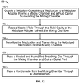
- a method described herein for delivering aerosolized medication combined with heated and humidified breathing gas includes coupling a nebulizer containing a medication to a nebulizer adapter having a mixing chamber and a fluid cavity surrounding the mixing chamber, passing a heated fluid through the fluid cavity of the nebulizer adapter to heat the mixing chamber, nebulizing the medication and transmitting the nebulized medication into the mixing chamber, passing a heated and humidified breathing gas through the mixing chamber and out an outlet port, and passing a condensate from the mixing chamber through a drain port.
- the method of further includes passing the condensate into an evaporative dispersal system.
- the method further comprises passing the condensate into a condensate trap.
- the method further includes passing the condensate through a glass filter into an absorbent pad.
- the method further includes removing the nebulizer from the nebulizer adapter, and inserting a plug into the nebulizer adapter to fill most of the mixing chamber. In certain examples, the method further includes removing the nebulizer from the nebulizer adapter, and inflating a balloon to fill most of the mixing chamber. In certain examples, the method further includes circulating the fluid in the fluid cavity. The method may further include connecting the outlet port to a nasal cannula.
- a nebulizer adapter in another aspect, includes means for releasably receiving a nebulizer and having mixing means for mixing a heated and humidified breathing gas with a nebulized medication and heating means for heating the mixing means using a fluid, means for delivering a fluid to the heating means, means for delivering heated and humidified breathing gas to the mixing means, means for passing a mixed gas out of the mixing means, and means for draining condensate from the mixing means.
- the means for fluidly connecting the fluid to the heating means is concentric with the means for delivering heated and humidified breathing gas to the mixing means.
- the nebulizer adapter further includes means for passing the condensate into an evaporative dispersal system.
- the nebulizer adapter may further include means for passing the condensate into a condensate trap.
- the nebulizer adapter may further include means for passing the condensate through a glass filter into an absorbent pad.
- the nebulizer adapter may further include means for plugging the nebulizer adapter to fill most of the mixing chamber.
- the nebulizer adapter further includes means for inflating a balloon to fill most of the mixing chamber. In certain implementations, the nebulizer adapter further includes means for circulating the fluid in the fluid cavity. In certain implementations, the nebulizer adapter further includes means for connecting a nasal cannula to the means for passing a mixed gas out of the mixing means.
- the systems, devices and methods described herein provide a nebulizer adapter that allows simultaneous administration of nebulized drugs and respiratory therapy.
- the nebulizer adapter addresses potential complications caused by condensation in the ventilation circuit by reducing risk of condensation and providing devices that remove condensate that does collect during therapy.
- the nebulizer adapter reduces the rate of condensation by reducing cooling due to heat loss to the ambient environment and by reducing cooling due to gas expansion when breathing gas enters a mixing chamber of the adapter in which heated and humidified breathing gas is mixed with nebulized medication.
- the nebulizer adapter reduces heat loss from the mixing chamber by circulating a heating fluid through a fluid cavity surrounding the mixing chamber.
- the nebulizer adapter is configured to receive a plug that reduces the available volume of the mixing chamber.
- the nebulizer adapter also manages condensate that does collect through use of one or more moisture removal systems including evaporative dispersal systems, absorbent pads, or condensate traps.
- the design of the nebulizer adapter also facilitates the use of single-dose nebulizers.
- Single-dose nebulizers reduce the risk of contaminating the ventilation circuit compared to reusable nebulizers.
- the mixing chamber is heated by a fluid cavity in the nebulizer adapter instead of in the nebulizer itself, modifications to the nebulizer are not required for use with the present system. This reduces the number of parts needed to incorporate the nebulizer, and when the nebulizer is removed and replaced, a heating fluid connection does not have to be disconnected from the nebulizer. Instead, the heating fluid remains continuously connected to the nebulizer adapter. This design allows heating fluid to be continuously circulated and reduces the risk of spilling or contaminating heating fluid in the circuit.
- the design of the nebulizer adapter also provides connection to a multi-lumen ventilation circuit. For instance, if the ventilation circuit carries both breathing gas and heating fluid in a single delivery tube with multiple lumens, that delivery tube may be connected to the nebulizer adapter at a single point. This single connection point reduces the bulk of the connection between the adapter and the ventilation circuit by reducing the number of connections and tubing adapters needed compared to an adapter or nebulizer having separate ports for breathing gas and heating connections.
- FIG. 1 shows a nebulizer adapter for use in a respiratory therapy circuit.
- the nebulizer adapter 100 includes a cup 102 configured to receive a nebulizer through an opening 101 of the adapter.
- the cup 102 has an interior wall 104 that defines a gas mixing chamber 106 and an exterior wall 108.
- a fluid cavity 110 is disposed between the interior wall 104 and the exterior wall 108.
- a heating fluid is delivered to and circulated in the fluid cavity 110 to heat the gas mixing chamber 106.
- the nebulizer adapter 100 also includes an inlet port 112 connected to the cup 102.
- the inlet port 112 has a fluid lumen 114 and a breathing gas lumen 116.
- the fluid lumen 114 is in fluid communication with the fluid cavity 110 and enables a heating fluid to be delivered to the fluid cavity 110.
- the breathing gas lumen 116 is in fluid communication with the mixing chamber 106 and allows breathing gas to be delivered to the gas mixing chamber 106.
- the breathing gas may be a heated and humidified gas and have high oxygen content. In certain embodiments, breathing gas is passed into the breathing gas lumen at a rate of between eight and forty liters per minute, though any suitable flow rate may be used for a particular therapy or application.
- the breathing gas lumen 116 is concentric with the fluid lumen 114, and thus both heating fluid and breathing gas can be delivered to the nebulizer adapter from a delivery tube at a single connection point. Having a single point of connection to a single delivery tube allows for simpler and more compact attachment (e.g., fewer tubes and connectors) compared to systems with separate delivery tubes for breathing gas and heating fluid.
- the nebulizer adapter 100 also includes an outlet 118 and a drain port 119, both of which are in fluid communication with the gas mixing chamber 106.
- the outlet 118 passes breathing gas that has been mixed with nebulized medication from the mixing chamber 106.
- the nebulizer adapter 100 may be located proximate to the patient, in which case the outlet port 118 may be connected to a nasal cannula, or the nebulizer adapter may be located proximate to the source of heated and humidified breathing gas.
- the gas exiting the gas mixing chamber 106 through outlet 118 may be connected to a delivery tube carrying a heated fluid to reduce condensation as discussed below in relation to FIG. 8 .
- the drain port 119 on nebulizer adapter 100 removes condensate from the mixing chamber 106.
- Condensate can form in the mixing chamber 106 due to cooling of the heated and humidified breathing gas. Condensation is a particular concern for HFT because HFT devices supply breathing gas with a high relative humidity and a high temperature. If condensate is not managed, it can flood a patient's nasal passages or collect and stagnate in the ventilation circuit which presents a biologic hazard to the patient. The collection of condensation can prevent continuous use of therapy, because therapy may be interrupted periodically for removal of condensate. To address these challenges, the nebulizer adapter 100 continuously eliminates condensate through the drain port 119.
- the drain port 119 is located at the bottom of the cup 102 such that gravity draws the condensate to the drain port 119. Pressure in the gas mixing chamber 106 also forces the condensate through drain port 119. Drain port 119 may pass condensate to an evaporative dispersal system, an absorbent pad, a condensate trap or another suitable device to remove moisture.
- the drain port 119 may be a small aperture to reduce the risk of substantial loss of breathing gas flow. A small aperture also reduces the risk of introduction of outside contaminants through the drain port 119 into the mixing chamber 106.
- FIG. 1 shows the nebulizer adapter without a nebulizer
- a nebulizer is inserted into cup 102 as shown in FIG. 2.
- FIG. 2 shows the nebulizer adapter 100 of FIG. 1 coupled to a nebulizer 120.
- the nebulizer 120 slides through opening 101 into the gas mixing chamber 106 defined by interior wall 104.
- the outer wall of nebulizer 120 engages in an interference fit with interior wall 104.
- the nebulizer 120 may be a vibrating mesh nebulizer, an ultrasonic nebulizer (e.g., a nebulizer with a vibrating piezocrystal), a jet nebulizer, or any other suitable type of nebulizer. Also, the nebulizer 120 may be a single-dose nebulizer or a reusable nebulizer. The nebulizer 120 dispenses nebulized medication into mixing chamber 106 through one or more openings on bottom face 122 of the nebulizer 120. As used herein, the term nebulized is understood to also include aerosolized or atomized medication. Nebulized medications may include a respiratory medication, such as a bronchodilator.
- the nebulized medication mixes with heated and humidified breathing gas that is passed into the mixing chamber through a nozzle 117, and the breathing gas mixed with nebulized medication is then passed out of outlet 118.
- condensation may occur due to cooling.
- the condensation is undesirable because condensate could limit the gas flow through the system, present a biologic hazard to the patient, or could potentially flow into a nasal cannula and enter a patient's nasal passage. Condensation is a particular concern for HFT because HFT devices supply breathing gas at a high flow rate.
- HFT provides a high flow of gas with a high relative humidity and a high temperature.
- the heating and humidifying of the breathing gas used in HFT is beneficial because high flow rates of dry breathing gas leads to patient discomfort (e.g., due to drying of nasal passages).
- heated and humidified gas cools, some of the moisture carried in the breathing gas cannot remain soluble and condenses. With the high flow rate of HFT, there is a substantial amount of moisture in the breathing circuit that could potentially become condensate if the gas cools. Cooling of the heated and humidified gas can occur due to expansion of the gas as it exits nozzle 117 and enters the gas mixing chamber 106. Cooling can also occur due to heat loss to the ambient environment (e.g., radiative cooling at the plastic walls of the adapter).
- the circulation of heated fluid in fluid cavity 110 reduces the cooling relative to an uninsulated nebulizer adapter.
- the heating fluid entering the fluid cavity has a temperature of about 43 degrees Celsius and the breathing gas entering the mixing chamber may have a temperature of about 35 to 43 degrees.
- the breathing gas is insulated and heated by the heating fluid to counteract cooling due to gas expansion.
- the circulation of the heating fluid increases the convective heat transfer rate between the gas mixing chamber 106 and the fluid in the fluid cavity 110 relative to still water. Circulation of the heating fluid also allows the fluid to continuously deliver heat to the gas in the mixing chamber 106 while being continuously reheated at a heating unit (not shown) elsewhere in the circuit.
- the decreased cooling of the breathing gas due to the heating fluid reduces the rate of condensation in mixing chamber 106.
- FIG. 3 A perspective view of the nebulizer adapter 100 of FIG. 1 with arrows 206 showing the path of the circulating heating fluid is shown in FIG. 3 .
- FIG. 4 shows a corresponding top view with the nebulizer 120 removed to show another view of the path of fluid flow through the fluid cavity 110.
- the direction of circulation of heating fluid in both figures is indicated by arrows 206, and the direction of the flow of breathing gas is shown by arrows 202 and 204.
- the inlet port 112 has three passages for fluid and gas: a fluid inflow passage 114a, a fluid outflow passage 114b, and a breathing gas lumen 116.
- the use of two fluid passages allows heating fluid to pass into and out of the fluid cavity 110, while the additional gas lumen allows for separate transport of heated and humidified breathing gas.
- Heating fluid enters fluid inflow passage 114a and provides thermal insulation within 110 before returning through fluid outflow passage 114b.
- Internal walls of the fluid cavity 110 direct the heated fluid from fluid inflow passage 114a, around the periphery of the fluid cavity 110, before exiting through the fluid outflow passage 114b.
- the circulation of the heating fluid allows heat to be continuously supplied to fluid cavity 110.
- heated fluid flows in a closed circuit so that the heating fluid is continuously recycled and reheated as necessary by a high flow therapy unit (not shown).
- the fluid circulating within fluid cavity 110 in turn, insulates the breathing gas and nebulized medication in the gas mixing chamber. After mixing, the breathing gas mixed with nebulized medication exits outlet 118.
- FIG. 5 shows a cross section taken along section line A-A of the nebulizer adapter of FIG. 4 .
- the cross-section shows that the breathing gas lumen 116 is concentric with a fluid lumen defined by the fluid inflow passage 114a and the fluid outflow passage 114b, which are separated by divider 210.
- the breathing gas is insulated from ambient air and maintained at a temperature above the ambient temperature, thus reducing condensation.
- the concentric fluid lumen and breathing gas lumen may simplify connection to delivery tubing by minimizing the number of separate attachment points.
- FIG. 4 shows a single lumen outlet 118
- the adapter outlet may have two or more output lumens to pass both breathing gas and heating fluid downstream in the ventilation circuit.
- FIG. 6 shows a top view of a nebulizer adapter 700 with the nebulizer removed to show the path of fluid flow through the fluid cavity 710.
- the outlet 718 of the nebulizer adapter 700 has two lumens, an outflow fluid lumen 732 and an outflow gas lumen 730.
- the outflow fluid lumen 732 is in fluid communication with fluid cavity 710
- the outflow gas lumen 730 is in fluid communication with the gas mixing chamber 706.
- heating fluid that is passed into fluid cavity 710 can be further passed into tubing that carries the breathing gas mixed with nebulized medication out of the mixing chamber 706.
- the outflow fluid lumen 732 surrounds the outflow gas lumen 730, and the heating fluid passed through the outflow fluid lumen 732 insulates and warms the breathing gas exiting the mixing chamber 706.
- the outflow fluid lumen 732 may be divided into two passages, a first passage 732a carrying heating fluid exiting fluid cavity 710 and a second passage 732b carrying heating fluid returning to fluid cavity 710.
- the insulation and heat provided by the heating fluid in the outflow fluid lumen 732 reduces condensation of moisture in the breathing gas on its way to the patient.
- Such a configuration may be desirable in instances where the nebulizer is located in a breathing circuit and away from the patient (e.g., when the nebulizer adapter is proximate to the source of the heated and humidified breathing gas).
- FIG. 7 shows the nebulizer adapter of FIG. 1 with a volume filling plug 300 aligned to be inserted into mixing chamber 106 in place of a nebulizer.
- the volume-filling plug 300 has a cylindrical body 304 that mates with interior wall 104.
- the cylindrical body 304 may form an interference fit with interior wall 104 that serves to hold the volume-filling plug firmly in position, while also sealing the mixing chamber 106 to prevent the escape of breathing gas.
- Insertion of the plug 300 into the mixing chamber 106 is limited by a flange 302 which makes contact with the upper surface 107 of the cup 102.
- the flange 302 may also form a seal with the upper surface 107 of the cup 102 to reduce the risk of gas leaking out of the mixing chamber 106.
- the volume-filling plug 300 may be inserted into the mixing chamber 106 until the bottom surface of plug 306 engages the bottom surface 109 of interior wall 104.
- the volume-filling plug 300 has a protrusion 306 which mates with nozzle 117 so that when the volume-filling plug 300 is fully inserted into the mixing chamber 106, the protrusion 306 extends over both sides of nozzle 117.
- a balloon is used in place of the volume-filling plug.
- a balloon may be built into the cup 102 and inflated with saline or air when the nebulizer 120 is not inserted. Such a balloon may subsequently be deflated before reinsertion of the nebulizer 120.
- FIG. 8 shows the nebulizer adapter 100 of FIG. 1 coupled with an evaporative dispersal system according to certain embodiments.
- the evaporative dispersal system 400 is shown on a nebulizer adapter that has an outflow fluid lumen at its outlet, it may also be preferable to use the evaporative dispersal system 400 in embodiments in which the nebulizer adapter is proximal to the patient.
- the evaporative dispersal system 400 is connected to the drain port 119 of nebulizer adapter 100.
- the connection to drain port 119 can be permanent and may be held using an adhesive, ultrasonic weld, or another suitable permanent attachment mechanism. Alternatively, the connection to drain port 119 may be temporary and may be held by a positive attachment mechanism (e.g., a Luer lock) or an interference fit.
- the evaporative dispersal system 400 is mounted on delivery tubing 420 which is connected to the inlet port 112. Condensate 121 that collects in cup 102 may be forced by gas pressure in mixing chamber 106 to flow through drain port 119 into the evaporative dispersal system.
- the condensate may be driven by capillary action from a region 400a proximal to the drain port 119 towards a region 400b distal to the drain port 119. As the condensate is wicked along the length of evaporative dispersal system 400, it also evaporates into ambient air.
- FIG. 9 A cross section of the evaporative dispersal system 400 is shown in FIG. 9 .
- the evaporative dispersal system is supported by the wall 402 of the delivery tubing 420 and includes a frame 404, a wicking layer 406 covering the frame 404, and a semi-permeable bacteriostatic layer 408 covering the wicking material 406.
- the frame 404 may be fused to the delivery tube 420 or bonded temporarily.
- the semi-permeable bacteriostatic layer 408 is affixed to the plastic frame 404.
- the gap between the inner surface of the semi-permeable bacteriostatic layer 408 and the outer surface of the plastic frame is filled with the wicking material 406.
- the wicking material 406 promotes the mobilization of condensate down the length of the evaporative device.
- the wicking material 406 may be biocompatible and water insoluble.
- the wicking material is a hydrocarbon.
- a hydrocarbon wicking material may allow diffusion of the condensate while prohibiting significant microbiological contamination from reentering the closed system.
- FIG. 10 shows the nebulizer adapter 100 of FIG. 1 placed over an absorbent pad 504. For simplicity, neither the nebulizer adapter nor the volume-filling plug is shown inserted in cup 102.
- Condensate 121 that collects in gas mixing chamber 106 exits mixing chamber 106 through drain port 119 and is passed through a filter 502. The filter allows the condensate 121 to seep through and pass into the absorbent pad 504.
- the filter 502 is a glass filter with an average pore diameter pore of less than 0.5 ⁇ m.
- the glass filter allows smooth dispersal of the condensate while also keeping outside contaminants from entering the ventilation circuit through the drain port. Pressure inside the mixing chamber 106 can cause condensate exiting the chamber to spray, often with a whistling sound, out of the chamber.
- the glass filter provides for quite dispersal of the condensate in a liquid state to be soaked up by the absorbent pad 504.
- the filter also serves as a contamination shield, reducing the risk of bacteria entering the mixing chamber 106.
- the absorbent pad 504 may be placed on a patient's chest such that the bottom surface 508 rests on the patient's chest, while the upper surface 506 is exposed so that condensate 121 exiting filter 502 may be absorbed.
- FIG. 11 shows the nebulizer adapter of FIG. 1 coupled with a condensate trap 610.
- Condensate trap 610 is connected to the drain port 119 on cup 102 via tubing 612. Flow of the condensate 121 into the tubing 612 may be facilitated by the positive pressure inside mixing chamber 106 relative to the pressure inside the condensate trap 610.
- a pressure differential between the mixing chamber 106 and the inside of the condensate trap 618 may be achieved due to a vented filter 618 on the condensate trap 610 which allows the pressure in the interior 622 of condensate trap 610 to be closer to atmosphere pressure.
- the filter material for the vented filter 618 may be hydrophobic to prevent the rapid outflow of trapped condensate 616 from the condensate trap 610.
- the tubing 612 is connected to the condensate trap via connector 614, which may provide a permanent attachment or a reversible positive locking mechanism (e.g., Luer lock).
- a reversible positive locking mechanism may facilitate replacement of the condensate trap.
- the lid of the condensate trap 610 may be removable for emptying the condensate trap 610.
- the condensate trap 610 is depicted as about the same size as cup 102, in certain embodiments, condensate trap 610 has a capacity of 1 liter or more. In such embodiments, the condensate trap may be located on a stand included with the unit that supplies the heated and humidified breathing gas.
- FIG. 12 shows a method 150 for delivering aerosolized medication combined with heated and humidified breathing gas.
- the method outlined in flowchart 150 may be practiced using the nebulizer adapter 100 of FIGS. 1 and 2 . It will be understood by one of ordinary skill in the art that, prior to the steps shown in FIG. 12 , a heated and humidified breathing gas may be generated for delivery to a patient by any suitable means.
- a nebulizer containing a medication is coupled to a nebulizer adapter having a mixing chamber and a fluid cavity surrounding the mixing chamber.
- a heating fluid is passed through the fluid cavity of the nebulizer adapter to heat the mixing chamber. Heating the mixing chamber can reduce cooling of the breathing gas in the mixing chamber that can lead to condensation of moisture from the breathing gas. In certain embodiments, the heating fluid entering the fluid cavity has a temperature of about 43 degrees Celsius which is at or above the temperature of the breathing gas in the mixing chamber to facilitate heating of the breathing gas.
- step 156 the medication is nebulized and transmitted into the mixing chamber 106.
- step 158 a heated and humidified breathing gas is passed through the mixing chamber to entrain the nebulized medication in the flow of breathing gas.
- the breathing gas mixed with nebulized medication is passed out of an outlet port after mixing.
- the breathing gas has a temperature of about 35 to 43 degrees upon exiting the mixing chamber.
- Moisture from the heated and humidified breathing gas may condense in step 158 due to cooling effects such as expansive cooling and heat loss to the ambient environment. These cooling effects are mitigated by the heat and insulation provided by the heating fluid in the fluid cavity. If condensate forms despite the heating, the condensate is passed from the mixing chamber through a drain port in step 160.
- the condensate is passed through the drain port to an evaporative dispersal system, a condensate trap, an absorbent pad, or any other suitable moisture removing device.
- the nebulizer may be removed and a volume filling plug inserted.
- the volume filing plug reduces the expansion of the breathing gas as it passes through the mixing chamber and thus may reduce cooling associated with gas expansion. The reduction in cooling can lead to a reduction in condensation.
- FIG. 13 shows the nebulizer adapter of FIG. 1 in line with an HFT system according to certain embodiments.
- the nebulizer adapter 100 is connected to delivery tubing 420, water trap 610, nasal cannula 600, and nebulizer 120.
- the delivery tubing 420 connects to the inlet port 112 of the nebulizer adaptor 100.
- the other end of delivery tubing 420 is connected to a source of high flow heated and humidified breathing gas (not shown).
- the delivery tubing 420 delivers both heating fluid and heated and humidified breathing gas through at least two separate lumens.
- the heating fluid delivered by delivery tubing 420 enters the fluid cavity in nebulizer adapter 100, while the heated and humidified breathing gas enters the gas mixing chamber.
- the nasal cannula 600 is connected to the outlet 118 of the nebulizer adapter 100 via connector 602 so that the interior of tubing 603 is in fluid communication with the gas mixing chamber inside nebulizer adapter 100. Heated and humidified gas mixed with nebulized medication exits outlet 118, travels through tubing 630, and exits out of opening 604 in the nasal cannula 600.
- the cannula 600 is sized for use with infants, but any other suitable nasal cannula may be used. When the nasal cannula 600 is worn by a patient, openings 604 may be inserted into the patient's nostrils so that the heated and humidified breathing gas mixed with nebulized medication may be injected into a patient's nasal passages.
Landscapes
- Health & Medical Sciences (AREA)
- Life Sciences & Earth Sciences (AREA)
- General Health & Medical Sciences (AREA)
- Engineering & Computer Science (AREA)
- Anesthesiology (AREA)
- Biomedical Technology (AREA)
- Heart & Thoracic Surgery (AREA)
- Veterinary Medicine (AREA)
- Hematology (AREA)
- Animal Behavior & Ethology (AREA)
- Public Health (AREA)
- Pulmonology (AREA)
- Emergency Medicine (AREA)
- Infusion, Injection, And Reservoir Apparatuses (AREA)
- Pharmaceuticals Containing Other Organic And Inorganic Compounds (AREA)
- Otolaryngology (AREA)
- Respiratory Apparatuses And Protective Means (AREA)
Description
- Patients with respiratory ailments may be treated with respiratory assist devices, for example devices that deliver supplemental breathing gas to a patient. Such devices include devices that deliver gas to a patient using high flow therapy (HFT). HFT devices deliver a high flow rate of breathing gas to a patient via a nasal cannula to increase a patient's fraction of inspired oxygen (Fi02) while decreasing a patient's work of breathing. Some HFT devices heat and humidify the delivered breathing gas to reduce patient discomfort.
- Patients receiving respiratory therapy may also benefit from administration of nebulized medications. Nebulizers allow aerosolized respiratory medications, such as bronchodilators (e.g., Albuterol (Ventolin), Salbutamol (Proventil), Levosalbutamol/Levalbuterol (Xopenex)) for treating asthma or Chronic Obstructive Pulmonary Disease (COPD) to be administered through inhalation directly to a patient's lungs. Nebulizers may be connected to respiratory assist devices to supply nebulized medication together with supplemental breathing gas. Such systems can allow a patient to receive the medication without stopping use of a respiratory assist device.
- A combination of nebulized medication and HFT can be used to assist patients experiencing respiratory distress and provide a comfortable and effective management of cardiopulmonary conditions. A challenge associated with delivering nebulized medication via a high- flow system is condensation of moisture from the mixture of heated and humidified breathing gas and nebulized medication. Condensation in a ventilation circuit presents both clinical and mechanical challenges, as the condensate can build up to limit flow through the system and also collect and stagnate which presents a biologic hazard to the patient.
-
US2005/217667 describes a multipurpose aerosol medication delivery apparatus that includes a holding chamber for use with a metered dosed inhaler and/or a nebulizer.US3945378 describes a positive pressure breathing circuit for operation in conjunction with a positive pressure ventilator and interposed between the ventilator and a patient-supported device for respiratory therapy.WO2005/115520 describes the pulmonary delivery of an aerosolized active agent to a patient in need of respiratory treatment.WO 2010/091259 A2 discloses a nebulizer assembly including a reservoir and a nebulizer for producing an aerosolized gas, and a breathing gas mixing chamber coupled to an outlet port of the nebulizer to entrain nebulized medication into a breathing gas.WO2010/035251 A2 discloses a supplemental oxygen delivery system in which aerosol is delivered into a housing sitting in a breathing circuit, such that the supplemental oxygen passes through the chamber and collects the aerosol transporting it to a patient. - The invention is defined by the subject-matter of
claim 1. Preferred embodiments are defined in the dependent claims. Disclosed herein are systems, devices, and methods for heating nebulizer adapters used in respiratory therapy. In certain implementations, the systems, devices, and methods include a nebulizer adapter with a gas mixing chamber surrounded by a fluid cavity. Nebulized medication is mixed with heated and humidified breathing gas in the gas mixing chamber. Heating fluid is passed into the fluid cavity to heat the gas mixing chamber, thereby reducing condensation of moisture from the heated and humidified breathing gas. Condensate that does collect in the gas mixing chamber is drained through a drain port. The drain port may pass the condensate into an evaporative dispersal system, a condensate trap, an absorbent pad, or any other suitable moisture removing device. These systems devices and methods provide an effective method for reducing unwanted condensation in the ventilation circuit and for managing condensation that does occur, thereby enabling continuous or semi-continuous operation of high flow therapy (HFT) with nebulized medication. Furthermore, by locating the fluid cavity in the nebulizer adapter rather than in the nebulizer itself, a simpler nebulizer may be used which may facilitate the use of single-dose nebulizers. - The nebulizer adapter disclosed herein can be used with a wide range of nebulizers, including vibrating mesh nebulizers (e.g., the AERONEB® nebulizer), ultrasonic nebulizers (e.g., nebulizers with a vibrating piezocrystal), nebulizers using compressed gases, jet nebulizers, single-dose nebulizers, or reusable nebulizers. In a preferred embodiment, the nebulizer adapter is used with HFT, but the nebulizer adapter may also be used with other types of respiratory therapy and respiratory therapy devices, including low flow oxygen therapy, continuous positive airway pressure therapy (CPAP), mechanical ventilation, oxygen masks, Venturi masks, and tracheotomy masks.
- In one aspect, a nebulizer adapter includes a cup having an interior wall defining a gas mixing chamber, an exterior wall, and a fluid cavity disposed between the interior wall and the exterior wall. The nebulizer adapter also includes an inlet port having a fluid lumen in fluid communication with the fluid cavity and a breathing gas inlet lumen in fluid communication with the mixing chamber, an outlet having a breathing gas outlet lumen, and a drain port in fluid communication with the mixing chamber and having a drain lumen that passes from the interior wall to the exterior wall of the cup. In certain implementations, the fluid lumen is concentric with the breathing gas inlet lumen.
- In certain implementations, the drain port is in fluid communication with an evaporative dispersal system. The evaporative dispersal system may include a frame, a wicking layer covering the frame, and a semipermeable bacteriostatic layer covering the wicking material. In certain implementations, a delivery tube is connected to the inlet port and the evaporative dispersal system is supported on an outer surface of the delivery tube along a length of the delivery tube configured to wick condensate from a first region proximal to the drain port towards a second region distal to the drain port. The wicking layer may be a water-insoluble biocompatible material. In certain implementations the wicking layer is a hydrocarbon.
- In certain implementations, the drain port is in fluid communication with a condensation trap. The drain port may be connected to a glass filter having an average pore diameter less than 0.5 microns and the glass filter is connected to an absorbent pad.
- In certain implementations, the nebulizer adapter includes a plug configured to substantially occlude the mixing chamber when the nebulizer is not attached to the cup. Alternatively, the nebulizer adapter may include an inflatable balloon configured to substantially occlude the mixing chamber when the nebulizer is not attached to the cup.
- In certain implementations, the fluid lumen of the inlet port comprises a divider for separating an inflow passage for carrying fluid to the cup and an outflow passage for carrying fluid away from the cup. The outlet port may be configured to connect to a nasal cannula. In certain implementations, the outflow port includes an outflow fluid lumen in fluid communication with the fluid cavity and an outflow breathing gas lumen in fluid communication with the mixing chamber. The outflow fluid lumen may be concentric with the outflow breathing gas lumen.
- A method described herein for delivering aerosolized medication combined with heated and humidified breathing gas includes coupling a nebulizer containing a medication to a nebulizer adapter having a mixing chamber and a fluid cavity surrounding the mixing chamber,
passing a heated fluid through the fluid cavity of the nebulizer adapter to heat the mixing chamber, nebulizing the medication and transmitting the nebulized medication into the mixing chamber, passing a heated and humidified breathing gas through the mixing chamber and out an outlet port, and passing a condensate from the mixing chamber through a drain port. In certain examples, the method of further includes passing the condensate into an evaporative dispersal system. In certain examples, the method further comprises passing the condensate into a condensate trap. In certain examples, the method further includes passing the condensate through a glass filter into an absorbent pad. - In certain examples, the method further includes removing the nebulizer from the nebulizer adapter, and inserting a plug into the nebulizer adapter to fill most of the mixing chamber. In certain examples, the method further includes removing the nebulizer from the nebulizer adapter, and inflating a balloon to fill most of the mixing chamber. In certain examples, the method further includes circulating the fluid in the fluid cavity. The method may further include connecting the outlet port to a nasal cannula.
- In another aspect, a nebulizer adapter includes means for releasably receiving a nebulizer and having mixing means for mixing a heated and humidified breathing gas with a nebulized medication and heating means for heating the mixing means using a fluid, means for delivering a fluid to the heating means, means for delivering heated and humidified breathing gas to the mixing means, means for passing a mixed gas out of the mixing means, and means for draining condensate from the mixing means. In certain implementations, the means for fluidly connecting the fluid to the heating means is concentric with the means for delivering heated and humidified breathing gas to the mixing means.
- In certain implementations, the nebulizer adapter further includes means for passing the condensate into an evaporative dispersal system. The nebulizer adapter may further include means for passing the condensate into a condensate trap. The nebulizer adapter may further include means for passing the condensate through a glass filter into an absorbent pad. The nebulizer adapter may further include means for plugging the nebulizer adapter to fill most of the mixing chamber.
- In certain implementations, the nebulizer adapter further includes means for inflating a balloon to fill most of the mixing chamber. In certain implementations, the nebulizer adapter further includes means for circulating the fluid in the fluid cavity. In certain implementations, the nebulizer adapter further includes means for connecting a nasal cannula to the means for passing a mixed gas out of the mixing means.
- The foregoing and other objects and advantages will be apparent upon consideration of the following detailed description, taken in conjunction with the accompanying drawings, in which like reference characters refer to like parts throughout, and in which:
-
FIG. 1 shows an illustrative nebulizer adapter; -
FIG. 2 shows the nebulizer adapter ofFIG. 1 coupled to a nebulizer; -
FIG. 3 shows the nebulizer adapter ofFIG. 1 with heating fluid circulating in the adapter; -
FIG. 4 shows a top view of the nebulizer adapter ofFIG. 1 with heating fluid circulating in the adapter; -
FIG. 5 shows a cross section taken along section line A-A of the nebulizer adapter inFIG. 5 ; -
FIG. 6 shows a top view of an illustrative nebulizer adapter with heating fluid circulating in the adapter; -
FIG. 7 shows the illustrative nebulizer adapter ofFIG. 1 coupled to a volume filling plug; -
FIG. 8 shows the nebulizer adapter ofFIG. 1 with an evaporative dispersal system; -
FIG. 9 shows a cross section of the evaporative dispersal system ofFIG. 8 ; -
FIG. 10 shows the nebulizer adapter ofFIG. 1 and an absorbent pad; -
FIG. 11 shows the nebulizer adapter ofFIG. 1 coupled with a condensate trap; -
FIG. 12 shows an illustrative process for delivering aerosolized medication combined with heated and humidified breathing gas; and -
FIG. 13 shows the nebulizer adapter ofFIG. 1 in line with a high flow therapy system. - To provide an overall understanding of the systems, devices, and methods described herein, certain illustrative embodiments and examples will be described. Although the embodiments and features described herein are specifically described for use in connection with a high flow therapy system, it will be understood that all the components and other features outlined below may be combined with one another in any suitable manner and may be adapted and applied to other types of respiratory therapy and respiratory therapy devices, including low flow oxygen therapy, continuous positive airway pressure therapy (CPAP), mechanical ventilation, oxygen masks, Venturi masks, and tracheotomy masks.
- The systems, devices and methods described herein provide a nebulizer adapter that allows simultaneous administration of nebulized drugs and respiratory therapy. The nebulizer adapter addresses potential complications caused by condensation in the ventilation circuit by reducing risk of condensation and providing devices that remove condensate that does collect during therapy. The nebulizer adapter reduces the rate of condensation by reducing cooling due to heat loss to the ambient environment and by reducing cooling due to gas expansion when breathing gas enters a mixing chamber of the adapter in which heated and humidified breathing gas is mixed with nebulized medication. In particular, the nebulizer adapter reduces heat loss from the mixing chamber by circulating a heating fluid through a fluid cavity surrounding the mixing chamber. To reduce cooling due to gas expansion when a nebulizer is not coupled to the nebulizer adapter, the nebulizer adapter is configured to receive a plug that reduces the available volume of the mixing chamber. In addition to reducing the rate of condensation, the nebulizer adapter also manages condensate that does collect through use of one or more moisture removal systems including evaporative dispersal systems, absorbent pads, or condensate traps.
- The design of the nebulizer adapter also facilitates the use of single-dose nebulizers. Single-dose nebulizers reduce the risk of contaminating the ventilation circuit compared to reusable nebulizers. Because the mixing chamber is heated by a fluid cavity in the nebulizer adapter instead of in the nebulizer itself, modifications to the nebulizer are not required for use with the present system. This reduces the number of parts needed to incorporate the nebulizer, and when the nebulizer is removed and replaced, a heating fluid connection does not have to be disconnected from the nebulizer. Instead, the heating fluid remains continuously connected to the nebulizer adapter. This design allows heating fluid to be continuously circulated and reduces the risk of spilling or contaminating heating fluid in the circuit.
- The design of the nebulizer adapter also provides connection to a multi-lumen ventilation circuit. For instance, if the ventilation circuit carries both breathing gas and heating fluid in a single delivery tube with multiple lumens, that delivery tube may be connected to the nebulizer adapter at a single point. This single connection point reduces the bulk of the connection between the adapter and the ventilation circuit by reducing the number of connections and tubing adapters needed compared to an adapter or nebulizer having separate ports for breathing gas and heating connections.
-
FIG. 1 shows a nebulizer adapter for use in a respiratory therapy circuit. Thenebulizer adapter 100 includes acup 102 configured to receive a nebulizer through anopening 101 of the adapter. Thecup 102 has aninterior wall 104 that defines agas mixing chamber 106 and anexterior wall 108. Afluid cavity 110 is disposed between theinterior wall 104 and theexterior wall 108. A heating fluid is delivered to and circulated in thefluid cavity 110 to heat thegas mixing chamber 106. - The
nebulizer adapter 100 also includes aninlet port 112 connected to thecup 102. Theinlet port 112 has afluid lumen 114 and abreathing gas lumen 116. Thefluid lumen 114 is in fluid communication with thefluid cavity 110 and enables a heating fluid to be delivered to thefluid cavity 110. Thebreathing gas lumen 116 is in fluid communication with the mixingchamber 106 and allows breathing gas to be delivered to thegas mixing chamber 106. The breathing gas may be a heated and humidified gas and have high oxygen content. In certain embodiments, breathing gas is passed into the breathing gas lumen at a rate of between eight and forty liters per minute, though any suitable flow rate may be used for a particular therapy or application. Thebreathing gas lumen 116 is concentric with thefluid lumen 114, and thus both heating fluid and breathing gas can be delivered to the nebulizer adapter from a delivery tube at a single connection point. Having a single point of connection to a single delivery tube allows for simpler and more compact attachment (e.g., fewer tubes and connectors) compared to systems with separate delivery tubes for breathing gas and heating fluid. - The
nebulizer adapter 100 also includes anoutlet 118 and adrain port 119, both of which are in fluid communication with thegas mixing chamber 106. Theoutlet 118 passes breathing gas that has been mixed with nebulized medication from the mixingchamber 106. Thenebulizer adapter 100 may be located proximate to the patient, in which case theoutlet port 118 may be connected to a nasal cannula, or the nebulizer adapter may be located proximate to the source of heated and humidified breathing gas. In such a configuration, the gas exiting thegas mixing chamber 106 throughoutlet 118 may be connected to a delivery tube carrying a heated fluid to reduce condensation as discussed below in relation toFIG. 8 . - The
drain port 119 onnebulizer adapter 100 removes condensate from the mixingchamber 106. Condensate can form in the mixingchamber 106 due to cooling of the heated and humidified breathing gas. Condensation is a particular concern for HFT because HFT devices supply breathing gas with a high relative humidity and a high temperature. If condensate is not managed, it can flood a patient's nasal passages or collect and stagnate in the ventilation circuit which presents a biologic hazard to the patient. The collection of condensation can prevent continuous use of therapy, because therapy may be interrupted periodically for removal of condensate. To address these challenges, thenebulizer adapter 100 continuously eliminates condensate through thedrain port 119. Thedrain port 119 is located at the bottom of thecup 102 such that gravity draws the condensate to thedrain port 119. Pressure in thegas mixing chamber 106 also forces the condensate throughdrain port 119.Drain port 119 may pass condensate to an evaporative dispersal system, an absorbent pad, a condensate trap or another suitable device to remove moisture. Thedrain port 119 may be a small aperture to reduce the risk of substantial loss of breathing gas flow. A small aperture also reduces the risk of introduction of outside contaminants through thedrain port 119 into the mixingchamber 106. - While
FIG. 1 shows the nebulizer adapter without a nebulizer, in use a nebulizer is inserted intocup 102 as shown inFIG. 2. FIG. 2 shows thenebulizer adapter 100 ofFIG. 1 coupled to anebulizer 120. Thenebulizer 120 slides throughopening 101 into thegas mixing chamber 106 defined byinterior wall 104. The outer wall ofnebulizer 120 engages in an interference fit withinterior wall 104. Thenebulizer 120 may be a vibrating mesh nebulizer, an ultrasonic nebulizer (e.g., a nebulizer with a vibrating piezocrystal), a jet nebulizer, or any other suitable type of nebulizer. Also, thenebulizer 120 may be a single-dose nebulizer or a reusable nebulizer. Thenebulizer 120 dispenses nebulized medication into mixingchamber 106 through one or more openings onbottom face 122 of thenebulizer 120. As used herein, the term nebulized is understood to also include aerosolized or atomized medication. Nebulized medications may include a respiratory medication, such as a bronchodilator. - The nebulized medication mixes with heated and humidified breathing gas that is passed into the mixing chamber through a
nozzle 117, and the breathing gas mixed with nebulized medication is then passed out ofoutlet 118. When the heated and humidified gas is introduced into mixingchamber 106, condensation may occur due to cooling. The condensation is undesirable because condensate could limit the gas flow through the system, present a biologic hazard to the patient, or could potentially flow into a nasal cannula and enter a patient's nasal passage. Condensation is a particular concern for HFT because HFT devices supply breathing gas at a high flow rate. When the breathing gas is pre-heated and humidified for patient comfort, HFT provides a high flow of gas with a high relative humidity and a high temperature. The heating and humidifying of the breathing gas used in HFT is beneficial because high flow rates of dry breathing gas leads to patient discomfort (e.g., due to drying of nasal passages). When heated and humidified gas cools, some of the moisture carried in the breathing gas cannot remain soluble and condenses. With the high flow rate of HFT, there is a substantial amount of moisture in the breathing circuit that could potentially become condensate if the gas cools. Cooling of the heated and humidified gas can occur due to expansion of the gas as it exitsnozzle 117 and enters thegas mixing chamber 106. Cooling can also occur due to heat loss to the ambient environment (e.g., radiative cooling at the plastic walls of the adapter). - The circulation of heated fluid in
fluid cavity 110 reduces the cooling relative to an uninsulated nebulizer adapter. In certain embodiments, the heating fluid entering the fluid cavity has a temperature of about 43 degrees Celsius and the breathing gas entering the mixing chamber may have a temperature of about 35 to 43 degrees. In such embodiments, the breathing gas is insulated and heated by the heating fluid to counteract cooling due to gas expansion. The circulation of the heating fluid increases the convective heat transfer rate between thegas mixing chamber 106 and the fluid in thefluid cavity 110 relative to still water. Circulation of the heating fluid also allows the fluid to continuously deliver heat to the gas in the mixingchamber 106 while being continuously reheated at a heating unit (not shown) elsewhere in the circuit. The decreased cooling of the breathing gas due to the heating fluid reduces the rate of condensation in mixingchamber 106. - A perspective view of the
nebulizer adapter 100 ofFIG. 1 witharrows 206 showing the path of the circulating heating fluid is shown inFIG. 3 .FIG. 4 shows a corresponding top view with thenebulizer 120 removed to show another view of the path of fluid flow through thefluid cavity 110. The direction of circulation of heating fluid in both figures is indicated byarrows 206, and the direction of the flow of breathing gas is shown byarrows - Referring to
FIG. 4 , theinlet port 112 has three passages for fluid and gas: afluid inflow passage 114a, afluid outflow passage 114b, and abreathing gas lumen 116. The use of two fluid passages allows heating fluid to pass into and out of thefluid cavity 110, while the additional gas lumen allows for separate transport of heated and humidified breathing gas. Heating fluid entersfluid inflow passage 114a and provides thermal insulation within 110 before returning throughfluid outflow passage 114b. Internal walls of thefluid cavity 110 direct the heated fluid fromfluid inflow passage 114a, around the periphery of thefluid cavity 110, before exiting through thefluid outflow passage 114b. Thus, the circulation of the heating fluid allows heat to be continuously supplied tofluid cavity 110. In certain embodiments, heated fluid flows in a closed circuit so that the heating fluid is continuously recycled and reheated as necessary by a high flow therapy unit (not shown). The fluid circulating withinfluid cavity 110, in turn, insulates the breathing gas and nebulized medication in the gas mixing chamber. After mixing, the breathing gas mixed with nebulized medication exitsoutlet 118. -
FIG. 5 shows a cross section taken along section line A-A of the nebulizer adapter ofFIG. 4 . The cross-section shows that thebreathing gas lumen 116 is concentric with a fluid lumen defined by thefluid inflow passage 114a and thefluid outflow passage 114b, which are separated bydivider 210. By surrounding thebreathing gas lumen 116 with the heated fluid, the breathing gas is insulated from ambient air and maintained at a temperature above the ambient temperature, thus reducing condensation. As discussed above, the concentric fluid lumen and breathing gas lumen may simplify connection to delivery tubing by minimizing the number of separate attachment points. - While the nebulizer adapter in
FIG. 4 . shows asingle lumen outlet 118, the adapter outlet may have two or more output lumens to pass both breathing gas and heating fluid downstream in the ventilation circuit.FIG. 6 shows a top view of anebulizer adapter 700 with the nebulizer removed to show the path of fluid flow through thefluid cavity 710. Theoutlet 718 of thenebulizer adapter 700 has two lumens, anoutflow fluid lumen 732 and anoutflow gas lumen 730. Theoutflow fluid lumen 732 is in fluid communication withfluid cavity 710, and theoutflow gas lumen 730 is in fluid communication with thegas mixing chamber 706. By providing afluid lumen 732 on the outlet, heating fluid that is passed intofluid cavity 710 can be further passed into tubing that carries the breathing gas mixed with nebulized medication out of the mixingchamber 706. Theoutflow fluid lumen 732 surrounds theoutflow gas lumen 730, and the heating fluid passed through theoutflow fluid lumen 732 insulates and warms the breathing gas exiting the mixingchamber 706. Theoutflow fluid lumen 732 may be divided into two passages, afirst passage 732a carrying heating fluid exitingfluid cavity 710 and asecond passage 732b carrying heating fluid returning tofluid cavity 710. The insulation and heat provided by the heating fluid in theoutflow fluid lumen 732 reduces condensation of moisture in the breathing gas on its way to the patient. Such a configuration may be desirable in instances where the nebulizer is located in a breathing circuit and away from the patient (e.g., when the nebulizer adapter is proximate to the source of the heated and humidified breathing gas). - While heating the mixing chamber as discussed above reduces cooling of the breathing gas due to heat loss to the ambient environment, cooling due to gas expansion can also be reduced by reducing the available volume of mixing
chamber 106 when a nebulizer is not being used.FIG. 7 shows the nebulizer adapter ofFIG. 1 with avolume filling plug 300
aligned to be inserted into mixingchamber 106 in place of a nebulizer. The volume-fillingplug 300 has acylindrical body 304 that mates withinterior wall 104. Thecylindrical body 304 may form an interference fit withinterior wall 104 that serves to hold the volume-filling plug firmly in position, while also sealing the mixingchamber 106 to prevent the escape of breathing gas. Insertion of theplug 300 into the mixingchamber 106 is limited by aflange 302 which makes contact with theupper surface 107 of thecup 102. Theflange 302 may also form a seal with theupper surface 107 of thecup 102 to reduce the risk of gas leaking out of the mixingchamber 106. Alternatively, the volume-fillingplug 300 may be inserted into the mixingchamber 106 until the bottom surface ofplug 306 engages thebottom surface 109 ofinterior wall 104. The volume-fillingplug 300 has aprotrusion 306 which mates withnozzle 117 so that when the volume-fillingplug 300 is fully inserted into the mixingchamber 106, theprotrusion 306 extends over both sides ofnozzle 117. The mating fit thus reduces the expansion of the breathing gas that passes through the adapter, while not blocking the flow of that breathing gas. In certain embodiments, a balloon is used in place of the volume-filling plug. For example, a balloon may be built into thecup 102 and inflated with saline or air when thenebulizer 120 is not inserted. Such a balloon may subsequently be deflated before reinsertion of thenebulizer 120. - Reducing cooling due to gas expansion as described above reduces the rate of condensation of moisture from the breathing gas, but some condensation may still occur in mixing
chamber 106 during use. It is desirable to remove condensate that collects incup 102 for patient safety. One possible means for removal of that condensate is evaporative dispersal.FIG. 8 shows thenebulizer adapter 100 ofFIG. 1 coupled with an evaporative dispersal system according to certain embodiments. Although theevaporative dispersal system 400 is shown on a nebulizer adapter that has an outflow fluid lumen at its outlet, it may also be preferable to use theevaporative dispersal system 400 in embodiments in which the nebulizer adapter is proximal to the patient. Theevaporative dispersal system 400 is connected to thedrain port 119 ofnebulizer adapter 100. The connection to drainport 119 can be permanent and may be held using an adhesive, ultrasonic weld, or another suitable permanent attachment mechanism. Alternatively, the connection to drainport 119 may be temporary and may be held by a positive attachment mechanism (e.g., a Luer lock) or an interference fit. Theevaporative dispersal system 400 is mounted ondelivery tubing 420 which is connected to theinlet port 112.Condensate 121 that collects incup 102 may be forced by gas pressure in mixingchamber 106 to flow throughdrain port 119 into the evaporative dispersal system. The condensate may be driven by capillary action from aregion 400a proximal to thedrain port 119 towards aregion 400b distal to thedrain port 119. As the condensate is wicked along the length ofevaporative dispersal system 400, it also evaporates into ambient air. - A cross section of the
evaporative dispersal system 400 is shown inFIG. 9 . The evaporative dispersal system is supported by thewall 402 of thedelivery tubing 420 and includes aframe 404, awicking layer 406 covering theframe 404, and a semi-permeablebacteriostatic layer 408 covering thewicking material 406. Theframe 404 may be fused to thedelivery tube 420 or bonded temporarily. The semi-permeablebacteriostatic layer 408 is affixed to theplastic frame 404. The gap between the inner surface of the semi-permeablebacteriostatic layer 408 and the outer surface of the plastic frame is filled with the wickingmaterial 406. The wickingmaterial 406 promotes the mobilization of condensate down the length of the evaporative device. The wickingmaterial 406 may be biocompatible and water insoluble. In certain embodiments, the wicking material is a hydrocarbon. A hydrocarbon wicking material may allow diffusion of the condensate while prohibiting significant microbiological contamination from reentering the closed system. - While an evaporative dispersal system may be used to remove condensate from the nebulizer adapter, an absorbent pad may also be used for removal of condensate.
FIG. 10 shows thenebulizer adapter 100 ofFIG. 1 placed over anabsorbent pad 504. For simplicity, neither the nebulizer adapter nor the volume-filling plug is shown inserted incup 102.Condensate 121 that collects ingas mixing chamber 106exits mixing chamber 106 throughdrain port 119 and is passed through afilter 502. The filter allows thecondensate 121 to seep through and pass into theabsorbent pad 504. In certain embodiments, thefilter 502 is a glass filter with an average pore diameter pore of less than 0.5 µm. The glass filter allows smooth dispersal of the condensate while also keeping outside contaminants from entering the ventilation circuit through the drain port. Pressure inside the mixingchamber 106 can cause condensate exiting the chamber to spray, often with a whistling sound, out of the chamber. The glass filter provides for quite dispersal of the condensate in a liquid state to be soaked up by theabsorbent pad 504. The filter also serves as a contamination shield, reducing the risk of bacteria entering the mixingchamber 106. Theabsorbent pad 504 may be placed on a patient's chest such that thebottom surface 508 rests on the patient's chest, while theupper surface 506 is exposed so thatcondensate 121 exitingfilter 502 may be absorbed. - In certain applications, condensate can also be removed using a condensate trap.
FIG. 11 shows the nebulizer adapter ofFIG. 1 coupled with acondensate trap 610.Condensate trap 610 is connected to thedrain port 119 oncup 102 viatubing 612. Flow of thecondensate 121 into thetubing 612 may be facilitated by the positive pressure inside mixingchamber 106 relative to the pressure inside thecondensate trap 610. A pressure differential between the mixingchamber 106 and the inside of thecondensate trap 618 may be achieved due to a ventedfilter 618 on thecondensate trap 610 which allows the pressure in theinterior 622 ofcondensate trap 610 to be closer to atmosphere pressure. The filter material for the ventedfilter 618 may be hydrophobic to prevent the rapid outflow oftrapped condensate 616 from thecondensate trap 610. - The
tubing 612 is connected to the condensate trap viaconnector 614, which may provide a permanent attachment or a reversible positive locking mechanism (e.g., Luer lock). A reversible positive locking mechanism may facilitate replacement of the condensate trap. In embodiments where a reversible positive locking mechanism is not used, the lid of thecondensate trap 610 may be removable for emptying thecondensate trap 610. Although thecondensate trap 610 is depicted as about the same size ascup 102, in certain embodiments,condensate trap 610 has a capacity of 1 liter or more. In such embodiments, the condensate trap may be located on a stand included with the unit that supplies the heated and humidified breathing gas. - The nebulizer adapter described above, or other adapters for incorporating nebulizers and heating fluid into a breathing circuit, may be used according to the process described in
FIG. 12. FIG. 12 shows amethod 150 for delivering aerosolized medication combined with heated and humidified breathing gas. The method outlined inflowchart 150 may be practiced using thenebulizer adapter 100 ofFIGS. 1 and 2 . It will be understood by one of ordinary skill in the art that, prior to the steps shown inFIG. 12 , a heated and humidified breathing gas may be generated for delivery to a patient by any suitable means. - In
step 152, a nebulizer containing a medication is coupled to a nebulizer adapter having a mixing chamber and a fluid cavity surrounding the mixing chamber. Instep 154, a heating fluid is passed through the fluid cavity of the nebulizer adapter to heat the mixing chamber. Heating the mixing chamber can reduce cooling of the breathing gas in the mixing chamber that can lead to condensation of moisture from the breathing gas. In certain embodiments, the heating fluid entering the fluid cavity has a temperature of about 43 degrees Celsius which is at or above the temperature of the breathing gas in the mixing chamber to facilitate heating of the breathing gas. - In
step 156, the medication is nebulized and transmitted into the mixingchamber 106. Instep 158, a heated and humidified breathing gas is passed through the mixing chamber to entrain the nebulized medication in the flow of breathing gas. The breathing gas mixed with nebulized medication is passed out of an outlet port after mixing. In some embodiments, the breathing gas has a temperature of about 35 to 43 degrees upon exiting the mixing chamber. Moisture from the heated and humidified breathing gas may condense instep 158 due to cooling effects such as expansive cooling and heat loss to the ambient environment. These cooling effects are mitigated by the heat and insulation provided by the heating fluid in the fluid cavity. If condensate forms despite the heating, the condensate is passed from the mixing chamber through a drain port instep 160. In certain embodiments, the condensate is passed through the drain port to an evaporative dispersal system, a condensate trap, an absorbent pad, or any other suitable moisture removing device. When the nebulizer is no longer needed or after the single-dose of a single-dose nebulizer has been delivered, the nebulizer may be removed and a volume filling plug inserted. The volume filing plug reduces the expansion of the breathing gas as it passes through the mixing chamber and thus may reduce cooling associated with gas expansion. The reduction in cooling can lead to a reduction in condensation. - The procedure and nebulizer adapters described above may be implemented with the high flow therapy (HFT) system shown in
FIG. 13. FIG. 13 shows the nebulizer adapter ofFIG. 1 in line with an HFT system according to certain embodiments. Thenebulizer adapter 100 is connected todelivery tubing 420,water trap 610,nasal cannula 600, andnebulizer 120. Thedelivery tubing 420 connects to theinlet port 112 of thenebulizer adaptor 100. The other end ofdelivery tubing 420 is connected to a source of high flow heated and humidified breathing gas (not shown). Thedelivery tubing 420 delivers both heating fluid and heated and humidified breathing gas through at least two separate lumens. The heating fluid delivered bydelivery tubing 420 enters the fluid cavity innebulizer adapter 100, while the heated and humidified breathing gas enters the gas mixing chamber. - The
nasal cannula 600 is connected to theoutlet 118 of thenebulizer adapter 100 viaconnector 602 so that the interior oftubing 603 is in fluid communication with the gas mixing chamber insidenebulizer adapter 100. Heated and humidified gas mixed with nebulized medication exitsoutlet 118, travels through tubing 630, and exits out of opening 604 in thenasal cannula 600. Thecannula 600 is sized for use with infants, but any other suitable nasal cannula may be used. When thenasal cannula 600 is worn by a patient,openings 604 may be inserted into the patient's nostrils so that the heated and humidified breathing gas mixed with nebulized medication may be injected into a patient's nasal passages. - Examples of changes, substitutions, and alterations are ascertainable by one skilled in the art and could be made without departing from the scope of the invention as defined in the claims.
Claims (14)
- A nebulizer adapter (100, 700) for use in a ventilation circuit, the nebulizer adapter (100, 700) comprising:a cup (102) having an interior wall (104) defining a gas mixing chamber (106, 706), an exterior wall (108), and a fluid cavity (110, 710) disposed between the interior wall (104) and the exterior wall (108), the gas mixing chamber (106, 706) having an opening (101) for releasably receiving a nebulizer (120);an inlet port (112) having a fluid lumen (114) in fluid communication with the fluid cavity (110, 710) and a breathing gas inlet lumen (116) in fluid communication with the mixing chamber (106, 706);an outlet port (118, 718) having a breathing gas outlet lumen (730); anda drain port (119) in fluid communication with the mixing chamber (106, 706) and having a drain lumen that passes from the interior wall (104) to the exterior wall (108) of the cup (102),wherein the nebulizer adapter is configured such that breathing gas entering the gas mixing chamber (106, 706) via the breathing gas inlet lumen (116) is mixed with an aerosol generated in the nebulizer (120).
- The nebulizer adapter (100) of claim 1, wherein the fluid lumen (114) is concentric with the breathing gas inlet lumen (116).
- The nebulizer adapter (100) of claims 1 or 2, further comprising an evaporative dispersal system (400), wherein the drain port (119) is in fluid communication with the evaporative dispersal system (400).
- The nebulizer adapter (100) of claim 3, wherein the evaporative dispersal system (400) comprises a frame (404), a wicking layer (406) covering the frame (404), and a semipermeable bacteriostatic layer (408) covering the wicking layer (406).
- The nebulizer adapter (100) of claim 4, wherein a delivery tube (420) is connected to the inlet port (112) and the evaporative dispersal system (400) is supported on an outer surface of the delivery tube (420) along a length of the delivery tube (420) configured to wick condensate from a first region proximal to the drain port (119) towards a second region distal to the drain port (119).
- The nebulizer adapter (100) of claims 4 or 5, wherein the wicking layer (406) is a water-insoluble biocompatible material and/or a hydrocarbon.
- The nebulizer adapter (100) of claim 1, further comprising a condensation trap (610), wherein the drain port (119) is in fluid communication with the condensation trap (610).
- The nebulizer adapter (100) of claim 1, further comprising a glass filter (502), wherein the drain port (119) is connected to the glass filter (502) having an average pore diameter less than 0.5 microns and the glass filter (502) is connected to an absorbent pad (504).
- The nebulizer adapter (100) of any of claims 1-8, further comprising a plug (300) configured to substantially occlude the mixing chamber (106) when the nebulizer is not attached to the cup (102).
- The nebulizer adapter (100) of any of claims 1-8, further comprising an inflatable balloon configured to substantially occlude the mixing chamber (106) when the nebulizer is not attached to the cup (102).
- The nebulizer adapter (100) of any of claims 1-10, wherein the fluid lumen (114a, 114b) of the inlet port (112) comprises a divider (210) for separating an inflow passage (114a) for carrying fluid to the cup (102) and an outflow passage (114b) for carrying fluid away from the cup (102).
- The nebulizer adapter (100) of any of claims 1-11, wherein the outlet port (118, 718) is configured to connect to a nasal cannula (600).
- The nebulizer adapter (700) of any of claims 1-12, wherein the outlet port (718) includes an outflow fluid lumen (732) in fluid communication with the fluid cavity (710) and an outflow breathing gas lumen (730) in fluid communication with the mixing chamber (706).
- The nebulizer adapter (700) of claim 13, wherein the outflow fluid lumen (732) is concentric with the outflow breathing gas lumen (730).
Priority Applications (1)
| Application Number | Priority Date | Filing Date | Title |
|---|---|---|---|
| EP18168356.6A EP3412327A1 (en) | 2014-06-06 | 2015-06-08 | Heated nebulizer adapter for respiratory therapy |
Applications Claiming Priority (2)
| Application Number | Priority Date | Filing Date | Title |
|---|---|---|---|
| US201462008880P | 2014-06-06 | 2014-06-06 | |
| PCT/US2015/034663 WO2015188179A1 (en) | 2014-06-06 | 2015-06-08 | Heated nebulizer adapter for respiratory therapy |
Related Child Applications (2)
| Application Number | Title | Priority Date | Filing Date |
|---|---|---|---|
| EP18168356.6A Division EP3412327A1 (en) | 2014-06-06 | 2015-06-08 | Heated nebulizer adapter for respiratory therapy |
| EP18168356.6A Division-Into EP3412327A1 (en) | 2014-06-06 | 2015-06-08 | Heated nebulizer adapter for respiratory therapy |
Publications (2)
| Publication Number | Publication Date |
|---|---|
| EP3151896A1 EP3151896A1 (en) | 2017-04-12 |
| EP3151896B1 true EP3151896B1 (en) | 2018-05-23 |
Family
ID=53434498
Family Applications (2)
| Application Number | Title | Priority Date | Filing Date |
|---|---|---|---|
| EP18168356.6A Withdrawn EP3412327A1 (en) | 2014-06-06 | 2015-06-08 | Heated nebulizer adapter for respiratory therapy |
| EP15730365.2A Not-in-force EP3151896B1 (en) | 2014-06-06 | 2015-06-08 | Heated nebulizer adapter for respiratory therapy |
Family Applications Before (1)
| Application Number | Title | Priority Date | Filing Date |
|---|---|---|---|
| EP18168356.6A Withdrawn EP3412327A1 (en) | 2014-06-06 | 2015-06-08 | Heated nebulizer adapter for respiratory therapy |
Country Status (5)
| Country | Link |
|---|---|
| US (1) | US10512748B2 (en) |
| EP (2) | EP3412327A1 (en) |
| JP (1) | JP6559159B2 (en) |
| AU (1) | AU2015269090B2 (en) |
| WO (1) | WO2015188179A1 (en) |
Families Citing this family (20)
| Publication number | Priority date | Publication date | Assignee | Title |
|---|---|---|---|---|
| EP2806926B2 (en) | 2012-01-24 | 2019-12-25 | Vapotherm, Inc. | Systems for providing respiratory therapy |
| WO2016028525A1 (en) | 2014-08-18 | 2016-02-25 | Hancock Medical, Inc. | Portable pap device with humidification |
| US10500366B2 (en) * | 2015-04-27 | 2019-12-10 | Teleflex Medical Incorporated | Humidification device |
| US11058842B2 (en) * | 2015-08-23 | 2021-07-13 | Pivotal Biotech LLC | Adapter with moisture trap assembly for respiratory circuit |
| EP3457926A4 (en) | 2016-05-19 | 2020-09-09 | Hancock Medical, Inc. | SYSTEM FOR DETECTING POSITIONAL OBSTRUCTIVE SLEEP APNEA |
| EP3503954B1 (en) | 2016-08-26 | 2024-05-01 | ResMed Pty Ltd | Respiratory pressure therapy system with nebulising humidifier |
| WO2018081272A1 (en) | 2016-10-26 | 2018-05-03 | Teleflex Medical Incorporated | System and method for on-demand near-patient humidification |
| WO2019232423A2 (en) | 2018-05-31 | 2019-12-05 | Vapotherm, Inc. | Cannula-based vibrating mesh nebulizer |
| BR112020024294A2 (en) | 2018-05-31 | 2021-02-23 | Vapotherm, Inc. | nebulizer near machine |
| GB2583088A (en) * | 2019-04-12 | 2020-10-21 | Moyal Itshak | Respiratory apparatus |
| CN112007247B (en) * | 2019-05-28 | 2023-04-25 | 上海潓美医疗科技有限公司 | Wearable breathing circuit system and breathing apparatus having breathing circuit system |
| MX2022003715A (en) | 2019-09-26 | 2022-07-11 | Vapotherm Inc | Internal cannula mounted nebulizer. |
| CN110721372B (en) * | 2019-11-20 | 2021-11-02 | 昌乐县人民医院 | An intelligent nebulizer for respiratory medicine |
| CN111359063B (en) * | 2020-03-27 | 2021-11-12 | 成都远控科技有限公司 | Intelligent appliance for mist therapy |
| US11253670B1 (en) * | 2020-12-09 | 2022-02-22 | Apogee Innovations | Respiratory isolation and/or treatment devices and methods of using the same |
| US12453827B2 (en) * | 2022-02-24 | 2025-10-28 | Yale University | Nebulizer gas scavenger system with medication recycling and consumption metering |
| KR102698781B1 (en) * | 2022-03-04 | 2024-08-26 | 바디텍메드(주) | Drug Aerosol Delivery Device for Ventilator |
| US20240165433A1 (en) * | 2022-11-17 | 2024-05-23 | United States Of America, As Represented By The Secretary Of The Navy | Passive Moisture Trapping Apparatus |
| GB202409871D0 (en) * | 2024-07-08 | 2024-08-21 | Cn Respiratory Solutions Ltd | fluid mixing device |
| CN119405949A (en) * | 2024-11-01 | 2025-02-11 | 同心家护(深圳)康养产业有限公司 | Atomizer connection structure and atomizer |
Family Cites Families (49)
| Publication number | Priority date | Publication date | Assignee | Title |
|---|---|---|---|---|
| US2485184A (en) | 1948-05-07 | 1949-10-18 | Premo Pharmaceutical Lab Inc | Nebulizer |
| US3864326A (en) | 1972-05-22 | 1975-02-04 | Robert S Babington | Spraying devices, in particular nebulizing devices |
| US3826255A (en) * | 1972-06-22 | 1974-07-30 | Hudson Oxygen Therapy Sales Co | Intermittent positive pressure breathing manifold |
| US3945378A (en) * | 1974-03-18 | 1976-03-23 | Paluch Bernard R | Positive pressure breathing circuit |
| US4177945A (en) | 1978-03-06 | 1979-12-11 | Warner-Lambert Company | Humidifier unit |
| US4832012A (en) | 1987-07-08 | 1989-05-23 | Vortran Medical Technology, Inc. | Intermittent signal actuated nebulizer |
| US4805609A (en) | 1987-07-17 | 1989-02-21 | Josephine A. Roberts | Pressurized ventilation system for patients |
| US4819625A (en) | 1987-11-12 | 1989-04-11 | Cimco, Inc. | Nebulizer heater |
| US4911157A (en) | 1988-01-07 | 1990-03-27 | Pegasus Research Corporation | Self-regulating, heated nebulizer system |
| ATE127327T1 (en) | 1988-04-15 | 1995-09-15 | Salter Labs | METHOD AND DEVICE FOR INHALING THERAPEUTIC GASES AND FOR SAMPLING EXHALED GASES FOR THE PURPOSE OF QUANTITATIVE ANALYSIS. |
| US5335656A (en) | 1988-04-15 | 1994-08-09 | Salter Laboratories | Method and apparatus for inhalation of treating gas and sampling of exhaled gas for quantitative analysis |
| US4951661A (en) * | 1988-06-08 | 1990-08-28 | Thayer Medical Corporation | Quick-connect adapter valve for connecting nebulizer and fluid ventilator hose |
| US4915105A (en) | 1988-10-28 | 1990-04-10 | Lee Tien Chu | Miniature respiratory apparatus |
| US5099833A (en) * | 1991-02-19 | 1992-03-31 | Baxter International Inc. | High efficiency nebulizer having a flexible reservoir |
| US5226411A (en) | 1991-03-07 | 1993-07-13 | Walter Levine | Aerosol nebulizer heater |
| DE4225928A1 (en) | 1992-08-05 | 1994-02-10 | Ritzau Pari Werk Gmbh Paul | Atomizer device with heating device |
| US5630409A (en) | 1995-03-22 | 1997-05-20 | Bono; Michael | Nebulizer and inhalation device containing same |
| US5584285A (en) | 1995-06-07 | 1996-12-17 | Salter Labs | Breathing circuit apparatus for a nebulizer |
| US6439234B1 (en) | 1998-04-03 | 2002-08-27 | Salter Labs | Nasal cannula |
| US6328030B1 (en) * | 1999-03-12 | 2001-12-11 | Daniel E. Kidwell | Nebulizer for ventilation system |
| US7600511B2 (en) * | 2001-11-01 | 2009-10-13 | Novartis Pharma Ag | Apparatus and methods for delivery of medicament to a respiratory system |
| US6363932B1 (en) | 2000-07-06 | 2002-04-02 | Clinical Technologies, Inc. | Aerosol enhancement device |
| US7337780B2 (en) | 2001-01-04 | 2008-03-04 | Salter Labs | Nasal and oral cannula breathing detection device |
| US6679265B2 (en) | 2001-10-25 | 2004-01-20 | Worldwide Medical Technologies | Nasal cannula |
| EP1317941B1 (en) | 2001-12-05 | 2009-07-08 | Innomed Technologies, Inc. | Nasal ventilation cannula |
| JP2003250894A (en) * | 2002-02-28 | 2003-09-09 | Metoran:Kk | Breathing circuit and heating cover for breathing circuit |
| US8074649B2 (en) | 2002-07-18 | 2011-12-13 | Aeon Research And Technology, Inc. | Endotracheal tube with feature for delivering aerosolized medication |
| US20040237178A1 (en) | 2003-05-27 | 2004-12-02 | Gaspar Landeros | Self-contained on land on water in air protective apparatus for mass protection and mass continuation |
| US20050217667A1 (en) * | 2004-03-30 | 2005-10-06 | Sunil Dhuper | Aerosol deliver apparatus IV |
| US7290541B2 (en) | 2004-04-20 | 2007-11-06 | Aerogen, Inc. | Aerosol delivery apparatus and method for pressure-assisted breathing systems |
| US7267121B2 (en) | 2004-04-20 | 2007-09-11 | Aerogen, Inc. | Aerosol delivery apparatus and method for pressure-assisted breathing systems |
| US7946291B2 (en) | 2004-04-20 | 2011-05-24 | Novartis Ag | Ventilation systems and methods employing aerosol generators |
| US7721734B2 (en) * | 2004-05-14 | 2010-05-25 | Carefusion 2200, Inc. | Inhalation apparatus |
| CA2567334A1 (en) * | 2004-05-20 | 2005-12-08 | Discovery Laboratories, Inc. | Methods , systems and devices for noninvasive pulmonary delivery |
| DE102006006183A1 (en) | 2006-02-10 | 2007-08-16 | Pari GmbH Spezialisten für effektive Inhalation | Inhalation therapy device for use in premature babies and toddlers |
| CA2661682C (en) | 2006-03-30 | 2013-09-03 | Allegiance Corporation | Nebulizer with flow-based fluidic control and related methods |
| US20090241948A1 (en) | 2007-03-28 | 2009-10-01 | Dermot Joseph Clancy | Humidification in breathing circuits |
| CA2709270C (en) | 2007-12-19 | 2017-10-03 | Ventinvent Ab | A nebulising device for use in a cpap-system |
| DE102008010475A1 (en) | 2008-02-21 | 2009-08-27 | Seleon Gmbh | Applicators for a pair of aerial goggles |
| SI2265309T1 (en) * | 2008-03-17 | 2016-04-29 | Discovery Laboratories, Inc. | Ventilation circuit adaptor and proximal aerosol delivery system |
| JP2011522618A (en) | 2008-06-06 | 2011-08-04 | サルター ラブス | Temperature detector applicable to respiratory monitoring device |
| EP2337600B1 (en) | 2008-09-26 | 2019-09-18 | Stamford Devices Limited | Supplemental oxygen delivery system |
| US8561607B2 (en) | 2009-02-06 | 2013-10-22 | Vapotherm, Inc. | Heated nebulizer devices, nebulizer systems, and methods for inhalation therapy |
| ES2740964T3 (en) | 2010-08-09 | 2020-02-07 | Fraunhofer Ges Forschung | Device and system for delivering a spray to a patient on ventilatory support |
| US8778383B2 (en) * | 2011-06-07 | 2014-07-15 | Parion Sciences, Inc. | Methods of treatment |
| US8945605B2 (en) * | 2011-06-07 | 2015-02-03 | Parion Sciences, Inc. | Aerosol delivery systems, compositions and methods |
| EP2806926B2 (en) | 2012-01-24 | 2019-12-25 | Vapotherm, Inc. | Systems for providing respiratory therapy |
| US20130255670A1 (en) * | 2012-04-02 | 2013-10-03 | Lexion Medical, Llc | System and Method for Performing a Surgical Procedure |
| DE202013006445U1 (en) * | 2013-07-17 | 2013-08-08 | Dräger Medical GmbH | Ventilation tube unit and kit with breathing tube unit |
-
2015
- 2015-06-08 US US14/733,180 patent/US10512748B2/en active Active
- 2015-06-08 AU AU2015269090A patent/AU2015269090B2/en not_active Ceased
- 2015-06-08 JP JP2016571338A patent/JP6559159B2/en not_active Expired - Fee Related
- 2015-06-08 EP EP18168356.6A patent/EP3412327A1/en not_active Withdrawn
- 2015-06-08 WO PCT/US2015/034663 patent/WO2015188179A1/en not_active Ceased
- 2015-06-08 EP EP15730365.2A patent/EP3151896B1/en not_active Not-in-force
Non-Patent Citations (1)
| Title |
|---|
| None * |
Also Published As
| Publication number | Publication date |
|---|---|
| JP6559159B2 (en) | 2019-08-14 |
| AU2015269090B2 (en) | 2020-04-23 |
| EP3412327A1 (en) | 2018-12-12 |
| EP3151896A1 (en) | 2017-04-12 |
| AU2015269090A1 (en) | 2016-12-22 |
| US10512748B2 (en) | 2019-12-24 |
| WO2015188179A1 (en) | 2015-12-10 |
| JP2017520302A (en) | 2017-07-27 |
| US20150352299A1 (en) | 2015-12-10 |
Similar Documents
| Publication | Publication Date | Title |
|---|---|---|
| AU2015269090B2 (en) | Heated nebulizer adapter for respiratory therapy | |
| US10905834B2 (en) | Aerosol delivery system | |
| US7302949B2 (en) | High flow humidifier for delivering heated and humidified breathing gases | |
| TWI595901B (en) | Ventilator aerosol delivery system | |
| US8561607B2 (en) | Heated nebulizer devices, nebulizer systems, and methods for inhalation therapy | |
| CN109069785B (en) | Humidifiers, breathing aids | |
| CN109248365B (en) | Respiratory therapy condensate adapter | |
| JP2017520302A5 (en) | ||
| EP3645087B1 (en) | Insert with aerosol generator for a system for humidification of a pressurized flow of breathable gas delivered to a patient |
Legal Events
| Date | Code | Title | Description |
|---|---|---|---|
| PUAI | Public reference made under article 153(3) epc to a published international application that has entered the european phase |
Free format text: ORIGINAL CODE: 0009012 |
|
| 17P | Request for examination filed |
Effective date: 20170104 |
|
| AK | Designated contracting states |
Kind code of ref document: A1 Designated state(s): AL AT BE BG CH CY CZ DE DK EE ES FI FR GB GR HR HU IE IS IT LI LT LU LV MC MK MT NL NO PL PT RO RS SE SI SK SM TR |
|
| AX | Request for extension of the european patent |
Extension state: BA ME |
|
| DAV | Request for validation of the european patent (deleted) | ||
| DAX | Request for extension of the european patent (deleted) | ||
| GRAP | Despatch of communication of intention to grant a patent |
Free format text: ORIGINAL CODE: EPIDOSNIGR1 |
|
| RAP1 | Party data changed (applicant data changed or rights of an application transferred) |
Owner name: VAPOTHERM, INC. |
|
| RIC1 | Information provided on ipc code assigned before grant |
Ipc: A61M 16/00 20060101ALN20171127BHEP Ipc: A61M 11/00 20060101ALN20171127BHEP Ipc: A61M 16/14 20060101ALI20171127BHEP Ipc: A61M 11/06 20060101ALN20171127BHEP Ipc: A61M 16/16 20060101ALN20171127BHEP Ipc: A61M 16/08 20060101AFI20171127BHEP Ipc: A61M 11/02 20060101ALN20171127BHEP Ipc: A61M 16/06 20060101ALN20171127BHEP Ipc: A61M 16/10 20060101ALI20171127BHEP |
|
| INTG | Intention to grant announced |
Effective date: 20171214 |
|
| GRAS | Grant fee paid |
Free format text: ORIGINAL CODE: EPIDOSNIGR3 |
|
| GRAA | (expected) grant |
Free format text: ORIGINAL CODE: 0009210 |
|
| RAP1 | Party data changed (applicant data changed or rights of an application transferred) |
Owner name: VAPOTHERM, INC. |
|
| AK | Designated contracting states |
Kind code of ref document: B1 Designated state(s): AL AT BE BG CH CY CZ DE DK EE ES FI FR GB GR HR HU IE IS IT LI LT LU LV MC MK MT NL NO PL PT RO RS SE SI SK SM TR |
|
| REG | Reference to a national code |
Ref country code: GB Ref legal event code: FG4D |
|
| REG | Reference to a national code |
Ref country code: CH Ref legal event code: EP |
|
| REG | Reference to a national code |
Ref country code: IE Ref legal event code: FG4D |
|
| REG | Reference to a national code |
Ref country code: AT Ref legal event code: REF Ref document number: 1001027 Country of ref document: AT Kind code of ref document: T Effective date: 20180615 |
|
| REG | Reference to a national code |
Ref country code: DE Ref legal event code: R096 Ref document number: 602015011442 Country of ref document: DE |
|
| REG | Reference to a national code |
Ref country code: FR Ref legal event code: PLFP Year of fee payment: 4 |
|
| REG | Reference to a national code |
Ref country code: NL Ref legal event code: FP |
|
| REG | Reference to a national code |
Ref country code: LT Ref legal event code: MG4D |
|
| PG25 | Lapsed in a contracting state [announced via postgrant information from national office to epo] |
Ref country code: BG Free format text: LAPSE BECAUSE OF FAILURE TO SUBMIT A TRANSLATION OF THE DESCRIPTION OR TO PAY THE FEE WITHIN THE PRESCRIBED TIME-LIMIT Effective date: 20180823 Ref country code: NO Free format text: LAPSE BECAUSE OF FAILURE TO SUBMIT A TRANSLATION OF THE DESCRIPTION OR TO PAY THE FEE WITHIN THE PRESCRIBED TIME-LIMIT Effective date: 20180823 Ref country code: FI Free format text: LAPSE BECAUSE OF FAILURE TO SUBMIT A TRANSLATION OF THE DESCRIPTION OR TO PAY THE FEE WITHIN THE PRESCRIBED TIME-LIMIT Effective date: 20180523 Ref country code: SE Free format text: LAPSE BECAUSE OF FAILURE TO SUBMIT A TRANSLATION OF THE DESCRIPTION OR TO PAY THE FEE WITHIN THE PRESCRIBED TIME-LIMIT Effective date: 20180523 Ref country code: LT Free format text: LAPSE BECAUSE OF FAILURE TO SUBMIT A TRANSLATION OF THE DESCRIPTION OR TO PAY THE FEE WITHIN THE PRESCRIBED TIME-LIMIT Effective date: 20180523 Ref country code: ES Free format text: LAPSE BECAUSE OF FAILURE TO SUBMIT A TRANSLATION OF THE DESCRIPTION OR TO PAY THE FEE WITHIN THE PRESCRIBED TIME-LIMIT Effective date: 20180523 |
|
| PG25 | Lapsed in a contracting state [announced via postgrant information from national office to epo] |
Ref country code: HR Free format text: LAPSE BECAUSE OF FAILURE TO SUBMIT A TRANSLATION OF THE DESCRIPTION OR TO PAY THE FEE WITHIN THE PRESCRIBED TIME-LIMIT Effective date: 20180523 Ref country code: RS Free format text: LAPSE BECAUSE OF FAILURE TO SUBMIT A TRANSLATION OF THE DESCRIPTION OR TO PAY THE FEE WITHIN THE PRESCRIBED TIME-LIMIT Effective date: 20180523 Ref country code: GR Free format text: LAPSE BECAUSE OF FAILURE TO SUBMIT A TRANSLATION OF THE DESCRIPTION OR TO PAY THE FEE WITHIN THE PRESCRIBED TIME-LIMIT Effective date: 20180824 Ref country code: LV Free format text: LAPSE BECAUSE OF FAILURE TO SUBMIT A TRANSLATION OF THE DESCRIPTION OR TO PAY THE FEE WITHIN THE PRESCRIBED TIME-LIMIT Effective date: 20180523 |
|
| REG | Reference to a national code |
Ref country code: AT Ref legal event code: MK05 Ref document number: 1001027 Country of ref document: AT Kind code of ref document: T Effective date: 20180523 |
|
| PG25 | Lapsed in a contracting state [announced via postgrant information from national office to epo] |
Ref country code: RO Free format text: LAPSE BECAUSE OF FAILURE TO SUBMIT A TRANSLATION OF THE DESCRIPTION OR TO PAY THE FEE WITHIN THE PRESCRIBED TIME-LIMIT Effective date: 20180523 Ref country code: SK Free format text: LAPSE BECAUSE OF FAILURE TO SUBMIT A TRANSLATION OF THE DESCRIPTION OR TO PAY THE FEE WITHIN THE PRESCRIBED TIME-LIMIT Effective date: 20180523 Ref country code: EE Free format text: LAPSE BECAUSE OF FAILURE TO SUBMIT A TRANSLATION OF THE DESCRIPTION OR TO PAY THE FEE WITHIN THE PRESCRIBED TIME-LIMIT Effective date: 20180523 Ref country code: AT Free format text: LAPSE BECAUSE OF FAILURE TO SUBMIT A TRANSLATION OF THE DESCRIPTION OR TO PAY THE FEE WITHIN THE PRESCRIBED TIME-LIMIT Effective date: 20180523 Ref country code: DK Free format text: LAPSE BECAUSE OF FAILURE TO SUBMIT A TRANSLATION OF THE DESCRIPTION OR TO PAY THE FEE WITHIN THE PRESCRIBED TIME-LIMIT Effective date: 20180523 Ref country code: CZ Free format text: LAPSE BECAUSE OF FAILURE TO SUBMIT A TRANSLATION OF THE DESCRIPTION OR TO PAY THE FEE WITHIN THE PRESCRIBED TIME-LIMIT Effective date: 20180523 Ref country code: PL Free format text: LAPSE BECAUSE OF FAILURE TO SUBMIT A TRANSLATION OF THE DESCRIPTION OR TO PAY THE FEE WITHIN THE PRESCRIBED TIME-LIMIT Effective date: 20180523 |
|
| REG | Reference to a national code |
Ref country code: CH Ref legal event code: PL |
|
| REG | Reference to a national code |
Ref country code: DE Ref legal event code: R097 Ref document number: 602015011442 Country of ref document: DE |
|
| PG25 | Lapsed in a contracting state [announced via postgrant information from national office to epo] |
Ref country code: SM Free format text: LAPSE BECAUSE OF FAILURE TO SUBMIT A TRANSLATION OF THE DESCRIPTION OR TO PAY THE FEE WITHIN THE PRESCRIBED TIME-LIMIT Effective date: 20180523 |
|
| REG | Reference to a national code |
Ref country code: BE Ref legal event code: MM Effective date: 20180630 |
|
| PG25 | Lapsed in a contracting state [announced via postgrant information from national office to epo] |
Ref country code: LU Free format text: LAPSE BECAUSE OF NON-PAYMENT OF DUE FEES Effective date: 20180608 Ref country code: MC Free format text: LAPSE BECAUSE OF FAILURE TO SUBMIT A TRANSLATION OF THE DESCRIPTION OR TO PAY THE FEE WITHIN THE PRESCRIBED TIME-LIMIT Effective date: 20180523 |
|
| PLBE | No opposition filed within time limit |
Free format text: ORIGINAL CODE: 0009261 |
|
| STAA | Information on the status of an ep patent application or granted ep patent |
Free format text: STATUS: NO OPPOSITION FILED WITHIN TIME LIMIT |
|
| PG25 | Lapsed in a contracting state [announced via postgrant information from national office to epo] |
Ref country code: CH Free format text: LAPSE BECAUSE OF NON-PAYMENT OF DUE FEES Effective date: 20180630 Ref country code: LI Free format text: LAPSE BECAUSE OF NON-PAYMENT OF DUE FEES Effective date: 20180630 |
|
| 26N | No opposition filed |
Effective date: 20190226 |
|
| PG25 | Lapsed in a contracting state [announced via postgrant information from national office to epo] |
Ref country code: BE Free format text: LAPSE BECAUSE OF NON-PAYMENT OF DUE FEES Effective date: 20180630 Ref country code: SI Free format text: LAPSE BECAUSE OF FAILURE TO SUBMIT A TRANSLATION OF THE DESCRIPTION OR TO PAY THE FEE WITHIN THE PRESCRIBED TIME-LIMIT Effective date: 20180523 |
|
| PG25 | Lapsed in a contracting state [announced via postgrant information from national office to epo] |
Ref country code: AL Free format text: LAPSE BECAUSE OF FAILURE TO SUBMIT A TRANSLATION OF THE DESCRIPTION OR TO PAY THE FEE WITHIN THE PRESCRIBED TIME-LIMIT Effective date: 20180523 |
|
| PG25 | Lapsed in a contracting state [announced via postgrant information from national office to epo] |
Ref country code: MT Free format text: LAPSE BECAUSE OF NON-PAYMENT OF DUE FEES Effective date: 20180608 |
|
| PG25 | Lapsed in a contracting state [announced via postgrant information from national office to epo] |
Ref country code: TR Free format text: LAPSE BECAUSE OF FAILURE TO SUBMIT A TRANSLATION OF THE DESCRIPTION OR TO PAY THE FEE WITHIN THE PRESCRIBED TIME-LIMIT Effective date: 20180523 |
|
| PG25 | Lapsed in a contracting state [announced via postgrant information from national office to epo] |
Ref country code: PT Free format text: LAPSE BECAUSE OF FAILURE TO SUBMIT A TRANSLATION OF THE DESCRIPTION OR TO PAY THE FEE WITHIN THE PRESCRIBED TIME-LIMIT Effective date: 20180523 |
|
| PG25 | Lapsed in a contracting state [announced via postgrant information from national office to epo] |
Ref country code: CY Free format text: LAPSE BECAUSE OF FAILURE TO SUBMIT A TRANSLATION OF THE DESCRIPTION OR TO PAY THE FEE WITHIN THE PRESCRIBED TIME-LIMIT Effective date: 20180523 Ref country code: MK Free format text: LAPSE BECAUSE OF NON-PAYMENT OF DUE FEES Effective date: 20180523 Ref country code: HU Free format text: LAPSE BECAUSE OF FAILURE TO SUBMIT A TRANSLATION OF THE DESCRIPTION OR TO PAY THE FEE WITHIN THE PRESCRIBED TIME-LIMIT; INVALID AB INITIO Effective date: 20150608 |
|
| PG25 | Lapsed in a contracting state [announced via postgrant information from national office to epo] |
Ref country code: IS Free format text: LAPSE BECAUSE OF FAILURE TO SUBMIT A TRANSLATION OF THE DESCRIPTION OR TO PAY THE FEE WITHIN THE PRESCRIBED TIME-LIMIT Effective date: 20180923 |
|
| PGFP | Annual fee paid to national office [announced via postgrant information from national office to epo] |
Ref country code: FR Payment date: 20210527 Year of fee payment: 7 Ref country code: DE Payment date: 20210518 Year of fee payment: 7 Ref country code: NL Payment date: 20210615 Year of fee payment: 7 Ref country code: IT Payment date: 20210526 Year of fee payment: 7 |
|
| PGFP | Annual fee paid to national office [announced via postgrant information from national office to epo] |
Ref country code: IE Payment date: 20210610 Year of fee payment: 7 Ref country code: GB Payment date: 20210519 Year of fee payment: 7 |
|
| REG | Reference to a national code |
Ref country code: DE Ref legal event code: R119 Ref document number: 602015011442 Country of ref document: DE |
|
| REG | Reference to a national code |
Ref country code: NL Ref legal event code: MM Effective date: 20220701 |
|
| GBPC | Gb: european patent ceased through non-payment of renewal fee |
Effective date: 20220608 |
|
| PG25 | Lapsed in a contracting state [announced via postgrant information from national office to epo] |
Ref country code: NL Free format text: LAPSE BECAUSE OF NON-PAYMENT OF DUE FEES Effective date: 20220701 |
|
| PG25 | Lapsed in a contracting state [announced via postgrant information from national office to epo] |
Ref country code: IE Free format text: LAPSE BECAUSE OF NON-PAYMENT OF DUE FEES Effective date: 20220608 Ref country code: FR Free format text: LAPSE BECAUSE OF NON-PAYMENT OF DUE FEES Effective date: 20220630 |
|
| PG25 | Lapsed in a contracting state [announced via postgrant information from national office to epo] |
Ref country code: GB Free format text: LAPSE BECAUSE OF NON-PAYMENT OF DUE FEES Effective date: 20220608 Ref country code: DE Free format text: LAPSE BECAUSE OF NON-PAYMENT OF DUE FEES Effective date: 20230103 |
|
| PG25 | Lapsed in a contracting state [announced via postgrant information from national office to epo] |
Ref country code: IT Free format text: LAPSE BECAUSE OF NON-PAYMENT OF DUE FEES Effective date: 20220608 |