EP3151577B1 - Information processing apparatus, information processing method, and program - Google Patents
Information processing apparatus, information processing method, and program Download PDFInfo
- Publication number
- EP3151577B1 EP3151577B1 EP15798806.4A EP15798806A EP3151577B1 EP 3151577 B1 EP3151577 B1 EP 3151577B1 EP 15798806 A EP15798806 A EP 15798806A EP 3151577 B1 EP3151577 B1 EP 3151577B1
- Authority
- EP
- European Patent Office
- Prior art keywords
- image
- display
- memory
- time
- processing
- Prior art date
- Legal status (The legal status is an assumption and is not a legal conclusion. Google has not performed a legal analysis and makes no representation as to the accuracy of the status listed.)
- Active
Links
Images






Classifications
-
- G—PHYSICS
- G06—COMPUTING OR CALCULATING; COUNTING
- G06T—IMAGE DATA PROCESSING OR GENERATION, IN GENERAL
- G06T1/00—General purpose image data processing
- G06T1/60—Memory management
-
- G—PHYSICS
- G09—EDUCATION; CRYPTOGRAPHY; DISPLAY; ADVERTISING; SEALS
- G09G—ARRANGEMENTS OR CIRCUITS FOR CONTROL OF INDICATING DEVICES USING STATIC MEANS TO PRESENT VARIABLE INFORMATION
- G09G5/00—Control arrangements or circuits for visual indicators common to cathode-ray tube indicators and other visual indicators
- G09G5/001—Arbitration of resources in a display system, e.g. control of access to frame buffer by video controller and/or main processor
-
- G—PHYSICS
- G09—EDUCATION; CRYPTOGRAPHY; DISPLAY; ADVERTISING; SEALS
- G09G—ARRANGEMENTS OR CIRCUITS FOR CONTROL OF INDICATING DEVICES USING STATIC MEANS TO PRESENT VARIABLE INFORMATION
- G09G5/00—Control arrangements or circuits for visual indicators common to cathode-ray tube indicators and other visual indicators
- G09G5/36—Control arrangements or circuits for visual indicators common to cathode-ray tube indicators and other visual indicators characterised by the display of a graphic pattern, e.g. using an all-points-addressable [APA] memory
- G09G5/39—Control of the bit-mapped memory
- G09G5/393—Arrangements for updating the contents of the bit-mapped memory
-
- G—PHYSICS
- G09—EDUCATION; CRYPTOGRAPHY; DISPLAY; ADVERTISING; SEALS
- G09G—ARRANGEMENTS OR CIRCUITS FOR CONTROL OF INDICATING DEVICES USING STATIC MEANS TO PRESENT VARIABLE INFORMATION
- G09G5/00—Control arrangements or circuits for visual indicators common to cathode-ray tube indicators and other visual indicators
- G09G5/36—Control arrangements or circuits for visual indicators common to cathode-ray tube indicators and other visual indicators characterised by the display of a graphic pattern, e.g. using an all-points-addressable [APA] memory
- G09G5/39—Control of the bit-mapped memory
- G09G5/395—Arrangements specially adapted for transferring the contents of the bit-mapped memory to the screen
-
- G—PHYSICS
- G09—EDUCATION; CRYPTOGRAPHY; DISPLAY; ADVERTISING; SEALS
- G09G—ARRANGEMENTS OR CIRCUITS FOR CONTROL OF INDICATING DEVICES USING STATIC MEANS TO PRESENT VARIABLE INFORMATION
- G09G2340/00—Aspects of display data processing
- G09G2340/02—Handling of images in compressed format, e.g. JPEG, MPEG
-
- G—PHYSICS
- G09—EDUCATION; CRYPTOGRAPHY; DISPLAY; ADVERTISING; SEALS
- G09G—ARRANGEMENTS OR CIRCUITS FOR CONTROL OF INDICATING DEVICES USING STATIC MEANS TO PRESENT VARIABLE INFORMATION
- G09G2340/00—Aspects of display data processing
- G09G2340/04—Changes in size, position or resolution of an image
- G09G2340/0407—Resolution change, inclusive of the use of different resolutions for different screen areas
- G09G2340/0435—Change or adaptation of the frame rate of the video stream
-
- G—PHYSICS
- G09—EDUCATION; CRYPTOGRAPHY; DISPLAY; ADVERTISING; SEALS
- G09G—ARRANGEMENTS OR CIRCUITS FOR CONTROL OF INDICATING DEVICES USING STATIC MEANS TO PRESENT VARIABLE INFORMATION
- G09G2350/00—Solving problems of bandwidth in display systems
-
- G—PHYSICS
- G09—EDUCATION; CRYPTOGRAPHY; DISPLAY; ADVERTISING; SEALS
- G09G—ARRANGEMENTS OR CIRCUITS FOR CONTROL OF INDICATING DEVICES USING STATIC MEANS TO PRESENT VARIABLE INFORMATION
- G09G2370/00—Aspects of data communication
- G09G2370/02—Networking aspects
Definitions
- the present disclosure relates to an information processor, an information processing method, and a program.
- the present disclosure relates to an information processor, an information processing method, and a program that enables display of an image data sent from the server to be executed with a small delay.
- a so-called cloud computing system that transmits a data processing request from a client such as, for example a portable terminal, to a server, executes data processing on the server side and returns a processing result to the client, and obtains the data processing result on the client side is starting to become widely used.
- An example of the utilization of the cloud system includes execution of games on a game terminal. It is a system in which a game terminal (a client) that a user operates communicates with a server, and by the use of a high-function data processing function on the server side, image data such as a developing display of the game is provided to the client.
- user operation information is transmitted from the client to the server.
- the server develops the game according to the operation information sent from the client, generates updated image and audio data, and transmits the updated image and audio data to the client.
- the client reproduces the updated image and audio sent from the server.
- Patent Literature 1 JP 2005-159787A discloses processing that sequentially decodes and displays data stored in a buffer.
- US 2013/166769 A1 discloses a screen frame transmission method including a transmitting end capturing screen frame data and audio data and transmitting the same to a receiving end, and detecting for a user's operation and outputting a mode switching signal; a receiving end buffering the screen frame data transmitted by the transmitting end, and according to the mode switching signal, switching to the operating mode or the video mode, wherein during the video mode, a longer playback period of the screen frame data are buffered, and during the operating mode, a shorter playback period of the screen frame data are buffered.
- the video may be played back smoothly and the video and the audio are synchronized; during the operating mode, a low latency delay control experience may be provided.
- a receiving device and screen frame transmission system realizing the above method are also disclosed.
- WO 2014/038319 A1 discloses an image data output control device. If, after completing the output of image data for the first time, image data for the next screen is not input from a host even after the lapse of a first predetermined time, a period control unit starts to output said image data, which was output the first time, for the second time to a liquid crystal display device. If, after completing the output of said image data for the second time, image data for the next screen is not input from the host even after the lapse of a second predetermined time, the period control unit starts to output said image data to the liquid crystal display device for the third time, and sets the first predetermined time to be longer than the second predetermined time. Thus, the displayed image can be updated appropriately.
- the present disclosure is, for example, made in view of the above problem and an object thereof is to provide an information processor, an information processing method, and a program that achieve data output in which delay is reduced.
- an information processor an information processing method and a program as defined in the claims.
- the program according to the present disclosure is a program that can be provided in a storage medium or communication medium that is provided in a computer-readable form for an information processing device or a computer system that is capable of executing various types of program code, for example. Providing this sort of program in a computer-readable form makes it possible to implement the processing according to the program in the information processing device or the computer system.
- a device and a method are provided that is capable of display control of image data, which is received through a communication unit, with a small delay.
- an image frame, and memory input time and transmission frame rate information that serve as metadata are stored in the memory storing the image frame.
- the display control unit selects the output image to the display unit on the basis of the elapsed time from the input time information.
- the waiting time which is the elapsed time from the input time, and the buffering time are compared with each other in each of the queues, and the image frame associated with the newest queue, which is a queue among the queues in which the waiting time exceeds the buffering time, is selected as the output image to the display unit.
- the display rate of the display unit is changed in addition to the change in the transmission frame rate.
- a device and a method are provided that is capable of display control of image data, which is received through a communication unit, with a small delay.
- FIG. 1 an exemplary configuration of a communication system that executes the processing of the present disclosure will be described.
- a communication system 10 includes a client 20 and a server 30 that are capable of bidirectional communication.
- the client 20 and the server 30 perform communication through a network such as the Internet, for example.
- the client 20 is a device for a general user and, specifically, is a television 21, a PC 22, a game machine, or a portable terminal 23 such as a smart phone, for example.
- the client 20 transmits user operation information on the client 20 to the server 30.
- the server 30 performs data processing in response to the received operation information from the client 20. For example, when the user is in the midst of playing a game with the client 20, the game is developed in accordance with the user operation and stream data in which the updated image and audio data are coded is generated and is transmitted to the client 20.
- the client 20 decodes the stream data sent from the server 30 and outputs the image and audio, which are results of the decoding, through a display or a loudspeaker.
- a delay and a jitter are generated in the communication data between the client 20 and the server 30 in accordance with the network state.
- image and audio data needs to be transmitted as coded data
- the client 20 needs to store the received coded data in a buffer, and the coded data needs to be sequentially decoded and output.
- FIG. 2 is a diagram illustrating an exemplary configuration of a typical client 20.
- a communication unit 51 receives stream data including image coded data and audio coded data transmitted by the server 30.
- the received data is decoded in a decoder 52.
- the decoded image data is stored in a memory 71 of an output controller 53 in units of an image frame.
- the memory 71 is configured so as to be capable of storing a plurality of image frames as a queue.
- the memory 71 is configured so as to be capable of storing two image frames (indicated as F1 and F2 in the drawing).
- the display control unit 72 sequentially acquires image frames that have been decoded and that have been stored in the memory 71 and outputs the image frames to the display unit 54.
- the display unit 54 outputs, for example, a 60 Hz vertical synchronizing signal (Vsync) to the display control unit 72, and, at a timing determined on the basis of the synchronizing signal, the display control unit 72 sequentially outputs the image frames to the display unit 54 and executes an image update.
- Vsync vertical synchronizing signal
- a controller 55 performs a general control related to processing of each component.
- FIG. 3 is a diagram illustrating a sequence associated with the transition of time from an output of data from the decoder 52 until display processing of the image frame on the display unit 54.
- Time base (t) is illustrated in (C) of FIG. 3 , and (A), (B), and (C) illustrates the processing performed in accordance with the time base (t).
- Each of the F1, F2, F3, F4... indicated in (A), (B), and (C) represents a single image frame.
- F1 is an image frame F1
- F2 is an image frame F2.
- Illustrated in (A) of FIG. 3 is a sequence in which the decoder 52 decodes the encoded image data input from the communication unit 51 and outputs the decoded data to the memory 71.
- the intervals between the Frames F1, F2, F3, and F4 are different due to jitters (fluctuation) and the like of the network communication.
- a certain variation occurs in the reception intervals of the image frames and, in accordance with the reception intervals, a variation occurs in the intervals of the data output from the decoder 52.
- the memory 71 in (B) of FIG. 3 has a configuration that allows two image frames to be stored.
- (b1) on the lower side of (B) is a preceding input image (a preceding queue) and (b2) on the upper side is a succeeding input image (a succeeding queue).
- the frame F1 is stored in the memory as a preceding input queue and, after that, frame F2 is stored as a succeeding queue.
- frame F1 is stored in the memory as a preceding queue between time t0 to t1.
- Frame F2 is stored in the memory as a succeeding queue at an intermediate time between time t0 and t1 and is set as the succeeding queue until time t1. After that, it is illustrated that between time t1 to t2, the frame F2 is stored in the memory as a preceding queue.
- (C) of FIG. 3 a sequence related to the processing of the display control unit 72 and the display image of the display unit 54 is illustrated.
- the frame F1 stored in the memory is fetched from the memory 71 by the display control unit 72 and is output to the display unit 54 between time t1 to time t2.
- the frame F3 that is output from the decoder is set as the succeeding queue.
- the frame F3 that had been the succeeding queue of the memory becomes the preceding queue and, subsequently, the frame F4 input from the decoder is stored as the succeeding queue.
- the display start time of the display unit 54 is t1, for example.
- a delay from time 0 to t1 occurs from when the decoding has been completed until the display is started.
- FIG. 4 is a diagram illustrating an exemplary configuration of the client 20 serving as an information processor of the present disclosure.
- the configuration of the client 20 illustrated in FIG. 4 corresponds to a partial configuration of the client that mainly performs image processing.
- a communication unit 101 receives stream data including image coded data and audio coded data transmitted by the server 30.
- the received data is decoded in a decoder 102.
- the decoded image data decoded in the decoder 102 is stored in a memory 121 of an output controller 103 in units of an image frame.
- the memory 121 is configured so as to be capable of storing a plurality of image frames as a queue.
- the memory 121 is configured so as to be capable of storing two image frames (indicated as F1 and F2 in the drawing).
- a display control unit 122 sequentially acquires image frames that have been stored in the memory 121 and outputs the image frames to the display unit 104.
- the display unit 104 outputs, for example, a 60 Hz vertical synchronizing signal (Vsync) to the display control unit 122, and, at a timing determined on the basis of the synchronizing signal, the display control unit 122 sequentially updates the output image frames to the display unit 104.
- Vsync vertical synchronizing signal
- the display control unit 122 and the display unit 104 are connected to each other with an HDMI (registered trademark) cable.
- the controller 55 performs a general control related to processing of each component.
- the above basic configuration is a configuration similar to that of the conventional device described earlier with reference to FIG. 2 .
- the client 20 illustrated in FIG. 4 stores, in the memory 121, not only the image frames (Fn) but also the following metadata associated with the image frames in addition to the image frames.
- the above metadata is stored after associating the metadata with the image frames.
- the server 30 appropriately changes the frame rate of the image to be transmitted in accordance with the state of the network.
- the information on the transmission frame rate is notified to the client from the server 30.
- a controller 105 fetches the information on the transmission frame rate (fps) from the notified information that has been received through the communication unit 101.
- the decoder 102 associates the transmission frame rate with the decoded image that is to be output and stores the resultant decoded image in the memory 121.
- the controller 105 inputs time information from a system clock (not shown) and provides the time information to the decoder 102.
- the display control unit uses the above data (1) to (3) to execute a display control of the image that is acquired from the memory 121 and that is output to the display unit 104.
- the time of input of the decoded image to the memory 121 is recorded as metadata associated with the relevant image frame.
- the display control unit 122 calculates, for each image frame, the elapsed time after being stored in the memory, and on the basis of the calculation result, performs processing of determining the output image.
- FIG. 5 is a diagram illustrating an example of an image output sequence that the information processor (the client 20) of the present disclosure executes.
- FIG. 5 is a diagram illustrating a sequence associated with the transition of time from an output of data from the decoder 102 until display processing of the image frame on the display unit 104.
- Time base (t) is illustrated in (C) of FIG. 5 , and (A), (B), and (C) illustrates the processing performed in accordance with the time base (t).
- Each of the F1, F2, F3, F4... indicated in (A), (B), and (C) represents a single image frame.
- F1 is an image frame F1
- F2 is an image frame F2.
- the memory in (B) of FIG. 5 has a configuration that allows two image frames to be stored.
- (b1) on the lower side of (B) is a preceding input image (a preceding queue) and (b2) on the upper side is a succeeding input image (a succeeding queue).
- the frame F1 is stored in the memory as a preceding input queue and, after that, frame F2 is stored as a succeeding queue.
- the length of the frame Fn illustrated in (B) of FIG. 5 corresponds to the time stored in the memory.
- frame F1 is stored in the memory as a preceding queue between time t0 to t1.
- Frame F2 is stored in the memory as a succeeding queue at an intermediate time between time t0 and t1 and is set as the succeeding queue until time t1. After that, it is illustrated that between time t1 to t2, the frame F2 is stored in the memory as a preceding queue.
- (C) of FIG. 5 a sequence related to the processing of the display control unit 122 and the display image of the display unit 104 is illustrated.
- the display control unit 122 does not select frame F1 but selects frame F2 that are stored in the memory and outputs the frame F2 to the display unit 104.
- the processing of selecting the above display image is executed as processing using the metadata associated with the image frame that is to be stored in the memory.
- the delay time of the image frame F2 in other words, the delay time that is from the output time of the frame F2 from the decoder 102 to the memory 121 until the display start time of the frame F2 on the display unit 104, is short compared with the delay time of the frame F1 in the sequence described with reference to FIG. 3 .
- shortened delay in displaying the image is stored.
- the above can be achieved by selecting the display image by using the metadata associated with the image frame that is to be stored in the memory.
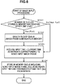
- FIG. 6 is a flowchart illustrating a data input processing sequence from the decoder 102 to the memory 121.
- the flow illustrated in FIG. 6 is executed, for example, under control of the controller 105 and of the output controller 103 according to a program stored in a storage unit.
- FIG. 6 is a process that is repeatedly executed upon an input of a new data from the decoder 102.
- step S101 determination is made whether the number of queues stored in the memory has reached the upper limit (Full).
- the memory 121 described with reference to FIG. 5 is configured so as to be capable of storing two queues, and when two queues are stored, it is determined that the number of queues is at the upper limit (Yes). If under one, then it is determined that the number of queues is not at the upper limit (No).
- step S102 When determined to be at the upper limit (Yes), the process proceeds to step S102. On the other hand, when determined not to be at the upper limit (No), the process proceeds to step S103.
- step S102 When determined that the number of queues stored in the memory 121 is at the upper limit, in step S102, the oldest queue in the memory is deleted. In the case of the memory 121 illustrated in FIG. 5 that stores only two queues, the preceding queue is deleted.
- the queue includes, other than the image frame, metadata, such as the input time and the transmission frame rate (fps); all of the above pieces of data are deleted.
- step S103 After completion of deleting the queue in step S102, or when it is determined that the number of queues stored in the memory is not at the upper limit in step S101, processing of step S103 is executed.
- step S103 in order to set an input time serving as metadata associated with a new image frame that has been input, the current time is acquired.
- the current time information is, for example, acquired from the system clock included in the client 20.
- step S104 data including the new image frame and metadata associated with the new image frame, the metadata including the input time and the transmission frame rate (fps), are stored in the memory as a single queue.
- FIG. 7 is a diagram illustrating a sequence associated with the transition of time from an output of data from the decoder 102 until display processing of the image frame on the display unit 104.
- Time base (t) is illustrated in (C) of FIG. 3 , and (A), (B), and (C) illustrates the processing performed in accordance with the time base (t).
- Each of the F1, F2, F3, F4... indicated in (A), (B), and (C) represents a single image frame.
- F1 is an image frame F1
- F2 is an image frame F2.
- Time t1, time t2, time t3... depicted by solid line arrows 201 on the time base (t) illustrated in (C) of FIG. 7 are each an output timing of the vertical synchronizing signal (Vsync) of the display unit 104 and each indicate a timing in which the relevant output image frame can be switched.
- the vertical synchronizing signal (Vsync) is 60 Hz
- the interval between each sloid line arrow is 1/60 (sec).
- t1m, t2m, t3m... depicted by broken line arrows 202 in (C) of FIG. 7 indicate memory access timings on acquiring images from the memory 121 in order to update the output image of the display unit 104 at the output timings t1, t2, t3... of the vertical synchronizing signals (Vsync) depicted by the solid line arrows 201.
- Vsync vertical synchronizing signals
- the image frame F1 is acquired by accessing the memory 121 at the memory access timing of time t2m.
- the above memory access timing corresponds to a display image update processing start timing.
- the memory illustrated in (B) of FIG. 7 corresponds to the processing of the memory 121 illustrated in FIG. 4 .
- the memory 121 has a configuration that allows two image frames to be stored.
- (b1) on the lower side of (B) is a preceding input image (a preceding queue) and (b2) on the upper side is a succeeding input image (a succeeding queue).
- the broken line arrow 203 extending in the horizontal direction illustrated in (B) of FIG. 7 indicates a buffering time.
- the buffering time is time required to store a single queue in the memory 121. In other words, it is the time from after storing the queue configuration data in the memory 121 has been started at the above-described input time until all of the pieces of queue configuration data are stored completely in the memory 121 such that, subsequently, the queue can be fetched in a stable manner.
- the buffering time is stored in advance in a nonvolatile memory as data unique to the device (the client).
- the buffering time may be time information that can be set by the user.
- the processing of the decoder 102 of storing the output image in the memory 121 is executed according to the flow illustrated in FIG. 6 .
- step S101 is No such that processing from step S103 to S104 is executed.
- a queue including the image frame F1, the time of input of the image frame F1, and the transmission frame rate (fps) is stored in the memory 121.
- step S101 is No such that processing from step S103 to S104 is executed.
- the image frames F2 and F3 are stored in the memory 121.
- the determination in step S101 is Yes.
- step S102 deletion of the oldest queue is executed.
- the oldest queue stored in the memory 121 is the image frame F2, and the image frame F2 and the metadata thereof are deleted.
- succeeding queue F3 is changed to the preceding queue and frame F4 is stored as the succeeding queue.
- a display control sequence of an image frame stored in the memory 121 will be described next.
- the output controller 103 of the information processor (the client 20) of the present disclosure performs different processing depending on the two following states when acquiring an image stored in the memory 121 and outputting the image to the display unit 104.
- (State 1) display update stopped state (uninitialized) is a state in which the image for display update cannot be acquired from the memory 121
- (State 2) display update executing state (initialized) is a state in which the image for display update can be acquired from the memory 121.
- FIG. 8 is a flowchart illustrating a processing sequence of selectively acquiring a queue stored in the memory 121, in other words, a queue that includes an image frame, and an input time and a transmission frame rate (fps) serving as metadata, and displaying the queue on the display unit 104.
- a queue that includes an image frame
- fps transmission frame rate
- the flow illustrated in FIG. 8 is executed, for example, under control of the controller 105 and of the output controller 103 according to a program stored in a storage unit.
- FIG. 8 is a process that is repeatedly executed in accordance with the period of the vertical synchronizing signal (Vsync) of the display unit 104.
- step S201 the display control unit 122 of the output controller 103 waits until a memory access timing (tnm) before the next Vsync.
- the memory access timing (tnm) is a memory access timing corresponding to t1m, t2m... described earlier with reference to FIG. 7 .
- step S202 the display control unit 122 determines whether the present state is the display update executing state (initialized).
- the output controller 103 of the information processor (the client 20) of the present disclosure performs different processing depending on the two following states when acquiring an image stored in the memory 121 and outputting the image to the display unit 104.
- (State 1) display update stopped state (uninitialized) is a state in which the image for display update cannot be acquired from the memory 121
- (State 2) display update executing state (initialized) is a state in which the image for display update can be acquired from the memory 121.
- step S251 If the present state is the display update executing state (initialized), the process proceeds to step S251. The processing in the above case will be described later with reference to FIG. 11 and after.
- step S203 the processing in this case will be described.
- step S203 an update image candidate (Candidate) is set to "none (NULL)".
- the update image candidate (Candidate) is a candidate for the image that is to be displayed next on the display unit 104.
- the display control unit 122 determines whether there is any unprocessed queue that is subject to processing in the memory 121.
- step S205 the display control unit 122 sets the image (tmp) subject to processing as a front queue (Quee.front).
- condition waiting time > buffering time is satisfied by the image (tmp) subject to processing.
- the waiting time is the elapsed time after the queue has been set in the memory 121.
- the above can be calculated as the elapsed time from the input time that is metadata of the image frame set in the queue.
- the buffering time is time required to store a single queue in the memory 121. In other words, it is the time from after storing the queue configuration data in the memory 121 has been started at the above-described input time until all of the pieces of queue configuration data are stored completely in the memory 121 such that, subsequently, the queue can be fetched in a stable manner.
- the buffering time is stored in advance in a nonvolatile memory as data unique to the device (the client).
- the buffering time may be time set by the user.
- step S206 determination is made whether waiting time > buffering time is satisfied by the image (tmp) subject to processing.
- step S206 determines whether the determination condition in step S206, that is waiting time > buffering time is satisfied (Yes). If the determination condition in step S206, that is waiting time > buffering time is satisfied (Yes), the process proceeds to step S207. When not satisfied (No), the process proceeds to step S209.
- step S207 the image (tmp) subject to processing is set as the update image candidate (Candidate).
- the above update image candidate (Candidate) is acquired from the memory.
- step S208 the front queue that has already been acquired as the update image candidate (Candidate) is deleted.
- the succeeding queue is set as the front queue.
- step S204 the process returns to step S204 and repeats the processing from step S204 and after.
- processing subjects are sequentially set and the processing of steps S204 to S208 is executed.
- step S206 when the determination processing of step S206, in other words, when there is a processing subject queue that does not satisfy waiting time > buffering time is detected, the process proceeds to step S209.
- step S209 when there is not a single queue in the memory 121 that satisfy waiting time > buffering time, the update image candidate (Candidate) is not set.
- the newest input image with respect to the memory 121 in other words, a single queue that is the newest is selected and the image of the newest queue is set as the update candidate image (Candidate).
- Step S209 is executed when it is determined in step S204 that there is no unprocessed queue in the memory or that, in step S206, a queue that does not satisfy waiting time > buffering time is detected.
- step S209 determination is made whether the update image candidate (Candidate) is "none (NULL)".
- steps S204 to S208 when there are one or more queues that satisfy waiting time > buffering time, among the one or more queues, the newest input image with respect to the memory 121, in other words, a single queue that is the newest is selected and the image of the newest queue is set as the update candidate image (Candidate).
- the update image candidate (Candidate) is "none (NULL)" and the determination in step S209 is (No), and the process is ended.
- steps S204 to S206 when there are one or more queues that satisfy waiting time > buffering time, among the one or more queues, the newest input image with respect to the memory 121, in other words, a single queue that is the newest is selected and the image of the newest queue is set as the update candidate image (Candidate).
- step S210 the display control unit 122 outputs the update image candidate (Candidate) to the display unit 104 and executes the image update.
- the controller 105 sets the state to display update executing state (initialized).
- the vertical synchronizing signal (Vsync) is set to zero.
- FIG. 9 is a diagram illustrating a sequence associated with the transition of time from an output of data from the decoder 102 until display processing of the image frame on the display unit 104.
- Time base (t) is illustrated in (C) of FIG. 9 , and (A), (B), and (C) illustrates the processing performed in accordance with the time base (t).
- Each of the F1, F2, F3, F4... indicated in (A), (B), and (C) represents a single image frame.
- F1 is an image frame F1
- F2 is an image frame F2.
- Time t1, time t2, time t3... depicted by solid line arrows on the time base (t) illustrated in (C) of FIG. 9 are each an output timing of the vertical synchronizing signal (Vsync) of the display unit 104 and each indicate a timing in which the relevant output image frame can be switched.
- the vertical synchronizing signal (Vsync) is 60 Hz
- the interval between each sloid line arrow is 1/60 (sec).
- time t1m, time t2m, time t3m... indicated by broken line arrows represents memory access timings to acquire images from the memory 121.
- the memory 121 illustrated in (B) of FIG. 9 is the memory 121 illustrated in FIG. 4 and has a configuration that allows two image frames to be stored.
- (b1) on the lower side of (B) is a preceding input image (a preceding queue) and (b2) on the upper side is a succeeding input image (a succeeding queue).
- the image frame F1 displayed on the display unit 104 during the change in state is the image frame that is selected according to the flow illustrated in FIG. 8 .
- the image frame F1 is the update image candidate (Candidate) that is applied to the update processing of the display image in step S210 of the flow illustrated in FIG. 8 .
- the determination processing of the update image candidate (Candidate) is executed by the processing of steps S204 to S208 in the flow illustrated in FIG.8 .
- steps S204 to S208 is repeatedly executed while the front queue to the succeeding queue in the memory are sequentially set as the processing subject (tmp).
- steps S204 to S208 when there are one or more queues that satisfy waiting time > buffering time, among the one or more queues, the newest input image with respect to the memory 121, in other words, a single queue that is the newest is selected and the image of the newest queue is set as the update candidate image (Candidate).
- step S201 and after in FIG. 8 is executed at time t2m.
- the image frame F1 is stored as the preceding queue and the image frame F2 is stored as the succeeding queue in the memory 121.
- the two queues in other words, the image frames F1 and F2, are executed.
- step S206 the determination processing of step S206 is executed on the image frame F1 that is the preceding queue.
- the display control unit 122 acquires the input time that is metadata associated with the image frame F1 and determines whether the criterion waiting time > buffering time is satisfied.
- step S206 Since the above image frame F1 satisfies the criterion described above, the determination in step S206 is Yes and the process proceeds to step S207.
- step S207 the image frame F1 is set as the update image candidate (Candidate).
- step S206 is executed on the image frame F2 that is the succeeding queue.
- the display control unit 122 acquires the input time that is metadata associated with the image frame F2 and determines whether the criterion waiting time > buffering time is satisfied.
- step S206 determines whether the criterion described above is satisfies the criterion described above, that is, the determination in step S206 is No, and the process proceeds to step S209.
- the display control unit 122 outputs the image frame F1 that is set as the update image candidate (Candidate) at this point to the display unit 104, and executes the image update.
- step S210 The above processing is the processing of step S210.
- step S201 and after in FIG. 8 is executed at time t2m.
- the image frame F1 is stored as the preceding queue and the image frame F2 is stored as the succeeding queue in the memory 121.
- the two queues in other words, the image frames F1 and F2, are executed.
- step S206 the determination processing of step S206 is executed on the image frame F1 that is the preceding queue.
- the display control unit 122 acquires the input time that is metadata associated with the image frame F1 and determines whether the criterion waiting time > buffering time is satisfied.
- step S206 Since the above image frame F1 satisfies the criterion described above, the determination in step S206 is Yes and the process proceeds to step S207.
- step S207 the image frame F1 is set as the update image candidate (Candidate).
- step S206 is executed on the image frame F2 that is the succeeding queue.
- the display control unit 122 acquires the input time that is metadata associated with the image frame F2 and determines whether the criterion waiting time > buffering time is satisfied.
- step S206 determines whether the process is satisfies the criterion described above, that is, the determination in step S206 is Yes, and the process proceeds to step S207.
- step S207 the image frame F2 is set as the update image candidate (Candidate).
- step S208 the front queue is deleted.
- the image frame F1 is deleted.
- step S204 the process proceeds to step S204.
- step S204 determination is made whether there is an unprocessed queue in the memory. Since processing of two queues has already been completed, it is determined that there is no unprocessed queue and the process proceeds to step S209.
- the display control unit 122 outputs the image frame F2 that is set as the update image candidate (Candidate) at this point to the display unit 104, and executes the image update.
- step S210 The above processing is the processing of step S210.
- the example illustrated in FIG. 10 is an example of processing in a case in which two queues, that is, both the image frame F1 and the image frame F2, stored in the memory 121, at the point of memory access timing t2m, satisfy the criterion waiting time > buffering time.
- the update processing is performed by setting the image corresponding to the newest input queue as the update candidate image (Candidate).
- FIG. 11 is a flowchart illustrating a processing sequence of selectively acquiring a queue stored in the memory 121, in other words, a queue that includes an image frame, and an input time and a transmission frame rate (fps) serving as metadata, and displaying the queue on the display unit 104.
- a queue that includes an image frame
- fps transmission frame rate
- the flow illustrated in FIG. 11 is executed, for example, under control of the controller 105 and of the output controller 103 according to a program stored in a storage unit.
- the flow illustrated in FIG. 11 is a process that is repeatedly executed in accordance with the period of the vertical synchronizing signal (Vsync) of the display unit 104.
- step S201 to S202 is processing similar to the processing of step S201 to S202 in the flow of FIG. 8 described earlier.
- step S201 the display control unit 122 of the output controller 103 waits until a memory access timing (tnm) before the next Vsync.
- the memory access timing (tnm) is a memory access timing corresponding to t1m, t2m... described earlier with reference to FIG. 7 .
- step S202 the display control unit 122 determines whether the present state is the display update executing state (initialized).
- the output controller 103 of the information processor (the client 20) of the present disclosure performs different processing depending on the two following states when acquiring an image stored in the memory 121 and outputting the image to the display unit 104.
- (State 1) display update stopped state (uninitialized) is a state in which the image for display update cannot be acquired from the memory 121
- (State 2) display update executing state (initialized) is a state in which the image for display update can be acquired from the memory 121.
- step S203 When the present state is not the display update executing state (initialized) but is the display update stopped state (uninitialized), the process proceeds to step S203.
- the processing from step S203 and after is processing that is executed in accordance with the flow illustrated in FIG. 8 described earlier.
- step S251 the processing in the above case will be described below.
- step S251 the vertical synchronizing signal (Vsync) that specifies the image update timing of the display 104 is counted.
- the display control unit 122 determines whether there is any unprocessed queue that is subject to processing in the memory 121.
- step S253 the display control unit 122 sets the image (tmp) subject to processing as a front queue (Quee.front).
- the display control unit 122 acquires a transmission image frame rate (fps) set as metadata associated with an image frame Fx of a front queue that is an image (tmp) subject to processing.
- the transmission frame rate information is information that is received by the client 20 as notification information from the server 30.
- the display control unit 122 retains the frame rate information (fps) associated with the recent display image in the memory, and determines whether the transmission frame rate is to be changed or not by making a comparison with the recent transmission frame rate (fps).
- the server 30 appropriately changes the transmission frame rate in accordance with the congestion situation and the congested state of the network. For example, two rates of 60 fps and 30 fps are used while appropriately switching the two rates.
- step S254 when the change in the server transmission frame rate (fps) is detected, the process proceeds to step S255. On the other hand, when the change in the server transmission frame rate (fps) is not detected, the process proceeds to step S256.
- step S254 when the change in the server transmission frame rate (fps) is detected, the process proceeds to step S255, and, the count of the vertical synchronizing signal of the display unit 1104 is set to zero and the process proceeds to step S256.
- Step S256 is processing executed in either of the following cases.
- Step S256 is executed when in step S252, it is determined that there is no unprocessed queue in the memory 121, when in step S254, the change in the server transmission frame rate (fps) is detected and the process proceeding to step S255 sets the vertical synchronizing signal to zero, when in step S254, the change in the server transmission frame rate (fps) is not detected.
- step S256 determination is made whether the update processing start timing of the display image has come.
- the image update processing start timing is set different according to the transmission frame rate (fps), for example.
- the update is executed each 1/60 (sec), and when the image transmission frame rate from the server 30 is 30 fps, the update is executed each 1/30 (sec).
- step S256 when it is determined that the update processing start timing of the display image has come, the process proceeds to step S257.
- step S256 when it is determined that the update processing start timing of the display image has not come, the process is ended.
- step S256 when it is determined that the update processing start timing of the display image has come, the process proceeds to step S257 and determination is made whether there is an unprocessed queue in the memory 121.
- step S256 it is determined that the update processing start timing of the display image has come, and when, in step S257, it is determined that there is no unprocessed queue in the memory 121, image update on the display unit 104 cannot be performed.
- step S311 the change in state is performed in step S311.
- State 1 display update stopped state (uninitialized) and the process is ended.
- step S256 it is determined that the update processing start timing of the display image has come, and when, in step S257, it is determined that there is no unprocessed queue in the memory 121, the process proceeds to step S321.
- step S321 the display control unit 122 sets the front queue (Queue.front) of the memory 121 to image (tmp) subject to processing and acquires the front queue from the memory 121.
- step S322 the front queue that has already been acquired as the image (tmp) subject to processing is deleted.
- the succeeding queue is set as the front queue.
- step S323 the display control unit 122 outputs, to the display unit 104, the image (tmp) subject to processing that is the front queue that has already been acquired from the memory 121 and executes the image update.
- the display control unit 122 executes the processing of switching the state of the device from the display update executing state (initialized) to the display update stopped state (uninitialized) or from the display update stopped state (uninitialized) to the display update executing state (initialized).
- the waiting time which is the elapsed time from time of input to the memory
- the buffering time which is specified as the required time to store data in the memory
- the image frame that can be acquired from the memory is selected as the output image to the display unit.
- FIGS. 12 and 13 illustrate examples of processing in which the determination processing in step S256 is Yes, that is, in a case in which determination is made that the display image update processing start timing has come in state 2, that is, in the display update executing state (initialized) that has been described with reference to FIG. 11 .
- FIG. 12 is processing in which the determination processing in step S257 is No, that is, is processing in a case in which an unprocessed queue is left in the memory, and is an example of a sequence when the processing of steps S321 to S323 is executed.
- FIG. 13 is processing in which the determination processing in step S257 is Yes, that is, is processing in a case in which no unprocessed queue is left in the memory, and is an example of a sequence when the processing of steps S311 is executed.
- step S321 to S323 a sequence in a case in which an unprocessed queue is left in the memory and in a case in which the processing of step S321 to S323 is executed will be described first.
- FIG. 12 is a diagram illustrating a sequence associated with the transition of time from an output of data from the decoder 102 until display processing of the image frame on the display unit 104.
- Time base (t) is illustrated in (C) of FIG. 12 , and (A), (B), and (C) illustrates the processing performed in accordance with the time base (t).
- Each of the F1, F2, F3, F4... indicated in (A), (B), and (C) represents a single image frame.
- F1 is an image frame F1
- F2 is an image frame F2.
- Time t1, time t2, time t3... depicted by solid line arrows on the time base (t) illustrated in (C) of FIG. 12 are each an output timing of the vertical synchronizing signal (Vsync) of the display unit 104 and each indicate a timing in which the relevant output image frame can be switched.
- the vertical synchronizing signal (Vsync) is 60 Hz
- the interval between each sloid line arrow is 1/60 (sec).
- time t1m, time t2m, time t3m... indicated by broken line arrows represents memory access timings to acquire images from the memory 121.
- the memory 121 illustrated in (B) of FIG. 12 is the memory 121 illustrated in FIG. 4 and has a configuration that allows two image frames to be stored.
- (b1) on the lower side of (B) is a preceding input image (a preceding queue) and (b2) on the upper side is a succeeding input image (a succeeding queue).
- step S321 to S323 executed as the processing of Step S256 of the flow illustrated in FIG. 11 in which determination processing is Yes, that is, determination is made that the display image update processing start timing has come and, further, the processing of step S257 in which the determination processing is No, that is, processing in which an unprocessed queue is left in the memory will be described.
- Time t3m indicated in FIG. 12 is the timing in which the determination processing in step S256 of the flow illustrated in FIG. 11 is Yes, in other words, is one of the timings on which determination is made that the display image update processing start timing has come.
- step S256 of the flow illustrated in FIG. 11 determines whether the display image update processing start timing has come.
- step S257 determination is made whether there is any unprocessed queue in the memory 121.
- step S257 determination processing of step S257 is No, in other words, determination is made that there in an unprocessed queue in the memory 121, and the process proceeds to step S321.
- step S321 the preceding queue, which includes, as its component, the image frame F3 that is stored in the memory 121, is set as the image (tmp) subject to processing and is acquired from the memory 121 by the display control unit 122.
- step S322 the preceding queue, which includes, as its component, the image frame F3 that has already been acquired as the image (tmp) subject to processing, is deleted.
- F4 that is the succeeding queue is set as the front queue.
- step S256 Yes
- step S257 No
- queues are sequentially fetched from the preceding queue stored in the memory 121 to perform display processing.
- step S311 that is executed as processing in a case in which the determination processing in step S257 is Yes, in other words, in a case in which there is no unprocessed queue left in the memory will be described next.
- time t4m indicated in FIG. 13 is the timing in which the determination processing in step S256 of the flow illustrated in FIG. 11 is Yes, in other words, is one of the timings on which determination is made that the display image update processing start timing has come.
- step S256 of the flow illustrated in FIG. 11 determines whether the display image update processing start timing has come.
- step S257 determination is made whether there is any unprocessed queue in the memory 121.
- step S257 determination processing of step S257 is Yes, in other words, determination is made that there is no unprocessed queue in the memory 121, and the process proceeds to step S311.
- State 1 display update stopped state (uninitialized) and the process is ended.
- the update of the display image on the display unit 104 is not executed.
- the display image of the display unit 104 is set as F4, which is the display image between t3 and t4, without change from time t4 and after.
- step S257 Yes
- step S311 the processing of step S311 is executed.
- the update of the display image is not executed and the state change processing to the display update stopped state (uninitialized) is performed.
- the server 30 appropriately changes the transmission frame rate in accordance with the congestion situation and the congested state of the network. For example, two rates of 60 fps and 30 fps are used while appropriately switching the two rates.
- the transmission frame rate information of the server 30 is sequentially notified to the client 20. For example, in step S254 in the flow illustrated in FIG. 11 , when change in the server transmission frame rate (fps) is detected, in step S255, the client 20 performs processing of resetting the vertical synchronizing signal (Vsync) of the display unit 104 and changing the display update timing.
- Vsync vertical synchronizing signal
- FIG. 14 illustrates the processing sequence of the client 20 when the frame rate of the image transmitted by the server 30 is 60 fps.
- FIG. 14 Similar to FIG. 5 and the like described earlier, each of the following data is illustrated in FIG. 14 .
- the decoder output illustrated in (A) of FIG. 14 is substantially the same in intervals with the 60 fps that is the frame rate of the image transmitted by the server 30.
- a single image frame Fn is output each 1/60 (sec) and is stored in the memory.
- the controller 105 illustrated in FIG. 4 notifies the above to the display control unit 122 of the output controller 103.
- the display control unit 122 performs update processing of the display image according to the current image transmission frame rate (fps).
- FIG. 15 illustrates the processing sequence of the client 20 when the frame rate of the image transmitted by the server 30 is 30 fps.
- FIG. 15 Similar to FIG. 14 and the like described earlier, each of the following data is illustrated in FIG. 15 .
- the decoder output illustrated in (A) of FIG. 15 is substantially the same in intervals with the 30 fps that is the frame rate of the image transmitted by the server 30.
- a single image frame Fn is output each 1/30 (sec) and is stored in the memory.
- the image update is performed each 1/30 (sec) by counting the vertical synchronizing signal of 60 Hz.
- the server 30 appropriately changes the transmission frame rate in accordance with, for example, the congestion situation and the congested state of the network.
- the frame rate is lowered. For example, processing of lowering the frame rate of 60 fps to 30 fps is performed.
- the controller 105 of the client 20 illustrated in FIG. 4 outputs a metadata setting command to the decoder 102 on the basis of the notification information on the transmission rate change.
- the transmission frame rate (fps) is set and is stored in the memory 121.
- the display control unit 122 On the basis of the metadata set in the queue that has been fetched from the memory 121, the display control unit 122 detects that the transmission frame rate has been changed and, on the basis of the detection information, changes the display update rate of the image of the display unit 104.
- the display control unit determines whether there has been a change in the frame rate by retaining the metadata of the data acquired one data before from the memory and performing a comparison with the transmission frame rate (fps) information of the above preceding metadata.
- FIG. 16 An example of display control processing ( FIG. 16 ) when there is an unprocessed image (undisplayed image), in which the buffering time has passed and that includes the frame rate change information, at the first display image update processing start timing (tnm) after the timing of the notification of the transmission rate reduction received by the client.
- FIGS. 16 to 18 each illustrate each of the following data.
- Specific example 1 An example of display control processing when there is an unprocessed image (undisplayed image), that includes the frame rate change information and in which the buffering time has passed, at the first display image update processing start timing (tnm) after the timing of the notification of the transmission rate reduction received by the client.
- FIG. 16 it is assumed that the client 20 receives the notification that the image frame rate (fps) transmitted by the server has been changed from 60 fps to30 fps at time tc denoted on the time base (t) in (C) of FIG. 16 .
- the display control unit 122 of the client 20 acquires the image frame F4, that includes the frame rate change information and in which the buffering time has passed, at the next display image update processing start timing (t4m).
- the reduction of the frame rate (60 fps ⁇ 30 fps) is verified, and from this point, the display update timing is changed to 30 fps corresponding to the transmission frame rate.
- the image update timing is changed to 30 fps from 60 fps until then. Specifically, update of the image is performed at every second signal timing of the vertical synchronizing signal (Vsync) of 60 Hz, in other words, at every 1/30 (sec).
- Vsync vertical synchronizing signal
- the client 20 receives the notification that the image frame rate (fps) transmitted by the server has been changed from 60 fps to30 fps at time tc denoted on the time base (t) in (C) of FIG. 17 .
- the buffering time of the image frame F4 which includes the frame rate change information has not passed. Accordingly, when processing that takes buffer time into consideration is executed, the image F4 cannot be acquired from the memory.
- the display control unit 122 of the client 20 acquires the newest input image frame F4 that includes the frame rate change information from the memory 121 at the next display image update processing start timing (t4m) and performs update of the display.
- the image frame F4 is continuously displayed in the next 60 fps display image update processing start timing (t5m).
- the next display image update processing start timing (t6m) the newest input image frame F5 is acquired and the update of the display is performed.
- processing of changing to 30 fps, which corresponds to the transmission frame rate is performed at the display timing of the image frame F4 that has been acquired in success from the memory 121 and in which the buffering time has not passed.
- the client 20 receives the notification that the image frame rate (fps) transmitted by the server has been changed from 60 fps to30 fps at time tc denoted on the time base (t) in (C) of FIG. 18 .
- the reception time tc of the notification of the reduction in the frame rate is a time zone of the display update stopped state (uninitialized) in which no unprocessed queue exists in the memory.
- the newest input image frame F4 in which the buffering time has passed and that includes the frame rate change information, is acquired and update of the display is performed. From the image frame F4, the display update timing is changed to 30 fps that corresponds to the transmission frame rate.
- the above state change processing corresponds to the processing of step S211 in the flow illustrated in FIG. 8 .
- the server 30 appropriately changes the transmission frame rate in accordance with, for example, the congestion situation and the congested state of the network.
- the frame rate is increased. For example, processing of increasing the frame rate of 30 fps to 60 fps is performed.
- the controller 105 of the client 20 illustrated in FIG. 4 outputs a metadata setting command to the decoder 102 on the basis of the notification information on the transmission rate change.
- the transmission frame rate (fps) is set and is stored in the memory 121.
- the display control unit 122 On the basis of the metadata set in the queue that has been fetched from the memory 121, the display control unit 122 detects that the transmission frame rate has been changed and, on the basis of the detection information, changes the display update rate of the image of the display unit 104.
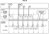
- FIGS. 19 to 21 each illustrate each of the following data.
- FIG. 19 it is assumed that the client 20 receives the notification that the image frame rate (fps) transmitted by the server has been changed from 30 fps to 60 fps at time tc denoted on the time base (t) in (C) of FIG. 19 .
- the display image update processing start timing (t3m) of the image including the first frame rate change information after the time tc at which the notification of the frame rate increase has been received matches the display image update start timing when at a low frame rate (30 fps).
- the display control unit 122 of the client 20 acquires the image frame F2, in which the buffering time has passed at the display image update processing start timing (t3m) and that includes the frame rate change information, and on the basis of the metadata of the image frame F2, verifies that the transmission frame rate has been changed from 30 fps to 60 fps. On the basis of the verification, the display control unit 122 changes, from the image frame F2, the display update timing to 60 fps that corresponds to the transmission frame rate.
- the image update timing is changed to 60 fps from 30 fps until then. Specifically, update of the image is performed at every signal timing of the vertical synchronizing signal (Vsync) of 60 Hz, in other words, at every 1/60 (sec).
- Vsync vertical synchronizing signal
- the client 20 receives the notification that the image frame rate (fps) transmitted by the server has been changed from 30 fps to 60 fps at time tc denoted on the time base (t) in (C) of FIG. 20 .
- the first display image update processing start timing (t2m) after the time tc at which the notification of the frame rate increase has been received does not match the display image update start timing when at a low frame rate (30 fps).
- the image F2 in which the buffering time has already passed and that includes the frame rate change information is stored in the memory 121.
- the display control unit 122 acquires the image frame F2, in which the buffering time has passed at the display image update processing start timing (t2m) and that includes the frame rate change information, and on the basis of the metadata of the image frame F2, verifies that the transmission frame rate has been changed from 30 fps to 60 fps.
- the display control unit 122 changes, from the image frame F2 that has been acquired at the display image update processing start timing (t2m), the display update timing to 60 fps that corresponds to the transmission frame rate.
- the image update timing is changed to 60 fps from 30 fps until then. Specifically, update of the image is performed at every signal timing of the vertical synchronizing signal (Vsync) of 60 Hz, in other words, at every 1/60 (sec).
- Vsync vertical synchronizing signal
- FIG. 21 it is assumed that the client 20 receives the notification that the image frame rate (fps) transmitted by the server has been changed from 30 fps to 60 fps at time tc denoted on the time base (t) in (C) of FIG. 21 .
- the reception time tc of the notification of the increase in frame rate is a time zone of the display update stopped state (uninitialized) in which no unprocessed queue exists in the memory.
- the newest input image frame F2 in which the buffering time has passed and that includes the frame rate change information, is acquired and update of the display is performed. From the image frame F2, the display update timing is changed to 60 fps that corresponds to the transmission frame rate.
- the above state change processing corresponds to the processing of step S211 in the flow illustrated in FIG. 8 .
- FIG. 22 illustrates an exemplary hardware configuration of the information processor serving as the client.
- the central processing unit (CPU) 401 functions as a data processing unit that executes various processing in accordance to a program stored in a read-only memory (ROM) 402 or a storage unit 408. For example, the process according to the sequence described in the embodiment described above is executed.
- a program executed by the CPU 401 and data are stored in a random-access memory (RAM) 403.
- the CPU 401, the ROM 402, and the RAM 403 are interconnected with a bus 404.
- the CPU 401 is connected to an input/output interface 405 through the bus 404, and an input unit 406 including various switches, a key board, a mouse, a microphone, and the like and an output unit 407 including a display, a loudspeaker and the like are connected to the input/output interface 405.
- the CPU 401 executes various processing in response to commands input from the input unit 406, and outputs the processing results to, for example, the output unit 407.
- the storage unit 408 that is connected to the input/output interface 405 is, for example, configured of a hard disk or the like and stores a program that is executed by the CPU 401 and various data.
- a communication unit 409 functions as a transmission/reception unit of data communication through networks such as the Internet and a local area network and, further, functions as a transmission/reception unit of broadcast waves.
- a drive 410 connected to the input/output interface 405 drives a removable media 411 such as a magnetic disk, an optical disc, a magneto-optical disk, or a semiconductor memory such as a memory card and executes recording or a read-out of data.
- a removable media 411 such as a magnetic disk, an optical disc, a magneto-optical disk, or a semiconductor memory such as a memory card and executes recording or a read-out of data.
- the configuration may be such that a codec serving as a dedicated hardware for executing coding processing or decoding processing is provided.
- the processing sequence that is explained in the specification can be implemented by hardware, by software and by a configuration that combines hardware and software.
- the processing is implemented by software, it is possible to install in memory within a computer that is incorporated into dedicated hardware a program in which the processing sequence is encoded and to execute the program.
- a program in a general-purpose computer that is capable of performing various types of processing and to execute the program.
- the program can be installed in advance in a storage medium.
- the program can also be received through a network, such as a local area network (LAN) or the Internet, and can be installed in a storage medium such as a hard disk or the like that is built into the computer.
- LAN local area network
- the Internet can be installed in a storage medium such as a hard disk or the like that is built into the computer.
- a device and a method are provided that is capable of display control of image data, which is received through a communication unit, with a small delay.
- an image frame, and memory input time and transmission frame rate information that serve as metadata are stored in the memory storing the image frame.
- the display control unit selects the image that is output to the display unit on the basis of the elapsed time from the input time information.
- the waiting time, which is the elapsed time from the input time, and the buffering time are compared with each other in each of the queues, and the image frame corresponding to the newest queue, which is a queue among the queues in which the waiting time exceeds the buffering time, is selected as the output image to the display unit.
- the display rate of the display unit is changed in addition to the change in the transmission frame rate.
- a device and a method are provided that is capable of display control of image data, which is received through a communication unit, with a small delay.
Landscapes
- Engineering & Computer Science (AREA)
- Physics & Mathematics (AREA)
- General Physics & Mathematics (AREA)
- Theoretical Computer Science (AREA)
- Computer Hardware Design (AREA)
- Multimedia (AREA)
- Two-Way Televisions, Distribution Of Moving Picture Or The Like (AREA)
- Controls And Circuits For Display Device (AREA)
Description
- The present disclosure relates to an information processor, an information processing method, and a program. In further detail, the present disclosure relates to an information processor, an information processing method, and a program that enables display of an image data sent from the server to be executed with a small delay.
- Recently, a so-called cloud computing system that transmits a data processing request from a client such as, for example a portable terminal, to a server, executes data processing on the server side and returns a processing result to the client, and obtains the data processing result on the client side is starting to become widely used.
- An example of the utilization of the cloud system includes execution of games on a game terminal. It is a system in which a game terminal (a client) that a user operates communicates with a server, and by the use of a high-function data processing function on the server side, image data such as a developing display of the game is provided to the client.
- In such a cloud based game system, user operation information is transmitted from the client to the server. The server develops the game according to the operation information sent from the client, generates updated image and audio data, and transmits the updated image and audio data to the client. The client reproduces the updated image and audio sent from the server. By performing such a process, even a client that is not equipped with a high function processor and the like is capable of obtaining the data processing results using the server-side high-function data processing function.
- However, when the transfer data between the server and the client is data with a large data size such as image data, delays and jitters (fluctuation) occur according to the state of the network. Typically, image and audio data needs to be transmitted as coded data, the client needs to store the received coded data in a buffer, and the coded data needs to be sequentially decoded and output.
- When a packet delay and a jitter (fluctuation) occur according to the state of the network, delays in reception of the packet, decoding, display, and the sequential process of the above occur on the client side and, as a result, there are cases in which a timely image display cannot be performed in the client.
- Note that as a known technology, for example, Patent Literature 1 (
JP 2005-159787A -
- Patent Literature1:
-
JP 2005-159787A -
US 2013/166769 A1 discloses a screen frame transmission method including a transmitting end capturing screen frame data and audio data and transmitting the same to a receiving end, and detecting for a user's operation and outputting a mode switching signal; a receiving end buffering the screen frame data transmitted by the transmitting end, and according to the mode switching signal, switching to the operating mode or the video mode, wherein during the video mode, a longer playback period of the screen frame data are buffered, and during the operating mode, a shorter playback period of the screen frame data are buffered. According to the aforementioned method, during the video mode, the video may be played back smoothly and the video and the audio are synchronized; during the operating mode, a low latency delay control experience may be provided. A receiving device and screen frame transmission system realizing the above method are also disclosed. -
WO 2014/038319 A1 discloses an image data output control device. If, after completing the output of image data for the first time, image data for the next screen is not input from a host even after the lapse of a first predetermined time, a period control unit starts to output said image data, which was output the first time, for the second time to a liquid crystal display device. If, after completing the output of said image data for the second time, image data for the next screen is not input from the host even after the lapse of a second predetermined time, the period control unit starts to output said image data to the liquid crystal display device for the third time, and sets the first predetermined time to be longer than the second predetermined time. Thus, the displayed image can be updated appropriately. - In a cloud system described above, when decoding and displaying the image data that the client receives from the server, there is a possibility of a delay occurring, and such a delay is, in a case of a game machine or the like, for example, reflected as degradation in the responsiveness of the user operation and, accordingly, reduces the fun of the game by half.
- The present disclosure is, for example, made in view of the above problem and an object thereof is to provide an information processor, an information processing method, and a program that achieve data output in which delay is reduced.
- According to the present disclosure, there are provided an information processor, an information processing method and a program as defined in the claims.
- Note that the program according to the present disclosure is a program that can be provided in a storage medium or communication medium that is provided in a computer-readable form for an information processing device or a computer system that is capable of executing various types of program code, for example. Providing this sort of program in a computer-readable form makes it possible to implement the processing according to the program in the information processing device or the computer system.
- The object, features, and advantages of the present disclosure will be made clear later by a more detailed explanation that is based on the embodiments of the present disclosure and the appended drawings. Furthermore, the system in this specification is not limited to being a configuration that logically aggregates a plurality of devices, all of which are contained within the same housing.
- According to a configuration of an embodiment of the present disclosure, a device and a method are provided that is capable of display control of image data, which is received through a communication unit, with a small delay.
- Specifically, an image frame, and memory input time and transmission frame rate information that serve as metadata are stored in the memory storing the image frame. The display control unit selects the output image to the display unit on the basis of the elapsed time from the input time information. The waiting time, which is the elapsed time from the input time, and the buffering time are compared with each other in each of the queues, and the image frame associated with the newest queue, which is a queue among the queues in which the waiting time exceeds the buffering time, is selected as the output image to the display unit. Furthermore, when there is a change in the transmission frame rate, the display rate of the display unit is changed in addition to the change in the transmission frame rate.
- With the present configuration, a device and a method are provided that is capable of display control of image data, which is received through a communication unit, with a small delay.
- Note that the effects described in the present description are only exemplifications and the effects are not limited to those described in the present description and, further, there may be additional effects.
-
- [
FIG. 1] FIG. 1 is a diagram for describing an exemplary configuration of a communication system that executes processing of the present disclosure. - [
FIG. 2] FIG. 2 is a diagram for describing a configuration of a typical client. - [
FIG. 3] FIG. 3 is a diagram for explaining a delay in the image display of the client. - [
FIG. 4] FIG. 4 is a diagram for describing an exemplary configuration of a client of the present disclosure. - [
FIG. 5] FIG. 5 is a diagram for describing an example in which the display delay in the client of the present disclosure is reduced. - [
FIG. 6] FIG. 6 is a diagram illustrating a flowchart for describing a sequence of storing image data in the memory. - [
FIG. 7] FIG. 7 is a diagram for describing a specific example of the sequence of storing image data in the memory. - [
FIG. 8] FIG. 8 is a diagram illustrating a flowchart for describing an image display control sequence in a display update stopped state (uninitialized). - [
FIG. 9] FIG. 9 is a diagram for describing a specific example of the image display control sequence in the display update stopped state (uninitialized). - [
FIG. 10] FIG. 10 is a diagram for describing a specific example of the image display control sequence in the display update stopped state (uninitialized). - [
FIG. 11] FIG. 11 is a diagram illustrating a flowchart for describing an image display control sequence in a display update executing state (initialized). - [
FIG. 12] FIG. 12 is a diagram for describing a specific example of the image display control sequence in the display update executing state (initialized). - [
FIG. 13] FIG. 13 is a diagram for describing a specific example of the image display control sequence in the display update executing state (initialized). - [
FIG. 14] FIG. 14 is a diagram for describing a specific example of the image display control sequence in a case in which transmission frame rate = 60 fps. - [
FIG. 15] FIG. 15 is a diagram for describing a specific example of the image display control sequence in a case in which transmission frame rate = 30 fps. - [
FIG. 16] FIG. 16 is a diagram for describing a specific example of the image display control sequence in a case in which the transmission frame rate is changed from 60 fps to 30 fps. - [
FIG. 17] FIG. 17 is a diagram for describing a specific example of the image display control sequence in a case in which the transmission frame rate is changed from 60 fps to 30 fps. - [
FIG. 18] FIG. 18 is a diagram for describing a specific example of the image display control sequence in a case in which the transmission frame rate is changed from 60 fps to 30 fps. - [
FIG. 19] FIG. 19 is a diagram for describing a specific example of the image display control sequence in a case in which the transmission frame rate is changed from 30 fps to 60 fps. - [
FIG. 20] FIG. 20 is a diagram for describing a specific example of the image display control sequence in a case in which the transmission frame rate is changed from 30 fps to 60 fps. - [
FIG. 21] FIG. 21 is a diagram for describing a specific example of the image display control sequence in a case in which the transmission frame rate is changed from 30 fps to 60 fps. - [
FIG. 22] FIG. 22 is a diagram for describing an exemplary hardware configuration of an information processor serving as the client. - Hereinafter, details of an information processor, an information processing method, and a program of the present disclosure will be described with reference to the drawings. Note that the description will be made according to the following items.
- 1. Exemplary Configuration of Communication System
- 2. Delay in Reception, Decoding, and Output Process of Image Data
- 3. Outline of Configuration and Processing of Information Processor of Present Disclosure
- 4. Memory Storing Sequence of Decoded Image Executed by Information Processor (Client) of Present Disclosure
- 5. Detailed Sequence of Image Display Control Processing Executed by Information Processor (Client) of Present Disclosure
- 5-1. Processing in Display Update Stopped State (Uninitialized)
- 5-2. Processing in Display Update Executing State (Initialized)
- 6. Processing in response to Switching of Image Transmission Frame Rate (fps) of Server
- 6-1. Basic Display Control Processing Executed by Client When Transmission Frame Rates (fps) are 60 fps and 30 fps
- 6-2. Display Control Processing Executed by Client When Transmission Frame Rates (fps) are Changed from 60 fps to 30 fps
- 6-3. Display Control Processing Executed by Client When Transmission Frame Rates (fps) are Changed from 30 fps to 60 fps
- 7. Exemplary Configuration of Information Processor Serving as Client
- 8. Conclusion of Configuration of Present Disclosure
- Referring first to
FIG. 1 , an exemplary configuration of a communication system that executes the processing of the present disclosure will be described. - As illustrated in
FIG. 1 , acommunication system 10 includes aclient 20 and aserver 30 that are capable of bidirectional communication. Theclient 20 and theserver 30 perform communication through a network such as the Internet, for example. - The
client 20 is a device for a general user and, specifically, is atelevision 21, aPC 22, a game machine, or aportable terminal 23 such as a smart phone, for example. - The
client 20 transmits user operation information on theclient 20 to theserver 30. Theserver 30 performs data processing in response to the received operation information from theclient 20. For example, when the user is in the midst of playing a game with theclient 20, the game is developed in accordance with the user operation and stream data in which the updated image and audio data are coded is generated and is transmitted to theclient 20. - The
client 20 decodes the stream data sent from theserver 30 and outputs the image and audio, which are results of the decoding, through a display or a loudspeaker. - In the
communication system 10, such as the one illustrated inFIG. 1 , a delay and a jitter (fluctuation) are generated in the communication data between theclient 20 and theserver 30 in accordance with the network state. Typically, image and audio data needs to be transmitted as coded data, theclient 20 needs to store the received coded data in a buffer, and the coded data needs to be sequentially decoded and output. - When a packet delay and a jitter (fluctuation) occur, delays in reception of the packet, decoding, display, and the sequential process of the above occur on the
client 20 side and, as a result, there are cases in which a timely image display cannot be performed in theclient 20. - A specific example of the occurrence of a delay will be described with reference to
FIGS. 2 and3 . -
FIG. 2 is a diagram illustrating an exemplary configuration of atypical client 20. - A
communication unit 51 receives stream data including image coded data and audio coded data transmitted by theserver 30. - The received data is decoded in a
decoder 52. - Note that processing of the image data will be described below.
- The decoded image data is stored in a
memory 71 of anoutput controller 53 in units of an image frame. - The
memory 71 is configured so as to be capable of storing a plurality of image frames as a queue. - Herein, the
memory 71 is configured so as to be capable of storing two image frames (indicated as F1 and F2 in the drawing). - The
display control unit 72 sequentially acquires image frames that have been decoded and that have been stored in thememory 71 and outputs the image frames to thedisplay unit 54. - The
display unit 54 outputs, for example, a 60 Hz vertical synchronizing signal (Vsync) to thedisplay control unit 72, and, at a timing determined on the basis of the synchronizing signal, thedisplay control unit 72 sequentially outputs the image frames to thedisplay unit 54 and executes an image update. - A
controller 55 performs a general control related to processing of each component. - Referring to
FIG. 3 , a delay time from when the image frame from thedecoder 52 is stored in thememory 71 until when the decoded image is displayed on thedisplay unit 54 will be described. -
FIG. 3 is a diagram illustrating a sequence associated with the transition of time from an output of data from thedecoder 52 until display processing of the image frame on thedisplay unit 54. - Each of the following data is illustrated in
FIG. 3 . - (A) An output of the decoder
- (B) Stored data in the memory
- (C) The image displayed on the display unit with the processing of the display control unit
- Time base (t) is illustrated in (C) of
FIG. 3 , and (A), (B), and (C) illustrates the processing performed in accordance with the time base (t). - Each of the F1, F2, F3, F4... indicated in (A), (B), and (C) represents a single image frame.
- F1 is an image frame F1, and F2 is an image frame F2.
- Illustrated in (A) of
FIG. 3 is a sequence in which thedecoder 52 decodes the encoded image data input from thecommunication unit 51 and outputs the decoded data to thememory 71. - The intervals between the Frames F1, F2, F3, and F4 are different due to jitters (fluctuation) and the like of the network communication. A certain variation occurs in the reception intervals of the image frames and, in accordance with the reception intervals, a variation occurs in the intervals of the data output from the
decoder 52. - The
memory 71 in (B) ofFIG. 3 has a configuration that allows two image frames to be stored. InFIG. 3 , (b1) on the lower side of (B) is a preceding input image (a preceding queue) and (b2) on the upper side is a succeeding input image (a succeeding queue). - In the example illustrated in the drawing, at time t0, the frame F1 is stored in the memory as a preceding input queue and, after that, frame F2 is stored as a succeeding queue.
- Note that the length of the frame Fn illustrated in (B) of
FIG. 3 corresponds to the time stored in the memory. - For example, frame F1 is stored in the memory as a preceding queue between time t0 to t1.
- Frame F2 is stored in the memory as a succeeding queue at an intermediate time between time t0 and t1 and is set as the succeeding queue until time t1. After that, it is illustrated that between time t1 to t2, the frame F2 is stored in the memory as a preceding queue.
- In (C) of
FIG. 3 , a sequence related to the processing of thedisplay control unit 72 and the display image of thedisplay unit 54 is illustrated. - The frame F1 stored in the memory is fetched from the
memory 71 by thedisplay control unit 72 and is output to thedisplay unit 54 between time t1 to time t2. - At time t1, when the frame F1 is fetched from the memory, the frame F2 that had been the succeeding queue is changed to the preceding queue.
- Note that, strictly speaking, there is a time lag between when the image frame is fetched from the
memory 71 and when the image frame is output to thedisplay unit 54; however, the above is omitted from the illustration inFIG. 3 . - Subsequently, the frame F3 that is output from the decoder is set as the succeeding queue.
- At time t2, the display image of the
display unit 54 is switched to frame F2. - At time t2, the frame F3 that had been the succeeding queue of the memory becomes the preceding queue and, subsequently, the frame F4 input from the decoder is stored as the succeeding queue.
- In the sequence illustrated in
FIG. 3 from decoding the image until displaying the image, while the output time of the image frame F1 from thedecoder 52 to thememory 71 is t0, the display start time of thedisplay unit 54 is t1, for example. - In other words, a delay from
time 0 to t1 occurs from when the decoding has been completed until the display is started. - In the processing of the present disclosure, a configuration that reduces such a delay is implemented.
-
FIG. 4 is a diagram illustrating an exemplary configuration of theclient 20 serving as an information processor of the present disclosure. The configuration of theclient 20 illustrated inFIG. 4 corresponds to a partial configuration of the client that mainly performs image processing. - A
communication unit 101 receives stream data including image coded data and audio coded data transmitted by theserver 30. - The received data is decoded in a
decoder 102. - The decoded image data decoded in the
decoder 102 is stored in amemory 121 of anoutput controller 103 in units of an image frame. - The
memory 121 is configured so as to be capable of storing a plurality of image frames as a queue. - Herein, similar to the
memory 71 described earlier with reference toFIG. 2 , thememory 121 is configured so as to be capable of storing two image frames (indicated as F1 and F2 in the drawing). - A
display control unit 122 sequentially acquires image frames that have been stored in thememory 121 and outputs the image frames to thedisplay unit 104. - The
display unit 104 outputs, for example, a 60 Hz vertical synchronizing signal (Vsync) to thedisplay control unit 122, and, at a timing determined on the basis of the synchronizing signal, thedisplay control unit 122 sequentially updates the output image frames to thedisplay unit 104. - The
display control unit 122 and thedisplay unit 104 are connected to each other with an HDMI (registered trademark) cable. - The
controller 55 performs a general control related to processing of each component. - The above basic configuration is a configuration similar to that of the conventional device described earlier with reference to
FIG. 2 . - The
client 20 illustrated inFIG. 4 stores, in thememory 121, not only the image frames (Fn) but also the following metadata associated with the image frames in addition to the image frames. - (1) Time input to the memory
- (2) Transmission frame rate (fps) of the image data from the
server 30 - The above metadata is stored after associating the metadata with the image frames.
- The
server 30 appropriately changes the frame rate of the image to be transmitted in accordance with the state of the network. The information on the transmission frame rate is notified to the client from theserver 30. Acontroller 105 fetches the information on the transmission frame rate (fps) from the notified information that has been received through thecommunication unit 101. Thedecoder 102 associates the transmission frame rate with the decoded image that is to be output and stores the resultant decoded image in thememory 121. - Furthermore, the
controller 105 inputs time information from a system clock (not shown) and provides the time information to thedecoder 102. Thedecoder 102 associates, with the decoded image, the time to input the image frame in thememory 121 as metadata = input time described above and stores the decoded image in thememory 121. - As a result, as illustrated in the drawing, in the
memory 121, the following pieces of data - (1) image frame
- (2) input time (time in which the image frame has been input in the memory)
- (3) transmission frame rate (fps)
- The display control unit uses the above data (1) to (3) to execute a display control of the image that is acquired from the
memory 121 and that is output to thedisplay unit 104. - Details of the processing of the above will be described later.
- In the processing of the present disclosure, the time of input of the decoded image to the
memory 121 is recorded as metadata associated with the relevant image frame. - The
display control unit 122, for example, calculates, for each image frame, the elapsed time after being stored in the memory, and on the basis of the calculation result, performs processing of determining the output image. -
FIG. 5 is a diagram illustrating an example of an image output sequence that the information processor (the client 20) of the present disclosure executes. - Similar to
FIG. 3 described earlier,FIG. 5 is a diagram illustrating a sequence associated with the transition of time from an output of data from thedecoder 102 until display processing of the image frame on thedisplay unit 104. - Each of the following data is illustrated in
FIG. 5 . - (A) An output of the decoder
- (B) Stored data in the memory
- (C) The image displayed on the display unit with the processing of the display control unit
- Time base (t) is illustrated in (C) of
FIG. 5 , and (A), (B), and (C) illustrates the processing performed in accordance with the time base (t). - Each of the F1, F2, F3, F4... indicated in (A), (B), and (C) represents a single image frame.
- F1 is an image frame F1, and F2 is an image frame F2.
- The memory in (B) of
FIG. 5 has a configuration that allows two image frames to be stored. InFIG. 5 , (b1) on the lower side of (B) is a preceding input image (a preceding queue) and (b2) on the upper side is a succeeding input image (a succeeding queue). - In the example illustrated in the drawing, at time t0, the frame F1 is stored in the memory as a preceding input queue and, after that, frame F2 is stored as a succeeding queue.
- Note that similar to the description given earlier with reference to
FIG. 3 , the length of the frame Fn illustrated in (B) ofFIG. 5 corresponds to the time stored in the memory. - For example, frame F1 is stored in the memory as a preceding queue between time t0 to t1.
- Frame F2 is stored in the memory as a succeeding queue at an intermediate time between time t0 and t1 and is set as the succeeding queue until time t1. After that, it is illustrated that between time t1 to t2, the frame F2 is stored in the memory as a preceding queue.
- In (C) of
FIG. 5 , a sequence related to the processing of thedisplay control unit 122 and the display image of thedisplay unit 104 is illustrated. - In the example illustrated in
FIG. 5 , at time t1, thedisplay control unit 122 does not select frame F1 but selects frame F2 that are stored in the memory and outputs the frame F2 to thedisplay unit 104. - The processing of selecting the above display image is executed as processing using the metadata associated with the image frame that is to be stored in the memory.
- In the sequence illustrated in
FIG. 5 from decoding the image until the image is displayed, the delay time of the image frame F2, in other words, the delay time that is from the output time of the frame F2 from thedecoder 102 to thememory 121 until the display start time of the frame F2 on thedisplay unit 104, is short compared with the delay time of the frame F1 in the sequence described with reference toFIG. 3 . - As described above, in the configuration of the present disclosure, shortened delay in displaying the image is stored.
- The above can be achieved by selecting the display image by using the metadata associated with the image frame that is to be stored in the memory.
- The above processing will be described in detail below.
- Next, a memory storing sequence of a decoded image executed by the information processor (client) of the present disclosure will be described.
-
FIG. 6 is a flowchart illustrating a data input processing sequence from thedecoder 102 to thememory 121. - The flow illustrated in
FIG. 6 is executed, for example, under control of thecontroller 105 and of theoutput controller 103 according to a program stored in a storage unit. - Note that the flow illustrated in
FIG. 6 is a process that is repeatedly executed upon an input of a new data from thedecoder 102. - Processing in each step will be described below.
- First, in step S101, determination is made whether the number of queues stored in the memory has reached the upper limit (Full).
- For example, the
memory 121 described with reference toFIG. 5 is configured so as to be capable of storing two queues, and when two queues are stored, it is determined that the number of queues is at the upper limit (Yes). If under one, then it is determined that the number of queues is not at the upper limit (No). - When determined to be at the upper limit (Yes), the process proceeds to step S102. On the other hand, when determined not to be at the upper limit (No), the process proceeds to step S103.
- When determined that the number of queues stored in the
memory 121 is at the upper limit, in step S102, the oldest queue in the memory is deleted. In the case of thememory 121 illustrated inFIG. 5 that stores only two queues, the preceding queue is deleted. - Note that the queue includes, other than the image frame, metadata, such as the input time and the transmission frame rate (fps); all of the above pieces of data are deleted.
- After completion of deleting the queue in step S102, or when it is determined that the number of queues stored in the memory is not at the upper limit in step S101, processing of step S103 is executed.
- In step S103, in order to set an input time serving as metadata associated with a new image frame that has been input, the current time is acquired. The current time information is, for example, acquired from the system clock included in the
client 20. - Subsequently, in step S104, data including the new image frame and metadata associated with the new image frame, the metadata including
the input time and
the transmission frame rate (fps),
are stored in the memory as a single queue. - A specific exemplary sequence of processing that stores data in the memory will be described with reference to
FIG. 7 . - Similar to
FIG. 5 described earlier,FIG. 7 is a diagram illustrating a sequence associated with the transition of time from an output of data from thedecoder 102 until display processing of the image frame on thedisplay unit 104. - Each of the following data is illustrated in
FIG. 3 . - (A) An output of the decoder
- (B) Stored data in the memory
- (C) The image displayed on the display unit with the processing of the display control unit
- Time base (t) is illustrated in (C) of
FIG. 3 , and (A), (B), and (C) illustrates the processing performed in accordance with the time base (t). - Each of the F1, F2, F3, F4... indicated in (A), (B), and (C) represents a single image frame.
- F1 is an image frame F1, and F2 is an image frame F2.
- Time t1, time t2, time t3... depicted by
solid line arrows 201 on the time base (t) illustrated in (C) ofFIG. 7 are each an output timing of the vertical synchronizing signal (Vsync) of thedisplay unit 104 and each indicate a timing in which the relevant output image frame can be switched. When the vertical synchronizing signal (Vsync) is 60 Hz, the interval between each sloid line arrow is 1/60 (sec). - Furthermore, t1m, t2m, t3m... depicted by
broken line arrows 202 in (C) ofFIG. 7 indicate memory access timings on acquiring images from thememory 121 in order to update the output image of thedisplay unit 104 at the output timings t1, t2, t3... of the vertical synchronizing signals (Vsync) depicted by thesolid line arrows 201. - In other words, for example, in order to display the image frame F1 on the display unit at time t2, the image frame F1 is acquired by accessing the
memory 121 at the memory access timing of time t2m. - The above memory access timing corresponds to a display image update processing start timing.
- The memory illustrated in (B) of
FIG. 7 corresponds to the processing of thememory 121 illustrated inFIG. 4 . Thememory 121 has a configuration that allows two image frames to be stored. InFIG. 7 , (b1) on the lower side of (B) is a preceding input image (a preceding queue) and (b2) on the upper side is a succeeding input image (a succeeding queue). - The
broken line arrow 203 extending in the horizontal direction illustrated in (B) ofFIG. 7 indicates a buffering time. - The buffering time is time required to store a single queue in the
memory 121. In other words, it is the time from after storing the queue configuration data in thememory 121 has been started at the above-described input time until all of the pieces of queue configuration data are stored completely in thememory 121 such that, subsequently, the queue can be fetched in a stable manner. - The buffering time is stored in advance in a nonvolatile memory as data unique to the device (the client).
Alternatively, the buffering time may be time information that can be set by the user. - The processing of the
decoder 102 of storing the output image in thememory 121 is executed according to the flow illustrated inFIG. 6 . - For example, when the frame F1 is input in the
memory 121 from thedecoder 102, the storage queue of the memory is zero and the determination in step S101 is No such that processing from step S103 to S104 is executed. - As a result, a queue including the image frame F1, the time of input of the image frame F1, and the transmission frame rate (fps) is stored in the
memory 121. - The same applies when inputting frame F2 in the
memory 121 from thedecoder 102. - Furthermore, at the time when the frame F3 is input in the
memory 121 from thedecoder 102, the image frame F1 that is the preceding queue of thememory 121 is acquired by the display control unit. Accordingly, when the frame F3 is input in thememory 121, the determination in step S101 is No such that processing from step S103 to S104 is executed. - However, for example, in the example illustrated in
FIG. 7 , when inputting the frame F4 in thememory 121 from thedecoder 102, the image frames F2 and F3 are stored in thememory 121. In other words, since it is the upper limit (the number of queues = 2) of the number of queues, the determination in step S101 is Yes. - In the above case, in step S102, deletion of the oldest queue is executed. At the point when frame F4 is input, the oldest queue stored in the
memory 121 is the image frame F2, and the image frame F2 and the metadata thereof are deleted. - In addition to the deletion processing, the succeeding queue F3 is changed to the preceding queue and frame F4 is stored as the succeeding queue.
- As described above, at the point when a new input image is generated, when the number of queues in the
memory 121 is the upper limit number, the processing of deleting the old queue and storing a new input image is executed. - A display control sequence of an image frame stored in the
memory 121 will be described next. - The
output controller 103 of the information processor (the client 20) of the present disclosure performs different processing depending on the two following states when acquiring an image stored in thememory 121 and outputting the image to thedisplay unit 104. - (State 1) = display update stopped state (uninitialized)
- (State 2) = display update executing state (initialized)
- (State 1) = display update stopped state (uninitialized) is a state in which the image for display update cannot be acquired from the
memory 121, and (State 2) = display update executing state (initialized) is a state in which the image for display update can be acquired from thememory 121. - Processing in each of the above states will be described in order with reference to the drawings as described below.
- The processing in the case of (State 1) = display update stopped state (uninitialized) will be described with reference to the flowchart illustrated in
FIG. 8 and the specific examples illustrated inFIGS. 9 and10 . - The processing in the case of (State 2) = display update executing state (initialized) will be described with reference to the flowchart illustrated in
FIG. 11 and the specific examples illustrated inFIG. 12 and after. - The processing in the case of (State 1) = display update stopped state (uninitialized) will be described first with reference to the flowchart illustrated in
FIG. 8 . -
FIG. 8 is a flowchart illustrating a processing sequence of selectively acquiring a queue stored in thememory 121, in other words, a queue that includes an image frame, and an input time and a transmission frame rate (fps) serving as metadata, and displaying the queue on thedisplay unit 104. - The flow illustrated in
FIG. 8 is executed, for example, under control of thecontroller 105 and of theoutput controller 103 according to a program stored in a storage unit. - Note that the flow illustrated in
FIG. 8 is a process that is repeatedly executed in accordance with the period of the vertical synchronizing signal (Vsync) of thedisplay unit 104. - Processing in each step will be described below.
- First, in step S201, the
display control unit 122 of theoutput controller 103 waits until a memory access timing (tnm) before the next Vsync. - The memory access timing (tnm) is a memory access timing corresponding to t1m, t2m... described earlier with reference to
FIG. 7 . - When the memory access timing (tnm) has come, in step S202, the
display control unit 122 determines whether the present state is the display update executing state (initialized). - As described above, the
output controller 103 of the information processor (the client 20) of the present disclosure performs different processing depending on the two following states when acquiring an image stored in thememory 121 and outputting the image to thedisplay unit 104. - (State 1) = display update stopped state (uninitialized)
- (State 2) = display update executing state (initialized)
- (State 1) = display update stopped state (uninitialized) is a state in which the image for display update cannot be acquired from the
memory 121, and (State 2) = display update executing state (initialized) is a state in which the image for display update can be acquired from thememory 121. - If the present state is the display update executing state (initialized), the process proceeds to step S251. The processing in the above case will be described later with reference to
FIG. 11 and after. - Meanwhile, when the present state is not the display update executing state (initialized) but is the display update stopped state (uninitialized), the process proceeds to step S203. In this flow, the processing in this case will be described.
- In other words, it is processing when in a state in which the image for display update cannot be acquired from the
memory 121. - In step S203, an update image candidate (Candidate) is set to "none (NULL)".
- The update image candidate (Candidate) is a candidate for the image that is to be displayed next on the
display unit 104. - Subsequently, the
display control unit 122 determines whether there is any unprocessed queue that is subject to processing in thememory 121. - When there is no update image candidate, the process proceeds to step S209.
- When there is an update image candidate, the process proceeds to step S205.
- When it is verified that there is an unprocessed queue that is subject to processing in the memory, in step S205, the
display control unit 122 sets the image (tmp) subject to processing as a front queue (Quee.front). - Subsequently, determination is made whether condition
waiting time > buffering time
is satisfied by the image (tmp) subject to processing. - The waiting time is the elapsed time after the queue has been set in the
memory 121. - The above can be calculated as the elapsed time from the input time that is metadata of the image frame set in the queue.
- As described with reference to
FIG. 7 , the buffering time is time required to store a single queue in thememory 121. In other words, it is the time from after storing the queue configuration data in thememory 121 has been started at the above-described input time until all of the pieces of queue configuration data are stored completely in thememory 121 such that, subsequently, the queue can be fetched in a stable manner. - The buffering time is stored in advance in a nonvolatile memory as data unique to the device (the client). Alternatively, the buffering time may be time set by the user.
- In step S206, determination is made whether
waiting time > buffering time
is satisfied by the image (tmp) subject to processing. - When the determination condition in step S206, that is
waiting time > buffering time
is satisfied (Yes), the process proceeds to step S207. When not satisfied (No), the process proceeds to step S209. - When waiting time > buffering time is satisfied, the process proceeds to step S207, and the image (tmp) subject to processing is set as the update image candidate (Candidate).
- The above update image candidate (Candidate) is acquired from the memory.
- In step S208, the front queue that has already been acquired as the update image candidate (Candidate) is deleted.
- If there is a succeeding queue, the succeeding queue is set as the front queue.
- Subsequently, the process returns to step S204 and repeats the processing from step S204 and after.
- From the front queue to the succeeding queue in the memory, processing subjects (tmps) are sequentially set and the processing of steps S204 to S208 is executed.
- In other words, during the repetitive process of the processing of steps S204 to S208, when the determination processing of step S206, in other words, when there is a processing subject queue that does not satisfy
waiting time > buffering time
is detected, the process proceeds to step S209. - Note that at the point of proceeding to step S209, when there is not a single queue in the
memory 121 that satisfy
waiting time > buffering time,
the update image candidate (Candidate) is not set. - On the other hand, when there are one or more queues that satisfy
waiting time > buffering time,
among the one or more queues, the newest input image with respect to thememory 121, in other words, a single queue that is the newest is selected and the image of the newest queue is set as the update candidate image (Candidate). - Step S209 is executed when it is determined in step S204 that there is no unprocessed queue in the memory or that, in step S206, a queue that does not satisfy
waiting time > buffering time
is detected. - In step S209, determination is made whether the update image candidate (Candidate) is "none (NULL)".
- In the processing of steps S204 to S208, when there are one or more queues that satisfy
waiting time > buffering time,
among the one or more queues, the newest input image with respect to thememory 121, in other words, a single queue that is the newest is selected and the image of the newest queue is set as the update candidate image (Candidate). - Other than the cases described above, in other words,
when there is not a single queue in thememory 121, or when there is not a single queue that satisfies
waiting time > buffering time,
in such cases,
the update image candidate (Candidate) is "none (NULL)" and the determination in step S209 is (No), and the process is ended. - On the other hand, in the processing of steps S204 to S206, when there are one or more queues that satisfy
waiting time > buffering time,
among the one or more queues, the newest input image with respect to thememory 121, in other words, a single queue that is the newest is selected and the image of the newest queue is set as the update candidate image (Candidate). - In the above case, the process proceeds to step S210.
- Subsequently, in step S210, the
display control unit 122 outputs the update image candidate (Candidate) to thedisplay unit 104 and executes the image update. - Subsequently, the
controller 105 sets the state to display update executing state (initialized). - Subsequently, upon output of the update image (Candidate) to the
display unit 104, the vertical synchronizing signal (Vsync) is set to zero. - The flowchart illustrated in
FIG. 8 is a processing sequence in the case in which (State 1) = display update stopped state (uninitialized), and when the update of the display image is resumed in step S210, in step S211, a change in state that changes to (State 2) = display update executing state (uninitialized) is executed. - A specific example of the process according to the flow illustrated in
FIG. 8 will be described with reference toFIGS. 9 and10 . - Similar to
FIGS. 5 and7 described earlier,FIG. 9 is a diagram illustrating a sequence associated with the transition of time from an output of data from thedecoder 102 until display processing of the image frame on thedisplay unit 104. - Each of the following data is illustrated in
FIG. 9 . - (A) An output of the decoder
- (B) Stored data in the memory
- (C) The image displayed on the display unit with the processing of the display control unit
- Time base (t) is illustrated in (C) of
FIG. 9 , and (A), (B), and (C) illustrates the processing performed in accordance with the time base (t). - Each of the F1, F2, F3, F4... indicated in (A), (B), and (C) represents a single image frame.
- F1 is an image frame F1, and F2 is an image frame F2.
- Time t1, time t2, time t3... depicted by solid line arrows on the time base (t) illustrated in (C) of
FIG. 9 are each an output timing of the vertical synchronizing signal (Vsync) of thedisplay unit 104 and each indicate a timing in which the relevant output image frame can be switched. When the vertical synchronizing signal (Vsync) is 60 Hz, the interval between each sloid line arrow is 1/60 (sec). - Furthermore, time t1m, time t2m, time t3m... indicated by broken line arrows represents memory access timings to acquire images from the
memory 121. - The
memory 121 illustrated in (B) ofFIG. 9 is thememory 121 illustrated inFIG. 4 and has a configuration that allows two image frames to be stored. InFIG. 9 , (b1) on the lower side of (B) is a preceding input image (a preceding queue) and (b2) on the upper side is a succeeding input image (a succeeding queue). - In
FIG. 9 ,State 1 = display update stopped state (uninitialized) is during the period of t0 to t2m on the time base (t), and after t2m, is changed to State 2 = display update executing state (initialized). - The above change in state is executed in the state change processing of step S211 in the flowchart illustrated in
FIG. 8 . - The image frame F1 displayed on the
display unit 104 during the change in state is the image frame that is selected according to the flow illustrated inFIG. 8 . - In other words, the image frame F1 is the update image candidate (Candidate) that is applied to the update processing of the display image in step S210 of the flow illustrated in
FIG. 8 . - The determination processing of the update image candidate (Candidate) is executed by the processing of steps S204 to S208 in the flow illustrated in
FIG.8 . - As described above, the processing of steps S204 to S208 is repeatedly executed while the front queue to the succeeding queue in the memory are sequentially set as the processing subject (tmp).
- In the processing of steps S204 to S208, when there are one or more queues that satisfy
waiting time > buffering time,
among the one or more queues, the newest input image with respect to thememory 121, in other words, a single queue that is the newest is selected and the image of the newest queue is set as the update candidate image (Candidate). - In the example illustrated in
FIG. 9 , the processing from step S201 and after inFIG. 8 is executed at time t2m. - At time t2m, the image frame F1 is stored as the preceding queue and the image frame F2 is stored as the succeeding queue in the
memory 121. - Accordingly, in the processing of steps S204 to S208, the two queues, in other words, the image frames F1 and F2, are executed.
- First, the determination processing of step S206 is executed on the image frame F1 that is the preceding queue.
- The
display control unit 122 acquires the input time that is metadata associated with the image frame F1 and determines whether the criterion
waiting time > buffering time
is satisfied. - Since the above image frame F1 satisfies the criterion described above, the determination in step S206 is Yes and the process proceeds to step S207.
- In step S207, the image frame F1 is set as the update image candidate (Candidate).
- Subsequently, the processing subject (tmp) is switched to the succeeding queue and the determination processing of step S206 is executed on the image frame F2 that is the succeeding queue.
- The
display control unit 122 acquires the input time that is metadata associated with the image frame F2 and determines whether the criterion
waiting time > buffering time
is satisfied. - The above image frame F2 is determined that it does not satisfy the criterion described above, that is, the determination in step S206 is No, and the process proceeds to step S209.
- As a result, the
display control unit 122 outputs the image frame F1 that is set as the update image candidate (Candidate) at this point to thedisplay unit 104, and executes the image update. - The above processing is the processing of step S210.
- Subsequently, in step S211, the state is changed to State 2 = display update executing state (initialized).
- The example illustrated in
FIG. 10 is also a process according to the flow illustrated inFIG. 8 , in other words, is a diagram illustrating a specific example of the processing inState 1 = display update stopped state (uninitialized). - In the example illustrated in
FIG. 10 , the processing from step S201 and after inFIG. 8 is executed at time t2m. - At time t2m, the image frame F1 is stored as the preceding queue and the image frame F2 is stored as the succeeding queue in the
memory 121. - Accordingly, in the processing of steps S204 to S208, the two queues, in other words, the image frames F1 and F2, are executed.
- First, the determination processing of step S206 is executed on the image frame F1 that is the preceding queue.
- The
display control unit 122 acquires the input time that is metadata associated with the image frame F1 and determines whether the criterion
waiting time > buffering time
is satisfied. - Since the above image frame F1 satisfies the criterion described above, the determination in step S206 is Yes and the process proceeds to step S207.
- In step S207, the image frame F1 is set as the update image candidate (Candidate).
- Subsequently, the processing subject (tmp) is switched to the succeeding queue and the determination processing of step S206 is executed on the image frame F2 that is the succeeding queue.
- The
display control unit 122 acquires the input time that is metadata associated with the image frame F2 and determines whether the criterion
waiting time > buffering time
is satisfied. - The above image frame F2 is determined that it satisfies the criterion described above, that is, the determination in step S206 is Yes, and the process proceeds to step S207.
- In step S207, the image frame F2 is set as the update image candidate (Candidate).
- Subsequently, in step S208, the front queue is deleted. In other words, the image frame F1 is deleted.
- Subsequently, the process proceeds to step S204.
- In step S204, determination is made whether there is an unprocessed queue in the memory. Since processing of two queues has already been completed, it is determined that there is no unprocessed queue and the process proceeds to step S209.
- As a result, the
display control unit 122 outputs the image frame F2 that is set as the update image candidate (Candidate) at this point to thedisplay unit 104, and executes the image update. - The above processing is the processing of step S210.
- Subsequently, in step S211, the state is changed to State 2 = display update executing state (initialized).
- As described above, the example illustrated in
FIG. 10 is an example of processing in a case in which two queues, that is, both the image frame F1 and the image frame F2, stored in thememory 121, at the point of memory access timing t2m, satisfy the criterion
waiting time > buffering time. - As described above, in a case in which a plurality of queues satisfy
waiting time > buffering time,
the update processing is performed by setting the image corresponding to the newest input queue as the update candidate image (Candidate). - By executing such processing, an image update with less delay is performed. Note that in the image update processing, the display of the image frame F1 on the display unit is not performed; however, omission of display of a single frame is almost not recognized by the viewer and does not generate any discomfort.
- In
FIGS. 8 to 10 , the image display control processing in a case in which (State 1) = display update stopped state (uninitialized) has been described. - Subsequently, image display control processing in a case in which (State 2) = display update executing state (initialized) will be described with reference to
FIG. 11 and after. - Like
FIG. 8 ,FIG. 11 is a flowchart illustrating a processing sequence of selectively acquiring a queue stored in thememory 121, in other words, a queue that includes an image frame, and an input time and a transmission frame rate (fps) serving as metadata, and displaying the queue on thedisplay unit 104. - The flow illustrated in
FIG. 11 is executed, for example, under control of thecontroller 105 and of theoutput controller 103 according to a program stored in a storage unit. - Note that, like the flow illustrated in
FIG. 8 , the flow illustrated inFIG. 11 is a process that is repeatedly executed in accordance with the period of the vertical synchronizing signal (Vsync) of thedisplay unit 104. - Processing in each step will be described below.
- The processing of step S201 to S202 is processing similar to the processing of step S201 to S202 in the flow of
FIG. 8 described earlier. - First, in step S201, the
display control unit 122 of theoutput controller 103 waits until a memory access timing (tnm) before the next Vsync. - The memory access timing (tnm) is a memory access timing corresponding to t1m, t2m... described earlier with reference to
FIG. 7 . - When the memory access timing (tnm) has come, in step S202, the
display control unit 122 determines whether the present state is the display update executing state (initialized). - As described above, the
output controller 103 of the information processor (the client 20) of the present disclosure performs different processing depending on the two following states when acquiring an image stored in thememory 121 and outputting the image to thedisplay unit 104. - (State 1) = display update stopped state (uninitialized)
- (State 2) = display update executing state (initialized)
- (State 1) = display update stopped state (uninitialized) is a state in which the image for display update cannot be acquired from the
memory 121, and (State 2) = display update executing state (initialized) is a state in which the image for display update can be acquired from thememory 121. - When the present state is not the display update executing state (initialized) but is the display update stopped state (uninitialized), the process proceeds to step S203. The processing from step S203 and after is processing that is executed in accordance with the flow illustrated in
FIG. 8 described earlier. - Meanwhile, if the present state is the display update executing state (initialized), the process proceeds to step S251. The processing in the above case will be described below.
- In step S251, the vertical synchronizing signal (Vsync) that specifies the image update timing of the
display 104 is counted. - Subsequently, the
display control unit 122 determines whether there is any unprocessed queue that is subject to processing in thememory 121. - When there is no update image candidate, the process proceeds to step S256.
- When there is an update image candidate, the process proceeds to step S205.
- When it is verified that there is an unprocessed queue that is subject to processing in the memory, in step S253, the
display control unit 122 sets the image (tmp) subject to processing as a front queue (Quee.front). - Subsequently, the
display control unit 122 acquires a transmission image frame rate (fps) set as metadata associated with an image frame Fx of a front queue that is an image (tmp) subject to processing. The transmission frame rate information is information that is received by theclient 20 as notification information from theserver 30. - The
display control unit 122 retains the frame rate information (fps) associated with the recent display image in the memory, and determines whether the transmission frame rate is to be changed or not by making a comparison with the recent transmission frame rate (fps). - Note that as described above, the
server 30 appropriately changes the transmission frame rate in accordance with the congestion situation and the congested state of the network. For example, two rates of 60 fps and 30 fps are used while appropriately switching the two rates. - In step S254, when the change in the server transmission frame rate (fps) is detected, the process proceeds to step S255. On the other hand, when the change in the server transmission frame rate (fps) is not detected, the process proceeds to step S256.
- In step S254, when the change in the server transmission frame rate (fps) is detected, the process proceeds to step S255, and, the count of the vertical synchronizing signal of the display unit 1104 is set to zero and the process proceeds to step S256.
- Step S256 is processing executed in either of the following cases.
- Step S256 is executed
when in step S252, it is determined that there is no unprocessed queue in thememory 121,
when in step S254, the change in the server transmission frame rate (fps) is detected and the process proceeding to step S255 sets the vertical synchronizing signal to zero,
when in step S254, the change in the server transmission frame rate (fps) is not detected. - In step S256, determination is made whether the update processing start timing of the display image has come. Note that the image update processing start timing is set different according to the transmission frame rate (fps), for example.
- Specifically, when the image transmission frame rate from the
server 30 is 60 fps, the update is executed each 1/60 (sec), and when the image transmission frame rate from theserver 30 is 30 fps, the update is executed each 1/30 (sec). - In step S256, when it is determined that the update processing start timing of the display image has come, the process proceeds to step S257.
- In step S256, when it is determined that the update processing start timing of the display image has not come, the process is ended.
- In step S256, when it is determined that the update processing start timing of the display image has come, the process proceeds to step S257 and determination is made whether there is an unprocessed queue in the
memory 121. - When there is no unprocessed queue, the process proceeds to step S311.
- When there is an unprocessed queue, the process proceeds to step S321.
- At the timing when, in step S256, it is determined that the update processing start timing of the display image has come, and when, in step S257, it is determined that there is no unprocessed queue in the
memory 121, image update on thedisplay unit 104 cannot be performed. - In such a case, the change in state is performed in step S311.
- In other words, the state is set to
State 1 = display update stopped state (uninitialized) and the process is ended. - On the other hand, when, in step S256, it is determined that the update processing start timing of the display image has come, and when, in step S257, it is determined that there is no unprocessed queue in the
memory 121, the process proceeds to step S321. - In step S321, the
display control unit 122 sets the front queue (Queue.front) of thememory 121 to image (tmp) subject to processing and acquires the front queue from thememory 121. - In step S322, the front queue that has already been acquired as the image (tmp) subject to processing is deleted.
- If there is a succeeding queue, the succeeding queue is set as the front queue.
- Subsequently, in step S323, the
display control unit 122 outputs, to thedisplay unit 104, the image (tmp) subject to processing that is the front queue that has already been acquired from thememory 121 and executes the image update. - Note that as it can be understood from the description of the flow illustrated in
FIGS. 8 and11 , on the basis of the acquisition state of the data for display from thememory 121, thedisplay control unit 122 executes the processing of switching the state of the device from the display update executing state (initialized) to the display update stopped state (uninitialized) or from the display update stopped state (uninitialized) to the display update executing state (initialized). - When the state of the device is in the display update stopped state (uninitialized), the waiting time, which is the elapsed time from time of input to the memory, and the buffering time, which is specified as the required time to store data in the memory, are compared and the image frame in which the waiting time exceeds the buffering time is selected as the output image to the display unit.
- On the other hand, when the state of the device is in the display update executing state (initialized), regardless of whether or not the waiting time exceeds the buffering time, the image frame that can be acquired from the memory is selected as the output image to the display unit.
- A specific example of the process according to the flow illustrated in
FIG. 11 will be described with reference toFIG. 12 and after. -
FIGS. 12 and13 illustrate examples of processing in which the determination processing in step S256 is Yes, that is, in a case in which determination is made that the display image update processing start timing has come in state 2, that is, in the display update executing state (initialized) that has been described with reference toFIG. 11 . -
FIG. 12 is processing in which the determination processing in step S257 is No, that is, is processing in a case in which an unprocessed queue is left in the memory, and is an example of a sequence when the processing of steps S321 to S323 is executed. - Meanwhile,
FIG. 13 is processing in which the determination processing in step S257 is Yes, that is, is processing in a case in which no unprocessed queue is left in the memory, and is an example of a sequence when the processing of steps S311 is executed. - Referring to
FIG. 12 , a sequence in a case in which an unprocessed queue is left in the memory and in a case in which the processing of step S321 to S323 is executed will be described first. - Similar to
FIGS. 5 and7 described earlier,FIG. 12 is a diagram illustrating a sequence associated with the transition of time from an output of data from thedecoder 102 until display processing of the image frame on thedisplay unit 104. - Each of the following data is illustrated in
FIG. 12 . - (A) An output of the decoder
- (B) Stored data in the memory
- (C) The image displayed on the display unit with the processing of the display control unit
- Time base (t) is illustrated in (C) of
FIG. 12 , and (A), (B), and (C) illustrates the processing performed in accordance with the time base (t). - Each of the F1, F2, F3, F4... indicated in (A), (B), and (C) represents a single image frame.
- F1 is an image frame F1, and F2 is an image frame F2.
- Time t1, time t2, time t3... depicted by solid line arrows on the time base (t) illustrated in (C) of
FIG. 12 are each an output timing of the vertical synchronizing signal (Vsync) of thedisplay unit 104 and each indicate a timing in which the relevant output image frame can be switched. When the vertical synchronizing signal (Vsync) is 60 Hz, the interval between each sloid line arrow is 1/60 (sec). - Furthermore, time t1m, time t2m, time t3m... indicated by broken line arrows represents memory access timings to acquire images from the
memory 121. - The
memory 121 illustrated in (B) ofFIG. 12 is thememory 121 illustrated inFIG. 4 and has a configuration that allows two image frames to be stored. InFIG. 12 , (b1) on the lower side of (B) is a preceding input image (a preceding queue) and (b2) on the upper side is a succeeding input image (a succeeding queue). - In
FIG. 12 ,State 1 = display update stopped state (uninitialized) is during the period of t0 to t2m on the time base (t), and after t2m, is changed to State 2 = display update executing state (initialized). - The above change in state is executed in the state change processing of step S211 in the flowchart illustrated in
FIG. 8 . - After changing the state, in State 2 = display update executing state (initialized), processing of step S251 and after of the flow illustrated in
FIG. 11 are executed. - In
FIG. 12 , processing of step S321 to S323 executed as the processing of Step S256 of the flow illustrated inFIG. 11 in which determination processing is Yes, that is, determination is made that the display image update processing start timing has come and, further, the processing of step S257 in which the determination processing is No, that is, processing in which an unprocessed queue is left in the memory will be described. - Time t3m indicated in
FIG. 12 is the timing in which the determination processing in step S256 of the flow illustrated inFIG. 11 is Yes, in other words, is one of the timings on which determination is made that the display image update processing start timing has come. - When the determination processing in step S256 of the flow illustrated in
FIG. 11 is Yes on the timing of time t3m illustrated inFIG. 12 , in other words, when it is determined that the display image update processing start timing has come, the process proceeds to step S257. - In step S257, determination is made whether there is any unprocessed queue in the
memory 121. - In the example illustrated in
FIG. 12 , at the display image update processing start timing t3m, as unprocessed queues on which no display processing has been performed, two queues, namely, the preceding queue (F3) and the succeeding queue (F4) exist in thememory 121. - Accordingly, the determination processing of step S257 is No, in other words, determination is made that there in an unprocessed queue in the
memory 121, and the process proceeds to step S321. - In step S321, the preceding queue, which includes, as its component, the image frame F3 that is stored in the
memory 121, is set as the image (tmp) subject to processing and is acquired from thememory 121 by thedisplay control unit 122. - Subsequently, in step S322, the preceding queue, which includes, as its component, the image frame F3 that has already been acquired as the image (tmp) subject to processing, is deleted.
- With the above processing, F4 that is the succeeding queue is set as the front queue.
- Subsequently, in step S323, the
display control unit 122 outputs, to thedisplay unit 104, the image (tmp) subject to processing = F3 that has already been acquired from thememory 121 and executes the image update. - As described above, in State 2 = display update executing state (initialized), when the display image update timing has come (step S256 = Yes) and, further, when there is an unprocessed queue in the memory 121 (step S257 = No), the processing of steps S321 to S323 is executed.
- In other words, queues are sequentially fetched from the preceding queue stored in the
memory 121 to perform display processing. - Referring to
FIG. 13 , an example of processing of step S311 that is executed as processing in a case in which the determination processing in step S257 is Yes, in other words, in a case in which there is no unprocessed queue left in the memory will be described next. - In the sequence diagram illustrated in
FIG. 13 , time t4m indicated inFIG. 13 is the timing in which the determination processing in step S256 of the flow illustrated inFIG. 11 is Yes, in other words, is one of the timings on which determination is made that the display image update processing start timing has come. - When the determination processing in step S256 of the flow illustrated in
FIG. 11 is Yes on the timing of time t3m illustrated inFIG. 12 , in other words, when it is determined that the display image update processing start timing has come, the process proceeds to step S257. - In step S257, determination is made whether there is any unprocessed queue in the
memory 121. - In the example illustrated in
FIG. 13 , at the display image update processing start timing t4m, in thememory 121, there is no unprocessed queue on which no display processing has been performed. - Accordingly, the determination processing of step S257 is Yes, in other words, determination is made that there is no unprocessed queue in the
memory 121, and the process proceeds to step S311. - Change in state is performed in step S311.
- In other words, the state is set to
State 1 = display update stopped state (uninitialized) and the process is ended. - In the above case, the update of the display image on the
display unit 104 is not executed. As illustrated in (C) ofFIG. 13 , the display image of thedisplay unit 104 is set as F4, which is the display image between t3 and t4, without change from time t4 and after. - As described above, in State 2 = display update executing state (initialized), when the display image update timing has come (step S256 = Yes) and, further, when there is no unprocessed queue left in the memory 121 (step S257 = Yes), the processing of step S311 is executed.
- In other words, the update of the display image is not executed and the state change processing to the display update stopped state (uninitialized) is performed.
- Processing that is executed by the client when the image transmission frame rate (fps) of the server is switched will be described next.
- Note that as described above, the
server 30 appropriately changes the transmission frame rate in accordance with the congestion situation and the congested state of the network. For example, two rates of 60 fps and 30 fps are used while appropriately switching the two rates. - The transmission frame rate information of the
server 30 is sequentially notified to theclient 20. For example, in step S254 in the flow illustrated inFIG. 11 , when change in the server transmission frame rate (fps) is detected, in step S255, theclient 20 performs processing of resetting the vertical synchronizing signal (Vsync) of thedisplay unit 104 and changing the display update timing. - Hereinafter, a description will be given on an example of processing of the
client 20 in which there are two types of frame rates of the image transmitted by theserver 30, namely, 60 fps and 30 fps, and the two transmission frame rates are switched. - With reference to
FIGS. 14 and15 , processing sequence of theclient 20 when the frame rate of the image transmitted by theserver 30 is 60 fps and that when 30 fps will be described next. -
FIG. 14 illustrates the processing sequence of theclient 20 when the frame rate of the image transmitted by theserver 30 is 60 fps. - Similar to
FIG. 5 and the like described earlier, each of the following data is illustrated inFIG. 14 . - (A) An output of the decoder
- (B) Stored data in the memory
- (C) The image displayed on the display unit with the processing of the display control unit
- In the example illustrated in
FIG. 14 , the decoder output illustrated in (A) ofFIG. 14 is substantially the same in intervals with the 60 fps that is the frame rate of the image transmitted by theserver 30. In other words, a single image frame Fn is output each 1/60 (sec) and is stored in the memory. - When the transmission frame rate information of the
server 30 is input from thecommunication unit 101, thecontroller 105 illustrated inFIG. 4 notifies the above to thedisplay control unit 122 of theoutput controller 103. - The
display control unit 122 performs update processing of the display image according to the current image transmission frame rate (fps). - The example illustrated in
FIG. 14 is processing in a case in which the transmission frame rate = 60 fps and, in such a case, thedisplay control unit 122 performs processing of counting the vertical synchronizing signal (Vsync ≈ 60 Hz) of the display unit, and sequentially updating the image in accordance with the timing of Vsynvc = 0. -
FIG. 15 illustrates the processing sequence of theclient 20 when the frame rate of the image transmitted by theserver 30 is 30 fps. - Similar to
FIG. 14 and the like described earlier, each of the following data is illustrated inFIG. 15 . - (A) An output of the decoder
- (B) Stored data in the memory
- (C) The image displayed on the display unit with the processing of the display control unit
- In the example illustrated in
FIG. 15 , the decoder output illustrated in (A) ofFIG. 15 is substantially the same in intervals with the 30 fps that is the frame rate of the image transmitted by theserver 30. In other words, a single image frame Fn is output each 1/30 (sec) and is stored in the memory. - In such a case, the
display control unit 122 performs processing of counting the vertical synchronizing signal (Vsync ≈ 60 Hz) of the display unit, and updating the image in accordance with the timing of Vsynvc = 0 being counted for the second time. - In other words, the image update is performed each 1/30 (sec) by counting the vertical synchronizing signal of 60 Hz.
- The
server 30 appropriately changes the transmission frame rate in accordance with, for example, the congestion situation and the congested state of the network. When the network is congested and the bandwidth that can be used is limited, the frame rate is lowered. For example, processing of lowering the frame rate of 60 fps to 30 fps is performed. - Note that the notification of the change in the transmission rate is successively notified to the
client 20 from theserver 30. - The
controller 105 of theclient 20 illustrated inFIG. 4 outputs a metadata setting command to thedecoder 102 on the basis of the notification information on the transmission rate change. In other words, as metadata of the decoded image frame Fn that thedecoder 102 outputs, the transmission frame rate (fps) is set and is stored in thememory 121. - On the basis of the metadata set in the queue that has been fetched from the
memory 121, thedisplay control unit 122 detects that the transmission frame rate has been changed and, on the basis of the detection information, changes the display update rate of the image of thedisplay unit 104. - Note that the display control unit determines whether there has been a change in the frame rate by retaining the metadata of the data acquired one data before from the memory and performing a comparison with the transmission frame rate (fps) information of the above preceding metadata.
- Hereinafter, description of an example of the processing of the client when the image transmission frame rate (fps) from the
server 30 is changed from 60 fps to 30 fps will be given. - Referring to
FIGS. 16 to 18 , description of the following specific examples will be given. - (Specific example 1) An example of display control processing (
FIG. 16 ) when there is an unprocessed image (undisplayed image), in which the buffering time has passed and that includes the frame rate change information, at the first display image update processing start timing (tnm) after the timing of the notification of the transmission rate reduction received by the client. - (Specific example 2) An example of display control processing (
FIG. 17 ) when there is no unprocessed image (undisplayed image), in which the buffering time has passed and that includes the frame rate change information, at the first display image update processing start timing (tnm) after the timing of the notification of the transmission rate reduction received by the client. - (Specific example 3) An example of display control processing (
FIG. 18 ) when the timing of the notification of the transmission rate reduction received by the client is within the state period of the display update stopped state (uninitialized) in which no unprocessed queue exists in the memory. - Note that similar to
FIG. 5 and the like described earlier, the diagrams illustrated inFIGS. 16 to 18 each illustrate each of the following data. - (A) An output of the decoder
- (B) Stored data in the memory
- (C) The image displayed on the display unit with the processing of the display control unit
- Referring to
FIG. 16 , description of the following specific example 1 will be given first. - (Specific example 1) An example of display control processing when there is an unprocessed image (undisplayed image), that includes the frame rate change information and in which the buffering time has passed, at the first display image update processing start timing (tnm) after the timing of the notification of the transmission rate reduction received by the client.
- In
FIG. 16 , it is assumed that theclient 20 receives the notification that the image frame rate (fps) transmitted by the server has been changed from 60 fps to30 fps at time tc denoted on the time base (t) in (C) ofFIG. 16 . - At the first display image update processing start timing (t4m) after the time tc at which the notification of the frame rate reduction has been received, the buffering time of the image frame F4 which includes the frame rate change information has passed and an image F4 can be acquired from the memory.
- When a notification of the frame rate reduction (60 fps → 30 fps) is received at the timing tc denoted in
FIG. 16 , thedisplay control unit 122 of theclient 20 acquires the image frame F4, that includes the frame rate change information and in which the buffering time has passed, at the next display image update processing start timing (t4m). - On the basis of the metadata of the image frame F4, the reduction of the frame rate (60 fps → 30 fps) is verified, and from this point, the display update timing is changed to 30 fps corresponding to the transmission frame rate.
- As illustrated in (C) of
FIG. 16 , from the display image update processing start timing (t4m) of the image frame F4, the image update timing is changed to 30 fps from 60 fps until then. Specifically, update of the image is performed at every second signal timing of the vertical synchronizing signal (Vsync) of 60 Hz, in other words, at every 1/30 (sec). - Next, the following specific example 2 will be described with reference to
FIG. 17 . - (Specific example 2) An example of display control processing when there is no unprocessed image (undisplayed image), in which the buffering time has passed and that includes the frame rate change information, at the first display image update processing start timing (tnm) after the timing of the notification of the transmission rate reduction received by the client.
- In
FIG. 17 , it is assumed that theclient 20 receives the notification that the image frame rate (fps) transmitted by the server has been changed from 60 fps to30 fps at time tc denoted on the time base (t) in (C) ofFIG. 17 . - At the first display image update processing start timing (t4m) after the time tc at which the notification of the frame rate reduction has been received, the buffering time of the image frame F4 which includes the frame rate change information has not passed. Accordingly, when processing that takes buffer time into consideration is executed, the image F4 cannot be acquired from the memory.
- However, in the display update executing state (initialized state), processing of acquiring and displaying an image that can be acquired from the
memory 121 without taking buffering time into consideration is performed. - Accordingly, when a notification of the frame rate reduction (60 fps → 30 fps) is received at the timing tc denoted in
FIG. 17 , thedisplay control unit 122 of theclient 20 acquires the newest input image frame F4 that includes the frame rate change information from thememory 121 at the next display image update processing start timing (t4m) and performs update of the display. - However, when an image frame F4 cannot be acquired, the image frame F3 is continuously displayed and the image frame F4 is acquired at the next display image update processing start timing (t5m) and performs update of the display.
- When, at the display image update processing start timing (t4m), acquisition of the newest input image frame F4 that includes the frame rate change information from the
memory 121 is succeeded and when the update of the display is executed, on the basis of the metadata of the image frame F4, the reduction of the frame rate (60 fps → 30 fps) is verified by thedisplay control unit 122, and from this point, the display update timing is changed to 30 fps corresponding to the transmission frame rate. - With the change in the frame rate. The image frame F4 is continuously displayed in the next 60 fps display image update processing start timing (t5m). At the next display image update processing start timing (t6m), the newest input image frame F5 is acquired and the update of the display is performed.
- Accordingly, in the present example, processing of changing to 30 fps, which corresponds to the transmission frame rate, is performed at the display timing of the image frame F4 that has been acquired in success from the
memory 121 and in which the buffering time has not passed. - Referring to
FIG. 18 , description of processing of specific example 3 will be described next. - (Specific example 3) An example of display control processing when the timing of the notification of the transmission rate reduction received by the client is within the state period of the display update stopped state (uninitialized) in which no unprocessed queue exists in the memory.
- In
FIG. 18 , it is assumed that theclient 20 receives the notification that the image frame rate (fps) transmitted by the server has been changed from 60 fps to30 fps at time tc denoted on the time base (t) in (C) ofFIG. 18 . - The reception time tc of the notification of the reduction in the frame rate is a time zone of the display update stopped state (uninitialized) in which no unprocessed queue exists in the memory.
- At the display image update processing start timing (t4m) in the period during the display update stopped state (uninitialized), an image cannot be acquired from the memory and, during time t4 to time t5, the display image F3 of the time (t3 to t4) before time t4 to time t5 is continuously displayed.
- At the next display image update processing start timing (t5m) after the reception time tc of the notification of the reduction in the frame rate, the newest input image frame F4, in which the buffering time has passed and that includes the frame rate change information, is acquired and update of the display is performed. From the image frame F4, the display update timing is changed to 30 fps that corresponds to the transmission frame rate.
- Furthermore, at this point, the change in state, in other words, state change processing that changes to the display update executing state (initialized) is executed.
- The above state change processing corresponds to the processing of step S211 in the flow illustrated in
FIG. 8 . - The
server 30 appropriately changes the transmission frame rate in accordance with, for example, the congestion situation and the congested state of the network. In a case in which the congestion is cleared and the bandwidth that can be used is increased, the frame rate is increased. For example, processing of increasing the frame rate of 30 fps to 60 fps is performed. - Note that the notification of the change in the transmission rate is successively notified to the
client 20 from theserver 30. - The
controller 105 of theclient 20 illustrated inFIG. 4 outputs a metadata setting command to thedecoder 102 on the basis of the notification information on the transmission rate change. In other words, as metadata of the decoded image frame Fn that thedecoder 102 outputs, the transmission frame rate (fps) is set and is stored in thememory 121. - On the basis of the metadata set in the queue that has been fetched from the
memory 121, thedisplay control unit 122 detects that the transmission frame rate has been changed and, on the basis of the detection information, changes the display update rate of the image of thedisplay unit 104. - Hereinafter, description of an example of the processing on the client side when the image transmission frame rate (fps) from the
server 30 is changed from 30 fps to 60 fps will be given. - Referring to
FIGS. 19 to 21 , description of the following specific examples will be given. - (Specific example 1) An example of display control processing (
FIG. 19 ) in a case in which the display image update processing start timing (tnm) of the image including the first frame rate change information after the timing of the notification of the increase in the transmission rate received by the client matches the timing of the display image update start timing when at a low frame rate (30 fps). - (Specific example 2) An example of display control processing (
FIG. 20 ) in a case in which the display image update processing start timing (tnm) of the image including the first frame rate change information after the timing of the notification of the increase in the transmission rate received by the client does not match the timing of the display image update start timing when at a low frame rate (30 fps). - (Specific example 3) An example of display control processing (
FIG. 21 ) in a case in which the timing of the notification of the increase in the transmission rate received by the client is in the state period of the display update stopped state (uninitialized) in which no unprocessed queue exists in the memory. - Note that similar to
FIG. 5 and the like described earlier, the diagrams illustrated inFIGS. 19 to 21 each illustrate each of the following data. - (A) An output of the decoder
- (B) Stored data in the memory
- (C) The image displayed on the display unit with the processing of the display control unit
- Referring to
FIG. 16 , description of the following specific example 1 will be given first. - (Specific example 1) An example of display control processing in a case in which the display image update processing start timing (tnm) of the image including the first frame rate change information after the timing of the notification of the increase in the transmission rate received by the client matches the timing of the display image update start timing when at a low frame rate (30 fps).
- In
FIG. 19 , it is assumed that theclient 20 receives the notification that the image frame rate (fps) transmitted by the server has been changed from 30 fps to 60 fps at time tc denoted on the time base (t) in (C) ofFIG. 19 . - The display image update processing start timing (t3m) of the image including the first frame rate change information after the time tc at which the notification of the frame rate increase has been received matches the display image update start timing when at a low frame rate (30 fps).
- In the above case, the
display control unit 122 of theclient 20 acquires the image frame F2, in which the buffering time has passed at the display image update processing start timing (t3m) and that includes the frame rate change information, and on the basis of the metadata of the image frame F2, verifies that the transmission frame rate has been changed from 30 fps to 60 fps. On the basis of the verification, thedisplay control unit 122 changes, from the image frame F2, the display update timing to 60 fps that corresponds to the transmission frame rate. - As illustrated in (C) of
FIG. 19 , from the display image update processing start timing (t3m) of the image frame F2, the image update timing is changed to 60 fps from 30 fps until then. Specifically, update of the image is performed at every signal timing of the vertical synchronizing signal (Vsync) of 60 Hz, in other words, at every 1/60 (sec). - Referring to
FIG. 20 , description of the following specific example 2 will be given first. - (Specific example 2) An example of display control processing in a case in which the display image update processing start timing (tnm) of the image including the first frame rate change information after the timing of the notification of the increase in the transmission rate received by the client does not match the timing of the display image update start timing when at a low frame rate (30 fps).
- In
FIG. 20 , it is assumed that theclient 20 receives the notification that the image frame rate (fps) transmitted by the server has been changed from 30 fps to 60 fps at time tc denoted on the time base (t) in (C) ofFIG. 20 . - The first display image update processing start timing (t2m) after the time tc at which the notification of the frame rate increase has been received does not match the display image update start timing when at a low frame rate (30 fps).
- However, at the display image update processing start timing (t2m), the image F2 in which the buffering time has already passed and that includes the frame rate change information is stored in the
memory 121. - The
display control unit 122 acquires the image frame F2, in which the buffering time has passed at the display image update processing start timing (t2m) and that includes the frame rate change information, and on the basis of the metadata of the image frame F2, verifies that the transmission frame rate has been changed from 30 fps to 60 fps. - The
display control unit 122 changes, from the image frame F2 that has been acquired at the display image update processing start timing (t2m), the display update timing to 60 fps that corresponds to the transmission frame rate. - As illustrated in (C) of
FIG. 20 , from the display image update processing start timing (t2m) of the image frame F2, the image update timing is changed to 60 fps from 30 fps until then. Specifically, update of the image is performed at every signal timing of the vertical synchronizing signal (Vsync) of 60 Hz, in other words, at every 1/60 (sec). - In the present example, it is possible to promptly verify the change in the transmission rate and change the display rate at an earlier stage.
- Referring to
FIG. 21 , description of processing of specific example 3 will be described next. - (Specific example 3) An example of display control processing in a case in which the timing of the notification of the increase in the transmission rate received by the client is in the state period of the display update stopped state (uninitialized) in which no unprocessed queue exists in the memory.
- In
FIG. 21 , it is assumed that theclient 20 receives the notification that the image frame rate (fps) transmitted by the server has been changed from 30 fps to 60 fps at time tc denoted on the time base (t) in (C) ofFIG. 21 . - The reception time tc of the notification of the increase in frame rate is a time zone of the display update stopped state (uninitialized) in which no unprocessed queue exists in the memory.
- At the display image update processing start timing (t4m) in the period during the display update stopped state (uninitialized), an image cannot be acquired from the memory and, during time t4 to time t5, the display image F1 of the time (t3 to t4) before time t4 to time t5 is continuously displayed.
- At the next display image update processing start timing (t5m) after the reception time tc of the notification of the increase in the frame rate, the newest input image frame F2, in which the buffering time has passed and that includes the frame rate change information, is acquired and update of the display is performed. From the image frame F2, the display update timing is changed to 60 fps that corresponds to the transmission frame rate.
- Furthermore, at this point, the change in state, in other words, state change processing that changes to the display update executing state (initialized) is executed.
- The above state change processing corresponds to the processing of step S211 in the flow illustrated in
FIG. 8 . - Subsequently, an exemplary configuration of the information processor serving as the client will be described with reference to
FIG. 22 . -
FIG. 22 illustrates an exemplary hardware configuration of the information processor serving as the client. - The central processing unit (CPU) 401 functions as a data processing unit that executes various processing in accordance to a program stored in a read-only memory (ROM) 402 or a
storage unit 408. For example, the process according to the sequence described in the embodiment described above is executed. A program executed by theCPU 401 and data are stored in a random-access memory (RAM) 403. TheCPU 401, theROM 402, and theRAM 403 are interconnected with abus 404. - The
CPU 401 is connected to an input/output interface 405 through thebus 404, and aninput unit 406 including various switches, a key board, a mouse, a microphone, and the like and anoutput unit 407 including a display, a loudspeaker and the like are connected to the input/output interface 405. TheCPU 401 executes various processing in response to commands input from theinput unit 406, and outputs the processing results to, for example, theoutput unit 407. - The
storage unit 408 that is connected to the input/output interface 405 is, for example, configured of a hard disk or the like and stores a program that is executed by theCPU 401 and various data. Acommunication unit 409 functions as a transmission/reception unit of data communication through networks such as the Internet and a local area network and, further, functions as a transmission/reception unit of broadcast waves. - A
drive 410 connected to the input/output interface 405 drives aremovable media 411 such as a magnetic disk, an optical disc, a magneto-optical disk, or a semiconductor memory such as a memory card and executes recording or a read-out of data. - Not that while coding and decoding of data can be executed as a process of the
CPU 401 serving as a data processing unit, the configuration may be such that a codec serving as a dedicated hardware for executing coding processing or decoding processing is provided. - Referring to a specific embodiment, an embodiment of the present disclosure has been described above in detail. However, it is apparent that those skilled in the art may modify or replace the embodiment without departing from the scope of the present disclosure as defined by the claims.
- Furthermore, the processing sequence that is explained in the specification can be implemented by hardware, by software and by a configuration that combines hardware and software. In a case where the processing is implemented by software, it is possible to install in memory within a computer that is incorporated into dedicated hardware a program in which the processing sequence is encoded and to execute the program. It is also possible to install a program in a general-purpose computer that is capable of performing various types of processing and to execute the program. For example, the program can be installed in advance in a storage medium. In addition to being installed in a computer from the storage medium, the program can also be received through a network, such as a local area network (LAN) or the Internet, and can be installed in a storage medium such as a hard disk or the like that is built into the computer.
- Note that the various types of processing that are described in this specification may not only be performed in a temporal sequence as has been described, but may also be performed in parallel or individually, in accordance with the processing capacity of the device that performs the processing or as needed. Furthermore, the system in this specification is not limited to being a configuration that logically aggregates a plurality of devices, all of which are contained within the same housing.
- As described above, according to a configuration of an embodiment of the present disclosure, a device and a method are provided that is capable of display control of image data, which is received through a communication unit, with a small delay.
- Specifically, an image frame, and memory input time and transmission frame rate information that serve as metadata are stored in the memory storing the image frame. The display control unit selects the image that is output to the display unit on the basis of the elapsed time from the input time information. The waiting time, which is the elapsed time from the input time, and the buffering time are compared with each other in each of the queues, and the image frame corresponding to the newest queue, which is a queue among the queues in which the waiting time exceeds the buffering time, is selected as the output image to the display unit. Furthermore, when there is a change in the transmission frame rate, the display rate of the display unit is changed in addition to the change in the transmission frame rate.
- With the present configuration, a device and a method are provided that is capable of display control of image data, which is received through a communication unit, with a small delay.
-
- 10
- communication system
- 20
- client
- 21
- TV
- 22
- PC
- 23
- portable terminal
- 30
- server
- 51
- communication unit
- 52
- decoder
- 53
- output controller
- 54
- display unit
- 55
- controller
- 71
- memory
- 72
- display control unit
- 101
- communication unit
- 102
- decoder
- 103
- output controller
- 104
- display unit
- 105
- controller
- 121
- memory
- 122
- display control unit
- 401
- CPU
- 402
- ROM
- 403
- RAM
- 404
- bus
- 405
- input/output interface
- 406
- input unit
- 407
- output unit
- 408
- storage unit
- 409
- communication unit
- 410
- drive
- 411
- removable media
Claims (8)
- A client device comprising:a communication unit (101), a decoder (102), a controller (105), a memory (121), a display control unit (122) and a display unit (104); whereinthe communication unit (101) is configured to receive encoded image data;the controller (105) is configured to input time information from a system clock and provide the time information to the decoder (102);the decoder (102) is configured to execute processing of decoding the encoded image data received by the communication unit (101), to store in the memory (121) image frames that have been already decoded and to store in addition in the memory (121) the time at which each image frame is input to the memory, as metadata;the memory (121) being configured to store two successive image frames in a preceding queue and a succeeding queue, respectively; andthe display control unit (122) being configured to receive a vertical synchronization signal from the display unit (104) and to acquire an image frame stored in the memory (121) and output the acquired image frame to the display unit (104), at a timing corresponding to the vertical synchronization signal,wherein the display control unit (122) is configured to compare, in each queue, the waiting time that is the elapsed time from the time stored in the metadata associated with the image frame set in the queue with a buffering time, which is the time to completely store an image frame in a queue of the memory, to select, among queues in which the waiting time exceeds the buffering time, an image frame corresponding to a newest image frame and to output the selected image frame to the display unit (104).
- The client device according to claim 1, wherein when the display control unit (122) can not acquire next data for display from the memory, the display control unit (122) is configured to execute a continuous display of an image that is displayed and change a device state to a display update stopped state.
- The client device according to claim 2, wherein the display control unit (122) is configured, in the display update stopped state, to compare, in each queue, the waiting time with the buffering time, and to select, among queues in which the waiting time exceeds the buffering time, an image frame corresponding to a newest image frame as an output image to the display unit and
wherein the display control unit (122) is configured to change the device state to a display update executing state. - The client device according to any preceding claim, wherein the display control unit (122) is configured to execute processing of switching a device state from a display update executing state to a display update stopped state, or from the display update stopped state to the display update executing state according to an acquisition state of data for display from the memory.
- The client device according to claim 4, wherein when the device state is the display update stopped state, the display control unit (122) is configured to compare, in each queue, the waiting time with the buffering time, and to select, among queues in which the waiting time exceeds the buffering time, an image frame corresponding to a newest image frame as an output image to the display unit.
- The client device according to claim 1,
wherein the decoder (102) is configured to store in the memory (121), in addition to the image frames, transmission frame rate information of the image frames as metadata, and
wherein the display control unit (122) is configured to determine whether there has been a change in a transmission frame rate by acquiring the transmission frame rate information that is set in the image frame acquired from the memory, and when there has been a change, the display control unit (122) is configured to change a display rate of the display unit according to the change in the transmission frame rate. - A method of controlling the client device of claim 1 comprising the steps of:receiving, by the communication unit (101), encoded image data; executing, by the decoder (102) processing of decoding the received encoded image data;storing, by the decoder (102), image frames that have already been decoded into the memory (121) and, in addition to the image frames, the time at which each image frame is input to the memory as metadata, said memory comprising a preceding queue and a succeeding queue for storing two successive image frames, respectively, andreceiving, by the display control unit (122), a vertical synchronization signal from the display unit (104),acquiring, by the display control unit (122), an image frame stored in the memory and outputting said image frame to a display unit, at a timing corresponding to the received vertical synchronization signal,wherein the acquiring of an image frame comprises:comparing, by the display control unit (122), in each queue, the waiting time that is the elapsed time from the time stored in the metadata associated with the image frame set in the queue with a buffering time, which is the time to completely store an image frame in a queue of the memory, andselecting among queues in which the waiting time exceeds the buffering time, an image frame corresponding to a newest image frame and outputting the selected image frame to the display unit (104).
- A program comprising program code means for causing the client device of claim 1 to execute the steps of the method of claim 7 when said program is executed.
Applications Claiming Priority (2)
| Application Number | Priority Date | Filing Date | Title |
|---|---|---|---|
| JP2014109803 | 2014-05-28 | ||
| PCT/JP2015/055295 WO2015182189A1 (en) | 2014-05-28 | 2015-02-24 | Information processing apparatus, information processing method, and program |
Publications (3)
| Publication Number | Publication Date |
|---|---|
| EP3151577A1 EP3151577A1 (en) | 2017-04-05 |
| EP3151577A4 EP3151577A4 (en) | 2018-04-11 |
| EP3151577B1 true EP3151577B1 (en) | 2019-12-04 |
Family
ID=54698531
Family Applications (1)
| Application Number | Title | Priority Date | Filing Date |
|---|---|---|---|
| EP15798806.4A Active EP3151577B1 (en) | 2014-05-28 | 2015-02-24 | Information processing apparatus, information processing method, and program |
Country Status (5)
| Country | Link |
|---|---|
| US (1) | US10482568B2 (en) |
| EP (1) | EP3151577B1 (en) |
| JP (1) | JP6477495B2 (en) |
| CN (1) | CN105409229B (en) |
| WO (1) | WO2015182189A1 (en) |
Families Citing this family (9)
| Publication number | Priority date | Publication date | Assignee | Title |
|---|---|---|---|---|
| US10334254B2 (en) * | 2016-09-23 | 2019-06-25 | Apple Inc. | Feed-forward and feed-back metadata exchange in image processing pipelines to improve image quality |
| CN106601160B (en) * | 2016-12-14 | 2020-04-14 | 昆山龙腾光电股份有限公司 | Refresh rate conversion device and method and display device |
| CN107424550B (en) * | 2017-02-09 | 2020-04-14 | 北京集创北方科技股份有限公司 | Display driving method and flat panel display |
| CN108769815B (en) * | 2018-06-21 | 2021-02-26 | 威盛电子股份有限公司 | Video processing method and device |
| CN110771173A (en) * | 2018-07-31 | 2020-02-07 | 深圳市大疆创新科技有限公司 | Video display control method, device, and computer-readable storage medium |
| CN109992232B (en) * | 2019-04-09 | 2022-02-01 | Oppo广东移动通信有限公司 | Image updating method, device, terminal and storage medium |
| JP7321961B2 (en) * | 2020-03-26 | 2023-08-07 | 株式会社ソニー・インタラクティブエンタテインメント | Image processing device and image processing method |
| WO2021199184A1 (en) * | 2020-03-30 | 2021-10-07 | 株式会社ソニー・インタラクティブエンタテインメント | Image display system, image processing device, image display method, and computer program |
| WO2026044530A1 (en) * | 2024-08-28 | 2026-03-05 | Qualcomm Incorporated | Queue management for setting storage in performing image processing tasks |
Family Cites Families (18)
| Publication number | Priority date | Publication date | Assignee | Title |
|---|---|---|---|---|
| JP2000307637A (en) * | 1999-04-16 | 2000-11-02 | Nec Corp | Multimedia terminal device and network connection device |
| US6636269B1 (en) * | 1999-08-18 | 2003-10-21 | Webtv Networks, Inc. | Video timing system and method |
| JP2001237814A (en) * | 2000-02-23 | 2001-08-31 | Oki Electric Ind Co Ltd | Recovery controller |
| US7053863B2 (en) * | 2001-08-06 | 2006-05-30 | Ati International Srl | Wireless device method and apparatus with drawing command throttling control |
| US7630612B2 (en) * | 2003-02-10 | 2009-12-08 | At&T Intellectual Property, I, L.P. | Video stream adaptive frame rate scheme |
| US7450130B2 (en) * | 2005-09-14 | 2008-11-11 | Microsoft Corporation | Adaptive scheduling to maintain smooth frame rate |
| WO2008084179A1 (en) * | 2007-01-08 | 2008-07-17 | Nds Limited | Buffer management |
| US20090109988A1 (en) * | 2007-10-26 | 2009-04-30 | Chowdhary Musunuri | Video Decoder with an Adjustable Video Clock |
| JP2010028633A (en) * | 2008-07-23 | 2010-02-04 | Nec Personal Products Co Ltd | Digital broadcasting receiver and program |
| CN101770438B (en) * | 2008-12-31 | 2013-08-28 | 凌阳科技股份有限公司 | Control system and method for storage access |
| JP5489675B2 (en) * | 2009-11-27 | 2014-05-14 | 三菱電機株式会社 | Video information playback method and system, and video information content |
| US8643658B2 (en) * | 2009-12-30 | 2014-02-04 | Intel Corporation | Techniques for aligning frame data |
| US8692937B2 (en) * | 2010-02-25 | 2014-04-08 | Silicon Image, Inc. | Video frame synchronization |
| US20130166769A1 (en) * | 2010-12-20 | 2013-06-27 | Awind, Inc. | Receiving device, screen frame transmission system and method |
| JP5874257B2 (en) * | 2011-09-12 | 2016-03-02 | 富士通株式会社 | Information processing apparatus, image transmission method, and image transmission program |
| US9167296B2 (en) * | 2012-02-28 | 2015-10-20 | Qualcomm Incorporated | Customized playback at sink device in wireless display system |
| JP6071269B2 (en) * | 2012-06-26 | 2017-02-01 | キヤノン株式会社 | Image display control device, control method for image display control device, image display control system, and program |
| JP2014052550A (en) * | 2012-09-07 | 2014-03-20 | Sharp Corp | Image data output control device, display device, program and the recording medium thereof |
-
2015
- 2015-02-24 US US14/907,549 patent/US10482568B2/en active Active
- 2015-02-24 EP EP15798806.4A patent/EP3151577B1/en active Active
- 2015-02-24 CN CN201580001420.4A patent/CN105409229B/en not_active Expired - Fee Related
- 2015-02-24 JP JP2015552942A patent/JP6477495B2/en not_active Expired - Fee Related
- 2015-02-24 WO PCT/JP2015/055295 patent/WO2015182189A1/en not_active Ceased
Non-Patent Citations (1)
| Title |
|---|
| None * |
Also Published As
| Publication number | Publication date |
|---|---|
| JP6477495B2 (en) | 2019-03-06 |
| JPWO2015182189A1 (en) | 2017-04-20 |
| US20160180496A1 (en) | 2016-06-23 |
| EP3151577A1 (en) | 2017-04-05 |
| CN105409229A (en) | 2016-03-16 |
| WO2015182189A1 (en) | 2015-12-03 |
| CN105409229B (en) | 2019-12-06 |
| US10482568B2 (en) | 2019-11-19 |
| EP3151577A4 (en) | 2018-04-11 |
Similar Documents
| Publication | Publication Date | Title |
|---|---|---|
| EP3151577A1 (en) | Information processing apparatus, information processing method, and program | |
| US20220279236A1 (en) | Methods, systems, and media for transferring playback of media content | |
| US9473548B1 (en) | Latency reduction in streamed content consumption | |
| JP5300438B2 (en) | Image processing apparatus, image processing method, and program | |
| KR20080006444A (en) | System and method for synchronizing video frames and audio frames | |
| CN105120323A (en) | Distributed player task scheduling method and system | |
| CN109922366B (en) | A device parameter adjustment method, device, device and medium | |
| CN110996162A (en) | Seamless switching playing method of multi-program audio and video stream and media player | |
| US12015834B2 (en) | Methods, systems, and media for streaming video content using adaptive buffers | |
| JP5506250B2 (en) | Stream decoding apparatus and stream decoding method | |
| CN113825014B (en) | Multimedia content playing method, device, computer equipment and storage medium | |
| CN115460458A (en) | Video frame loss method and device | |
| JP5407479B2 (en) | Image transmission system, image transmission apparatus, client terminal, image transmission method, and image transmission program | |
| CN115119033B (en) | Audio and video synchronization method, device, storage medium and electronic equipment | |
| CN115866349B (en) | Multimedia file playing method and device and electronic equipment | |
| JP5669483B2 (en) | Broadcast receiving apparatus, control method for broadcast receiving apparatus, and computer program | |
| US20200296477A1 (en) | Method and system for processing video | |
| WO2024242663A1 (en) | Remote video stream frame processing | |
| JP2024141162A (en) | PROGRAM, CLIENT TERMINAL, GAME SYSTEM, AND PROCESSING METHOD | |
| CN115529492A (en) | Image rendering method and device and electronic equipment | |
| WO2023115414A1 (en) | Data processing method, video playback system, terminal device and storage medium | |
| CN116939260A (en) | Multi-user multimedia control methods, devices, systems, equipment and media |
Legal Events
| Date | Code | Title | Description |
|---|---|---|---|
| PUAI | Public reference made under article 153(3) epc to a published international application that has entered the european phase |
Free format text: ORIGINAL CODE: 0009012 |
|
| STAA | Information on the status of an ep patent application or granted ep patent |
Free format text: STATUS: REQUEST FOR EXAMINATION WAS MADE |
|
| 17P | Request for examination filed |
Effective date: 20160121 |
|
| AK | Designated contracting states |
Kind code of ref document: A1 Designated state(s): AL AT BE BG CH CY CZ DE DK EE ES FI FR GB GR HR HU IE IS IT LI LT LU LV MC MK MT NL NO PL PT RO RS SE SI SK SM TR |
|
| AX | Request for extension of the european patent |
Extension state: BA ME |
|
| DAX | Request for extension of the european patent (deleted) | ||
| RIC1 | Information provided on ipc code assigned before grant |
Ipc: G09G 5/00 20060101ALI20171025BHEP Ipc: H04N 21/431 20110101ALI20171025BHEP Ipc: H04N 21/44 20110101AFI20171025BHEP |
|
| A4 | Supplementary search report drawn up and despatched |
Effective date: 20180312 |
|
| RIC1 | Information provided on ipc code assigned before grant |
Ipc: G09G 5/00 20060101ALI20180306BHEP Ipc: H04N 21/431 20110101ALI20180306BHEP Ipc: H04N 21/44 20110101AFI20180306BHEP |
|
| STAA | Information on the status of an ep patent application or granted ep patent |
Free format text: STATUS: EXAMINATION IS IN PROGRESS |
|
| 17Q | First examination report despatched |
Effective date: 20190424 |
|
| GRAP | Despatch of communication of intention to grant a patent |
Free format text: ORIGINAL CODE: EPIDOSNIGR1 |
|
| STAA | Information on the status of an ep patent application or granted ep patent |
Free format text: STATUS: GRANT OF PATENT IS INTENDED |
|
| INTG | Intention to grant announced |
Effective date: 20190626 |
|
| GRAS | Grant fee paid |
Free format text: ORIGINAL CODE: EPIDOSNIGR3 |
|
| GRAA | (expected) grant |
Free format text: ORIGINAL CODE: 0009210 |
|
| STAA | Information on the status of an ep patent application or granted ep patent |
Free format text: STATUS: THE PATENT HAS BEEN GRANTED |
|
| AK | Designated contracting states |
Kind code of ref document: B1 Designated state(s): AL AT BE BG CH CY CZ DE DK EE ES FI FR GB GR HR HU IE IS IT LI LT LU LV MC MK MT NL NO PL PT RO RS SE SI SK SM TR |
|
| REG | Reference to a national code |
Ref country code: GB Ref legal event code: FG4D |
|
| REG | Reference to a national code |
Ref country code: CH Ref legal event code: EP |
|
| REG | Reference to a national code |
Ref country code: AT Ref legal event code: REF Ref document number: 1211008 Country of ref document: AT Kind code of ref document: T Effective date: 20191215 |
|
| REG | Reference to a national code |
Ref country code: DE Ref legal event code: R096 Ref document number: 602015043100 Country of ref document: DE |
|
| REG | Reference to a national code |
Ref country code: IE Ref legal event code: FG4D |
|
| REG | Reference to a national code |
Ref country code: NL Ref legal event code: MP Effective date: 20191204 |
|
| REG | Reference to a national code |
Ref country code: LT Ref legal event code: MG4D |
|
| PG25 | Lapsed in a contracting state [announced via postgrant information from national office to epo] |
Ref country code: FI Free format text: LAPSE BECAUSE OF FAILURE TO SUBMIT A TRANSLATION OF THE DESCRIPTION OR TO PAY THE FEE WITHIN THE PRESCRIBED TIME-LIMIT Effective date: 20191204 Ref country code: BG Free format text: LAPSE BECAUSE OF FAILURE TO SUBMIT A TRANSLATION OF THE DESCRIPTION OR TO PAY THE FEE WITHIN THE PRESCRIBED TIME-LIMIT Effective date: 20200304 Ref country code: GR Free format text: LAPSE BECAUSE OF FAILURE TO SUBMIT A TRANSLATION OF THE DESCRIPTION OR TO PAY THE FEE WITHIN THE PRESCRIBED TIME-LIMIT Effective date: 20200305 Ref country code: LT Free format text: LAPSE BECAUSE OF FAILURE TO SUBMIT A TRANSLATION OF THE DESCRIPTION OR TO PAY THE FEE WITHIN THE PRESCRIBED TIME-LIMIT Effective date: 20191204 Ref country code: NO Free format text: LAPSE BECAUSE OF FAILURE TO SUBMIT A TRANSLATION OF THE DESCRIPTION OR TO PAY THE FEE WITHIN THE PRESCRIBED TIME-LIMIT Effective date: 20200304 Ref country code: LV Free format text: LAPSE BECAUSE OF FAILURE TO SUBMIT A TRANSLATION OF THE DESCRIPTION OR TO PAY THE FEE WITHIN THE PRESCRIBED TIME-LIMIT Effective date: 20191204 Ref country code: SE Free format text: LAPSE BECAUSE OF FAILURE TO SUBMIT A TRANSLATION OF THE DESCRIPTION OR TO PAY THE FEE WITHIN THE PRESCRIBED TIME-LIMIT Effective date: 20191204 |
|
| PG25 | Lapsed in a contracting state [announced via postgrant information from national office to epo] |
Ref country code: RS Free format text: LAPSE BECAUSE OF FAILURE TO SUBMIT A TRANSLATION OF THE DESCRIPTION OR TO PAY THE FEE WITHIN THE PRESCRIBED TIME-LIMIT Effective date: 20191204 Ref country code: HR Free format text: LAPSE BECAUSE OF FAILURE TO SUBMIT A TRANSLATION OF THE DESCRIPTION OR TO PAY THE FEE WITHIN THE PRESCRIBED TIME-LIMIT Effective date: 20191204 |
|
| PG25 | Lapsed in a contracting state [announced via postgrant information from national office to epo] |
Ref country code: AL Free format text: LAPSE BECAUSE OF FAILURE TO SUBMIT A TRANSLATION OF THE DESCRIPTION OR TO PAY THE FEE WITHIN THE PRESCRIBED TIME-LIMIT Effective date: 20191204 |
|
| PG25 | Lapsed in a contracting state [announced via postgrant information from national office to epo] |
Ref country code: NL Free format text: LAPSE BECAUSE OF FAILURE TO SUBMIT A TRANSLATION OF THE DESCRIPTION OR TO PAY THE FEE WITHIN THE PRESCRIBED TIME-LIMIT Effective date: 20191204 Ref country code: ES Free format text: LAPSE BECAUSE OF FAILURE TO SUBMIT A TRANSLATION OF THE DESCRIPTION OR TO PAY THE FEE WITHIN THE PRESCRIBED TIME-LIMIT Effective date: 20191204 Ref country code: RO Free format text: LAPSE BECAUSE OF FAILURE TO SUBMIT A TRANSLATION OF THE DESCRIPTION OR TO PAY THE FEE WITHIN THE PRESCRIBED TIME-LIMIT Effective date: 20191204 Ref country code: CZ Free format text: LAPSE BECAUSE OF FAILURE TO SUBMIT A TRANSLATION OF THE DESCRIPTION OR TO PAY THE FEE WITHIN THE PRESCRIBED TIME-LIMIT Effective date: 20191204 Ref country code: PT Free format text: LAPSE BECAUSE OF FAILURE TO SUBMIT A TRANSLATION OF THE DESCRIPTION OR TO PAY THE FEE WITHIN THE PRESCRIBED TIME-LIMIT Effective date: 20200429 Ref country code: EE Free format text: LAPSE BECAUSE OF FAILURE TO SUBMIT A TRANSLATION OF THE DESCRIPTION OR TO PAY THE FEE WITHIN THE PRESCRIBED TIME-LIMIT Effective date: 20191204 |
|
| PG25 | Lapsed in a contracting state [announced via postgrant information from national office to epo] |
Ref country code: IS Free format text: LAPSE BECAUSE OF FAILURE TO SUBMIT A TRANSLATION OF THE DESCRIPTION OR TO PAY THE FEE WITHIN THE PRESCRIBED TIME-LIMIT Effective date: 20200404 Ref country code: SK Free format text: LAPSE BECAUSE OF FAILURE TO SUBMIT A TRANSLATION OF THE DESCRIPTION OR TO PAY THE FEE WITHIN THE PRESCRIBED TIME-LIMIT Effective date: 20191204 Ref country code: SM Free format text: LAPSE BECAUSE OF FAILURE TO SUBMIT A TRANSLATION OF THE DESCRIPTION OR TO PAY THE FEE WITHIN THE PRESCRIBED TIME-LIMIT Effective date: 20191204 |
|
| REG | Reference to a national code |
Ref country code: DE Ref legal event code: R097 Ref document number: 602015043100 Country of ref document: DE |
|
| REG | Reference to a national code |
Ref country code: AT Ref legal event code: MK05 Ref document number: 1211008 Country of ref document: AT Kind code of ref document: T Effective date: 20191204 |
|
| REG | Reference to a national code |
Ref country code: CH Ref legal event code: PL |
|
| PLBE | No opposition filed within time limit |
Free format text: ORIGINAL CODE: 0009261 |
|
| STAA | Information on the status of an ep patent application or granted ep patent |
Free format text: STATUS: NO OPPOSITION FILED WITHIN TIME LIMIT |
|
| REG | Reference to a national code |
Ref country code: BE Ref legal event code: MM Effective date: 20200229 |
|
| PG25 | Lapsed in a contracting state [announced via postgrant information from national office to epo] |
Ref country code: LU Free format text: LAPSE BECAUSE OF NON-PAYMENT OF DUE FEES Effective date: 20200224 Ref country code: MC Free format text: LAPSE BECAUSE OF FAILURE TO SUBMIT A TRANSLATION OF THE DESCRIPTION OR TO PAY THE FEE WITHIN THE PRESCRIBED TIME-LIMIT Effective date: 20191204 Ref country code: DK Free format text: LAPSE BECAUSE OF FAILURE TO SUBMIT A TRANSLATION OF THE DESCRIPTION OR TO PAY THE FEE WITHIN THE PRESCRIBED TIME-LIMIT Effective date: 20191204 |
|
| 26N | No opposition filed |
Effective date: 20200907 |
|
| PG25 | Lapsed in a contracting state [announced via postgrant information from national office to epo] |
Ref country code: PL Free format text: LAPSE BECAUSE OF FAILURE TO SUBMIT A TRANSLATION OF THE DESCRIPTION OR TO PAY THE FEE WITHIN THE PRESCRIBED TIME-LIMIT Effective date: 20191204 Ref country code: SI Free format text: LAPSE BECAUSE OF FAILURE TO SUBMIT A TRANSLATION OF THE DESCRIPTION OR TO PAY THE FEE WITHIN THE PRESCRIBED TIME-LIMIT Effective date: 20191204 Ref country code: LI Free format text: LAPSE BECAUSE OF NON-PAYMENT OF DUE FEES Effective date: 20200229 Ref country code: AT Free format text: LAPSE BECAUSE OF FAILURE TO SUBMIT A TRANSLATION OF THE DESCRIPTION OR TO PAY THE FEE WITHIN THE PRESCRIBED TIME-LIMIT Effective date: 20191204 Ref country code: CH Free format text: LAPSE BECAUSE OF NON-PAYMENT OF DUE FEES Effective date: 20200229 |
|
| PG25 | Lapsed in a contracting state [announced via postgrant information from national office to epo] |
Ref country code: IE Free format text: LAPSE BECAUSE OF NON-PAYMENT OF DUE FEES Effective date: 20200224 Ref country code: FR Free format text: LAPSE BECAUSE OF NON-PAYMENT OF DUE FEES Effective date: 20200229 Ref country code: IT Free format text: LAPSE BECAUSE OF FAILURE TO SUBMIT A TRANSLATION OF THE DESCRIPTION OR TO PAY THE FEE WITHIN THE PRESCRIBED TIME-LIMIT Effective date: 20191204 |
|
| PG25 | Lapsed in a contracting state [announced via postgrant information from national office to epo] |
Ref country code: BE Free format text: LAPSE BECAUSE OF NON-PAYMENT OF DUE FEES Effective date: 20200229 |
|
| PG25 | Lapsed in a contracting state [announced via postgrant information from national office to epo] |
Ref country code: TR Free format text: LAPSE BECAUSE OF FAILURE TO SUBMIT A TRANSLATION OF THE DESCRIPTION OR TO PAY THE FEE WITHIN THE PRESCRIBED TIME-LIMIT Effective date: 20191204 Ref country code: MT Free format text: LAPSE BECAUSE OF FAILURE TO SUBMIT A TRANSLATION OF THE DESCRIPTION OR TO PAY THE FEE WITHIN THE PRESCRIBED TIME-LIMIT Effective date: 20191204 Ref country code: CY Free format text: LAPSE BECAUSE OF FAILURE TO SUBMIT A TRANSLATION OF THE DESCRIPTION OR TO PAY THE FEE WITHIN THE PRESCRIBED TIME-LIMIT Effective date: 20191204 |
|
| PG25 | Lapsed in a contracting state [announced via postgrant information from national office to epo] |
Ref country code: MK Free format text: LAPSE BECAUSE OF FAILURE TO SUBMIT A TRANSLATION OF THE DESCRIPTION OR TO PAY THE FEE WITHIN THE PRESCRIBED TIME-LIMIT Effective date: 20191204 |
|
| PGFP | Annual fee paid to national office [announced via postgrant information from national office to epo] |
Ref country code: GB Payment date: 20230121 Year of fee payment: 9 Ref country code: DE Payment date: 20230119 Year of fee payment: 9 |
|
| P01 | Opt-out of the competence of the unified patent court (upc) registered |
Effective date: 20230527 |
|
| REG | Reference to a national code |
Ref country code: DE Ref legal event code: R119 Ref document number: 602015043100 Country of ref document: DE |
|
| GBPC | Gb: european patent ceased through non-payment of renewal fee |
Effective date: 20240224 |
|
| PG25 | Lapsed in a contracting state [announced via postgrant information from national office to epo] |
Ref country code: DE Free format text: LAPSE BECAUSE OF NON-PAYMENT OF DUE FEES Effective date: 20240903 |
|
| PG25 | Lapsed in a contracting state [announced via postgrant information from national office to epo] |
Ref country code: GB Free format text: LAPSE BECAUSE OF NON-PAYMENT OF DUE FEES Effective date: 20240224 |
|
| PG25 | Lapsed in a contracting state [announced via postgrant information from national office to epo] |
Ref country code: GB Free format text: LAPSE BECAUSE OF NON-PAYMENT OF DUE FEES Effective date: 20240224 Ref country code: DE Free format text: LAPSE BECAUSE OF NON-PAYMENT OF DUE FEES Effective date: 20240903 |