EP3151565A1 - A low complexity perceptual visual quality evaluation method for jpeg2000 compressed streams - Google Patents
A low complexity perceptual visual quality evaluation method for jpeg2000 compressed streams Download PDFInfo
- Publication number
- EP3151565A1 EP3151565A1 EP16192071.5A EP16192071A EP3151565A1 EP 3151565 A1 EP3151565 A1 EP 3151565A1 EP 16192071 A EP16192071 A EP 16192071A EP 3151565 A1 EP3151565 A1 EP 3151565A1
- Authority
- EP
- European Patent Office
- Prior art keywords
- subbands
- image
- tile
- image data
- wavelets
- Prior art date
- Legal status (The legal status is an assumption and is not a legal conclusion. Google has not performed a legal analysis and makes no representation as to the accuracy of the status listed.)
- Granted
Links
Images



Classifications
-
- H—ELECTRICITY
- H04—ELECTRIC COMMUNICATION TECHNIQUE
- H04N—PICTORIAL COMMUNICATION, e.g. TELEVISION
- H04N19/00—Methods or arrangements for coding, decoding, compressing or decompressing digital video signals
- H04N19/60—Methods or arrangements for coding, decoding, compressing or decompressing digital video signals using transform coding
- H04N19/63—Methods or arrangements for coding, decoding, compressing or decompressing digital video signals using transform coding using sub-band based transform, e.g. wavelets
-
- G—PHYSICS
- G06—COMPUTING OR CALCULATING; COUNTING
- G06T—IMAGE DATA PROCESSING OR GENERATION, IN GENERAL
- G06T5/00—Image enhancement or restoration
- G06T5/73—Deblurring; Sharpening
-
- G—PHYSICS
- G06—COMPUTING OR CALCULATING; COUNTING
- G06T—IMAGE DATA PROCESSING OR GENERATION, IN GENERAL
- G06T7/00—Image analysis
- G06T7/0002—Inspection of images, e.g. flaw detection
-
- H—ELECTRICITY
- H04—ELECTRIC COMMUNICATION TECHNIQUE
- H04N—PICTORIAL COMMUNICATION, e.g. TELEVISION
- H04N19/00—Methods or arrangements for coding, decoding, compressing or decompressing digital video signals
- H04N19/44—Decoders specially adapted therefor, e.g. video decoders which are asymmetric with respect to the encoder
-
- H—ELECTRICITY
- H04—ELECTRIC COMMUNICATION TECHNIQUE
- H04N—PICTORIAL COMMUNICATION, e.g. TELEVISION
- H04N19/00—Methods or arrangements for coding, decoding, compressing or decompressing digital video signals
- H04N19/85—Methods or arrangements for coding, decoding, compressing or decompressing digital video signals using pre-processing or post-processing specially adapted for video compression
- H04N19/86—Methods or arrangements for coding, decoding, compressing or decompressing digital video signals using pre-processing or post-processing specially adapted for video compression involving reduction of coding artifacts, e.g. of blockiness
-
- G—PHYSICS
- G06—COMPUTING OR CALCULATING; COUNTING
- G06T—IMAGE DATA PROCESSING OR GENERATION, IN GENERAL
- G06T2207/00—Indexing scheme for image analysis or image enhancement
- G06T2207/20—Special algorithmic details
- G06T2207/20048—Transform domain processing
- G06T2207/20064—Wavelet transform [DWT]
-
- G—PHYSICS
- G06—COMPUTING OR CALCULATING; COUNTING
- G06T—IMAGE DATA PROCESSING OR GENERATION, IN GENERAL
- G06T2207/00—Indexing scheme for image analysis or image enhancement
- G06T2207/30—Subject of image; Context of image processing
- G06T2207/30168—Image quality inspection
Definitions
- This disclosure relates to decoding JPEG2000 images, and more particularly to evaluation of image quality resulting from the decoding.
- JPEG Joint Photographic Experts Committee
- JPEG2000 A newer version of JPEG, JPEG2000 also referred to as JPEG2K, relies upon a wavelet-based method.
- JPEG2K encoders encode the digital image data in accordance with this standard, compressing the file size for storage and/or transmission, and JPEG2K decoder can decode them prior to display or printing.
- the JPEG2K codes streams may contain regions of interest that offer several mechanisms to support spatial random access or access at varying degrees of granularity, or resolution. This allows the decoder to adjust the level of resolution depending upon the quality of the image.
- the main visual artifact that reduces image quality in JPEG2K image is blur, which results from a loss of detail, mostly at the edges of objects in the image. Excessive low pass filtering typically causes the blur.
- Image quality measures may take many forms, including Perceptual Visual Quality or PVQ. To maintain visual quality, it becomes important to quantify the numbers of artifacts introduced by the compression process.
- An embodiment consists of a method of detecting image quality in a wavelet transform-encoded image.
- the method includes receiving wavelet transform-encoded image data partitioned into tiles, each tile partitioned into a number of subbands, evaluating a number of wavelets in fewer than the number of subbands, assigning a measure to each of the subbands evaluated for each tile, using the measures to determine a perceptual visual quality score for the tile, and adjusting operation of the decoder based upon the perceptual visual quality score.
- a JPEG2K encoder on the transmission end, compresses the original data using a wavelet transform.
- the encoder partitions the image into 'tiles,' such as 20 in Figure 2 , which are analogous to the 8 pixel by 8 pixel blocks in the previous JPEG standard.
- the JPEG2K tiles are rectangular and all the same size. They each undergo encoding independently and represent different regions of original input image. The encoding results in four subbands for each tile.
- the embodiments here use the subbands received in the compressed image data, typically stored in a memory 18 of the decoder 14, and the decoding element 19 analyzes them to determine a number of coefficients in each of some subset of the subbands.
- the subbands used here are all but the LL subband.
- a higher number of coefficients in a subband indicates a non-blurred image, resulting in a higher PVQ score.
- a blurred image reflects as a sparse percentage of coefficients in the subbands, indicating a lower PVQ score.
- the process sets the current resolution layer at 30.
- the subband scores for each of the three subbands used are gathered at 32. These subband scores are combined to get the overall PVQ score for the tile.
- the individual subband scores may be weighted.
- the HH subband score and the LH subband score were each multiplied by 3. This number was derived by experiments and may be changed as desired.
- the combined PVQ is checked to see if it is greater than 1. If so, the PVQ score is set at 1 at 38. In the embodiments here, a PVQ score of 1 indicates an image with no blur, while a score of 0 indicates high blur.
- the embodiment here is applied one tile at a time. To apply the process to the whole image, the process checks to see if all the tiles are completed at 40. If yes, the process moves on to the next image. If no, the next tile is then accessed at 44 and the process moves on until the entire image is processed.
- FIG. 3 The basis of the process of Figure 3 includes determining a subband score.
- Figure 4 shows one embodiment of a method of determining a subband score for a particular subband 50.
- the process tracks two different counters, one to track the pixel upon which the process operates, the pixel index, and one to track the number of coefficients within the subband. As each subband undergoes processing, these counters are initialized at 52.
- the pixel value is set equal to the subband data for the pixel corresponding to the pixel index at 54.
- the process determines whether the pixel value is less than a low threshold or higher than a high threshold.
- the thresholds may be set based upon the type of image data, etc. In one embodiment the low threshold is set at 123 and the high threshold is set to 133 for 8-bit depth input data. If true, the coefficient count is increased at 58 and the pixel index is increased at 60. If not, only the pixel index is increased at 60.
- the process checks to see if any pixels remain in the tile that have not been processed. If the pixel index is greater than the number of pixels in the tile, the process completes and the ratio of the number of coefficients/number of pixels becomes the subband score at 64. If not, the pixel continues by returning to 54. This score is then used as the subband score in the process of Figure 5 .
- the process can determine automatically the blurriness of the image for a particular layer of resolution. This information can be used to select different types of encoding resident in the encoded data, or to change the layer of the resolution used to generate the final coded image.
- Variations and modification exist.
- the process can be further optimized by evaluating only those tiles that correspond to foreground regions of the image.
- the embodiments above focused on the luma component of decoded YUV data, but it could also act on the chroma component.
- Some examples further comprise assigning a weight to each tile, wherein the weight is based upon a relative importance of the tile in the image.
- processing each tile into a number of subbands comprises processing each tile into four subbands.
- evaluating the number of wavelets comprises evaluating the number of wavelets in three of the four subbands.
- evaluating the number of wavelets comprises evaluating the number of wavelets in a luminance component of the image data.
- partitioning the image data into tiles occurs in a resolution layer lower than a final resolution of a decoded image.
- partitioning the image data into tiles occurs in each of several resolution layers.
- evaluating the number of wavelets is performed only on those tiles that correspond to a foreground region of the image date.
- Examples provide a decoding system, comprising a memory to receive wavelet-transformed compressed image data having a predetermined number of subbands, and a decoder to determine a number of wavelet coefficients in a subset of the predetermined number of subbands, measure an amount of blur in the image data based upon the number of wavelet coefficients, and adjust a decoding process based upon the amount of blur.
- Another embodiment includes computer readable code embodied on a computer readable medium that, when executed, causes one or more processors (for example of a computer) to perform any of the above-described operations.
- a processor or computer is any device that can execute code. Microprocessors, programmable logic devices, multiprocessor systems, digital signal processors, personal computers, or the like are all examples of such a computer.
- the computer readable medium can be a tangible computer readable medium that is configured to store the computer readable code in a non-transitory manner.
- Examples mainly relate to the field of compressed image processing and more particularly to the measurement of visual quality of images, compressed using the JPEG2000 standard.
- Image compression is well known in the art which is used to reduce irrelevance and redundancy of the image data in order to be able to store or transmit data in an efficient form.
- image compression There are different types of image compression namely BMP (bitmap), PNG (portable Network Graphics), TIFF (Tagged Image File Format), JPEG (Joint Photographic Experts Group), and JPEG 2000 (Joint Photographic Experts Group 2000), etc.
- BMP bitmap
- PNG Portable Network Graphics
- TIFF Tagged Image File Format
- JPEG Joint Photographic Experts Group
- JPEG 2000 Joint Photographic Experts Group 2000
- the most commonly used techniques are JPEG (Joint Photographic Experts Group), and JPEG 2000 (Joint Photographic Experts Group 2000).
- the JPEG is a commonly used method of lossy compression for digital images, particularly for those images produced by digital photography.
- One of the characteristics that make the algorithm very flexible is that the compression rate can be adjusted. If one compresses a lot, more information will be lost, but the result image size will be smaller. With a smaller compression rate one can obtain a better quality, but the size of the resulting image will be bigger.
- JPEG2000 is one of the widely used image compression standards.
- JPEG2000 Joint Photographic Experts Group 2000
- JPEG 2000 has higher compression ratios than JPEG. It does not suffer from the uniform blocks, so characteristics of JPEG images with very high compression rates.
- JPEG2000 employs wavelet transforms. While it achieves superior performance over JPEG, at high compression ratios JPEG2000 can introduce certain visual artifacts as part of the encoding process. These are primarily the ringing and blurring artifacts.
- the present invention proposes a quick and an efficient heuristic method for measuring the amount of perceived blurriness in a JPEG2000 compressed stream. It obviates the need for a full decode of the compressed image, and instead operates on the wavelet coefficients, prior to any transform. Blur in images is mostly caused by the excessive low pass filtering of data (thereby losing out the high frequency components, and consequently the "details" in the image). A non-blurred image on the other hand, will have enough "details" in the image intact, i.e. a significant presence of edges.
- Figure 5 shows the Sub-band labeling after one level of wavelet transform according to one embodiment of the present invention.
- the figure shows the sub-band labeling after one level of wavelet transform.
- the wavelet transform of the JPEG2000 standard decomposes the original image into a set of four sub-bands, each with half the original resolution, after one level of transform.
- the LL subband can then undergo further decomposition, based on the user configuration.
- JPEG2000 standard partitions the image into "tiles". Tiles are analogous to the 8x8 blocks in the JPEG standard. They are rectangular, and all of them are of the same size. They are coded independently, and represent different regions of the input image.
- the present invention evaluates the presence of wavelet coefficients in the HH, LH and HL sub-bands, only for the n - 1th resolution layer of each compressed tile.
- n corresponds to the resolution of the final decoded image.
- the Information By limiting the evaluation only to the n - 1th layer, the Information would be progressively "lost” due to the two-dimensional low pass filtering in the LL sub-band(s). Moreover, as the resolutions decreases, what remains is mostly the low frequency component of the original image. Looking for presence of high frequency data (or, in other words, for presence of edges) in such components, may only mislead the method. Further, in the lower resolutions, it will mostly be “synthetic" data, after successive transforms - and not the information as it exists in the original layer.
- the method can be computationally efficient to calculate the PVQ of a compressed JPEG2000 image. 75% of the final image area will be evaluated for PVQ score (corresponding to the three sub-bands). The method currently proposes PVQ evaluation only in the luminance component of the image.
- Figure 6 shows the flowchart of PVQ evaluation process according to one embodiment of the present invention.
- the figure shows the flowchart of PVQ evaluation process. For the purpose of simplicity, it assumes only one tile per compressed image. The same process can be repeated over all the tiles that are selected for evaluating blur.
- pvqScore a value of 3.0 was chosen as weights for the HL and LH sub-bands. This was an empirically derived value for one-tile configuration, and may be changed accordingly.
- the PVQ scores from individual tiles could be assigned appropriate weights based on their relative importance in the image, to yield a final "pvqScore".
- Figure 7 shows the flowchart of getSubBandScore () process according to one embodiment of the present invention.
Landscapes
- Engineering & Computer Science (AREA)
- Multimedia (AREA)
- Signal Processing (AREA)
- Physics & Mathematics (AREA)
- General Physics & Mathematics (AREA)
- Theoretical Computer Science (AREA)
- Quality & Reliability (AREA)
- Computer Vision & Pattern Recognition (AREA)
- Compression Or Coding Systems Of Tv Signals (AREA)
- Compression Of Band Width Or Redundancy In Fax (AREA)
Abstract
Description
- This application claims benefit of, and priority to,
Indian Provisional Application No. 3766/MUM/2015, "A LOW COMPLEXITY PERCEPTUAL VISUAL QUALITY EVALUATION METHOD FOR JPEG2000 COMPRESSED STREAMS," filed October 3, 2015 - This disclosure relates to decoding JPEG2000 images, and more particularly to evaluation of image quality resulting from the decoding.
- The Joint Photographic Experts Committee (JPEG) has created different standards for compression of still images. The initial JPEG standard used discrete cosine transform compression. A newer version of JPEG, JPEG2000 also referred to as JPEG2K, relies upon a wavelet-based method. JPEG2K encoders encode the digital image data in accordance with this standard, compressing the file size for storage and/or transmission, and JPEG2K decoder can decode them prior to display or printing.
- The JPEG2K codes streams may contain regions of interest that offer several mechanisms to support spatial random access or access at varying degrees of granularity, or resolution. This allows the decoder to adjust the level of resolution depending upon the quality of the image. The main visual artifact that reduces image quality in JPEG2K image is blur, which results from a loss of detail, mostly at the edges of objects in the image. Excessive low pass filtering typically causes the blur.
- Image quality measures may take many forms, including Perceptual Visual Quality or PVQ. To maintain visual quality, it becomes important to quantify the numbers of artifacts introduced by the compression process.
- An embodiment consists of a method of detecting image quality in a wavelet transform-encoded image. The method includes receiving wavelet transform-encoded image data partitioned into tiles, each tile partitioned into a number of subbands, evaluating a number of wavelets in fewer than the number of subbands, assigning a measure to each of the subbands evaluated for each tile, using the measures to determine a perceptual visual quality score for the tile, and adjusting operation of the decoder based upon the perceptual visual quality score.
- Another embodiment consists of a decoding system having a memory to receive wavelet-transformed compressed image data having a predetermined number of subbands, and a decoder to determine a number of wavelet coefficients in a subset of the predetermined number of subbands, measure an amount of blur in the image data based upon the number of wavelet coefficients, and adjust a decoding process based upon the amount of blur.
-
-
Figure 1 shows an embodiment of an image decompression system. -
Figure 2 shows an example of an image tile broken down into subbands. -
Figure 3 shows a flowchart of an embodiment of a method to evaluate a number of coefficients in a reduced number of subbands. -
Figure 4 shows a flowchart of an embodiment of a method to determine a number of coefficients in a subband. -
Figure 5 shows the Sub-band labeling after one level of wavelet transform according to one embodiment of the present invention. -
Figure 6 shows the flowchart of PVQ evaluation process according to one embodiment of the present invention. -
Figure 7 shows the flowchart of getSubBandScore () process according to one embodiment of the present invention. -
Figure 1 shows an embodiment of an image decompression system 10. Typically, the system is part of a larger image system that includes an encoder for encoding images to be transmitted from the system as well as received. The decoder may be implemented in a general purpose processor, but may also be a special purpose integrated circuit (chip). The decoder receives decodedimage data 12 at a JPEG2000 (JPEG2K) decoder. - A JPEG2K encoder, on the transmission end, compresses the original data using a wavelet transform. The encoder partitions the image into 'tiles,' such as 20 in
Figure 2 , which are analogous to the 8 pixel by 8 pixel blocks in the previous JPEG standard. The JPEG2K tiles are rectangular and all the same size. They each undergo encoding independently and represent different regions of original input image. The encoding results in four subbands for each tile. - The subbands shown in
Figure 2 represent different types of filtering. LL denotes low pass filtering in both the horizontal and vertical directions. HL denotes high pass filtering in the horizontal direction and low pass filtering in the vertical direction. Similarly, LH denotes low pass filtering in the horizontal direction and high pass filtering in the vertical region, and HH denotes high pass filtering in both directions. - The embodiments here use the subbands received in the compressed image data, typically stored in a
memory 18 of thedecoder 14, and thedecoding element 19 analyzes them to determine a number of coefficients in each of some subset of the subbands. The subbands used here are all but the LL subband. A higher number of coefficients in a subband indicates a non-blurred image, resulting in a higher PVQ score. A blurred image reflects as a sparse percentage of coefficients in the subbands, indicating a lower PVQ score. By analyzing only 3 of the subbands, one can determine whether the image data is of high or low blue, without having to process all of the data. An image with low blur will have a high number of coefficients in the subbands, and an image with high blur will have a low number of coefficients. -
Figure 3 shows a flowchart of an embodiment of a method to determine blurriness in an image. Generally, the method is applied to the n-1 resolution layer. Most JPEG2K encoding occurs at multiple layers of resolution. In the discussion here, N denotes the resolution of the final decoded image, and the embodiments are performed on the resolution layer one layer, n-1, below the final resolution layer. Information would be progressively lost due to the two-dimensional low pass filtering. As the resolution decreases, what remains is mostly the low frequency component of the original image. Looking for the presence of high frequency data, such as edges, in such components may only mislead the process. Further, in the lower resolution layers, the data is mostly 'synthetic' after successive transforms, and not the information as it exists in the original image data. However, the processing could be performed on several different resolution layers. - In
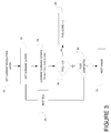
Figure 3 , the process sets the current resolution layer at 30. The subband scores for each of the three subbands used are gathered at 32. These subband scores are combined to get the overall PVQ score for the tile. The individual subband scores may be weighted. In one embodiment, the HH subband score and the LH subband score were each multiplied by 3. This number was derived by experiments and may be changed as desired. - At 36, the combined PVQ is checked to see if it is greater than 1. If so, the PVQ score is set at 1 at 38. In the embodiments here, a PVQ score of 1 indicates an image with no blur, while a score of 0 indicates high blur. The embodiment here is applied one tile at a time. To apply the process to the whole image, the process checks to see if all the tiles are completed at 40. If yes, the process moves on to the next image. If no, the next tile is then accessed at 44 and the process moves on until the entire image is processed.
- The basis of the process of
Figure 3 includes determining a subband score.Figure 4 shows one embodiment of a method of determining a subband score for aparticular subband 50. The process tracks two different counters, one to track the pixel upon which the process operates, the pixel index, and one to track the number of coefficients within the subband. As each subband undergoes processing, these counters are initialized at 52. The pixel value is set equal to the subband data for the pixel corresponding to the pixel index at 54. - At 56, the process determines whether the pixel value is less than a low threshold or higher than a high threshold. The thresholds may be set based upon the type of image data, etc. In one embodiment the low threshold is set at 123 and the high threshold is set to 133 for 8-bit depth input data. If true, the coefficient count is increased at 58 and the pixel index is increased at 60. If not, only the pixel index is increased at 60. At 62, the process checks to see if any pixels remain in the tile that have not been processed. If the pixel index is greater than the number of pixels in the tile, the process completes and the ratio of the number of coefficients/number of pixels becomes the subband score at 64. If not, the pixel continues by returning to 54. This score is then used as the subband score in the process of
Figure 5 . - In this manner, the process can determine automatically the blurriness of the image for a particular layer of resolution. This information can be used to select different types of encoding resident in the encoded data, or to change the layer of the resolution used to generate the final coded image.
- Variations and modification exist. The process can be further optimized by evaluating only those tiles that correspond to foreground regions of the image. The embodiments above focused on the luma component of decoded YUV data, but it could also act on the chroma component.
- Examples provide a method of detecting image quality in a wavelet transform-encoded image, comprising receiving wavelet transform-encoded image data partitioned into tiles at a decoder, each tile partitioned into a number of subbands, evaluating a number of wavelets in fewer than the number of subbands, assigning a measure to each of the subbands evaluated for each tile, using the measures to determine a perceptual visual quality score for the image, and adjusting operation of the decoder based upon the perceptual visual quality score.
- Some examples further comprise assigning a weight to each tile, wherein the weight is based upon a relative importance of the tile in the image.
- In some examples, processing each tile into a number of subbands comprises processing each tile into four subbands.
- In some examples, evaluating the number of wavelets comprises evaluating the number of wavelets in three of the four subbands.
- In some examples, assigning a measure to each of the subbands comprises comparing a number of coefficients to at least one threshold and assigning a measure based upon the comparison.
- In some examples, evaluating the number of wavelets comprises evaluating the number of wavelets in a luminance component of the image data.
- In some examples, evaluating the number of wavelets comprises evaluating the number of wavelets in both a luminance and a chroma component of the image data.
- In some examples, partitioning the image data into tiles occurs in a resolution layer lower than a final resolution of a decoded image.
- In some examples, partitioning the image data into tiles occurs in each of several resolution layers.
- In some examples, evaluating the number of wavelets is performed only on those tiles that correspond to a foreground region of the image date.
- Examples provide a decoding system, comprising a memory to receive wavelet-transformed compressed image data having a predetermined number of subbands, and a decoder to determine a number of wavelet coefficients in a subset of the predetermined number of subbands, measure an amount of blur in the image data based upon the number of wavelet coefficients, and adjust a decoding process based upon the amount of blur.
- Another embodiment includes computer readable code embodied on a computer readable medium that, when executed, causes one or more processors (for example of a computer) to perform any of the above-described operations. As used here, a processor or computer is any device that can execute code. Microprocessors, programmable logic devices, multiprocessor systems, digital signal processors, personal computers, or the like are all examples of such a computer. In some embodiments, the computer readable medium can be a tangible computer readable medium that is configured to store the computer readable code in a non-transitory manner.
- Examples mainly relate to the field of compressed image processing and more particularly to the measurement of visual quality of images, compressed using the JPEG2000 standard.
- Image compression is well known in the art which is used to reduce irrelevance and redundancy of the image data in order to be able to store or transmit data in an efficient form. There are different types of image compression namely BMP (bitmap), PNG (portable Network Graphics), TIFF (Tagged Image File Format), JPEG (Joint Photographic Experts Group), and JPEG 2000 (Joint Photographic Experts Group 2000), etc. The most commonly used techniques are JPEG (Joint Photographic Experts Group), and JPEG 2000 (Joint Photographic Experts Group 2000).
- The JPEG is a commonly used method of lossy compression for digital images, particularly for those images produced by digital photography. One of the characteristics that make the algorithm very flexible is that the compression rate can be adjusted. If one compresses a lot, more information will be lost, but the result image size will be smaller. With a smaller compression rate one can obtain a better quality, but the size of the resulting image will be bigger.
- Presently, JPEG2000 is one of the widely used image compression standards. JPEG2000 (Joint Photographic Experts Group 2000) is a wavelet-based image compression standard. It was created by the Joint Photographic Experts Group committee with the intention of superseding their original discrete cosine transform based JPEG standard. JPEG 2000 has higher compression ratios than JPEG. It does not suffer from the uniform blocks, so characteristics of JPEG images with very high compression rates. Unlike its predecessor, namely the JPEG which is a discrete- cosine-transform (DCT) based standard, JPEG2000 employs wavelet transforms. While it achieves superior performance over JPEG, at high compression ratios JPEG2000 can introduce certain visual artifacts as part of the encoding process. These are primarily the ringing and blurring artifacts.
- From a visual quality perspective, it therefore becomes important to quantify the amount of such artifacts introduced by the compression process. While methods for measuring blurriness in digital images are already proposed, some of them operate in the spatial domain. By detecting edges in an image, they propose to evaluate the local blur at such edges, and then arrive at a global blur estimate for the whole image. Such proposals would need a complete decode of the compressed data. The other methods that operate in the spectral domain, also introduce certain complexities like additional number of transform layers processed, and/or other overheads in the form of edge type analysis and edge sharpness analysis.
- Though both these categories of methods achieve good results in terms of detecting and measuring blurriness, it may not be practical to use them in certain applications that impose a "low-latency" output constraint.
- Therefore there is a need in the art with quicker way of estimating the perceived blurriness in compressed images to solve the above mentioned limitations.
- The above and other aspects, features, and advantages of certain exemplary embodiments of the present invention will be more apparent from the following description taken in conjunction with the accompanying drawings in which:
- Persons skilled in the art will appreciate that elements in the figures are illustrated for simplicity and clarity and may have not been drawn to scale. For example, the dimensions of some of the elements in the figure may be exaggerated relative to other elements to help to improve understanding of various exemplary embodiments of the present disclosure.
- Throughout the drawings, it should be noted that like reference numbers are used to depict the same or similar elements, features, and structures.
- The following description with reference to the accompanying drawings is provided to assist in a comprehensive understanding of exemplary embodiments of the invention as defined by the claims and their equivalents. It includes various specific details to assist in that understanding but these are to be regarded as merely exemplary. Accordingly, those of ordinary skill in the art will recognize that various changes and modifications of the embodiments described herein can be made without departing from the scope of the invention. In addition, descriptions of well-known functions and constructions are omitted for clarity and conciseness.
- The terms and words used in the following description and claims are not limited to the bibliographical meanings, but, are merely used by the inventor to enable a clear and consistent understanding of the invention. Accordingly, it should be apparent to those skilled in the art that the following description of exemplary embodiments of the present invention are provided for illustration purpose only and not for the purpose of limiting the invention.
- It is to be understood that the singular forms "a," "an," and "the" include plural referents unless the context clearly dictates otherwise. The present invention proposes a quick and an efficient heuristic method for measuring the amount of perceived blurriness in a JPEG2000 compressed stream. It obviates the need for a full decode of the compressed image, and instead operates on the wavelet coefficients, prior to any transform. Blur in images is mostly caused by the excessive low pass filtering of data (thereby losing out the high frequency components, and consequently the "details" in the image). A non-blurred image on the other hand, will have enough "details" in the image intact, i.e. a significant presence of edges.
-
Figure 5 shows the Sub-band labeling after one level of wavelet transform according to one embodiment of the present invention. - The figure shows the sub-band labeling after one level of wavelet transform. The wavelet transform of the JPEG2000 standard decomposes the original image into a set of four sub-bands, each with half the original resolution, after one level of transform. The LL subband can then undergo further decomposition, based on the user configuration.
- The labeling convention in
Figure.5 is: - LL: Low pass filtering in both vertical and horizontal directions.
- HL: High pass filtering in horizontal direction and low pass filtering in the vertical direction.
- LH: Low pass filtering in horizontal direction and high pass filtering in the vertical direction.
- HH: High pass filtering in both vertical and horizontal directions.
- JPEG2000 standard partitions the image into "tiles". Tiles are analogous to the 8x8 blocks in the JPEG standard. They are rectangular, and all of them are of the same size. They are coded independently, and represent different regions of the input image.
- In calculating the amount of blurriness in an image, the present invention evaluates the presence of wavelet coefficients in the HH, LH and HL sub-bands, only for the n - 1th resolution layer of each compressed tile.
- Where, "n" corresponds to the resolution of the final decoded image.
- It then assigns to the input image, a real value between 0 and 1 as the PVQ score.
- Where,
- a value of 0 indicates poor quality images with high blur
- a value of 1 indicates a good quality image with very less perceived blur
- A method followed by the present invention is listed below:
- a. Process the n - 1th resolution layer, by setting current layer, N = n - 1
- b. For each tile in the JPEG2000 compressed image,
- i. Evaluate the presence of wavelet coefficients in the HHN sub-band, and assign it to "HHScore".
- ii. Evaluate the presence of wavelet coefficients in the LHN sub-band, and assign it to "LHScore".
- iii. Evaluate the presence of wavelet coefficients in the HLN sub-band, and assign it to "HLScore".
- c. Compute a final weighted "pvqScore" for the entire image, using "HHScore", "LHScore" and "HLScore" from the individual tiles.
- By limiting the evaluation only to the n - 1th layer, the Information would be progressively "lost" due to the two-dimensional low pass filtering in the LL sub-band(s). Moreover, as the resolutions decreases, what remains is mostly the low frequency component of the original image. Looking for presence of high frequency data (or, in other words, for presence of edges) in such components, may only mislead the method. Further, in the lower resolutions, it will mostly be "synthetic" data, after successive transforms - and not the information as it exists in the original layer.
- Since it estimates the blurriness using only one representative resolution and does not employ any transforms, the method can be computationally efficient to calculate the PVQ of a compressed JPEG2000 image. 75% of the final image area will be evaluated for PVQ score (corresponding to the three sub-bands). The method currently proposes PVQ evaluation only in the luminance component of the image.
- It can be further optimized by evaluating for blur only in those tiles that correspond to the foreground region of the image (whenever such information about foreground/background tiles is available). This is relying on the assumption that blurriness is mostly perceived by the human visual system (HVS) in the foreground region of the image, and any blurriness in the background is generally not perceived as an artifact.
-
Figure 6 shows the flowchart of PVQ evaluation process according to one embodiment of the present invention. - The figure shows the flowchart of PVQ evaluation process. For the purpose of simplicity, it assumes only one tile per compressed image. The same process can be repeated over all the tiles that are selected for evaluating blur. In calculating the final weighted "pvqScore", a value of 3.0 was chosen as weights for the HL and LH sub-bands. This was an empirically derived value for one-tile configuration, and may be changed accordingly. In streams where multiple tiles are present, the PVQ scores from individual tiles could be assigned appropriate weights based on their relative importance in the image, to yield a final "pvqScore".
-
Figure 7 shows the flowchart of getSubBandScore () process according to one embodiment of the present invention. - The figure shows the flowchart describing the sub-process, "getSubBandScore ()". It is invoked by providing as input data, the respective sub- bands' wavelet coefficients, and getting as output, the sub-band score. COEFF_LOW_THR and COEFF_HIGH_THR are empirically derived coefficient detection thresholds, and are assigned the values of 123 and 133 respectively, for 8-bit depth input data. Based on image bit-depth, they can be modified accordingly.
Claims (12)
- A method of detecting image quality in a wavelet transform-encoded image, comprising:receiving wavelet transform-encoded image data partitioned into tiles at a decoder, each tile partitioned into a number of subbands;evaluating a number of wavelets in fewer than the number of subbands;assigning a measure to each of the subbands evaluated for each tile;using the measures to determine a perceptual visual quality score for the image; andadjusting operation of the decoder based upon the perceptual visual quality score.
- The method of claim 1, further comprising assigning a weight to each tile, wherein the weight is based upon a relative importance of the tile in the image.
- The method of claim 1 or 2, wherein processing each tile into a number of subbands comprises processing each tile into four subbands.
- The method of claim 3, wherein evaluating the number of wavelets comprises evaluating the number of wavelets in three of the four subbands.
- The method of any preceding claim, wherein assigning a measure to each of the subbands comprises comparing a number of coefficients to at least one threshold and assigning a measure based upon the comparison.
- The method of any preceding claim, wherein evaluating the number of wavelets comprises evaluating the number of wavelets in a luminance component of the image data.
- The method of any preceding claim, wherein evaluating the number of wavelets comprises evaluating the number of wavelets in both a luminance and a chroma component of the image data.
- The method of any preceding claim, wherein partitioning the image data into tiles occurs in a resolution layer lower than a final resolution of a decoded image.
- The method of any preceding claim, wherein partitioning the image data into tiles occurs in each of several resolution layers.
- The method of any preceding claim, wherein evaluating the number of wavelets is performed only on those tiles that correspond to a foreground region of the image date.
- A computer readable medium containing program code instructions which, when executed by one or more processors, cause the one or more processors to perform any of the operations and/or method steps of any of claims 1 to 10.
- A decoding system, comprising:a memory to receive wavelet-transformed compressed image data having a predetermined number of subbands; anda decoder to:determine a number of wavelet coefficients in a subset of the predetermined number of subbands;measure an amount of blur in the image data based upon the number of wavelet coefficients; andadjust a decoding process based upon the amount of blur.
Applications Claiming Priority (2)
| Application Number | Priority Date | Filing Date | Title |
|---|---|---|---|
| IN3766MU2015 | 2015-10-03 | ||
| US15/264,820 US10405002B2 (en) | 2015-10-03 | 2016-09-14 | Low complexity perceptual visual quality evaluation for JPEG2000 compressed streams |
Publications (2)
| Publication Number | Publication Date |
|---|---|
| EP3151565A1 true EP3151565A1 (en) | 2017-04-05 |
| EP3151565B1 EP3151565B1 (en) | 2025-10-01 |
Family
ID=57189754
Family Applications (1)
| Application Number | Title | Priority Date | Filing Date |
|---|---|---|---|
| EP16192071.5A Active EP3151565B1 (en) | 2015-10-03 | 2016-10-03 | A low complexity perceptual visual quality evaluation method for jpeg2000 compressed streams |
Country Status (1)
| Country | Link |
|---|---|
| EP (1) | EP3151565B1 (en) |
Cited By (1)
| Publication number | Priority date | Publication date | Assignee | Title |
|---|---|---|---|---|
| CN113867405A (en) * | 2021-11-09 | 2021-12-31 | 广东电网有限责任公司江门供电局 | Transmission line unmanned aerial vehicle inspection method and system based on 5G network return |
-
2016
- 2016-10-03 EP EP16192071.5A patent/EP3151565B1/en active Active
Non-Patent Citations (5)
| Title |
|---|
| DEEPTI KOUJALAGI ET AL: "BLUR DETECTION OF DIGITAL IMAGES IN REAL-TIME 1", 1 September 2015 (2015-09-01), pages 2393 - 8374, XP055345285, Retrieved from the Internet <URL:http://troindia.in/journal/ijcesr/vol2iss9/53-60.pdf> [retrieved on 20170214] * |
| HANGHANG TONG ET AL: "Blur detection for digital images using wavelet transform", 2004 IEEE INTERNATIONAL CONFERENCE ON MULTIMEDIA AND EXPO : JUNE 27 - 30, 2004, TAIPEI, TAIWAN, IEEE OPERATIONS CENTER, PISCATAWAY, NJ, vol. 1, 27 June 2004 (2004-06-27), pages 17 - 20, XP010770733, ISBN: 978-0-7803-8603-7, DOI: 10.1109/ICME.2004.1394114 * |
| HARISH NARAYANAN RAMAKRISHNAN: "Scholars' Mine Detection and estimation of image blur", 1 December 2010 (2010-12-01), pages 1 - 72, XP055345283, Retrieved from the Internet <URL:http://scholarsmine.mst.edu/cgi/viewcontent.cgi?article=5803&context=masters_theses> [retrieved on 20170214] * |
| MARZILIANO P ET AL: "Perceptual blur and ringing metrics: application to JPEG2000", SIGNAL PROCESSING. IMAGE COMMUNICATION, ELSEVIER SCIENCE PUBLISHERS, AMSTERDAM, NL, vol. 19, no. 2, 1 February 2004 (2004-02-01), pages 163 - 172, XP004483133, ISSN: 0923-5965, DOI: 10.1016/J.IMAGE.2003.08.003 * |
| RABBANI M ET AL: "An overview of the JPEG 2000 still image compression standard", SIGNAL PROCESSING. IMAGE COMMUNICATION, ELSEVIER SCIENCE PUBLISHERS, AMSTERDAM, NL, vol. 17, no. 1, 1 January 2002 (2002-01-01), pages 3 - 48, XP004326797, ISSN: 0923-5965, DOI: 10.1016/S0923-5965(01)00024-8 * |
Cited By (1)
| Publication number | Priority date | Publication date | Assignee | Title |
|---|---|---|---|---|
| CN113867405A (en) * | 2021-11-09 | 2021-12-31 | 广东电网有限责任公司江门供电局 | Transmission line unmanned aerial vehicle inspection method and system based on 5G network return |
Also Published As
| Publication number | Publication date |
|---|---|
| EP3151565B1 (en) | 2025-10-01 |
Similar Documents
| Publication | Publication Date | Title |
|---|---|---|
| Li et al. | Learning convolutional networks for content-weighted image compression | |
| JP3989362B2 (en) | Image processing method based on header information | |
| CN108028941B (en) | Method and apparatus for encoding and decoding digital images by superpixel | |
| TWI519136B (en) | A method, a data processing device and a system for adaptive filtering mechanism to remove encoding artifacts in video data | |
| Walker et al. | Wavelet-based image compression | |
| US9152875B2 (en) | Preserving text quality in video encoding | |
| KR0159434B1 (en) | Wavelet image encoding and decoding device and method using human visual system modeling | |
| US20070291842A1 (en) | Optimal Denoising for Video Coding | |
| CN111432213B (en) | Method and apparatus for tile data size coding for video and image compression | |
| CN115776564B (en) | Methods, apparatus, storage media and electronic devices for transmitting panoramic video | |
| WO2016033725A1 (en) | Block segmentation mode processing method in video coding and relevant apparatus | |
| EP3151565B1 (en) | A low complexity perceptual visual quality evaluation method for jpeg2000 compressed streams | |
| US10405002B2 (en) | Low complexity perceptual visual quality evaluation for JPEG2000 compressed streams | |
| Liu et al. | Sparsity-based soft decoding of compressed images in transform domain | |
| Deshlahra | Analysis of Image Compression Methods Based On Transform and Fractal Coding | |
| TWI226189B (en) | Method for automatically detecting region of interest in the image | |
| US7957607B2 (en) | Decoding apparatus, dequantization method, and computer readable medium storing program thereof | |
| KR20090051438A (en) | Jpec 2000 Compressed Image Quality Evaluation Method Using Context Information | |
| TWI533236B (en) | A method of cs-waveletbased image coding for dvc system | |
| Hasan et al. | Measuring blockiness of videos using edge enhancement filtering | |
| CN120281907A (en) | Video live broadcast system and method | |
| CN113573070A (en) | Image coding method and device and computer storage medium | |
| Hasan et al. | Faster Detection of Independent Lossy Compressed Block Errors in Images and Videos | |
| Schmalz | Digital Images: Compression |
Legal Events
| Date | Code | Title | Description |
|---|---|---|---|
| PUAI | Public reference made under article 153(3) epc to a published international application that has entered the european phase |
Free format text: ORIGINAL CODE: 0009012 |
|
| STAA | Information on the status of an ep patent application or granted ep patent |
Free format text: STATUS: THE APPLICATION HAS BEEN PUBLISHED |
|
| AK | Designated contracting states |
Kind code of ref document: A1 Designated state(s): AL AT BE BG CH CY CZ DE DK EE ES FI FR GB GR HR HU IE IS IT LI LT LU LV MC MK MT NL NO PL PT RO RS SE SI SK SM TR |
|
| AX | Request for extension of the european patent |
Extension state: BA ME |
|
| STAA | Information on the status of an ep patent application or granted ep patent |
Free format text: STATUS: REQUEST FOR EXAMINATION WAS MADE |
|
| 17P | Request for examination filed |
Effective date: 20171005 |
|
| RBV | Designated contracting states (corrected) |
Designated state(s): AL AT BE BG CH CY CZ DE DK EE ES FI FR GB GR HR HU IE IS IT LI LT LU LV MC MK MT NL NO PL PT RO RS SE SI SK SM TR |
|
| STAA | Information on the status of an ep patent application or granted ep patent |
Free format text: STATUS: EXAMINATION IS IN PROGRESS |
|
| 17Q | First examination report despatched |
Effective date: 20201027 |
|
| RAP1 | Party data changed (applicant data changed or rights of an application transferred) |
Owner name: PROJECT GIANTS, LLC |
|
| GRAP | Despatch of communication of intention to grant a patent |
Free format text: ORIGINAL CODE: EPIDOSNIGR1 |
|
| STAA | Information on the status of an ep patent application or granted ep patent |
Free format text: STATUS: GRANT OF PATENT IS INTENDED |
|
| RIC1 | Information provided on ipc code assigned before grant |
Ipc: G06T 7/00 20170101ALI20250328BHEP Ipc: G06T 5/73 20240101ALI20250328BHEP Ipc: H04N 19/86 20140101ALI20250328BHEP Ipc: H04N 19/44 20140101ALI20250328BHEP Ipc: H04N 19/63 20140101AFI20250328BHEP |
|
| INTG | Intention to grant announced |
Effective date: 20250422 |
|
| GRAS | Grant fee paid |
Free format text: ORIGINAL CODE: EPIDOSNIGR3 |
|
| GRAA | (expected) grant |
Free format text: ORIGINAL CODE: 0009210 |
|
| STAA | Information on the status of an ep patent application or granted ep patent |
Free format text: STATUS: THE PATENT HAS BEEN GRANTED |
|
| AK | Designated contracting states |
Kind code of ref document: B1 Designated state(s): AL AT BE BG CH CY CZ DE DK EE ES FI FR GB GR HR HU IE IS IT LI LT LU LV MC MK MT NL NO PL PT RO RS SE SI SK SM TR |
|
| REG | Reference to a national code |
Ref country code: GB Ref legal event code: FG4D Ref country code: CH Ref legal event code: F10 Free format text: ST27 STATUS EVENT CODE: U-0-0-F10-F00 (AS PROVIDED BY THE NATIONAL OFFICE) Effective date: 20251001 |
|
| REG | Reference to a national code |
Ref country code: IE Ref legal event code: FG4D |
|
| REG | Reference to a national code |
Ref country code: DE Ref legal event code: R096 Ref document number: 602016093696 Country of ref document: DE |
|
| REG | Reference to a national code |
Ref country code: NL Ref legal event code: MP Effective date: 20251001 |
|
| REG | Reference to a national code |
Ref country code: AT Ref legal event code: MK05 Ref document number: 1843823 Country of ref document: AT Kind code of ref document: T Effective date: 20251001 |
|
| PG25 | Lapsed in a contracting state [announced via postgrant information from national office to epo] |
Ref country code: NL Free format text: LAPSE BECAUSE OF FAILURE TO SUBMIT A TRANSLATION OF THE DESCRIPTION OR TO PAY THE FEE WITHIN THE PRESCRIBED TIME-LIMIT Effective date: 20251001 |
|
| PG25 | Lapsed in a contracting state [announced via postgrant information from national office to epo] |
Ref country code: ES Free format text: LAPSE BECAUSE OF FAILURE TO SUBMIT A TRANSLATION OF THE DESCRIPTION OR TO PAY THE FEE WITHIN THE PRESCRIBED TIME-LIMIT Effective date: 20251001 |
|
| REG | Reference to a national code |
Ref country code: LT Ref legal event code: MG9D |
|
| PG25 | Lapsed in a contracting state [announced via postgrant information from national office to epo] |
Ref country code: NO Free format text: LAPSE BECAUSE OF FAILURE TO SUBMIT A TRANSLATION OF THE DESCRIPTION OR TO PAY THE FEE WITHIN THE PRESCRIBED TIME-LIMIT Effective date: 20260101 |
|
| PG25 | Lapsed in a contracting state [announced via postgrant information from national office to epo] |
Ref country code: AT Free format text: LAPSE BECAUSE OF FAILURE TO SUBMIT A TRANSLATION OF THE DESCRIPTION OR TO PAY THE FEE WITHIN THE PRESCRIBED TIME-LIMIT Effective date: 20251001 Ref country code: FI Free format text: LAPSE BECAUSE OF FAILURE TO SUBMIT A TRANSLATION OF THE DESCRIPTION OR TO PAY THE FEE WITHIN THE PRESCRIBED TIME-LIMIT Effective date: 20251001 Ref country code: HR Free format text: LAPSE BECAUSE OF FAILURE TO SUBMIT A TRANSLATION OF THE DESCRIPTION OR TO PAY THE FEE WITHIN THE PRESCRIBED TIME-LIMIT Effective date: 20251001 |
|
| PG25 | Lapsed in a contracting state [announced via postgrant information from national office to epo] |
Ref country code: RS Free format text: LAPSE BECAUSE OF FAILURE TO SUBMIT A TRANSLATION OF THE DESCRIPTION OR TO PAY THE FEE WITHIN THE PRESCRIBED TIME-LIMIT Effective date: 20260101 |
|
| PG25 | Lapsed in a contracting state [announced via postgrant information from national office to epo] |
Ref country code: IS Free format text: LAPSE BECAUSE OF FAILURE TO SUBMIT A TRANSLATION OF THE DESCRIPTION OR TO PAY THE FEE WITHIN THE PRESCRIBED TIME-LIMIT Effective date: 20260201 |
|
| PG25 | Lapsed in a contracting state [announced via postgrant information from national office to epo] |
Ref country code: CZ Free format text: LAPSE BECAUSE OF FAILURE TO SUBMIT A TRANSLATION OF THE DESCRIPTION OR TO PAY THE FEE WITHIN THE PRESCRIBED TIME-LIMIT Effective date: 20251001 Ref country code: PT Free format text: LAPSE BECAUSE OF FAILURE TO SUBMIT A TRANSLATION OF THE DESCRIPTION OR TO PAY THE FEE WITHIN THE PRESCRIBED TIME-LIMIT Effective date: 20260202 |
|
| PG25 | Lapsed in a contracting state [announced via postgrant information from national office to epo] |
Ref country code: PL Free format text: LAPSE BECAUSE OF FAILURE TO SUBMIT A TRANSLATION OF THE DESCRIPTION OR TO PAY THE FEE WITHIN THE PRESCRIBED TIME-LIMIT Effective date: 20251001 |
|
| PG25 | Lapsed in a contracting state [announced via postgrant information from national office to epo] |
Ref country code: LV Free format text: LAPSE BECAUSE OF FAILURE TO SUBMIT A TRANSLATION OF THE DESCRIPTION OR TO PAY THE FEE WITHIN THE PRESCRIBED TIME-LIMIT Effective date: 20251001 |
|
| PG25 | Lapsed in a contracting state [announced via postgrant information from national office to epo] |
Ref country code: BG Free format text: LAPSE BECAUSE OF FAILURE TO SUBMIT A TRANSLATION OF THE DESCRIPTION OR TO PAY THE FEE WITHIN THE PRESCRIBED TIME-LIMIT Effective date: 20251001 |
|
| REG | Reference to a national code |
Ref country code: DE Ref legal event code: R119 Ref document number: 602016093696 Country of ref document: DE |
|
| REG | Reference to a national code |
Ref country code: CH Ref legal event code: H13 Free format text: ST27 STATUS EVENT CODE: U-0-0-H10-H13 (AS PROVIDED BY THE NATIONAL OFFICE) Effective date: 20260527 |
|
| PG25 | Lapsed in a contracting state [announced via postgrant information from national office to epo] |
Ref country code: RO Free format text: LAPSE BECAUSE OF FAILURE TO SUBMIT A TRANSLATION OF THE DESCRIPTION OR TO PAY THE FEE WITHIN THE PRESCRIBED TIME-LIMIT Effective date: 20251001 |
|
| PG25 | Lapsed in a contracting state [announced via postgrant information from national office to epo] |
Ref country code: LU Free format text: LAPSE BECAUSE OF NON-PAYMENT OF DUE FEES Effective date: 20251003 |
|
| REG | Reference to a national code |
Ref country code: BE Ref legal event code: MM Effective date: 20251031 |
|
| PG25 | Lapsed in a contracting state [announced via postgrant information from national office to epo] |
Ref country code: LT Free format text: LAPSE BECAUSE OF FAILURE TO SUBMIT A TRANSLATION OF THE DESCRIPTION OR TO PAY THE FEE WITHIN THE PRESCRIBED TIME-LIMIT Effective date: 20251001 |
|
| PG25 | Lapsed in a contracting state [announced via postgrant information from national office to epo] |
Ref country code: MC Free format text: LAPSE BECAUSE OF FAILURE TO SUBMIT A TRANSLATION OF THE DESCRIPTION OR TO PAY THE FEE WITHIN THE PRESCRIBED TIME-LIMIT Effective date: 20251001 |
|
| PG25 | Lapsed in a contracting state [announced via postgrant information from national office to epo] |
Ref country code: SM Free format text: LAPSE BECAUSE OF FAILURE TO SUBMIT A TRANSLATION OF THE DESCRIPTION OR TO PAY THE FEE WITHIN THE PRESCRIBED TIME-LIMIT Effective date: 20251001 |
|
| PG25 | Lapsed in a contracting state [announced via postgrant information from national office to epo] |
Ref country code: DK Free format text: LAPSE BECAUSE OF FAILURE TO SUBMIT A TRANSLATION OF THE DESCRIPTION OR TO PAY THE FEE WITHIN THE PRESCRIBED TIME-LIMIT Effective date: 20251001 |
|
| PG25 | Lapsed in a contracting state [announced via postgrant information from national office to epo] |
Ref country code: IT Free format text: LAPSE BECAUSE OF FAILURE TO SUBMIT A TRANSLATION OF THE DESCRIPTION OR TO PAY THE FEE WITHIN THE PRESCRIBED TIME-LIMIT Effective date: 20251001 |
|
| PG25 | Lapsed in a contracting state [announced via postgrant information from national office to epo] |
Ref country code: DE Free format text: LAPSE BECAUSE OF NON-PAYMENT OF DUE FEES Effective date: 20260501 |
|
| PG25 | Lapsed in a contracting state [announced via postgrant information from national office to epo] |
Ref country code: CH Free format text: LAPSE BECAUSE OF NON-PAYMENT OF DUE FEES Effective date: 20251031 Ref country code: BE Free format text: LAPSE BECAUSE OF NON-PAYMENT OF DUE FEES Effective date: 20251031 |
|
| PG25 | Lapsed in a contracting state [announced via postgrant information from national office to epo] |
Ref country code: EE Free format text: LAPSE BECAUSE OF FAILURE TO SUBMIT A TRANSLATION OF THE DESCRIPTION OR TO PAY THE FEE WITHIN THE PRESCRIBED TIME-LIMIT Effective date: 20251001 |
|
| PG25 | Lapsed in a contracting state [announced via postgrant information from national office to epo] |
Ref country code: SK Free format text: LAPSE BECAUSE OF FAILURE TO SUBMIT A TRANSLATION OF THE DESCRIPTION OR TO PAY THE FEE WITHIN THE PRESCRIBED TIME-LIMIT Effective date: 20251001 |
|
| PG25 | Lapsed in a contracting state [announced via postgrant information from national office to epo] |
Ref country code: SE Free format text: LAPSE BECAUSE OF FAILURE TO SUBMIT A TRANSLATION OF THE DESCRIPTION OR TO PAY THE FEE WITHIN THE PRESCRIBED TIME-LIMIT Effective date: 20251001 |
|
| PLBE | No opposition filed within time limit |
Free format text: ORIGINAL CODE: 0009261 |
|
| STAA | Information on the status of an ep patent application or granted ep patent |
Free format text: STATUS: NO OPPOSITION FILED WITHIN TIME LIMIT |
|
| REG | Reference to a national code |
Ref country code: CH Ref legal event code: L10 Free format text: ST27 STATUS EVENT CODE: U-0-0-L10-L00 (AS PROVIDED BY THE NATIONAL OFFICE) Effective date: 20260812 |