EP3151539A1 - Image acquisition device, image acquisition method and terminal - Google Patents
Image acquisition device, image acquisition method and terminal Download PDFInfo
- Publication number
- EP3151539A1 EP3151539A1 EP15800509.0A EP15800509A EP3151539A1 EP 3151539 A1 EP3151539 A1 EP 3151539A1 EP 15800509 A EP15800509 A EP 15800509A EP 3151539 A1 EP3151539 A1 EP 3151539A1
- Authority
- EP
- European Patent Office
- Prior art keywords
- cameras
- image
- brightness
- images
- image acquisition
- Prior art date
- Legal status (The legal status is an assumption and is not a legal conclusion. Google has not performed a legal analysis and makes no representation as to the accuracy of the status listed.)
- Granted
Links
Images



Classifications
-
- H—ELECTRICITY
- H04—ELECTRIC COMMUNICATION TECHNIQUE
- H04N—PICTORIAL COMMUNICATION, e.g. TELEVISION
- H04N23/00—Cameras or camera modules comprising electronic image sensors; Control thereof
- H04N23/70—Circuitry for compensating brightness variation in the scene
- H04N23/76—Circuitry for compensating brightness variation in the scene by influencing the image signals
-
- G—PHYSICS
- G06—COMPUTING OR CALCULATING; COUNTING
- G06T—IMAGE DATA PROCESSING OR GENERATION, IN GENERAL
- G06T5/00—Image enhancement or restoration
- G06T5/70—Denoising; Smoothing
-
- G—PHYSICS
- G06—COMPUTING OR CALCULATING; COUNTING
- G06T—IMAGE DATA PROCESSING OR GENERATION, IN GENERAL
- G06T5/00—Image enhancement or restoration
- G06T5/50—Image enhancement or restoration using two or more images, e.g. averaging or subtraction
-
- H—ELECTRICITY
- H04—ELECTRIC COMMUNICATION TECHNIQUE
- H04N—PICTORIAL COMMUNICATION, e.g. TELEVISION
- H04N23/00—Cameras or camera modules comprising electronic image sensors; Control thereof
- H04N23/45—Cameras or camera modules comprising electronic image sensors; Control thereof for generating image signals from two or more image sensors being of different type or operating in different modes, e.g. with a CMOS sensor for moving images in combination with a charge-coupled device [CCD] for still images
-
- H—ELECTRICITY
- H04—ELECTRIC COMMUNICATION TECHNIQUE
- H04N—PICTORIAL COMMUNICATION, e.g. TELEVISION
- H04N23/00—Cameras or camera modules comprising electronic image sensors; Control thereof
- H04N23/60—Control of cameras or camera modules
- H04N23/63—Control of cameras or camera modules by using electronic viewfinders
-
- H—ELECTRICITY
- H04—ELECTRIC COMMUNICATION TECHNIQUE
- H04N—PICTORIAL COMMUNICATION, e.g. TELEVISION
- H04N23/00—Cameras or camera modules comprising electronic image sensors; Control thereof
- H04N23/70—Circuitry for compensating brightness variation in the scene
-
- H—ELECTRICITY
- H04—ELECTRIC COMMUNICATION TECHNIQUE
- H04N—PICTORIAL COMMUNICATION, e.g. TELEVISION
- H04N23/00—Cameras or camera modules comprising electronic image sensors; Control thereof
- H04N23/70—Circuitry for compensating brightness variation in the scene
- H04N23/71—Circuitry for evaluating the brightness variation
-
- H—ELECTRICITY
- H04—ELECTRIC COMMUNICATION TECHNIQUE
- H04N—PICTORIAL COMMUNICATION, e.g. TELEVISION
- H04N23/00—Cameras or camera modules comprising electronic image sensors; Control thereof
- H04N23/80—Camera processing pipelines; Components thereof
-
- H—ELECTRICITY
- H04—ELECTRIC COMMUNICATION TECHNIQUE
- H04N—PICTORIAL COMMUNICATION, e.g. TELEVISION
- H04N23/00—Cameras or camera modules comprising electronic image sensors; Control thereof
- H04N23/80—Camera processing pipelines; Components thereof
- H04N23/81—Camera processing pipelines; Components thereof for suppressing or minimising disturbance in the image signal generation
-
- H—ELECTRICITY
- H04—ELECTRIC COMMUNICATION TECHNIQUE
- H04N—PICTORIAL COMMUNICATION, e.g. TELEVISION
- H04N23/00—Cameras or camera modules comprising electronic image sensors; Control thereof
- H04N23/95—Computational photography systems, e.g. light-field imaging systems
- H04N23/957—Light-field or plenoptic cameras or camera modules
-
- H—ELECTRICITY
- H04—ELECTRIC COMMUNICATION TECHNIQUE
- H04N—PICTORIAL COMMUNICATION, e.g. TELEVISION
- H04N5/00—Details of television systems
- H04N5/222—Studio circuitry; Studio devices; Studio equipment
- H04N5/262—Studio circuits, e.g. for mixing, switching-over, change of character of image, other special effects ; Cameras specially adapted for the electronic generation of special effects
- H04N5/2621—Cameras specially adapted for the electronic generation of special effects during image pickup, e.g. digital cameras, camcorders, video cameras having integrated special effects capability
-
- H—ELECTRICITY
- H04—ELECTRIC COMMUNICATION TECHNIQUE
- H04N—PICTORIAL COMMUNICATION, e.g. TELEVISION
- H04N5/00—Details of television systems
- H04N5/222—Studio circuitry; Studio devices; Studio equipment
- H04N5/262—Studio circuits, e.g. for mixing, switching-over, change of character of image, other special effects ; Cameras specially adapted for the electronic generation of special effects
- H04N5/2624—Studio circuits, e.g. for mixing, switching-over, change of character of image, other special effects ; Cameras specially adapted for the electronic generation of special effects for obtaining an image which is composed of whole input images, e.g. splitscreen
-
- H—ELECTRICITY
- H04—ELECTRIC COMMUNICATION TECHNIQUE
- H04N—PICTORIAL COMMUNICATION, e.g. TELEVISION
- H04N5/00—Details of television systems
- H04N5/222—Studio circuitry; Studio devices; Studio equipment
- H04N5/262—Studio circuits, e.g. for mixing, switching-over, change of character of image, other special effects ; Cameras specially adapted for the electronic generation of special effects
- H04N5/265—Mixing
-
- G—PHYSICS
- G06—COMPUTING OR CALCULATING; COUNTING
- G06T—IMAGE DATA PROCESSING OR GENERATION, IN GENERAL
- G06T2207/00—Indexing scheme for image analysis or image enhancement
- G06T2207/20—Special algorithmic details
- G06T2207/20212—Image combination
- G06T2207/20221—Image fusion; Image merging
-
- H—ELECTRICITY
- H04—ELECTRIC COMMUNICATION TECHNIQUE
- H04N—PICTORIAL COMMUNICATION, e.g. TELEVISION
- H04N23/00—Cameras or camera modules comprising electronic image sensors; Control thereof
- H04N23/70—Circuitry for compensating brightness variation in the scene
- H04N23/741—Circuitry for compensating brightness variation in the scene by increasing the dynamic range of the image compared to the dynamic range of the electronic image sensors
Definitions
- the present invention relates to the field of terminal shooting, and more particularly, to an image acquisition device, an image acquisition method and an image acquisition terminal, which can enhance image brightness in dark light conditions.
- Environmental illumination is a physical quantity that is used to reflect light and shade degree of environments in which an object is located, and is equal to the luminous flux through the unit area vertically in numerical.
- the unit of illumination is the Lux, and 1 Lux is equal to the illumination generated by 1 lumen of luminous flux shining on 1 square meter surface.
- the environment illumination is relatively small, such as less than 10 Lux, the environment is regarded as a dark light environment.
- the brightness of shot images may reduce, and the image as a whole is black and blurring.
- a method of increasing exposure time is usually adopted.
- a terminal such as a mobile phone is usually held by the hand in use, and in the process of exposure, the image registration is not executed, which is easy to cause the images blurring in the process of long exposure.
- the present disclosure aims to provide an image acquisition device, an image acquisition method and a terminal, so as to solve the problem of images shot in a dark light environment to be blurring in the existing technology.
- the present disclosure provides an image acquisition device, two image acquisition methods and an image acquisition terminal.
- the image acquisition device includes a camera shooting module, a control module and a processing module, wherein, the camera shooting module includes at least two cameras; the control module is configured to control the at least two cameras of the camera shooting module to shoot the same scenario to obtain at least two images; and the processing module is configured to process the at least two images shot by the at least two cameras of the camera shooting module for the same scenario, so as to obtain an image with enhanced brightness.
- the processing module includes a correction unit, a denoising unit and a brightness superposition unit.
- the correction unit is configured to correct the at least two images shot simultaneously by the at least two cameras for the same scenario according to a distance between the at least two cameras and a location relationship of the at least two cameras.
- the denoising unit is configured to remove noises in at least two corrected images shot simultaneously by the at least two cameras.
- the brightness superposition unit is configured to superpose the brightness of corresponding pixel points in the at least two images shot simultaneously by the at least two cameras, so as to obtain an image with enhanced brightness.
- control module includes a dark light judgment unit and a control unit.
- the dark light judgment unit is configured to detect the environment illumination while shooting and determine the shooting environment is a dark light environment when the environment illumination is smaller than a preset threshold value.
- the control unit is configured to control the at least two cameras to shoot the same scenario simultaneously on the basis that the dark light judgment unit determines the shooting environment is the dark light environment.
- the control unit is further configured to control the at least two cameras to continuously shoot the same scenario simultaneously to obtain at least two images on the basis that a continuous shooting instruction is received.
- the processing module includes a correction unit, a denoising unit and a brightness superposition unit.
- the correction unit is configured to correct the at least two images shot simultaneously by the at least two cameras every time.
- the denoising unit is configured to remove noises in at least two corrected images shot simultaneously by the at least two cameras every time.
- the brightness superposition unit is configured to superpose the brightness of the pixel points in at least two images shot currently by the at least two cameras with the brightness of corresponding pixel points in the image with enhanced brightness obtained by superposing at least two images shot by the at least two cameras last time, so as to obtain an image with enhanced brightness after multiple shootings.
- the image acquisition device further includes a display module.
- the display module is configured to display the image with enhanced brightness obtained after each shooting.
- An image acquisition method applied to the image acquisition device includes:
- the image acquisition method further includes the steps of determining whether a shooting environment is a dark light environment or not and controlling the at least two cameras to shoot the same scenario when the shooting environment is the dark light environment.
- An image acquisition method applied to an image acquisition device includes:
- the image acquisition terminal includes a processor, a memory and a camera shooting module.
- the camera shooting module includes at least two cameras.
- the memory stores a group of program codes.
- the processor is configured to call the program codes stored in the memory to execute for:
- the processor calling the program codes stored in the memory to execute for processing the at least two images shot by the at least two cameras for the same scenario, so as to obtain an image with enhanced brightness includes:
- the processor calling the program codes stored in the memory to execute for controlling at least two cameras to shoot the same scenario to obtain at least two images includes:
- the processor calls the program codes stored in the memory to further executes for:
- the processor calling the program codes stored in the memory to execute for processing the at least two images shot by the at least two cameras for the same scenario, so as to obtain an image with enhanced brightness includes:
- the processor calls the program codes stored in the memory to further executes for:
- the image acquisition device, the image acquisition methods and the image acquisition terminal provided in the present disclosure employ at least two cameras.
- the control module can control the at least two cameras to shoot the same scenario simultaneously to obtain at least two images; and the processing module can process the at least two images, so as to obtain an image with enhanced brightness. Therefore, the image acquisition device, the image acquisition methods and the image acquisition terminal provided in the present disclosure can obtain an image with enhanced brightness in a dark light environment.
- the at least two cameras in the present disclosure can be controlled to shoot the same scenario simultaneously, which can solve the problem of obtained images to be blurring due to increasing exposure time in the existing technology.
- FIG. 1 is a block diagram of an image acquisition device 100 according to an embodiment of the present disclosure.
- the image acquisition device 100 in this embodiment can be applied to a mobile phone, a table computer, and other intelligent devices.
- the shooting referred in the present disclosure includes, but not limited to, taking pictures, recording video, and so on. Taking pictures is taken here as an example to describe the present disclosure. It should be understood that a video can be obtained by multiple pictures according to time order, namely, the present disclosure also applies to video shooting.
- the image acquisition device 100 includes a camera shooting module 110, a control module 120, a processing module 130 and a display module 140.
- the camera shooting module 110 can be a camera shooting module in a mobile phone or other terminals, and it is configured for image sampling (e.g., taking pictures, recording videos) for an external scenario.
- the camera shooting module 110 includes at least two cameras.
- the camera shooting module 110 includes two cameras.
- the two cameras have the same resolution.
- the two cameras are located adjacent to each other.
- the distance of the two cameras should be as short as possible if the condition allows, so that when the two cameras shoot the same scenario, the images shot by the two cameras can be matched as many as possible.
- the control module 120 is configured to control the camera shooting module 110 to shoot the scenario.
- the control module 120 determines whether a shooting environment is a dark light environment or not, and controls the camera shooting module 110 to shoot. In detail, when the shooting environment is a dark light environment, the control module 120 controls the two cameras of the camera shooting module 110 to shoot the same scenario simultaneously, otherwise, the control module 120 controls one of the two cameras of the camera shooting module 110 to shoot.
- the control module 120 is also configured to, according to a continuous shooting instruction of a user, control the two cameras to continuously shoot the same scenario simultaneously in the dark light environment, namely, the control module 120 is configured to control each of the two cameras to conduct multiple shootings. In the process of multiple shootings, the control module 120 can control the two cameras to shoot simultaneously for each shooting.
- the control module 120 can include a dark light judgment unit 121 and a control unit 122.
- the dark light judgment unit 121 is configured to detect the environment illumination while shooting. When the environment illumination is smaller than a preset threshold value, the dark light judgment unit 121 determines the shooting environment is a dark light environment. When the environment illumination is greater than the preset threshold value, the dark judgment unit 121 determines the shooting environment is a normal environment.
- the control unit 122 is configured to start a dark light shooting mode when the dark light judgment unit 121 determines the shooting environment is the dark light environment, namely, the control unit 122 controls the two cameras to shoot the same scenario simultaneously.
- the control unit 122 starts a normal shooting mode, namely, the control unit 122 controls one camera of the two cameras of the camera shooting module 110 to shoot.
- the processing module 130 is configured to process images shot by the camera shooting module 110 for the same scenario, so as to obtain an image with enhanced brightness.
- the processing module 130 can include a correction unit 131, a denoising unit 132 and a brightness superposition unit 133.
- the correction unit 131 is configured to correct the images shot simultaneously by the two cameras for the same scenario according to a distance between the two cameras and a location relationship of the two cameras, so as to make two images coincide. Namely, after correction, the same shooting object is located at the same location in the two images shot by the two cameras, that is, the location of a shooting object in the image shot by one camera of the two cameras is the same as the location of the shooting object in the image shot by another camera of the two cameras.
- the correction unit 131 corrects images employing the following method: firstly, determining three points A, B and C on the surface which is H1 away from both the two cameras and is perpendicular to the optical axis, and obtaining images shot simultaneously by the two cameras; determining the corresponding imaging points are A0, B0 and C0 respectively in the image shot by one camera of the two cameras; and determining the corresponding imaging points are A1, B1 and C1 respectively in the image shot by another camera of the two cameras.
- the coordinates (namely, the location of the points in the image) of the above six pixel points are known, so the values of correction parameters m, n, k1, k2, k3 and k4 can be calculated.
- the correction parameters of different surfaces where the distances between each surface and the cameras are different can be calculated. And the correction parameters corresponding to different surfaces where the distances between each surface and the cameras are different can be stored so as to obtain a corresponding relationship between the correction parameters and the surfaces. Therefore, when the two cameras are employed to shoot simultaneously, the image acquisition device 100 can obtain the pixel point in the image shot by another camera of the two cameras corresponding to a pixel point in the image shot by one camera of the two cameras. By moving one image of the two images shot by the two cameras, the pixel points of the two images can completely correspond, so as to achieve to correct the two images.
- the denoising unit 132 is configured to remove noises in two corrected images shot simultaneously by the two cameras.
- the denoising unit 132 can adopt a denoising method to remove the noise.
- the denoising unit 132 adopts the following method to remove the noise: firstly, obtaining the brightness value of each pixel point in the two corrected images shot simultaneously by the two cameras; and setting the corresponding pixel points in the two images shot simultaneously by the two cameras, where the difference of whose brightness value or color value is greater than a preset threshold value, to be the noises; finally, removing the noises in the two images respectively, and generating the brightness and the color of the pixel points located at the noises according to brightness information and the color value of the pixel points around the noises.
- the brightness superposition unit 133 is configured to superpose the brightness of corresponding pixel points in the two images shot simultaneously by the two cameras, so as to obtain an image with enhanced brightness.
- the correction unit 131 corrects the two images shot simultaneously by the two cameras for each shooting.
- the denoising unit 132 is configured to remove the noises in the two corrected images shot simultaneously by the two cameras for each shooting.
- the brightness superposition unit 133 is configured to superpose the brightness of the pixel points in the two images shot currently by the two cameras with the brightness of corresponding pixel points in the image with enhanced brightness obtained by superposing the two images shot by the two cameras last time, so as to obtain an image with enhanced brightness. Namely, after a first shooting, the brightness superposition unit 133 superposes the brightness of corresponding pixel points in the images shot by the two cameras for the first time only, thereby obtaining an image with enhanced brightness after the first shooting.
- the brightness superposition unit 133 superposes the brightness of the pixel points in the images shot by the two cameras for the second time with the brightness of corresponding pixel points in the image with enhanced brightness obtained after the first shooting, so as to obtain an image with enhanced brightness after the second shooting.
- the display module 140 is configured to display the image with enhanced brightness processed by the processing module 130. Understandably, when the two cameras conduct multiple continuous shootings, the display module 140 is configured to display the image with enhanced brightness obtained after each shooting, so that a photographer can directly observe the image with enhanced brightness obtained after multiple shootings and processing.
- control module 120 can control the two cameras to stop continuous shootings. Understandably, in the case of a normal shooting mode, the display module 140 is further configured to display the images shot by one camera of the two cameras of the camera shooting module 110.
- the image acquisition device 100 provided in the technical solution includes two cameras.
- the control module 120 can control the two cameras to shoot the same scenario simultaneously to obtain two images; and the processing module 130 can process the two images, so as to obtain an image with enhanced brightness. Therefore, the image acquisition device 100 provided in the technical solution can obtain an image with enhanced brightness in a dark light environment.
- the two cameras provided in the technical solution can be controlled to shoot the same scenario simultaneously, which can solve the problem of obtained images to be blurring due to increasing exposure time in the existing technology.
- the present disclosure also provides an image acquisition method, and the image acquisition method can be realized by the image acquisition device 100 provided by the embodiment of the technical solution as shown in FIG. 1 .
- the image acquisition method includes the following steps.
- Step S101 determining whether a shooting environment is a dark light environment or not.
- the dark light judgment unit 121 can detect the environment illumination while shooting. When the environment illumination is smaller than a preset threshold value, the dark light judgment unit 121 determines the shooting environment is a dark light environment. When the environment illumination is greater than the preset threshold value, the dark judgment unit 121 determines the shooting environment is a normal environment.
- Step S102 controlling two cameras of the image acquisition device to shoot the same scenario simultaneously to obtain two images when the shooting environment is the dark light environment.
- the control unit 122 When the dark light judgment unit 121 determines the shooting environment is the dark light environment, the control unit 122 starts a dark light shooting mode, namely, the control unit 122 controls the two cameras to shoot the same scenario simultaneously.
- the control unit 122 starts a normal shooting mode, namely, the control unit 122 controls one camera of the two cameras to shoot, and the shooting could be stopped after obtaining the shot images.
- Step S103 processing the two images shot simultaneously by the two cameras for the same scenario, so as to obtain an image with enhanced brightness.
- step S103 can include the following steps:
- the denoising unit 132 removes noises in two corrected images shot simultaneously by the two cameras.
- the denoising unit 132 can adopt a denoising method to remove the noise.
- the denoising unit 132 adopts the following method to remove the noise: firstly, obtaining the brightness value of each pixel point in the two corrected images shot simultaneously by the two cameras; and setting the corresponding pixel points in the two images shot simultaneously by the two cameras, where the difference of whose brightness value or color value is greater than a preset threshold value, to be the noises; finally, removing the noises in the two images respectively, and generating the brightness and the color of the pixel points located at the noises according to brightness information and the color value of the pixel points around the noises.
- the brightness superposition unit 133 superposes the brightness of corresponding pixel points in the two images shot simultaneously by the two cameras, so as to obtain an image with enhanced brightness. Namely, the brightness superposition unit 133 superposes the brightness value of the corresponding pixel points in the two images to obtain the brightness value of the pixel points in an image with enhanced brightness, so the brightness value of the pixel points in the image with enhanced brightness is approximately equal to the double of the brightness value of each original image of the two images shot by the two cameras.
- Step S104 displaying the image with enhanced brightness.
- the image acquisition method can also include a step of storing the image with enhanced brightness.
- the image acquisition method provided by this embodiment can not include the step of determining whether a shooting environment is a dark light environment or not.
- the camera shooting module 110 including two cameras is taken here as an example.
- the image acquisition device 100 can also control the more than two cameras to shoot simultaneously, and process the images shot by the more than two cameras, so as to obtain an image with enhanced brightness.
- the image acquisition device 100 provided in the technical solution includes two cameras.
- the control module 120 can control the two cameras to shoot the same scenario simultaneously to obtain two images; and the processing module 130 can process the two images, so as to obtain an image with enhanced brightness. Therefore, the image acquisition device 100 provided in the technical solution can obtain an image with enhanced brightness in a dark light environment.
- the two cameras provided in the technical solution can be controlled to shoot the same scenario simultaneously, which can solve the problem of obtained images to be blurring due to increasing exposure time in the existing technology.
- Another embodiment of the technical solution also provides an image acquisition method, and the image acquisition method can be realized by the image acquisition device 100 provided by the embodiment of the technical solution as shown in FIG. 1 .
- the image acquisition method includes the following steps.
- Step S201 determining whether a shooting environment is a dark light environment or not.
- the dark light judgment unit 121 can detect the environment illumination while shooting. When the environment illumination is smaller than a preset threshold value, the dark light judgment unit 121 determines the shooting environment is a dark light environment. When the environment illumination is greater than the preset threshold value, the dark judgment unit 121 determines the shooting environment is a normal environment.
- Step S202 controlling two cameras of the image acquisition device to shoot the same scenario simultaneously to obtain two images when the shooting environment is the dark light environment.
- the control unit 122 When the dark light judgment unit 121 determines the shooting environment is the dark light environment, the control unit 122 starts a dark light shooting mode, namely, the control unit 122 controls the two cameras to shoot the same scenario simultaneously.
- the control unit 122 starts a normal shooting mode, namely, the control unit 122 controls one camera of the two cameras to shoot, and the shooting could be stopped after obtaining the shot images.
- Step S203 processing the two images shot simultaneously by the two cameras for the same scenario, so as to obtain an image with enhanced brightness.
- step S203 can include the following steps:
- the denoising unit 132 removes noises in two corrected images shot simultaneously by the two cameras.
- the denoising unit 132 can adopt a denoising method to remove the noise.
- the denoising unit 132 adopts the following method to remove the noise: firstly, obtaining the brightness value of each pixel point in the two corrected images shot simultaneously by the two cameras; and setting the corresponding pixel points in the two images shot simultaneously by the two cameras, where the difference of whose brightness value or color value is greater than a preset threshold value, to be the noises; finally, removing the noises in the two images respectively, and generating the brightness and the color of the pixel points located at the noises according to brightness information and the color value of the pixel points around the noises.
- the brightness superposition unit 133 superposes the brightness of corresponding pixel points in the two images shot simultaneously by the two cameras, so as to obtain an image with enhanced brightness. Namely, the brightness superposition unit 133 superposes the brightness value of the corresponding pixel points in the two images to obtain the brightness value of the pixel points in an image with enhanced brightness, so the brightness value of the pixel points in the image with enhanced brightness is approximately equal to the double of the brightness value of each original image of the two images shot by the two cameras.
- the step S203 can also include a step of displaying the image with enhanced brightness after the first shooting.
- Step S204 determining whether a continuous shooting instruction is received or not, and conducting a continuous shooting to obtain multi-frame images if the continuous shooting instruction is received, and processing the multi-frame images to obtain an image with enhanced brightness, and displaying the image with enhanced brightness.
- the image acquisition device 100 processes two images shot by the two cameras every time, and superposes the two images with the image with enhanced brightness obtained last time, so as to obtain an image with enhanced brightness after each shooting. Furthermore, the image acquisition device 100 displays each image with enhanced brightness obtained after each shooting. When the continuous shooting stops, a final image with enhanced brightness can be obtained after multiple continuous shootings.
- the image acquisition device 100 can employ the following method to obtain an image with enhanced brightness to meet the requirement.
- the control unit 122 controls the two cameras to shoot the same scenario simultaneously for the second time to obtain two images; then, the correction unit 131 corrects the two images shot for the second time and the denoising unit 132 removes noises in two corrected images; next, the brightness superposition unit 133 superposes the brightness of the pixel points in the two images shot for the second time with the brightness of the pixel points in the image with enhanced brightness obtained after the first shooting, so as to obtain an image with enhanced brightness after the second shooting, and the display module 140 displays the image with enhanced brightness; finally, the image acquisition device 100 performs multiple shootings and image synthesis in the same way as the second shooting, and until the image acquisition device 100 receives a continuous shooting stop instruction, the shooting stops and a final image with enhanced brightness can be obtained after multiple shootings.
- the shooting stops If the continuous shooting instruction is not received after obtaining the image with enhanced brightness for the first shooting, the shooting stops.
- the camera shooting module 110 including two cameras is taken here as an example.
- the image acquisition device 100 can also control the more than two cameras to shoot simultaneously, and process the images shot by the more than two cameras, so as to obtain an image with enhanced brightness.
- the image acquisition method provided in the technical solution includes two cameras.
- the control module 120 can control the two cameras to shoot the same scenario simultaneously to obtain two images; and the processing module 130 can process the two images, so as to obtain an image with enhanced brightness. Therefore, the image acquisition method provided in the technical solution can obtain an image with enhanced brightness in a dark light environment.
- the two cameras provided in the technical solution can be controlled to shoot the same scenario simultaneously, which can solve the problem of obtained images to be blurring due to increasing exposure time in the existing technology.
- the image acquisition device 100 displays each image with enhanced brightness after each shooting, and the photographer can determine whether to stop the continuous shooting or not on the basis whether displayed images meet the requirement or not. Therefore, by means of the image acquisition method provided by the technical solution, the user can determine whether to stop the continuous shooting or not based on observing the image with enhanced brightness obtained in the process of shooting, thus it is controllable for the obtained shot images, which provides a better user experience.
- the image acquisition terminal 4 can be a mobile phone, a table computer, or other electronic devices.
- the image acquisition terminal 4 can include: at least one processor 41, such as a CPU (central processing unit), at least one communication bus 42, a memory 43 and a camera shooting module 44.
- the communication bus 42 is configured to realize the connections and communications of the at least one processor 41, the memory 43 and the camera shooting module 44; the camera shooting module 44 includes at least two cameras;
- the memory 43 can be a high speed RAM memory, or a non-volatile memory, such as at least one disk memory.
- the memory 43 stores a group of program codes, and the processor 41 is configured to call the program code stored in the memory 43 to execute for:
- the processor 41 calling the program codes stored in the memory 43 to execute for processing the at least two images shot by the at least two cameras for the same scenario, so as to obtain an image with enhanced brightness can include:
- the processor 41 calling the program codes stored in the memory 43 to execute for controlling at least two cameras to shoot the same scenario to obtain at least two images can include:
- the processor 41 calls the program codes stored in the memory 43 to further executes for:
- the processor 41 calling the program codes stored in the memory 43 to execute for processing the at least two images shot by the at least two cameras for the same scenario, so as to obtain an image with enhanced brightness can include:
- the processor calls the program codes stored in the memory to further executes for:
Landscapes
- Engineering & Computer Science (AREA)
- Multimedia (AREA)
- Signal Processing (AREA)
- Theoretical Computer Science (AREA)
- Physics & Mathematics (AREA)
- General Physics & Mathematics (AREA)
- Human Computer Interaction (AREA)
- Computing Systems (AREA)
- Studio Devices (AREA)
- Image Processing (AREA)
Abstract
Description
- The present invention relates to the field of terminal shooting, and more particularly, to an image acquisition device, an image acquisition method and an image acquisition terminal, which can enhance image brightness in dark light conditions.
- Environmental illumination is a physical quantity that is used to reflect light and shade degree of environments in which an object is located, and is equal to the luminous flux through the unit area vertically in numerical. The unit of illumination is the Lux, and 1 Lux is equal to the illumination generated by 1 lumen of luminous flux shining on 1 square meter surface. When the environment illumination is relatively small, such as less than 10 Lux, the environment is regarded as a dark light environment.
- When shooting under the dark light environment, due to the lack of the environment illumination, the brightness of shot images may reduce, and the image as a whole is black and blurring. In the existing technology, for improving the brightness of the images shot under the dark light environment, a method of increasing exposure time is usually adopted. However, in the process of shooting, a terminal such as a mobile phone is usually held by the hand in use, and in the process of exposure, the image registration is not executed, which is easy to cause the images blurring in the process of long exposure.
- Therefore, how to provide an image acquisition device, an image acquisition method and an image acquisition terminal which can meet the brightness requirement in the dark light condition, is a technical problem to be solved for the persons having ordinary skill in the art.
- To solve the above problems, the present disclosure aims to provide an image acquisition device, an image acquisition method and a terminal, so as to solve the problem of images shot in a dark light environment to be blurring in the existing technology.
- In order to achieve the above purpose, the present disclosure provides an image acquisition device, two image acquisition methods and an image acquisition terminal.
- The image acquisition device includes a camera shooting module, a control module and a processing module, wherein,
the camera shooting module includes at least two cameras;
the control module is configured to control the at least two cameras of the camera shooting module to shoot the same scenario to obtain at least two images; and
the processing module is configured to process the at least two images shot by the at least two cameras of the camera shooting module for the same scenario, so as to obtain an image with enhanced brightness. - In this technical solution, the processing module includes a correction unit, a denoising unit and a brightness superposition unit. The correction unit is configured to correct the at least two images shot simultaneously by the at least two cameras for the same scenario according to a distance between the at least two cameras and a location relationship of the at least two cameras. The denoising unit is configured to remove noises in at least two corrected images shot simultaneously by the at least two cameras. The brightness superposition unit is configured to superpose the brightness of corresponding pixel points in the at least two images shot simultaneously by the at least two cameras, so as to obtain an image with enhanced brightness.
- In this technical solution, the control module includes a dark light judgment unit and a control unit. The dark light judgment unit is configured to detect the environment illumination while shooting and determine the shooting environment is a dark light environment when the environment illumination is smaller than a preset threshold value. The control unit is configured to control the at least two cameras to shoot the same scenario simultaneously on the basis that the dark light judgment unit determines the shooting environment is the dark light environment.
- The control unit is further configured to control the at least two cameras to continuously shoot the same scenario simultaneously to obtain at least two images on the basis that a continuous shooting instruction is received.
- In this technical solution, the processing module includes a correction unit, a denoising unit and a brightness superposition unit. The correction unit is configured to correct the at least two images shot simultaneously by the at least two cameras every time. The denoising unit is configured to remove noises in at least two corrected images shot simultaneously by the at least two cameras every time. The brightness superposition unit is configured to superpose the brightness of the pixel points in at least two images shot currently by the at least two cameras with the brightness of corresponding pixel points in the image with enhanced brightness obtained by superposing at least two images shot by the at least two cameras last time, so as to obtain an image with enhanced brightness after multiple shootings.
- The image acquisition device further includes a display module. The display module is configured to display the image with enhanced brightness obtained after each shooting.
- An image acquisition method applied to the image acquisition device includes:
- controlling at least two cameras to shoot the same scenario to obtain at least two images; and
- processing the at least two images shot by the at least two cameras for the same scenario, so as to obtain an image with enhanced brightness.
- The image acquisition method further includes the steps of determining whether a shooting environment is a dark light environment or not and controlling the at least two cameras to shoot the same scenario when the shooting environment is the dark light environment.
- An image acquisition method applied to an image acquisition device includes:
- controlling at least two cameras to shoot the same scenario to obtain at least two images for the first time;
- processing the at least two images shot by the at least two cameras for the same scenario, so as to obtain an image with enhanced brightness; and
- determining whether a continuous shooting instruction is received or not, and controlling the at least two cameras to shoot continuously to obtain multi-frame images if the continuous shooting instruction is received, and processing the multi-frame images to obtain an image with enhanced brightness, and displaying the image with enhanced brightness.
- The image acquisition terminal includes a processor, a memory and a camera shooting module. The camera shooting module includes at least two cameras. The memory stores a group of program codes. The processor is configured to call the program codes stored in the memory to execute for:
- controlling at least two cameras to shoot the same scenario to obtain at least two images; and
- processing the at least two images shot by the at least two cameras for the same scenario, so as to obtain an image with enhanced brightness.
- In this technical solution, the processor calling the program codes stored in the memory to execute for processing the at least two images shot by the at least two cameras for the same scenario, so as to obtain an image with enhanced brightness, includes:
- correcting the at least two images shot simultaneously by the two cameras for the same scenario according to a distance between the at least two cameras and a location relationship of the at least two cameras; and
- superposing the brightness of corresponding pixel points in the at least two images shot simultaneously by the at least two cameras, so as to obtain an image with enhanced brightness.
- In this technical solution, the processor calling the program codes stored in the memory to execute for controlling at least two cameras to shoot the same scenario to obtain at least two images, includes:
- determining whether a shooting environment is a dark light environment or not; and controlling the at least two cameras to shoot the same scenario to obtain at least two images if the shooting environment is the dark light environment.
- In this technical solution, the processor calls the program codes stored in the memory to further executes for:
- controlling the at least two cameras to continuously shoot the same scenario simultaneously to obtain at least two images on the basis that a continuous shooting instruction is received.
- In this technical solution, the processor calling the program codes stored in the memory to execute for processing the at least two images shot by the at least two cameras for the same scenario, so as to obtain an image with enhanced brightness, includes:
- correcting the at least two images shot simultaneously by the at least two cameras every time;
- removing noises in at least two corrected images shot simultaneously by the at least two cameras every time; and
- superposing the brightness of the pixel points in images shot currently by the at least two cameras with the brightness of corresponding pixel points in the image with enhanced brightness obtained by superposing at least two images shot by the at least two cameras last time, so as to obtain an image with enhanced brightness after multiple shootings.
- In this technical solution, after the step of processing the at least two images shot by the at least two cameras for the same scenario, so as to obtain an image with enhanced brightness, the processor calls the program codes stored in the memory to further executes for:
- displaying the image with enhanced brightness obtained after each shooting.
- The image acquisition device, the image acquisition methods and the image acquisition terminal provided in the present disclosure employ at least two cameras. When the shooting environment is a dark light environment, the control module can control the at least two cameras to shoot the same scenario simultaneously to obtain at least two images; and the processing module can process the at least two images, so as to obtain an image with enhanced brightness. Therefore, the image acquisition device, the image acquisition methods and the image acquisition terminal provided in the present disclosure can obtain an image with enhanced brightness in a dark light environment. The at least two cameras in the present disclosure can be controlled to shoot the same scenario simultaneously, which can solve the problem of obtained images to be blurring due to increasing exposure time in the existing technology.
-
-
FIG. 1 is a block diagram of an image acquisition device according to an embodiment of the present disclosure; -
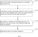
FIG. 2 is a flowchart of an image acquisition method according to an embodiment of the present disclosure; -
FIG. 3 is a flowchart of an image acquisition method according to another embodiment of the present disclosure; and -
FIG. 4 is a block diagram of an image acquisition terminal according to an embodiment of the present disclosure. - In order to illustrate the embodiments or existing technical solutions more clearly, a brief description of drawings that assists the description of embodiments of present disclosure or existing art will be provided below. It should be noted that, in the case of no conflict, the embodiments of the present disclosure and the features of each embodiment can be combined mutually. The invention will now be described in detail on the basis of preferred embodiments and drawings. It is to be understood that various changes may be made without departing from the spirit and scope of the disclosure and the embodiments of the present disclosure and features in the embodiments can be combined with each other.
- Referring to
FIG. 1, FIG. 1 is a block diagram of animage acquisition device 100 according to an embodiment of the present disclosure. Theimage acquisition device 100 in this embodiment can be applied to a mobile phone, a table computer, and other intelligent devices. The shooting referred in the present disclosure includes, but not limited to, taking pictures, recording video, and so on. Taking pictures is taken here as an example to describe the present disclosure. It should be understood that a video can be obtained by multiple pictures according to time order, namely, the present disclosure also applies to video shooting. - The
image acquisition device 100 includes acamera shooting module 110, acontrol module 120, aprocessing module 130 and adisplay module 140. - The
camera shooting module 110 can be a camera shooting module in a mobile phone or other terminals, and it is configured for image sampling (e.g., taking pictures, recording videos) for an external scenario. In this embodiment, thecamera shooting module 110 includes at least two cameras. - In this embodiment, the
camera shooting module 110 includes two cameras. Preferably, the two cameras have the same resolution. The two cameras are located adjacent to each other. Preferably, in the process of production, the distance of the two cameras should be as short as possible if the condition allows, so that when the two cameras shoot the same scenario, the images shot by the two cameras can be matched as many as possible. - The
control module 120 is configured to control thecamera shooting module 110 to shoot the scenario. In detail, thecontrol module 120 determines whether a shooting environment is a dark light environment or not, and controls thecamera shooting module 110 to shoot. In detail, when the shooting environment is a dark light environment, thecontrol module 120 controls the two cameras of thecamera shooting module 110 to shoot the same scenario simultaneously, otherwise, thecontrol module 120 controls one of the two cameras of thecamera shooting module 110 to shoot. Thecontrol module 120 is also configured to, according to a continuous shooting instruction of a user, control the two cameras to continuously shoot the same scenario simultaneously in the dark light environment, namely, thecontrol module 120 is configured to control each of the two cameras to conduct multiple shootings. In the process of multiple shootings, thecontrol module 120 can control the two cameras to shoot simultaneously for each shooting. - In detail, the
control module 120 can include a darklight judgment unit 121 and acontrol unit 122. The darklight judgment unit 121 is configured to detect the environment illumination while shooting. When the environment illumination is smaller than a preset threshold value, the darklight judgment unit 121 determines the shooting environment is a dark light environment. When the environment illumination is greater than the preset threshold value, thedark judgment unit 121 determines the shooting environment is a normal environment. Thecontrol unit 122 is configured to start a dark light shooting mode when the darklight judgment unit 121 determines the shooting environment is the dark light environment, namely, thecontrol unit 122 controls the two cameras to shoot the same scenario simultaneously. When the darklight judgment unit 121 determines the shooting environment is the normal environment, thecontrol unit 122 starts a normal shooting mode, namely, thecontrol unit 122 controls one camera of the two cameras of thecamera shooting module 110 to shoot. - The
processing module 130 is configured to process images shot by thecamera shooting module 110 for the same scenario, so as to obtain an image with enhanced brightness. - In detail, the
processing module 130 can include acorrection unit 131, adenoising unit 132 and abrightness superposition unit 133. - There is a distance between the two cameras of the
camera shooting module 110, so the images shot simultaneously by the two cameras for the same scenario may have deviation. Thecorrection unit 131 is configured to correct the images shot simultaneously by the two cameras for the same scenario according to a distance between the two cameras and a location relationship of the two cameras, so as to make two images coincide. Namely, after correction, the same shooting object is located at the same location in the two images shot by the two cameras, that is, the location of a shooting object in the image shot by one camera of the two cameras is the same as the location of the shooting object in the image shot by another camera of the two cameras. - In detail, in this embodiment, the
correction unit 131 corrects images employing the following method: firstly, determining three points A, B and C on the surface which is H1 away from both the two cameras and is perpendicular to the optical axis, and obtaining images shot simultaneously by the two cameras; determining the corresponding imaging points are A0, B0 and C0 respectively in the image shot by one camera of the two cameras; and determining the corresponding imaging points are A1, B1 and C1 respectively in the image shot by another camera of the two cameras. Supposing that the coordinates of pixel points corresponding to A0, B0 and C0 are (Xa0, Ya0), (Xb0, Yb0) and (Xc0, Yc0) respectively, and the coordinates of pixel points corresponding to A1, B1 and C1 are (Xa1, Ya1), (Xb1, Yb1) and (Xc1, Yc1) respectively, there exists the following relations:


- After imaging, the coordinates (namely, the location of the points in the image) of the above six pixel points are known, so the values of correction parameters m, n, k1, k2, k3 and k4 can be calculated.
- According to the above mentioned method, the correction parameters of different surfaces where the distances between each surface and the cameras are different can be calculated. And the correction parameters corresponding to different surfaces where the distances between each surface and the cameras are different can be stored so as to obtain a corresponding relationship between the correction parameters and the surfaces. Therefore, when the two cameras are employed to shoot simultaneously, the
image acquisition device 100 can obtain the pixel point in the image shot by another camera of the two cameras corresponding to a pixel point in the image shot by one camera of the two cameras. By moving one image of the two images shot by the two cameras, the pixel points of the two images can completely correspond, so as to achieve to correct the two images. - The
denoising unit 132 is configured to remove noises in two corrected images shot simultaneously by the two cameras. Thedenoising unit 132 can adopt a denoising method to remove the noise. In this embodiment, thedenoising unit 132 adopts the following method to remove the noise: firstly, obtaining the brightness value of each pixel point in the two corrected images shot simultaneously by the two cameras; and setting the corresponding pixel points in the two images shot simultaneously by the two cameras, where the difference of whose brightness value or color value is greater than a preset threshold value, to be the noises; finally, removing the noises in the two images respectively, and generating the brightness and the color of the pixel points located at the noises according to brightness information and the color value of the pixel points around the noises. - The
brightness superposition unit 133 is configured to superpose the brightness of corresponding pixel points in the two images shot simultaneously by the two cameras, so as to obtain an image with enhanced brightness. - Understandably, when the two cameras are controlled to conduct multiple continuous shootings, the
correction unit 131 corrects the two images shot simultaneously by the two cameras for each shooting. Thedenoising unit 132 is configured to remove the noises in the two corrected images shot simultaneously by the two cameras for each shooting. Thebrightness superposition unit 133 is configured to superpose the brightness of the pixel points in the two images shot currently by the two cameras with the brightness of corresponding pixel points in the image with enhanced brightness obtained by superposing the two images shot by the two cameras last time, so as to obtain an image with enhanced brightness. Namely, after a first shooting, thebrightness superposition unit 133 superposes the brightness of corresponding pixel points in the images shot by the two cameras for the first time only, thereby obtaining an image with enhanced brightness after the first shooting. After a second shooting, thebrightness superposition unit 133 superposes the brightness of the pixel points in the images shot by the two cameras for the second time with the brightness of corresponding pixel points in the image with enhanced brightness obtained after the first shooting, so as to obtain an image with enhanced brightness after the second shooting. In this way, with the increasing number of continuous shootings, the image brightness of final obtained image is significantly enhanced. Thedisplay module 140 is configured to display the image with enhanced brightness processed by theprocessing module 130. Understandably, when the two cameras conduct multiple continuous shootings, thedisplay module 140 is configured to display the image with enhanced brightness obtained after each shooting, so that a photographer can directly observe the image with enhanced brightness obtained after multiple shootings and processing. When the brightness of an image observed currently by the photographer meets the requirement, thecontrol module 120 can control the two cameras to stop continuous shootings. Understandably, in the case of a normal shooting mode, thedisplay module 140 is further configured to display the images shot by one camera of the two cameras of thecamera shooting module 110. - The
image acquisition device 100 provided in the technical solution includes two cameras. When the shooting environment is a dark light environment, thecontrol module 120 can control the two cameras to shoot the same scenario simultaneously to obtain two images; and theprocessing module 130 can process the two images, so as to obtain an image with enhanced brightness. Therefore, theimage acquisition device 100 provided in the technical solution can obtain an image with enhanced brightness in a dark light environment. The two cameras provided in the technical solution can be controlled to shoot the same scenario simultaneously, which can solve the problem of obtained images to be blurring due to increasing exposure time in the existing technology. - The present disclosure also provides an image acquisition method, and the image acquisition method can be realized by the
image acquisition device 100 provided by the embodiment of the technical solution as shown inFIG. 1 . The image acquisition method includes the following steps. - Step S101, determining whether a shooting environment is a dark light environment or not.
- In this step, the dark
light judgment unit 121 can detect the environment illumination while shooting. When the environment illumination is smaller than a preset threshold value, the darklight judgment unit 121 determines the shooting environment is a dark light environment. When the environment illumination is greater than the preset threshold value, thedark judgment unit 121 determines the shooting environment is a normal environment. - Step S102, controlling two cameras of the image acquisition device to shoot the same scenario simultaneously to obtain two images when the shooting environment is the dark light environment.
- When the dark
light judgment unit 121 determines the shooting environment is the dark light environment, thecontrol unit 122 starts a dark light shooting mode, namely, thecontrol unit 122 controls the two cameras to shoot the same scenario simultaneously. When the darklight judgment unit 121 determines the shooting environment is the normal environment, thecontrol unit 122 starts a normal shooting mode, namely, thecontrol unit 122 controls one camera of the two cameras to shoot, and the shooting could be stopped after obtaining the shot images. - Step S103, processing the two images shot simultaneously by the two cameras for the same scenario, so as to obtain an image with enhanced brightness.
- In detail, the step S103 can include the following steps:
- Firstly, the
correction unit 131 corrects the two images shot simultaneously by the two cameras for the same scenario. There is a distance between the two cameras of thecamera shooting module 110, so the images shot simultaneously by the two cameras for the same scenario may have deviation. According to a distance between the two cameras and a location relationship of the two cameras, thecorrection unit 131 corrects the images shot simultaneously by the two cameras for the same scenario, so as to make two images coincide. Namely, after correction, the same shooting object is located at the same location in the two images. - Then, the
denoising unit 132 removes noises in two corrected images shot simultaneously by the two cameras. - The
denoising unit 132 can adopt a denoising method to remove the noise. In this embodiment, thedenoising unit 132 adopts the following method to remove the noise: firstly, obtaining the brightness value of each pixel point in the two corrected images shot simultaneously by the two cameras; and setting the corresponding pixel points in the two images shot simultaneously by the two cameras, where the difference of whose brightness value or color value is greater than a preset threshold value, to be the noises; finally, removing the noises in the two images respectively, and generating the brightness and the color of the pixel points located at the noises according to brightness information and the color value of the pixel points around the noises. - Finally, after removing the noises of the images, the
brightness superposition unit 133 superposes the brightness of corresponding pixel points in the two images shot simultaneously by the two cameras, so as to obtain an image with enhanced brightness. Namely, thebrightness superposition unit 133 superposes the brightness value of the corresponding pixel points in the two images to obtain the brightness value of the pixel points in an image with enhanced brightness, so the brightness value of the pixel points in the image with enhanced brightness is approximately equal to the double of the brightness value of each original image of the two images shot by the two cameras. - Step S104, displaying the image with enhanced brightness.
- After the step S104, the image acquisition method can also include a step of storing the image with enhanced brightness.
- Understandably, when a photographer can confirm that the shooting environment is a dark light environment or the shooting environment defaults to be a dark light environment, the image acquisition method provided by this embodiment can not include the step of determining whether a shooting environment is a dark light environment or not.
- Understandably, in this embodiment, the
camera shooting module 110 including two cameras is taken here as an example. When employing more than two cameras, theimage acquisition device 100 can also control the more than two cameras to shoot simultaneously, and process the images shot by the more than two cameras, so as to obtain an image with enhanced brightness. - The
image acquisition device 100 provided in the technical solution includes two cameras. When the shooting environment is a dark light environment, thecontrol module 120 can control the two cameras to shoot the same scenario simultaneously to obtain two images; and theprocessing module 130 can process the two images, so as to obtain an image with enhanced brightness. Therefore, theimage acquisition device 100 provided in the technical solution can obtain an image with enhanced brightness in a dark light environment. The two cameras provided in the technical solution can be controlled to shoot the same scenario simultaneously, which can solve the problem of obtained images to be blurring due to increasing exposure time in the existing technology. - Another embodiment of the technical solution also provides an image acquisition method, and the image acquisition method can be realized by the
image acquisition device 100 provided by the embodiment of the technical solution as shown inFIG. 1 . The image acquisition method includes the following steps. - Step S201, determining whether a shooting environment is a dark light environment or not.
- In this step, the dark
light judgment unit 121 can detect the environment illumination while shooting. When the environment illumination is smaller than a preset threshold value, the darklight judgment unit 121 determines the shooting environment is a dark light environment. When the environment illumination is greater than the preset threshold value, thedark judgment unit 121 determines the shooting environment is a normal environment. - Step S202, controlling two cameras of the image acquisition device to shoot the same scenario simultaneously to obtain two images when the shooting environment is the dark light environment.
- When the dark
light judgment unit 121 determines the shooting environment is the dark light environment, thecontrol unit 122 starts a dark light shooting mode, namely, thecontrol unit 122 controls the two cameras to shoot the same scenario simultaneously. When the darklight judgment unit 121 determines the shooting environment is the normal environment, thecontrol unit 122 starts a normal shooting mode, namely, thecontrol unit 122 controls one camera of the two cameras to shoot, and the shooting could be stopped after obtaining the shot images. - Step S203, processing the two images shot simultaneously by the two cameras for the same scenario, so as to obtain an image with enhanced brightness.
- In detail, the step S203 can include the following steps:
- Firstly, the
correction unit 131 corrects the two images shot simultaneously by the two cameras for the same scenario. There is a distance between the two cameras of thecamera shooting module 110, so the images shot simultaneously by the two cameras for the same scenario may have deviation. According to a distance between the two cameras and a location relationship of the two cameras, thecorrection unit 131 corrects the images shot simultaneously by the two cameras for the same scenario, so as to make two images coincide. Namely, after correction, the same shooting object is located at the same location in the two images. - Then, the
denoising unit 132 removes noises in two corrected images shot simultaneously by the two cameras. - The
denoising unit 132 can adopt a denoising method to remove the noise. In this embodiment, thedenoising unit 132 adopts the following method to remove the noise: firstly, obtaining the brightness value of each pixel point in the two corrected images shot simultaneously by the two cameras; and setting the corresponding pixel points in the two images shot simultaneously by the two cameras, where the difference of whose brightness value or color value is greater than a preset threshold value, to be the noises; finally, removing the noises in the two images respectively, and generating the brightness and the color of the pixel points located at the noises according to brightness information and the color value of the pixel points around the noises. - Finally, after removing the noises of the images, the
brightness superposition unit 133 superposes the brightness of corresponding pixel points in the two images shot simultaneously by the two cameras, so as to obtain an image with enhanced brightness. Namely, thebrightness superposition unit 133 superposes the brightness value of the corresponding pixel points in the two images to obtain the brightness value of the pixel points in an image with enhanced brightness, so the brightness value of the pixel points in the image with enhanced brightness is approximately equal to the double of the brightness value of each original image of the two images shot by the two cameras. - The step S203 can also include a step of displaying the image with enhanced brightness after the first shooting.
- Step S204, determining whether a continuous shooting instruction is received or not, and conducting a continuous shooting to obtain multi-frame images if the continuous shooting instruction is received, and processing the multi-frame images to obtain an image with enhanced brightness, and displaying the image with enhanced brightness.
- In the process of the continuous shooting, the
image acquisition device 100 processes two images shot by the two cameras every time, and superposes the two images with the image with enhanced brightness obtained last time, so as to obtain an image with enhanced brightness after each shooting. Furthermore, theimage acquisition device 100 displays each image with enhanced brightness obtained after each shooting. When the continuous shooting stops, a final image with enhanced brightness can be obtained after multiple continuous shootings. - When the brightness of the image with enhanced brightness obtained after the first shooting still cannot meet the requirement, a user can take pressing a shooting button continuously as a continuous shooting instruction, and take stopping pressing the shooting button as a continuous shooting stop instruction. In detail, in the process of the continuous shooting, the
image acquisition device 100 can employ the following method to obtain an image with enhanced brightness to meet the requirement. - Firstly, the
control unit 122 controls the two cameras to shoot the same scenario simultaneously for the second time to obtain two images; then, thecorrection unit 131 corrects the two images shot for the second time and thedenoising unit 132 removes noises in two corrected images; next, thebrightness superposition unit 133 superposes the brightness of the pixel points in the two images shot for the second time with the brightness of the pixel points in the image with enhanced brightness obtained after the first shooting, so as to obtain an image with enhanced brightness after the second shooting, and thedisplay module 140 displays the image with enhanced brightness; finally, theimage acquisition device 100 performs multiple shootings and image synthesis in the same way as the second shooting, and until theimage acquisition device 100 receives a continuous shooting stop instruction, the shooting stops and a final image with enhanced brightness can be obtained after multiple shootings. - If the continuous shooting instruction is not received after obtaining the image with enhanced brightness for the first shooting, the shooting stops.
- Understandably, in this embodiment, the
camera shooting module 110 including two cameras is taken here as an example. When employing more than two cameras, theimage acquisition device 100 can also control the more than two cameras to shoot simultaneously, and process the images shot by the more than two cameras, so as to obtain an image with enhanced brightness. - The image acquisition method provided in the technical solution includes two cameras. When the shooting environment is a dark light environment, the
control module 120 can control the two cameras to shoot the same scenario simultaneously to obtain two images; and theprocessing module 130 can process the two images, so as to obtain an image with enhanced brightness. Therefore, the image acquisition method provided in the technical solution can obtain an image with enhanced brightness in a dark light environment. The two cameras provided in the technical solution can be controlled to shoot the same scenario simultaneously, which can solve the problem of obtained images to be blurring due to increasing exposure time in the existing technology. - Furthermore, in the process of the continuous shooting, the
image acquisition device 100 displays each image with enhanced brightness after each shooting, and the photographer can determine whether to stop the continuous shooting or not on the basis whether displayed images meet the requirement or not. Therefore, by means of the image acquisition method provided by the technical solution, the user can determine whether to stop the continuous shooting or not based on observing the image with enhanced brightness obtained in the process of shooting, thus it is controllable for the obtained shot images, which provides a better user experience. - The present disclosure also provides an
image acquisition terminal 4, and theimage acquisition terminal 4 can be a mobile phone, a table computer, or other electronic devices. Referring toFIG. 4 , theimage acquisition terminal 4 can include: at least oneprocessor 41, such as a CPU (central processing unit), at least onecommunication bus 42, amemory 43 and acamera shooting module 44. Thecommunication bus 42 is configured to realize the connections and communications of the at least oneprocessor 41, thememory 43 and thecamera shooting module 44; thecamera shooting module 44 includes at least two cameras; thememory 43 can be a high speed RAM memory, or a non-volatile memory, such as at least one disk memory. Thememory 43 stores a group of program codes, and theprocessor 41 is configured to call the program code stored in thememory 43 to execute for: - controlling at least two cameras to shoot the same scenario to obtain at least two images; and
- processing the at least two images shot by the at least two cameras for the same scenario, so as to obtain an image with enhanced brightness.
- Wherein, in detail, the
processor 41 calling the program codes stored in thememory 43 to execute for processing the at least two images shot by the at least two cameras for the same scenario, so as to obtain an image with enhanced brightness, can include: - correcting the at least two images shot simultaneously by the two cameras for the same scenario according to a distance between the at least two cameras and a location relationship of the at least two cameras; and
- superposing the brightness of corresponding pixel points in the at least two images shot simultaneously by the at least two cameras, so as to obtain an image with enhanced brightness.
- Wherein, in detail, the
processor 41 calling the program codes stored in thememory 43 to execute for controlling at least two cameras to shoot the same scenario to obtain at least two images, can include: - determining whether a shooting environment is a dark light environment or not; and controlling the at least two cameras to shoot the same scenario to obtain at least two images if the shooting environment is the dark light environment.
- Wherein, the
processor 41 calls the program codes stored in thememory 43 to further executes for: - controlling the at least two cameras to continuously shoot the same scenario simultaneously to obtain at least two images on the basis that a continuous shooting instruction is received.
- Wherein, in detail, the
processor 41 calling the program codes stored in thememory 43 to execute for processing the at least two images shot by the at least two cameras for the same scenario, so as to obtain an image with enhanced brightness, can include: - correcting the at least two images shot simultaneously by the at least two cameras every time;
- removing noises in at least two corrected images shot simultaneously by the at least two cameras every time;
- superposing the brightness of the pixel points in images shot currently by the at least two cameras with the brightness of corresponding pixel points in the image with enhanced brightness obtained by superposing at least two images shot by the at least two cameras last time, so as to obtain an image with enhanced brightness after multiple shootings.
- Wherein, after the step of processing the at least two images shot by the at least two cameras for the same scenario, so as to obtain an image with enhanced brightness, the processor calls the program codes stored in the memory to further executes for:
- displaying the image with brightness enhanced obtained after each shooting.
- While the present invention has been described with reference to particular embodiments, it will be understood that the embodiments are illustrative and that the invention scope is not so limited. Alternative embodiments of the present invention will become apparent to those having ordinary skill in the art to which the present invention pertains. Such alternate embodiments are considered to be encompassed within the spirit and scope of the present invention.
Claims (15)
- An image acquisition device, comprising a camera shooting module, a control module and a processing module, wherein,the camera shooting module comprises at least two cameras;the control module is configured to control the at least two cameras of the camera shooting module to shoot the same scenario to obtain at least two images; andthe processing module is configured to process the at least two images shot by the at least two cameras of the camera shooting module for the same scenario, so as to obtain an image with enhanced brightness.
- The image acquisition device according to claim 1, the processing module comprising a correction unit and a brightness superposition unit; wherein, the correction unit is configured to correct the at least two images shot simultaneously by the at least two cameras for the same scenario according to a distance between the at least two cameras and a location relationship of the at least two cameras; and the brightness superposition unit is configured to superpose the brightness of corresponding pixel points in the at least two images shot simultaneously by the at least two cameras, so as to obtain an image with enhanced brightness.
- The image acquisition device according to claim 1, the control module comprising a dark light judgment unit and a control unit; wherein, the dark light judgment unit is configured to detect the environment illumination while shooting, and determine the shooting environment is a dark light environment when the environment illumination is smaller than a preset threshold value; and the control unit is configured to control the at least two cameras to shoot the same scenario simultaneously on the basis that the dark light judgment unit determines the shooting environment is the dark light environment.
- The image acquisition device according to claim 3, wherein, the control unit is further configured to control the at least two cameras to continuously shoot the same scenario simultaneously to obtain at least two images on the basis that a continuous shooting instruction is received.
- The image acquisition device according to claim 4, the processing module comprising a correction unit, a denoising unit and a brightness superposition unit; wherein, the correction unit is configured to correct the at least two images shot simultaneously by the at least two cameras every time; the denoising unit is configured to remove noises in at least two corrected images shot simultaneously by the at least two cameras every time; and the brightness superposition unit is configured to superpose the brightness of the pixel points in at least two images shot currently by the at least two cameras with the brightness of corresponding pixel points in the image with enhanced brightness obtained by superposing at least two images shot by the at least two cameras last time, so as to obtain an image with enhanced brightness after multiple shootings.
- The image acquisition device according to claim 5, the image acquisition device further comprising a display module; wherein, the display module is configured to display the image with enhanced brightness obtained after each shooting.
- An image acquisition method applied to an image acquisition device, comprising:controlling at least two cameras to shoot the same scenario to obtain at least two images; andprocessing the at least two images shot by the at least two cameras for the same scenario, so as to obtain an image with enhanced brightness.
- The image acquisition method according to claim 7, further comprising: determining whether a shooting environment is a dark light environment or not; and controlling the at least two cameras to shoot the same scenario when the shooting environment is the dark light environment.
- An image acquisition method applied to an image acquisition device, comprising:controlling at least two cameras to shoot the same scenario to obtain at least two images for the first time;processing the at least two images shot by the at least two cameras for the same scenario, so as to obtain an image with enhanced brightness; anddetermining whether a continuous shooting instruction is received or not, and controlling the at least two cameras to shoot continuously to obtain multi-frame images if the continuous shooting instruction is received, and processing the multi-frame images to obtain an image with enhanced brightness, and displaying the image with enhanced brightness.
- An image acquisition terminal, comprising a processor, a memory and a camera shooting module, wherein, the camera shooting module comprises at least two cameras; the memory stores a group of program codes; the processor is configured to call the program codes stored in the memory to execute for:controlling at least two cameras to shoot the same scenario to obtain at least two images; andprocessing the at least two images shot by the at least two cameras for the same scenario, so as to obtain an image with enhanced brightness.
- The image acquisition terminal according to claim 10, wherein, the processor calling the program codes stored in the memory to execute for processing the at least two images shot by the at least two cameras for the same scenario, so as to obtain an image with enhanced brightness, comprises:correcting the at least two images shot simultaneously by the two cameras for the same scenario according to a distance between the at least two cameras and a location relationship of the at least two cameras; andsuperposing the brightness of corresponding pixel points in the at least two images shot simultaneously by the at least two cameras, so as to obtain an image with enhanced brightness.
- The image acquisition terminal according to claim 10, wherein, the processor calling the program codes stored in the memory to execute for controlling at least two cameras to shoot the same scenario to obtain at least two images, comprises:determining whether a shooting environment is a dark light environment or not; and controlling the at least two cameras to shoot the same scenario to obtain at least two images if the shooting environment is the dark light environment.
- The image acquisition terminal according to claim 12, wherein, the processor calls the program codes stored in the memory to further executes for:controlling the at least two cameras to continuously shoot the same scenario simultaneously to obtain at least two images on the basis that a continuous shooting instruction is received.
- The image acquisition terminal according to claim 13, wherein, the processor calling the program codes stored in the memory to execute for processing the at least two images shot by the at least two cameras for the same scenario, so as to obtain an image with enhanced brightness, comprises:correcting the at least two images shot simultaneously by the at least two cameras;removing noises in at least two corrected images shot simultaneously by the at least two cameras; andsuperposing the brightness of the pixel points in images shot currently by the at least two cameras with the brightness of corresponding pixel points in the image with enhanced brightness obtained by superposing at least two images shot by the at least two cameras last time, so as to obtain an image with enhanced brightness after multiple shootings.
- The image acquisition terminal according to claim 14, wherein, after the step of processing the at least two images shot by the at least two cameras for the same scenario, so as to obtain an image with enhanced brightness, the processor calls the program codes stored in the memory to further executes for:displaying the image with enhanced brightness obtained after each shooting.
Applications Claiming Priority (2)
| Application Number | Priority Date | Filing Date | Title |
|---|---|---|---|
| CN201410234555.2A CN103986874A (en) | 2014-05-29 | 2014-05-29 | An image acquisition device, image acquisition method and terminal |
| PCT/CN2015/080281 WO2015180686A1 (en) | 2014-05-29 | 2015-05-29 | Image acquisition device, image acquisition method and terminal |
Publications (3)
| Publication Number | Publication Date |
|---|---|
| EP3151539A1 true EP3151539A1 (en) | 2017-04-05 |
| EP3151539A4 EP3151539A4 (en) | 2018-01-24 |
| EP3151539B1 EP3151539B1 (en) | 2019-07-24 |
Family
ID=51278688
Family Applications (1)
| Application Number | Title | Priority Date | Filing Date |
|---|---|---|---|
| EP15800509.0A Active EP3151539B1 (en) | 2014-05-29 | 2015-05-29 | Image acquisition device, image acquisition method and terminal |
Country Status (4)
| Country | Link |
|---|---|
| US (1) | US10063789B2 (en) |
| EP (1) | EP3151539B1 (en) |
| CN (1) | CN103986874A (en) |
| WO (1) | WO2015180686A1 (en) |
Cited By (1)
| Publication number | Priority date | Publication date | Assignee | Title |
|---|---|---|---|---|
| EP4508871A1 (en) | 2022-05-12 | 2025-02-19 | Samsung Electronics Co., Ltd. | Methods and systems for enhancing low light frame in a multi camera system |
Families Citing this family (37)
| Publication number | Priority date | Publication date | Assignee | Title |
|---|---|---|---|---|
| CN103986874A (en) | 2014-05-29 | 2014-08-13 | 宇龙计算机通信科技(深圳)有限公司 | An image acquisition device, image acquisition method and terminal |
| CN104284130A (en) * | 2014-10-29 | 2015-01-14 | 四川智诚天逸科技有限公司 | Video communication device |
| US12401911B2 (en) | 2014-11-07 | 2025-08-26 | Duelight Llc | Systems and methods for generating a high-dynamic range (HDR) pixel stream |
| US12401912B2 (en) | 2014-11-17 | 2025-08-26 | Duelight Llc | System and method for generating a digital image |
| CN104363375B (en) * | 2014-11-28 | 2018-03-27 | 广东欧珀移动通信有限公司 | A kind of method, apparatus and terminal of photo noise reduction |
| US12445736B2 (en) | 2015-05-01 | 2025-10-14 | Duelight Llc | Systems and methods for generating a digital image |
| CN104869309A (en) * | 2015-05-15 | 2015-08-26 | 广东欧珀移动通信有限公司 | Method and device for taking pictures |
| CN104883511A (en) * | 2015-06-12 | 2015-09-02 | 联想(北京)有限公司 | Image processing method and electronic equipment |
| CN105554483B (en) * | 2015-07-16 | 2018-05-15 | 宇龙计算机通信科技(深圳)有限公司 | A kind of image processing method and terminal |
| CN105657286A (en) * | 2015-07-29 | 2016-06-08 | 宇龙计算机通信科技(深圳)有限公司 | Photographing method and device based on double cameras |
| CN105141835A (en) * | 2015-08-04 | 2015-12-09 | 上海霆善信息科技有限公司 | Image acquisition system based on card swiping triggering |
| CN106878604B (en) * | 2015-12-10 | 2021-06-18 | 北京奇虎科技有限公司 | A method and electronic device for image generation based on electronic device |
| CN106878605B (en) * | 2015-12-10 | 2021-01-29 | 北京奇虎科技有限公司 | Image generation method based on electronic equipment and electronic equipment |
| CN105635568B (en) * | 2015-12-25 | 2019-09-17 | 青岛海信移动通信技术股份有限公司 | Image processing method and mobile terminal in a kind of mobile terminal |
| CN107230187B (en) * | 2016-03-25 | 2022-05-24 | 北京三星通信技术研究有限公司 | Method and device for processing multimedia information |
| CN105812677B (en) * | 2016-04-29 | 2019-07-30 | 宇龙计算机通信科技(深圳)有限公司 | An image generation method and system |
| CN107438165A (en) * | 2016-05-25 | 2017-12-05 | 鸿富锦精密电子(郑州)有限公司 | Electronic installation and self-timer householder method with self-timer miscellaneous function |
| CN106161933B (en) * | 2016-06-30 | 2019-05-17 | 维沃移动通信有限公司 | An image processing method and mobile terminal |
| CN106060404A (en) * | 2016-07-15 | 2016-10-26 | 深圳市金立通信设备有限公司 | Photographing mode selection method and terminal |
| CN106210584A (en) * | 2016-08-02 | 2016-12-07 | 乐视控股(北京)有限公司 | A kind of video recording method and device |
| CN106572246B (en) * | 2016-10-31 | 2020-11-17 | 太仓市昊博技术服务有限公司 | Camera opening device, terminal and camera opening method |
| CN106506963A (en) * | 2016-11-30 | 2017-03-15 | 努比亚技术有限公司 | A kind of photographic method and terminal based on dual camera |
| US10965878B2 (en) * | 2016-12-15 | 2021-03-30 | Koito Manufacturing Co., Ltd. | Vehicle illumination system and vehicle |
| CN110536647B (en) * | 2017-02-10 | 2023-03-28 | 柯惠有限合伙公司 | Systems, methods, and computer-readable media for processing and compositing ultrasound images in the presence of motion |
| CN107087112B (en) | 2017-05-31 | 2020-01-10 | Oppo广东移动通信有限公司 | Control method and control device for double cameras |
| CN109391751B (en) * | 2017-08-11 | 2020-12-08 | 深圳富泰宏精密工业有限公司 | Electronic device and camera control method |
| CN107948511B (en) * | 2017-11-28 | 2019-10-25 | Oppo广东移动通信有限公司 | Image brightness processing method, device, storage medium and image brightness processing device |
| CN109951629A (en) * | 2017-12-21 | 2019-06-28 | 姜鹏飞 | A kind of method and device for noise reduction |
| CN111314603B (en) | 2018-03-27 | 2021-11-19 | 华为技术有限公司 | Photographing method, photographing device and mobile terminal |
| US10742892B1 (en) | 2019-02-18 | 2020-08-11 | Samsung Electronics Co., Ltd. | Apparatus and method for capturing and blending multiple images for high-quality flash photography using mobile electronic device |
| US11062436B2 (en) | 2019-05-10 | 2021-07-13 | Samsung Electronics Co., Ltd. | Techniques for combining image frames captured using different exposure settings into blended images |
| US11095829B2 (en) | 2019-06-11 | 2021-08-17 | Samsung Electronics Co., Ltd. | Apparatus and method for high dynamic range (HDR) image creation of dynamic scenes using graph cut-based labeling |
| CN110769151B (en) | 2019-09-27 | 2021-10-15 | 维沃移动通信有限公司 | Image processing method, apparatus, electronic device and medium |
| CN110661972B (en) * | 2019-09-27 | 2021-02-23 | 维沃移动通信有限公司 | Image processing method, image processing apparatus, electronic device, and medium |
| CN110732426A (en) * | 2019-10-24 | 2020-01-31 | 张柯 | Water mist jet power regulating system |
| US10911691B1 (en) | 2019-11-19 | 2021-02-02 | Samsung Electronics Co., Ltd. | System and method for dynamic selection of reference image frame |
| US11430094B2 (en) | 2020-07-20 | 2022-08-30 | Samsung Electronics Co., Ltd. | Guided multi-exposure image fusion |
Family Cites Families (18)
| Publication number | Priority date | Publication date | Assignee | Title |
|---|---|---|---|---|
| CN1035467A (en) | 1988-03-04 | 1989-09-13 | 蔡军荣 | Double-windscreen sedan |
| US8698924B2 (en) * | 2007-03-05 | 2014-04-15 | DigitalOptics Corporation Europe Limited | Tone mapping for low-light video frame enhancement |
| US7463296B2 (en) * | 2004-04-01 | 2008-12-09 | Microsoft Corporation | Digital cameras with luminance correction |
| US7292257B2 (en) * | 2004-06-28 | 2007-11-06 | Microsoft Corporation | Interactive viewpoint video system and process |
| WO2006079963A2 (en) * | 2005-01-28 | 2006-08-03 | Koninklijke Philips Electronics N.V. | Device for registering images |
| JP4706466B2 (en) * | 2005-12-16 | 2011-06-22 | 株式会社日立製作所 | Imaging device |
| US8456515B2 (en) * | 2006-07-25 | 2013-06-04 | Qualcomm Incorporated | Stereo image and video directional mapping of offset |
| CN200944633Y (en) * | 2006-08-15 | 2007-09-05 | 沈洪 | Multi-scene imaging apparatus |
| JP2009017078A (en) * | 2007-07-03 | 2009-01-22 | Fujifilm Corp | Digital still camera and operation control method thereof |
| CN101631202A (en) * | 2008-07-16 | 2010-01-20 | 肖长诗 | Method for acquiring images with super-wide dynamic range |
| CN101510007B (en) * | 2009-03-20 | 2011-01-05 | 北京科技大学 | Real time shooting and self-adapting fusing device for infrared light image and visible light image |
| US9073138B2 (en) * | 2011-05-16 | 2015-07-07 | Lincoln Global, Inc. | Dual-spectrum digital imaging welding helmet |
| CN103546730A (en) * | 2012-07-11 | 2014-01-29 | 北京博雅华录视听技术研究院有限公司 | Method for enhancing light sensitivities of images on basis of multiple cameras |
| CN103780840B (en) * | 2014-01-21 | 2016-06-08 | 上海果壳电子有限公司 | Two camera shooting image forming apparatus of a kind of high-quality imaging and method thereof |
| EP3129954A4 (en) * | 2014-04-07 | 2017-10-18 | BAE SYSTEMS Information and Electronic Systems Integration Inc. | Contrast based image fusion |
| CN103986874A (en) * | 2014-05-29 | 2014-08-13 | 宇龙计算机通信科技(深圳)有限公司 | An image acquisition device, image acquisition method and terminal |
| KR102195311B1 (en) * | 2014-09-15 | 2020-12-24 | 삼성전자주식회사 | Method for enhancing noise characteristics of image and an electronic device thereof |
| US9716876B2 (en) * | 2015-04-01 | 2017-07-25 | Sony Corporation | Power efficient multiple camera system |
-
2014
- 2014-05-29 CN CN201410234555.2A patent/CN103986874A/en active Pending
-
2015
- 2015-05-29 US US15/314,456 patent/US10063789B2/en active Active
- 2015-05-29 WO PCT/CN2015/080281 patent/WO2015180686A1/en not_active Ceased
- 2015-05-29 EP EP15800509.0A patent/EP3151539B1/en active Active
Cited By (2)
| Publication number | Priority date | Publication date | Assignee | Title |
|---|---|---|---|---|
| EP4508871A1 (en) | 2022-05-12 | 2025-02-19 | Samsung Electronics Co., Ltd. | Methods and systems for enhancing low light frame in a multi camera system |
| EP4508871A4 (en) * | 2022-05-12 | 2025-08-13 | Samsung Electronics Co Ltd | Methods and systems for improving a low-light frame in a multi-camera system |
Also Published As
| Publication number | Publication date |
|---|---|
| EP3151539B1 (en) | 2019-07-24 |
| WO2015180686A1 (en) | 2015-12-03 |
| CN103986874A (en) | 2014-08-13 |
| US20170201692A1 (en) | 2017-07-13 |
| US10063789B2 (en) | 2018-08-28 |
| EP3151539A4 (en) | 2018-01-24 |
Similar Documents
| Publication | Publication Date | Title |
|---|---|---|
| EP3151539B1 (en) | Image acquisition device, image acquisition method and terminal | |
| EP3358819B1 (en) | Photographing method, photographing device and terminal | |
| CN105578042B (en) | A kind of transmission method and terminal of image data | |
| CN106851122B (en) | Calibration method and device for automatic exposure parameters based on double-camera system | |
| US9819874B2 (en) | Camera color temperature compensation system and smart terminal employing same | |
| EP2169963A1 (en) | Image pickup device and image pickup method | |
| CN108307098B (en) | Fisheye camera shadow correction parameter determination method, correction method and device and fisheye camera | |
| CN109697698B (en) | Low illuminance enhancement processing method, apparatus and computer readable storage medium | |
| CN112752023A (en) | Image adjusting method and device, electronic equipment and storage medium | |
| CN105120247B (en) | A kind of white balance adjustment method and electronic equipment | |
| US9532023B2 (en) | Color reproduction of display camera system | |
| CN108717691B (en) | Image fusion method and device, electronic equipment and medium | |
| CN105141841B (en) | Picture pick-up device and its method | |
| US20120113238A1 (en) | Drawn image sharing apparatus, drawn image sharing system, and drawn image sharing method | |
| CN103546730A (en) | Method for enhancing light sensitivities of images on basis of multiple cameras | |
| CN104183216A (en) | Method and device for controlling brightness of display screen of displayer | |
| US10750080B2 (en) | Information processing device, information processing method, and program | |
| CN104299188B (en) | Image correcting method and system | |
| EP4622243A3 (en) | Electronic device and method providing content associated with image to application | |
| KR101643612B1 (en) | Photographing method and apparatus and recording medium thereof | |
| US9800793B2 (en) | Method for generating target gain value of wide dynamic range operation | |
| CN114339173A (en) | Projection image correction method, laser projection system and readable storage medium | |
| CN108063933B (en) | Image processing method and device, computer readable storage medium and computer device | |
| US12225299B2 (en) | System and method for image banding detection | |
| EP4055814B1 (en) | A system for performing image motion compensation |
Legal Events
| Date | Code | Title | Description |
|---|---|---|---|
| STAA | Information on the status of an ep patent application or granted ep patent |
Free format text: STATUS: THE INTERNATIONAL PUBLICATION HAS BEEN MADE |
|
| PUAI | Public reference made under article 153(3) epc to a published international application that has entered the european phase |
Free format text: ORIGINAL CODE: 0009012 |
|
| STAA | Information on the status of an ep patent application or granted ep patent |
Free format text: STATUS: REQUEST FOR EXAMINATION WAS MADE |
|
| 17P | Request for examination filed |
Effective date: 20161125 |
|
| AK | Designated contracting states |
Kind code of ref document: A1 Designated state(s): AL AT BE BG CH CY CZ DE DK EE ES FI FR GB GR HR HU IE IS IT LI LT LU LV MC MK MT NL NO PL PT RO RS SE SI SK SM TR |
|
| AX | Request for extension of the european patent |
Extension state: BA ME |
|
| DAV | Request for validation of the european patent (deleted) | ||
| DAX | Request for extension of the european patent (deleted) | ||
| A4 | Supplementary search report drawn up and despatched |
Effective date: 20171221 |
|
| RIC1 | Information provided on ipc code assigned before grant |
Ipc: H04N 5/243 20060101ALI20171215BHEP Ipc: H04N 5/235 20060101ALI20171215BHEP Ipc: H04N 5/217 20110101ALI20171215BHEP Ipc: H04N 5/232 20060101AFI20171215BHEP Ipc: G06T 5/50 20060101ALN20171215BHEP Ipc: H04N 5/225 20060101ALI20171215BHEP |
|
| STAA | Information on the status of an ep patent application or granted ep patent |
Free format text: STATUS: EXAMINATION IS IN PROGRESS |
|
| 17Q | First examination report despatched |
Effective date: 20181002 |
|
| RIC1 | Information provided on ipc code assigned before grant |
Ipc: H04N 5/225 20060101ALI20190411BHEP Ipc: H04N 5/232 20060101AFI20190411BHEP Ipc: H04N 5/235 20060101ALI20190411BHEP Ipc: H04N 5/217 20110101ALI20190411BHEP Ipc: G06T 5/50 20060101ALN20190411BHEP Ipc: H04N 5/243 20060101ALI20190411BHEP |
|
| GRAP | Despatch of communication of intention to grant a patent |
Free format text: ORIGINAL CODE: EPIDOSNIGR1 |
|
| STAA | Information on the status of an ep patent application or granted ep patent |
Free format text: STATUS: GRANT OF PATENT IS INTENDED |
|
| GRAS | Grant fee paid |
Free format text: ORIGINAL CODE: EPIDOSNIGR3 |
|
| INTG | Intention to grant announced |
Effective date: 20190521 |
|
| GRAA | (expected) grant |
Free format text: ORIGINAL CODE: 0009210 |
|
| STAA | Information on the status of an ep patent application or granted ep patent |
Free format text: STATUS: THE PATENT HAS BEEN GRANTED |
|
| AK | Designated contracting states |
Kind code of ref document: B1 Designated state(s): AL AT BE BG CH CY CZ DE DK EE ES FI FR GB GR HR HU IE IS IT LI LT LU LV MC MK MT NL NO PL PT RO RS SE SI SK SM TR |
|
| REG | Reference to a national code |
Ref country code: GB Ref legal event code: FG4D |
|
| REG | Reference to a national code |
Ref country code: CH Ref legal event code: EP |
|
| REG | Reference to a national code |
Ref country code: DE Ref legal event code: R096 Ref document number: 602015034427 Country of ref document: DE |
|
| REG | Reference to a national code |
Ref country code: AT Ref legal event code: REF Ref document number: 1159672 Country of ref document: AT Kind code of ref document: T Effective date: 20190815 |
|
| REG | Reference to a national code |
Ref country code: IE Ref legal event code: FG4D |
|
| REG | Reference to a national code |
Ref country code: NL Ref legal event code: FP |
|
| REG | Reference to a national code |
Ref country code: LT Ref legal event code: MG4D |
|
| REG | Reference to a national code |
Ref country code: AT Ref legal event code: MK05 Ref document number: 1159672 Country of ref document: AT Kind code of ref document: T Effective date: 20190724 |
|
| PG25 | Lapsed in a contracting state [announced via postgrant information from national office to epo] |
Ref country code: NO Free format text: LAPSE BECAUSE OF FAILURE TO SUBMIT A TRANSLATION OF THE DESCRIPTION OR TO PAY THE FEE WITHIN THE PRESCRIBED TIME-LIMIT Effective date: 20191024 Ref country code: AT Free format text: LAPSE BECAUSE OF FAILURE TO SUBMIT A TRANSLATION OF THE DESCRIPTION OR TO PAY THE FEE WITHIN THE PRESCRIBED TIME-LIMIT Effective date: 20190724 Ref country code: PT Free format text: LAPSE BECAUSE OF FAILURE TO SUBMIT A TRANSLATION OF THE DESCRIPTION OR TO PAY THE FEE WITHIN THE PRESCRIBED TIME-LIMIT Effective date: 20191125 Ref country code: BG Free format text: LAPSE BECAUSE OF FAILURE TO SUBMIT A TRANSLATION OF THE DESCRIPTION OR TO PAY THE FEE WITHIN THE PRESCRIBED TIME-LIMIT Effective date: 20191024 Ref country code: LT Free format text: LAPSE BECAUSE OF FAILURE TO SUBMIT A TRANSLATION OF THE DESCRIPTION OR TO PAY THE FEE WITHIN THE PRESCRIBED TIME-LIMIT Effective date: 20190724 Ref country code: HR Free format text: LAPSE BECAUSE OF FAILURE TO SUBMIT A TRANSLATION OF THE DESCRIPTION OR TO PAY THE FEE WITHIN THE PRESCRIBED TIME-LIMIT Effective date: 20190724 Ref country code: SE Free format text: LAPSE BECAUSE OF FAILURE TO SUBMIT A TRANSLATION OF THE DESCRIPTION OR TO PAY THE FEE WITHIN THE PRESCRIBED TIME-LIMIT Effective date: 20190724 Ref country code: FI Free format text: LAPSE BECAUSE OF FAILURE TO SUBMIT A TRANSLATION OF THE DESCRIPTION OR TO PAY THE FEE WITHIN THE PRESCRIBED TIME-LIMIT Effective date: 20190724 |
|
| PG25 | Lapsed in a contracting state [announced via postgrant information from national office to epo] |
Ref country code: AL Free format text: LAPSE BECAUSE OF FAILURE TO SUBMIT A TRANSLATION OF THE DESCRIPTION OR TO PAY THE FEE WITHIN THE PRESCRIBED TIME-LIMIT Effective date: 20190724 Ref country code: ES Free format text: LAPSE BECAUSE OF FAILURE TO SUBMIT A TRANSLATION OF THE DESCRIPTION OR TO PAY THE FEE WITHIN THE PRESCRIBED TIME-LIMIT Effective date: 20190724 Ref country code: GR Free format text: LAPSE BECAUSE OF FAILURE TO SUBMIT A TRANSLATION OF THE DESCRIPTION OR TO PAY THE FEE WITHIN THE PRESCRIBED TIME-LIMIT Effective date: 20191025 Ref country code: IS Free format text: LAPSE BECAUSE OF FAILURE TO SUBMIT A TRANSLATION OF THE DESCRIPTION OR TO PAY THE FEE WITHIN THE PRESCRIBED TIME-LIMIT Effective date: 20191124 Ref country code: RS Free format text: LAPSE BECAUSE OF FAILURE TO SUBMIT A TRANSLATION OF THE DESCRIPTION OR TO PAY THE FEE WITHIN THE PRESCRIBED TIME-LIMIT Effective date: 20190724 Ref country code: LV Free format text: LAPSE BECAUSE OF FAILURE TO SUBMIT A TRANSLATION OF THE DESCRIPTION OR TO PAY THE FEE WITHIN THE PRESCRIBED TIME-LIMIT Effective date: 20190724 |
|
| PG25 | Lapsed in a contracting state [announced via postgrant information from national office to epo] |
Ref country code: TR Free format text: LAPSE BECAUSE OF FAILURE TO SUBMIT A TRANSLATION OF THE DESCRIPTION OR TO PAY THE FEE WITHIN THE PRESCRIBED TIME-LIMIT Effective date: 20190724 |
|
| PG25 | Lapsed in a contracting state [announced via postgrant information from national office to epo] |
Ref country code: RO Free format text: LAPSE BECAUSE OF FAILURE TO SUBMIT A TRANSLATION OF THE DESCRIPTION OR TO PAY THE FEE WITHIN THE PRESCRIBED TIME-LIMIT Effective date: 20190724 Ref country code: IT Free format text: LAPSE BECAUSE OF FAILURE TO SUBMIT A TRANSLATION OF THE DESCRIPTION OR TO PAY THE FEE WITHIN THE PRESCRIBED TIME-LIMIT Effective date: 20190724 Ref country code: DK Free format text: LAPSE BECAUSE OF FAILURE TO SUBMIT A TRANSLATION OF THE DESCRIPTION OR TO PAY THE FEE WITHIN THE PRESCRIBED TIME-LIMIT Effective date: 20190724 Ref country code: PL Free format text: LAPSE BECAUSE OF FAILURE TO SUBMIT A TRANSLATION OF THE DESCRIPTION OR TO PAY THE FEE WITHIN THE PRESCRIBED TIME-LIMIT Effective date: 20190724 Ref country code: EE Free format text: LAPSE BECAUSE OF FAILURE TO SUBMIT A TRANSLATION OF THE DESCRIPTION OR TO PAY THE FEE WITHIN THE PRESCRIBED TIME-LIMIT Effective date: 20190724 |
|
| PG25 | Lapsed in a contracting state [announced via postgrant information from national office to epo] |
Ref country code: CZ Free format text: LAPSE BECAUSE OF FAILURE TO SUBMIT A TRANSLATION OF THE DESCRIPTION OR TO PAY THE FEE WITHIN THE PRESCRIBED TIME-LIMIT Effective date: 20190724 Ref country code: SK Free format text: LAPSE BECAUSE OF FAILURE TO SUBMIT A TRANSLATION OF THE DESCRIPTION OR TO PAY THE FEE WITHIN THE PRESCRIBED TIME-LIMIT Effective date: 20190724 Ref country code: SM Free format text: LAPSE BECAUSE OF FAILURE TO SUBMIT A TRANSLATION OF THE DESCRIPTION OR TO PAY THE FEE WITHIN THE PRESCRIBED TIME-LIMIT Effective date: 20190724 Ref country code: IS Free format text: LAPSE BECAUSE OF FAILURE TO SUBMIT A TRANSLATION OF THE DESCRIPTION OR TO PAY THE FEE WITHIN THE PRESCRIBED TIME-LIMIT Effective date: 20200224 |
|
| REG | Reference to a national code |
Ref country code: DE Ref legal event code: R097 Ref document number: 602015034427 Country of ref document: DE |
|
| PLBE | No opposition filed within time limit |
Free format text: ORIGINAL CODE: 0009261 |
|
| STAA | Information on the status of an ep patent application or granted ep patent |
Free format text: STATUS: NO OPPOSITION FILED WITHIN TIME LIMIT |
|
| PG2D | Information on lapse in contracting state deleted |
Ref country code: IS |
|
| 26N | No opposition filed |
Effective date: 20200603 |
|
| PG25 | Lapsed in a contracting state [announced via postgrant information from national office to epo] |
Ref country code: SI Free format text: LAPSE BECAUSE OF FAILURE TO SUBMIT A TRANSLATION OF THE DESCRIPTION OR TO PAY THE FEE WITHIN THE PRESCRIBED TIME-LIMIT Effective date: 20190724 |
|
| PG25 | Lapsed in a contracting state [announced via postgrant information from national office to epo] |
Ref country code: LI Free format text: LAPSE BECAUSE OF NON-PAYMENT OF DUE FEES Effective date: 20200531 Ref country code: CH Free format text: LAPSE BECAUSE OF NON-PAYMENT OF DUE FEES Effective date: 20200531 Ref country code: MC Free format text: LAPSE BECAUSE OF FAILURE TO SUBMIT A TRANSLATION OF THE DESCRIPTION OR TO PAY THE FEE WITHIN THE PRESCRIBED TIME-LIMIT Effective date: 20190724 |
|
| REG | Reference to a national code |
Ref country code: BE Ref legal event code: MM Effective date: 20200531 |
|
| PG25 | Lapsed in a contracting state [announced via postgrant information from national office to epo] |
Ref country code: LU Free format text: LAPSE BECAUSE OF NON-PAYMENT OF DUE FEES Effective date: 20200529 |
|
| PG25 | Lapsed in a contracting state [announced via postgrant information from national office to epo] |
Ref country code: IE Free format text: LAPSE BECAUSE OF NON-PAYMENT OF DUE FEES Effective date: 20200529 |
|
| PG25 | Lapsed in a contracting state [announced via postgrant information from national office to epo] |
Ref country code: BE Free format text: LAPSE BECAUSE OF NON-PAYMENT OF DUE FEES Effective date: 20200531 |
|
| PG25 | Lapsed in a contracting state [announced via postgrant information from national office to epo] |
Ref country code: MT Free format text: LAPSE BECAUSE OF FAILURE TO SUBMIT A TRANSLATION OF THE DESCRIPTION OR TO PAY THE FEE WITHIN THE PRESCRIBED TIME-LIMIT Effective date: 20190724 Ref country code: CY Free format text: LAPSE BECAUSE OF FAILURE TO SUBMIT A TRANSLATION OF THE DESCRIPTION OR TO PAY THE FEE WITHIN THE PRESCRIBED TIME-LIMIT Effective date: 20190724 |
|
| PG25 | Lapsed in a contracting state [announced via postgrant information from national office to epo] |
Ref country code: MK Free format text: LAPSE BECAUSE OF FAILURE TO SUBMIT A TRANSLATION OF THE DESCRIPTION OR TO PAY THE FEE WITHIN THE PRESCRIBED TIME-LIMIT Effective date: 20190724 |
|
| REG | Reference to a national code |
Ref country code: DE Ref legal event code: R079 Ref document number: 602015034427 Country of ref document: DE Free format text: PREVIOUS MAIN CLASS: H04N0005232000 Ipc: H04N0023600000 |
|
| PGFP | Annual fee paid to national office [announced via postgrant information from national office to epo] |
Ref country code: NL Payment date: 20250429 Year of fee payment: 11 |
|
| PGFP | Annual fee paid to national office [announced via postgrant information from national office to epo] |
Ref country code: DE Payment date: 20250513 Year of fee payment: 11 |
|
| PGFP | Annual fee paid to national office [announced via postgrant information from national office to epo] |
Ref country code: GB Payment date: 20250521 Year of fee payment: 11 |
|
| PGFP | Annual fee paid to national office [announced via postgrant information from national office to epo] |
Ref country code: FR Payment date: 20250530 Year of fee payment: 11 |