EP3151160A1 - Visual attention detector and visual attention detection method - Google Patents
Visual attention detector and visual attention detection method Download PDFInfo
- Publication number
- EP3151160A1 EP3151160A1 EP16183153.2A EP16183153A EP3151160A1 EP 3151160 A1 EP3151160 A1 EP 3151160A1 EP 16183153 A EP16183153 A EP 16183153A EP 3151160 A1 EP3151160 A1 EP 3151160A1
- Authority
- EP
- European Patent Office
- Prior art keywords
- attention
- value
- hash
- training
- video
- Prior art date
- Legal status (The legal status is an assumption and is not a legal conclusion. Google has not performed a legal analysis and makes no representation as to the accuracy of the status listed.)
- Granted
Links
Images




Classifications
-
- G—PHYSICS
- G06—COMPUTING OR CALCULATING; COUNTING
- G06T—IMAGE DATA PROCESSING OR GENERATION, IN GENERAL
- G06T7/00—Image analysis
- G06T7/30—Determination of transform parameters for the alignment of images, i.e. image registration
- G06T7/33—Determination of transform parameters for the alignment of images, i.e. image registration using feature-based methods
-
- G—PHYSICS
- G06—COMPUTING OR CALCULATING; COUNTING
- G06V—IMAGE OR VIDEO RECOGNITION OR UNDERSTANDING
- G06V20/00—Scenes; Scene-specific elements
- G06V20/50—Context or environment of the image
- G06V20/52—Surveillance or monitoring of activities, e.g. for recognising suspicious objects
-
- G—PHYSICS
- G06—COMPUTING OR CALCULATING; COUNTING
- G06V—IMAGE OR VIDEO RECOGNITION OR UNDERSTANDING
- G06V10/00—Arrangements for image or video recognition or understanding
- G06V10/20—Image preprocessing
- G06V10/25—Determination of region of interest [ROI] or a volume of interest [VOI]
-
- G—PHYSICS
- G06—COMPUTING OR CALCULATING; COUNTING
- G06F—ELECTRIC DIGITAL DATA PROCESSING
- G06F16/00—Information retrieval; Database structures therefor; File system structures therefor
- G06F16/70—Information retrieval; Database structures therefor; File system structures therefor of video data
- G06F16/78—Retrieval characterised by using metadata, e.g. metadata not derived from the content or metadata generated manually
- G06F16/7867—Retrieval characterised by using metadata, e.g. metadata not derived from the content or metadata generated manually using information manually generated, e.g. tags, keywords, comments, title and artist information, manually generated time, location and usage information, user ratings
-
- G—PHYSICS
- G06—COMPUTING OR CALCULATING; COUNTING
- G06N—COMPUTING ARRANGEMENTS BASED ON SPECIFIC COMPUTATIONAL MODELS
- G06N5/00—Computing arrangements using knowledge-based models
- G06N5/02—Knowledge representation; Symbolic representation
-
- G—PHYSICS
- G06—COMPUTING OR CALCULATING; COUNTING
- G06T—IMAGE DATA PROCESSING OR GENERATION, IN GENERAL
- G06T7/00—Image analysis
- G06T7/10—Segmentation; Edge detection
- G06T7/11—Region-based segmentation
-
- G—PHYSICS
- G06—COMPUTING OR CALCULATING; COUNTING
- G06T—IMAGE DATA PROCESSING OR GENERATION, IN GENERAL
- G06T7/00—Image analysis
- G06T7/10—Segmentation; Edge detection
- G06T7/194—Segmentation; Edge detection involving foreground-background segmentation
-
- G—PHYSICS
- G06—COMPUTING OR CALCULATING; COUNTING
- G06T—IMAGE DATA PROCESSING OR GENERATION, IN GENERAL
- G06T7/00—Image analysis
- G06T7/20—Analysis of motion
- G06T7/269—Analysis of motion using gradient-based methods
-
- G—PHYSICS
- G06—COMPUTING OR CALCULATING; COUNTING
- G06T—IMAGE DATA PROCESSING OR GENERATION, IN GENERAL
- G06T7/00—Image analysis
- G06T7/30—Determination of transform parameters for the alignment of images, i.e. image registration
- G06T7/35—Determination of transform parameters for the alignment of images, i.e. image registration using statistical methods
-
- G—PHYSICS
- G06—COMPUTING OR CALCULATING; COUNTING
- G06V—IMAGE OR VIDEO RECOGNITION OR UNDERSTANDING
- G06V10/00—Arrangements for image or video recognition or understanding
- G06V10/40—Extraction of image or video features
- G06V10/44—Local feature extraction by analysis of parts of the pattern, e.g. by detecting edges, contours, loops, corners, strokes or intersections; Connectivity analysis, e.g. of connected components
- G06V10/443—Local feature extraction by analysis of parts of the pattern, e.g. by detecting edges, contours, loops, corners, strokes or intersections; Connectivity analysis, e.g. of connected components by matching or filtering
- G06V10/449—Biologically inspired filters, e.g. difference of Gaussians [DoG] or Gabor filters
- G06V10/451—Biologically inspired filters, e.g. difference of Gaussians [DoG] or Gabor filters with interaction between the filter responses, e.g. cortical complex cells
-
- G—PHYSICS
- G06—COMPUTING OR CALCULATING; COUNTING
- G06V—IMAGE OR VIDEO RECOGNITION OR UNDERSTANDING
- G06V10/00—Arrangements for image or video recognition or understanding
- G06V10/40—Extraction of image or video features
- G06V10/50—Extraction of image or video features by performing operations within image blocks; by using histograms, e.g. histogram of oriented gradients [HoG]; by summing image-intensity values; Projection analysis
-
- G—PHYSICS
- G06—COMPUTING OR CALCULATING; COUNTING
- G06T—IMAGE DATA PROCESSING OR GENERATION, IN GENERAL
- G06T2207/00—Indexing scheme for image analysis or image enhancement
- G06T2207/20—Special algorithmic details
- G06T2207/20021—Dividing image into blocks, subimages or windows
-
- G—PHYSICS
- G06—COMPUTING OR CALCULATING; COUNTING
- G06V—IMAGE OR VIDEO RECOGNITION OR UNDERSTANDING
- G06V10/00—Arrangements for image or video recognition or understanding
- G06V10/40—Extraction of image or video features
- G06V10/62—Extraction of image or video features relating to a temporal dimension, e.g. time-based feature extraction; Pattern tracking
Definitions
- the present invention relates to techniques for predicting a region within a video likely to attract visual attention.
- Visual attention regions There are techniques known, for instance from Japanese Unexamined Patent Application Publication No. 2010-258914 , which use image analytics to automatically detect regions in an image likely to visually attract a person's attention, or that are abnormal (hereafter, these kinds of regions are referred to as "visual attention regions”). These kinds of techniques are referred to as visual attention detection, or saliency detection, or the like, and have been gaining lots of attention as important key features in the field of computer vision. Visual attention detection for video in particular, is expected to have application in various fields; for instance, using surveillance cameras to detect unusual or abnormal circumstances, or in the automatic operation of vehicles or robots.
- Algorithms for visual attention detection can be largely divided into model-based techniques or learning-based techniques.
- a model-based technique image features that should be determined as abnormal are presented as the model, and the regions having these kinds of image features are extracted from an image.
- positing unknown abnormal states is non-trivial, and it tends to be extremely difficult to implement a model capable of supporting a variety of real world events.
- a learning-based technique uses a large quantity of training data to learn the image features that should be determined as normal or abnormal. The advantage is that the learning-based method can provide a simpler way of building a highly accurate detector without requiring models or hypotheses.
- the present invention provides a novel algorithm for visual attention detection in videos that can be easily implemented and is of superior reliability.
- the proposed algorithm for visual attention detection in videos is also capable of flexibly adapting to changes in the detection target or environment, or the like.
- the present invention adopts the following configurations.
- a visual attention detector detects regions in a video likely to attract visual attention, and includes: a feature extraction unit configured to extract a spatiotemporal feature from a local region in a video, a spatiotemporal feature representing a spatial and a temporal change in an image in the local region; a hashing unit configured to convert a spatiotemporal feature value for the local region into a hash value using a hash function, and to select a training value mapped to the hash value for the local region using a hash table wherein a training value learned in advance for a spatiotemporal feature is registered in a bucket mapped to a hash value; and an attention measure determining unit for determining an attention measure on the basis of the distance between a spatiotemporal feature value for the local region and the selected training value such that the larger the distance the larger the attention measure.
- a "spatiotemporal feature” can be considered an index that quantifies the movement or changes in the subject within the video. Consequently, a "training value for a spatiotemporal feature” represents a normal state of change or movement in the subject (a normal value), whereas, a "spatiotemporal feature value in a local region” represents the movement of or changes in the subject detected from the video being analyzed, in other words a spatiotemporal feature value represents the current state. Accordingly, evaluating the size of the distance between a "spatiotemporal feature value in a local region" and the "selected training value” is equivalent to evaluating how much the current movement of or changes in the subject differs from its normal state.
- the size of the distance between a "spatiotemporal feature value in a local region" and the "selected training value" as in embodiments of the invention allows for accurate detection (prediction) of a visual attention region.
- Embodiments of the invention also select a training value mapped to the hash value for the local region using a hash table wherein a training value learned in advance for a spatiotemporal feature is registered in a bucket mapped to a hash value.
- the training value distribution that should be compared to the spatiotemporal feature value for the local region may be simply and quickly selected from among all the training values.
- embodiments of the present invention may use training only for registering training values to the hash table without needing the design of a complicated model as required by conventional model-based techniques. Consequently, this simplifies implementation of a visual attention detector.
- Another advantage is that the algorithm may be flexibly modified for changes in the detection target or environment by merely updating the hash table.
- the training value may be the spatiotemporal feature value extracted from a video capturing an identical subject under identical parameters as the video being processed during a predetermined time period.
- the normal states of movement or change in the subject within a video may be appropriately learned by selecting this kind of training video.
- the hashing unit includes a plurality of hash tables; the attention measure determining unit may use each hash table in the plurality of hash tables to calculate a plurality of attention measures and may combine the plurality of attention measures to determine a final attention measure.
- the reliability of the attention measure results calculated may deteriorate due to a bias in a distribution of training values or a bias in the hash function. At that point, combining a plurality of the calculation results using the plurality of hash tables as above-mentioned improves the reliability of the visual attention detection.
- the visual attention detector may further include a hash table updating unit configured to register a spatiotemporal feature value for the local region as a new training value in the hash table to thereby update the hash table.
- the hash table may be additionally trained using the current state (the spatiotemporal feature value for the local region); therefore, the reliability of the visual attention detection may be improved.
- the hash table updating unit may update the hash table by deleting a bucket having less than a threshold number of training values registered therein. Using a bucket with few training values is likely to increase the prediction error in the attention measure. Consequently, deleting a bucket with few training values so that the bucket is not used when calculating the attention measure thereby improves the reliability and stability of the visual attention detection.
- the visual attention detector may further include a foreground extraction unit for extracting a moving region within a frame in the video as a foreground region; and an attention map refining unit for generating a refined attention map from information on the attention measure determined by the attention measure determining unit, and information on the foreground region extracted by the foreground extraction unit so that the attention measure within the foreground region is uniform. Outputting an attention measure for each foreground region (moving region) thereby improves the reliability of the visual attention detection.
- a visual attention detector having at least a portion of the above-mentioned features and functions lies within the scope of the invention.
- a method for visual attention detection having at least a portion of the above-mentioned features and functions lies within the scope of the invention.
- a program for executing these methods on a computer, or a computer readable medium storing such a program are also within the scope of the invention.
- the above-mentioned processes and features may be freely combined with each other insofar as is technically possible to configure the invention.
- the invention provides a novel algorithm for visual attention detection in videos that can be easily implemented and is of superior reliability.
- the proposed algorithm for visual attention detection in videos is also capable of flexibly adapting to changes in the detection target or environment, or the like.
- the invention relates to a visual attention detection algorithm that, using a computer for image analysis, automatically predicts regions (i.e., visual attention regions) within a video likely to attract visual attention.
- the results of visual attention detection is visual attention information; for instance, the visual attention information may be represented as an attention map depicting a distribution of an attention measure for each pixel or small region; or, the visual attention information may be output in the form of a binary image wherein the attention map is converted to binary using a predetermined threshold.
- This kind of visual attention information is preferably employed in a variety of ways such as preprocessing in a computer vision application, e.g., partitioning image regions (segmentation), image classification, scene interpretation, image compression, facial recognition, and object recognition.
- One feature of the visual attention detection algorithm according to embodiments of the invention is that hashing techniques are adopted in evaluating an image feature and in evaluating an attention measure. Hashing is a technique used in various fields such as data searching, encryption, and electronic certification; however, there are no known examples of hashing being adopted in the visual attention detection.
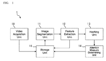
- FIG. 1 is a block diagram representing the functions of a visual attention detector according to a first embodiment.
- the visual attention detector 1 in FIG. 1 includes mainly, a video acquisition unit 10, an image segmentation unit 11, a feature extraction unit 12, a hashing unit 13, an attention measure determining unit 14, and a storage unit 15.
- the video acquisition unit 10 acquires the video that will be examined.
- the video acquisition unit 10 may acquire video data from an imaging device (e.g. a video camera), or may read video data from a storage device or from a server on a network.
- the video data is a 30-frame-per-second gray scale video acquired from a surveillance camera.
- the video format is not particularly limited, and a color video may be used.
- the input video acquired is stored in the storage unit 15.
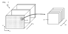
- the image segmentation unit 11 divides the input video along a timescale (t), and along spatial coordinates (x, y), to generate a plurality of image blocks.
- An image block is a set of images made up of local images of an identical spatial position from a plurality of frames, and is referred to as a cuboid or a spatiotemporal image.
- An image block may be thought of as a video of a localized time period in a local region within the input video.
- image features are extracted and evaluated on an image block basis to define the spatial and temporal changes in an image.
- FIG. 2 is a schematic of the relationship between an input video 20, a local image 21, and an image block 22.
- the input video 20 is a one-minute VGA (640 x 480 pixels) video running at 30 frames per second, and an image block 20 is five frames of 5 x 5 pixels, then the input video 20 is segmented into 73,728 image blocks 22.
- VGA 640 x 480 pixels
- the feature extraction unit 12 extracts spatiotemporal features from each image block 22.
- a spatiotemporal feature is an image feature representing both the spatial changes and the temporal changes in an image, and is an index quantifying the movement or changes in the subject (a person or an object, or the like) within a video. While in the embodiments a Histogram of Optical Flow (HOF) is used to represent the spatiotemporal features, other types of spatiotemporal features such as motion vectors may be used for this algorithm.
- HAF Histogram of Optical Flow
- FIG. 3 diagrams the HOF concept.
- the feature extraction unit 12 searches each frame in an image block 22 for feature points 30, and searches for movement of the feature points 30 by mapping the feature points 30 between frames. This movement of the feature points 30 is referred to as an optical flow 31.
- the feature extraction unit 12 then obtains the direction (angle) ⁇ , and speed (intensity) v of the optical flow for each of the feature points 30, and plots frequency of the direction ⁇ and the speed v of the optical flow 31 of each of the feature points 30 in a histogram 32 with the direction ⁇ and the speed v along the horizontal axis.
- This kind of operation is used to convert the plurality of optical flows 31 extracted from the image block 22 into a single histogram 32.
- This histogram 32 is an HOF. For example, when the direction ⁇ is separated into eight bins, and the speed v is separated into 10 bins, the HOF becomes an 18-dimensional feature vector.
- the hashing unit 13 uses a hash function to convert the value of the spatiotemporal feature into a hash value, and references a hash table to obtain the entry mapped to that hash value.
- the hash function converts the data input therein (in this embodiment the HOF), into a hash value that is made up of a simple bit string.
- Various kinds of hash functions have been heretofore proposed, and any kind of hash function may be used in this algorithm.
- LSH locality-sensitive hashing
- LSH is advantageous because, for instance, no teaching signals are required when generating the hash function, the function is fast, and there is a high probability that similar data is converted to the same hash value, and the like; and so LSH is effective for the real time analysis of the kinds of video signals that would be handled by this embodiment.
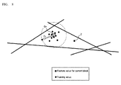
- FIG. 4 is a diagram outlining a hash function concept, specifically of locality-sensitive hashing (LSH).
- An LSH hash function g(x) is composed of k number of hyperplanes h(x) - hk(x) randomly distributed over an n-dimensional feature space.
- the hashing unit 13 determines whether the value x is on the positive or negative side of the hyperplane h1(x), and encodes the location of the value x as 1 (positive) or 0 (negative) for the hyperplane h1(x).
- the hashing unit 13 carries out identical determinations for the remaining hyperplanes h2(x) - hk(x), and creates a k-bit hash value by combining the individually encoded k bits. In the example illustrated in FIG.
- the value x1 is negative in h1(x), h3(x), and h4(x), and positive in h2(x), and h5(x); therefore, the hash value for the value x1 is "01001".
- the value x2 is negative in h2(x) and h3(x), and positive in h1(x), h4(x), and h5(x); therefore, the hash value for the value x2 is "10011".
- FIG. 5A outlines a hash table.
- a hash table is an array of data made up of a plurality of buckets; each bucket contains a hash value and an entry mapped to the hash value, and the hash value serves as an index to the bucket.
- the sample data for a spatiotemporal feature that generates a given hash value is registered in a bucket as an entry mapped to that hash value.
- Sample data may be the data acquired and accumulated through training using the video.
- FIG. 5B is a schematic representation of the relationship between a hash table, a hash function, and an entry.
- a subspace segmented by the hash function (into hyperplanes h1(x) - hk(x)) is mapped to buckets in the hash table, and the sample data plotted in the subspace is mapped to an entry registered in a bucket.
- two or more entries may be registered to a single bucket; conversely, there may be buckets that do not include a single entry.
- the attention measure determining unit 14 uses the hashing results to obtain attention measures for each of the image blocks 22 and generate an attention map.
- the attention measure determining unit 14 is described later in detail.
- the visual attention detector 1 may be composed of, for instance, a computer equipped with a CPU (processor), a memory, and auxiliary storage device, an input device, a display device, and a communication device.
- a CPU processor
- a memory e.g., RAM
- auxiliary storage device e.g., ROM
- input device e.g., keyboard
- display device e.g., a display
- communication device e.g., a communication device.
- Each function illustrated in the visual attention detector 1 FIG. 1
- Each function illustrated in the visual attention detector 1 may be implemented by loading a program stored in the auxiliary storage device into memory, and running the program on the CPU.
- all or a portion of the functions of the visual attention detector 1 may be implemented as circuits on an ASIC or an FPGA or the like.
- all or a portion of the functions of the visual attention detector 1 may be implemented through cloud computing or distributed computing.
- FIG. 6 is a flowchart of the hash table training process.
- the hash table training process generates a new hash function or a new hash table, and may be executed when the visual attention detector 1 is installed or begins operation.
- the video acquisition unit 10 obtains the video used for training in step S600.
- the training video may be a video captured for a predetermined period for an object captured such as a place, or a subject, and imaging conditions such as the angle, magnification, exposure, frame rate, and the like, that are identical to the types of videos that will be processed for visual attention detection (later described). Selecting a training video in this manner, allows the algorithm to learn the normal state of movement or change in the subject within a video. For instance, if the visual attention detector 1 is adopted in a surveillance camera for detecting abnormalities, a video captured by the surveillance camera over a few minutes or a few hours may be used for training.
- step S601 the image segmentation unit 11 divides the training video into image blocks ( FIG. 2 ).
- step S602 the feature extraction unit 12 calculates the features in each image block.
- the feature data calculated at this point are stored in the storage unit 15. Note that the processing in steps S601 and S602 may be executed consecutively each time the required number of frames of the video data is read (i.e., five frames in the example in FIG. 2 ).
- a plurality of sets of hash functions and hash tables are created from the same training feature data to improve the reliability of the hashing process.
- the hashing unit 13 randomly generates hash functions (i.e., k hyperplanes; step S603), generates an array of 2k new buckets for use in the hash table, and initializes each bucket (Step S604).
- the hashing unit 13 takes out a single value from the training feature data (hereinafter, training value) and converts the training value to a hash value using the hash function generated in step S603 (Step S605).
- the hashing unit 13 registers the training value in the bucket mapped to the hash value obtained in step S605 (step S606). After executing the steps S605 and S606 for all the training values contained in the training feature data (step S607), the hash table is complete.
- FIG. 7 is a flowchart of a visual attention detection process.
- the visual attention detection process is executed continually or periodically while the visual attention detector 1 is running.
- the video acquisition unit 10 obtains the video to be analyzed in step S700.
- the video acquisition unit 10 may acquire five frames of video data from a surveillance camera.
- the image segmentation unit 11 divides the training video into image blocks ( FIG. 2 ).
- the feature extraction unit 12 calculates the features in each image block. The feature data calculated at this point are stored in the storage unit 15.
- steps S703 to S708 are run in order on each of the image blocks within the video.
- the "current block” refers to an image block being processed.
- the hashing unit 13 acquires an entry (training value) in the bucket mapped to the hash value for the current block from the i-th hash table (step S705). If there is not at least one training value contained in the bucket mapped to the hash value (hereafter, empty bucket), instead of processing the empty bucket, an entry may be acquired from a bucket containing the closest training value to the value of the feature in the current block (referred to as a neighboring bucket).
- the training value obtained in step S705 is referred to hereafter as a "mapped training value".
- a mapped training value may often include a plurality of training values, however there are cases where the mapped training value contains only a single training value.
- the attention measure determining unit 14 then computes an attention measure for the current block on the basis of the distance between the value of the feature in the current block and the mapped training value in a feature space (step S706).
- an attention measure A i (z) is computed for the current block using the following formula.
- a i z 1 ⁇ 1 1 + exp ⁇ ⁇ r m / ⁇ z ⁇ c m ⁇ 2 2 ⁇ 1
- steps S703 through S706 are repeated while changing the hash functions and hash tables selected, to thereby compute L number of attention measures A 1 (z) - A L (z).
- the attention measure determining unit 14 combines the attention measures A 1 (z) - A L (z) obtained with each of the hash tables to thereby compute a final attention measure A(z).
- Any desired method may be used to combine the attention measures; in the embodiment the following kind of weighted sum formula is used.
- FIG. 9 diagrams an example of a video 90 and an attention map 91.
- the attention map 91 represents the attention measure for each image block in gray scale, where, the brighter (i.e., the closer to white) the image block, the higher the attention measure.
- the video 90 represents a person 92 and an object (a vehicle) 93 as the moving subjects, only the region including the person 92 has a larger attention measure in the attention map 91.
- images of a traveling vehicle are commonplace (normal) in a video from a surveillance camera along a highway; however, an image of a person walking along the highway would be out of place (abnormal).
- the region including the person 92, which is where there is abnormal movement is detected as having larger attention measure.
- This kind of attention map is saved in the storage unit 15 or output to an external device, for use in various computer vision applications such as object recognition, image recognition or the like.
- a training value registered in the hash table for a spatiotemporal feature represents a normal state of change or movement in the subject (a normal value)
- the feature value for a current block represents the movement of or changes in the subject detected from the video being analyzed, in other words, the feature value for the current block represents the current state. Accordingly, evaluating the size of the distance between a feature value in a current block and the mapped training value in the feature space is equivalent to evaluating how much the current movement of or changes in the subject differs from its normal state.
- a subject's movement or change that differs from a normal state usually tends to attract a person's visual attention. Therefore, the visual attention detection algorithm of the embodiment is capable of accurately detecting (predicting) a visual attention region.
- the embodiment also selects a training value mapped to the hash value for the current block using a hash table wherein a training value learned in advance for a spatiotemporal feature is registered in a bucket mapped to a hash value.
- the training value distribution that should be compared to the spatiotemporal feature value for the current block may be simply and quickly selected from among all the training values.
- the embodiment may use training only for registering training values to the hash table without needing the design of a complicated model as required by conventional model-based techniques. Consequently, this simplifies implementation of a visual attention detector.
- Another advantage is that the algorithm may flexibly modified for changes in the detection target or environment by merely updating the hash table.
- the embodiment uses a plurality of hash tables, and combines the plurality of calculation results to obtain a final attention measure; therefore, with this embodiment it is possible to suppress degradation of the reliability of the visual attention detection due to bias in the training value distribution, or bias in the hash function, or the like to thereby implement highly reliable visual attention detection.
- the attention map constructed in the first embodiment uses the attention measures calculated per image block; consequently, there are cases where an attention measure distribution does not coincide with the regions identified in the video (i.e., the person 92, and the vehicle 93).
- visual attention is usually drawn toward a person or an object; therefore it is preferable then that the attention measures are output per region for a person or an object and not per image block. Therefore, a second embodiment may be configured to extract a foreground region in the video, and to refine the attention map on the basis of that foreground region.
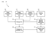
- FIG. 10 is a block diagram representing the functions of a visual attention detector 1 according to the second embodiment.
- the difference with the first embodiment ( FIG. 1 ) is the presence of a foreground extraction unit 16 and an attention map refinement unit 17. All other components are identical to the configuration in the first embodiment.
- the foreground extraction unit 16 extracts a "moving region" within a frame in a video for use as the foreground region. More specifically, the foreground extraction unit 16 uses the optical flow obtained when the feature extraction unit 12 calculates the spatiotemporal features, and determines the foreground region as those regions where the intensity of the optical flow (speed) is greater than a threshold. Using this already generated optical flow minimizes the amount of calculation needed for foreground extraction, and speeds up processing. Note that despite the increase in computations that would be needed compared to the optical flow algorithm used in this embodiment, other foreground extraction algorithms such as video segmentation, or motion clustering may be used.
- the attention map refinement unit 17 refines the attention map on the basis of information on the foreground region obtained from the foreground extraction unit 16 so that the attention measures within each of the foreground extraction regions are uniform. More specifically, when a plurality of image blocks overlaps within a single foreground region, the attention map refinement unit 17 sets the attention measure for that foreground region to the maximum attention measure in the overlapping image blocks.
- FIG. 11 depicts examples of the video 90, the attention map 91, foreground region information 94, and a refined attention map 95. It can be understood from FIG. 11 that the refined attention map includes smoother attention measures, and the attention measures are more uniform per region. In this manner the embodiment outputs an attention measure for each foreground region (moving region) and thereby improves the reliability of the visual attention detection.
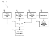
- FIG. 12 is a block diagram representing the functions of a visual attention detector 1 according to a third embodiment.
- the difference with the first embodiment ( FIG. 1 ) is the presence of a hash table updating unit 18. All other components are identical to the configuration in the first embodiment.
- the hash table updating unit 18 performs online updating of the hash tables.
- “online” means while the visual attention detector is operating (running). More specifically, the hash table updating unit 18 periodically performs the following two kinds of updating: “additions” or “deletions” (e.g., once every 30 minutes, once per day, once a week, or the like).
- An “addition” is an updating operation where the spatiotemporal feature value obtained from a video being process is registered to a hash table as a new training value. This kind of updating operation additionally trains the hash table on the current state, and therefore improves the reliability of the visual attention detection.
- All the values obtained from the video currently being processed may be added to the hash table; however, this may dramatically increase the number of entries registered in the hash table, which raises issues such as reduced storage capacity, and reduced processing speed. Accordingly, instead of adding all the values, it is preferable to only add those training values that satisfy a predetermined criterion.
- step S705 when the bucket corresponding to the hash value for the current block is empty, the attention measure determination unit calculates an attention measure A(z) using a training value contained in a neighboring bucket instead of the empty bucket.
- the storage unit 15 may temporarily store the feature value of the current block.
- the hash table updating unit 18 may register those feature values in an empty bucket of the hash table. The number of buckets used for calculating the attention measure increases, and thereby improves the reliability of hashing and the reliability of the visual attention detection.
- a “deletion” is an updating operation whereby the buckets containing less than a threshold Tb number of registered training values are deleted.
- To "delete a bucket” means to delete all the training values registered in the bucket (i.e., emptying the bucket). Using a bucket with few training values is likely to increase the prediction error in the attention measure. Consequently, deleting a bucket with few training values so that the bucket is not used when calculating the attention measure thereby improves the reliability and stability of the visual attention detection.
- the embodiment implements automatic online updating of a hash table, and therefore allows the algorithm to flexibly adapt to changes, such as in the detection target or the environment.
- the online updating function described for the third embodiment may be built into the device according to the second embodiment.
- a device according to the third embodiment can also use the feature values accumulated in the storage unit 15 to generate a new hash table.
Landscapes
- Engineering & Computer Science (AREA)
- Theoretical Computer Science (AREA)
- Physics & Mathematics (AREA)
- General Physics & Mathematics (AREA)
- Multimedia (AREA)
- Computer Vision & Pattern Recognition (AREA)
- General Engineering & Computer Science (AREA)
- Data Mining & Analysis (AREA)
- Life Sciences & Earth Sciences (AREA)
- Biodiversity & Conservation Biology (AREA)
- Health & Medical Sciences (AREA)
- General Health & Medical Sciences (AREA)
- Databases & Information Systems (AREA)
- Library & Information Science (AREA)
- Biomedical Technology (AREA)
- Molecular Biology (AREA)
- Mathematical Physics (AREA)
- Computing Systems (AREA)
- Evolutionary Computation (AREA)
- Software Systems (AREA)
- Computational Linguistics (AREA)
- Artificial Intelligence (AREA)
- Bioinformatics & Cheminformatics (AREA)
- Bioinformatics & Computational Biology (AREA)
- Evolutionary Biology (AREA)
- Probability & Statistics with Applications (AREA)
- Image Analysis (AREA)
- Closed-Circuit Television Systems (AREA)
- Studio Devices (AREA)
Description
- The present invention relates to techniques for predicting a region within a video likely to attract visual attention.
- There are techniques known, for instance from Japanese Unexamined Patent Application Publication No.
2010-258914 - Algorithms for visual attention detection can be largely divided into model-based techniques or learning-based techniques. In a model-based technique, image features that should be determined as abnormal are presented as the model, and the regions having these kinds of image features are extracted from an image. However, positing unknown abnormal states is non-trivial, and it tends to be extremely difficult to implement a model capable of supporting a variety of real world events. In contrast, a learning-based technique uses a large quantity of training data to learn the image features that should be determined as normal or abnormal. The advantage is that the learning-based method can provide a simpler way of building a highly accurate detector without requiring models or hypotheses. Unfortunately, this method is highly dependent on the training data; thus, the detection accuracy deteriorates when the training data is unsuitable. There are also cases where over time the subject being monitored, the situation, and the environment changes, and the knowledge gained through training becomes unsuitable even when the detector is trained in advance with suitable training data. In such a cases, new training data corresponding to the current situation must be prepared and used to retrain the detector, and maintenance of the detector is a hassle.
- Given the foregoing issues the present invention provides a novel algorithm for visual attention detection in videos that can be easily implemented and is of superior reliability.
- The proposed algorithm for visual attention detection in videos is also capable of flexibly adapting to changes in the detection target or environment, or the like.
- With the above in mind, the present invention adopts the following configurations.
- Specifically, a visual attention detector according to embodiments of the invention detects regions in a video likely to attract visual attention, and includes: a feature extraction unit configured to extract a spatiotemporal feature from a local region in a video, a spatiotemporal feature representing a spatial and a temporal change in an image in the local region; a hashing unit configured to convert a spatiotemporal feature value for the local region into a hash value using a hash function, and to select a training value mapped to the hash value for the local region using a hash table wherein a training value learned in advance for a spatiotemporal feature is registered in a bucket mapped to a hash value; and an attention measure determining unit for determining an attention measure on the basis of the distance between a spatiotemporal feature value for the local region and the selected training value such that the larger the distance the larger the attention measure.
- Note that a "spatiotemporal feature" can be considered an index that quantifies the movement or changes in the subject within the video. Consequently, a "training value for a spatiotemporal feature" represents a normal state of change or movement in the subject (a normal value), whereas, a "spatiotemporal feature value in a local region" represents the movement of or changes in the subject detected from the video being analyzed, in other words a spatiotemporal feature value represents the current state. Accordingly, evaluating the size of the distance between a "spatiotemporal feature value in a local region" and the "selected training value" is equivalent to evaluating how much the current movement of or changes in the subject differs from its normal state. A subject's movement or change that differs from a normal state usually tends to attract a person's visual attention. Therefore, determining an attention measure on the same basis, the size of the distance between a "spatiotemporal feature value in a local region" and the "selected training value" as in embodiments of the invention allows for accurate detection (prediction) of a visual attention region.
- Embodiments of the invention also select a training value mapped to the hash value for the local region using a hash table wherein a training value learned in advance for a spatiotemporal feature is registered in a bucket mapped to a hash value. Hereby, the training value distribution that should be compared to the spatiotemporal feature value for the local region may be simply and quickly selected from among all the training values.
- Moreover embodiments of the present invention may use training only for registering training values to the hash table without needing the design of a complicated model as required by conventional model-based techniques. Consequently, this simplifies implementation of a visual attention detector. Another advantage is that the algorithm may be flexibly modified for changes in the detection target or environment by merely updating the hash table.
- The training value may be the spatiotemporal feature value extracted from a video capturing an identical subject under identical parameters as the video being processed during a predetermined time period. Thus the normal states of movement or change in the subject within a video may be appropriately learned by selecting this kind of training video.
- The hashing unit includes a plurality of hash tables; the attention measure determining unit may use each hash table in the plurality of hash tables to calculate a plurality of attention measures and may combine the plurality of attention measures to determine a final attention measure. The reliability of the attention measure results calculated may deteriorate due to a bias in a distribution of training values or a bias in the hash function. At that point, combining a plurality of the calculation results using the plurality of hash tables as above-mentioned improves the reliability of the visual attention detection.
- The visual attention detector may further include a hash table updating unit configured to register a spatiotemporal feature value for the local region as a new training value in the hash table to thereby update the hash table. Hereby, the hash table may be additionally trained using the current state (the spatiotemporal feature value for the local region); therefore, the reliability of the visual attention detection may be improved.
- The hash table updating unit may update the hash table by deleting a bucket having less than a threshold number of training values registered therein. Using a bucket with few training values is likely to increase the prediction error in the attention measure. Consequently, deleting a bucket with few training values so that the bucket is not used when calculating the attention measure thereby improves the reliability and stability of the visual attention detection.
- The visual attention detector may further include a foreground extraction unit for extracting a moving region within a frame in the video as a foreground region; and an attention map refining unit for generating a refined attention map from information on the attention measure determined by the attention measure determining unit, and information on the foreground region extracted by the foreground extraction unit so that the attention measure within the foreground region is uniform. Outputting an attention measure for each foreground region (moving region) thereby improves the reliability of the visual attention detection.
- Note that a visual attention detector having at least a portion of the above-mentioned features and functions lies within the scope of the invention. Note that a method for visual attention detection having at least a portion of the above-mentioned features and functions lies within the scope of the invention. Moreover, a program for executing these methods on a computer, or a computer readable medium storing such a program are also within the scope of the invention. The above-mentioned processes and features may be freely combined with each other insofar as is technically possible to configure the invention.
- The invention provides a novel algorithm for visual attention detection in videos that can be easily implemented and is of superior reliability. The proposed algorithm for visual attention detection in videos is also capable of flexibly adapting to changes in the detection target or environment, or the like.
-
-
FIG. 1 is a block diagram representing the functions of a visual attention detector according to a first embodiment; -
FIG. 2 is a schematic of the relationship between an input video, a local image, and an image block; -
FIG. 3 is a diagram of the HOF concept; -
FIG. 4 is a diagram outlining a hash function concept, specifically of locality-sensitive hashing (LSH); -
FIG. 5A outlines a hash table;FIG. 5B is a schematic representation of the relationship between a hash table, a hash function, and an entry; -
FIG. 6 is a flowchart of the hash table training process; -
FIG. 7 is a flowchart of a visual attention detection process; -
FIG. 8 is a diagram for explaining the formulas used to calculate an attention measure; -
FIG. 9 diagrams an example of a video and an attention map; -
FIG. 10 is a block diagram representing the functions of a visual attention detector according to a second embodiment; -
FIG. 11 is a diagram for explaining the refinement of an attention map using foreground region information; and -
FIG. 12 is a block diagram representing the functions of a visual attention detector according to a third embodiment. - The invention relates to a visual attention detection algorithm that, using a computer for image analysis, automatically predicts regions (i.e., visual attention regions) within a video likely to attract visual attention. The results of visual attention detection is visual attention information; for instance, the visual attention information may be represented as an attention map depicting a distribution of an attention measure for each pixel or small region; or, the visual attention information may be output in the form of a binary image wherein the attention map is converted to binary using a predetermined threshold. This kind of visual attention information is preferably employed in a variety of ways such as preprocessing in a computer vision application, e.g., partitioning image regions (segmentation), image classification, scene interpretation, image compression, facial recognition, and object recognition.
- One feature of the visual attention detection algorithm according to embodiments of the invention is that hashing techniques are adopted in evaluating an image feature and in evaluating an attention measure. Hashing is a technique used in various fields such as data searching, encryption, and electronic certification; however, there are no known examples of hashing being adopted in the visual attention detection.
- Examples of specific embodiments of a visual attention detection algorithm according to the invention are described below with reference to the drawings. However, the embodiments described below are merely examples of a preferred configuration, and are in no way meant to limit the scope of the invention.
-
FIG. 1 is a block diagram representing the functions of a visual attention detector according to a first embodiment. Thevisual attention detector 1 inFIG. 1 includes mainly, avideo acquisition unit 10, animage segmentation unit 11, afeature extraction unit 12, a hashingunit 13, an attentionmeasure determining unit 14, and astorage unit 15. - The
video acquisition unit 10 acquires the video that will be examined. Thevideo acquisition unit 10 may acquire video data from an imaging device (e.g. a video camera), or may read video data from a storage device or from a server on a network. In this embodiment the video data is a 30-frame-per-second gray scale video acquired from a surveillance camera. However, the video format is not particularly limited, and a color video may be used. The input video acquired is stored in thestorage unit 15. - The
image segmentation unit 11 divides the input video along a timescale (t), and along spatial coordinates (x, y), to generate a plurality of image blocks. An image block is a set of images made up of local images of an identical spatial position from a plurality of frames, and is referred to as a cuboid or a spatiotemporal image. An image block may be thought of as a video of a localized time period in a local region within the input video. In the embodiment, image features are extracted and evaluated on an image block basis to define the spatial and temporal changes in an image.FIG. 2 is a schematic of the relationship between aninput video 20, alocal image 21, and animage block 22. For instance, when theinput video 20 is a one-minute VGA (640 x 480 pixels) video running at 30 frames per second, and animage block 20 is five frames of 5 x 5 pixels, then theinput video 20 is segmented into 73,728 image blocks 22. - The
feature extraction unit 12 extracts spatiotemporal features from eachimage block 22. A spatiotemporal feature is an image feature representing both the spatial changes and the temporal changes in an image, and is an index quantifying the movement or changes in the subject (a person or an object, or the like) within a video. While in the embodiments a Histogram of Optical Flow (HOF) is used to represent the spatiotemporal features, other types of spatiotemporal features such as motion vectors may be used for this algorithm. -
FIG. 3 diagrams the HOF concept. Thefeature extraction unit 12 searches each frame in animage block 22 for feature points 30, and searches for movement of the feature points 30 by mapping the feature points 30 between frames. This movement of the feature points 30 is referred to as anoptical flow 31. Thefeature extraction unit 12 then obtains the direction (angle) θ, and speed (intensity) v of the optical flow for each of the feature points 30, and plots frequency of the direction θ and the speed v of theoptical flow 31 of each of the feature points 30 in ahistogram 32 with the direction θ and the speed v along the horizontal axis. This kind of operation is used to convert the plurality ofoptical flows 31 extracted from theimage block 22 into asingle histogram 32. Thishistogram 32 is an HOF. For example, when the direction θ is separated into eight bins, and the speed v is separated into 10 bins, the HOF becomes an 18-dimensional feature vector. - The hashing
unit 13 uses a hash function to convert the value of the spatiotemporal feature into a hash value, and references a hash table to obtain the entry mapped to that hash value. - The hash function converts the data input therein (in this embodiment the HOF), into a hash value that is made up of a simple bit string. Various kinds of hash functions have been heretofore proposed, and any kind of hash function may be used in this algorithm. Below is an example of using locality-sensitive hashing (LSH). LSH is advantageous because, for instance, no teaching signals are required when generating the hash function, the function is fast, and there is a high probability that similar data is converted to the same hash value, and the like; and so LSH is effective for the real time analysis of the kinds of video signals that would be handled by this embodiment.
-
FIG. 4 is a diagram outlining a hash function concept, specifically of locality-sensitive hashing (LSH). An LSH hash function g(x) is composed of k number of hyperplanes h(x) - hk(x) randomly distributed over an n-dimensional feature space. AlthoughFIG. 4 depicts an example where n = 2 and k = 5 (and in this case, the hyperplanes are straight lines), for the sake of convenience, when implementing the algorithm the feature space may have several to several hundred dimensions n, and there may be several to several hundred hyperplanes k. - When a feature value x (where x is an n-dimensional vector) is input into the hashing
unit 13, the hashingunit 13 determines whether the value x is on the positive or negative side of the hyperplane h1(x), and encodes the location of the value x as 1 (positive) or 0 (negative) for the hyperplane h1(x). The hashingunit 13 carries out identical determinations for the remaining hyperplanes h2(x) - hk(x), and creates a k-bit hash value by combining the individually encoded k bits. In the example illustrated inFIG. 4 , the value x1 is negative in h1(x), h3(x), and h4(x), and positive in h2(x), and h5(x); therefore, the hash value for the value x1 is "01001". Furthermore, the value x2 is negative in h2(x) and h3(x), and positive in h1(x), h4(x), and h5(x); therefore, the hash value for the value x2 is "10011". -
FIG. 5A outlines a hash table. A hash table is an array of data made up of a plurality of buckets; each bucket contains a hash value and an entry mapped to the hash value, and the hash value serves as an index to the bucket. In the embodiment, the sample data for a spatiotemporal feature that generates a given hash value is registered in a bucket as an entry mapped to that hash value. Sample data may be the data acquired and accumulated through training using the video. -
FIG. 5B is a schematic representation of the relationship between a hash table, a hash function, and an entry. A subspace segmented by the hash function (into hyperplanes h1(x) - hk(x)) is mapped to buckets in the hash table, and the sample data plotted in the subspace is mapped to an entry registered in a bucket. As can be understood fromFIG. 5B , two or more entries may be registered to a single bucket; conversely, there may be buckets that do not include a single entry. - The attention
measure determining unit 14 uses the hashing results to obtain attention measures for each of the image blocks 22 and generate an attention map. The attentionmeasure determining unit 14 is described later in detail. - The
visual attention detector 1 may be composed of, for instance, a computer equipped with a CPU (processor), a memory, and auxiliary storage device, an input device, a display device, and a communication device. Each function illustrated in the visual attention detector 1 (FIG. 1 ) may be implemented by loading a program stored in the auxiliary storage device into memory, and running the program on the CPU. However, all or a portion of the functions of thevisual attention detector 1 may be implemented as circuits on an ASIC or an FPGA or the like. Alternatively, all or a portion of the functions of thevisual attention detector 1 may be implemented through cloud computing or distributed computing. - Details of the
visual attention detector 1 training with a hash table are described with reference toFIG. 6. FIG. 6 is a flowchart of the hash table training process. The hash table training process generates a new hash function or a new hash table, and may be executed when thevisual attention detector 1 is installed or begins operation. - The
video acquisition unit 10 obtains the video used for training in step S600. The training video may be a video captured for a predetermined period for an object captured such as a place, or a subject, and imaging conditions such as the angle, magnification, exposure, frame rate, and the like, that are identical to the types of videos that will be processed for visual attention detection (later described). Selecting a training video in this manner, allows the algorithm to learn the normal state of movement or change in the subject within a video. For instance, if thevisual attention detector 1 is adopted in a surveillance camera for detecting abnormalities, a video captured by the surveillance camera over a few minutes or a few hours may be used for training. - In step S601 the
image segmentation unit 11 divides the training video into image blocks (FIG. 2 ). In step S602 thefeature extraction unit 12 calculates the features in each image block. The feature data calculated at this point are stored in thestorage unit 15. Note that the processing in steps S601 and S602 may be executed consecutively each time the required number of frames of the video data is read (i.e., five frames in the example inFIG. 2 ). - After acquiring the training feature data as above described, control transitions to generating a hash function and a hash table. In the embodiment, a plurality of sets of hash functions and hash tables are created from the same training feature data to improve the reliability of the hashing process.
- First, the hashing
unit 13 randomly generates hash functions (i.e., k hyperplanes; step S603), generates an array of 2k new buckets for use in the hash table, and initializes each bucket (Step S604). Next, the hashingunit 13 takes out a single value from the training feature data (hereinafter, training value) and converts the training value to a hash value using the hash function generated in step S603 (Step S605). The hashingunit 13 registers the training value in the bucket mapped to the hash value obtained in step S605 (step S606). After executing the steps S605 and S606 for all the training values contained in the training feature data (step S607), the hash table is complete. - Further, repeating the steps S603 to S607 L times creates L sets of hash functions and hash tables. The value of L may be selected as desired through experimentation or experience (in the embodiment, assume L = 10). The hash table training process is hereby complete.
- Details of the visual attention detection process in the
visual attention detector 1 are described with reference toFIG. 7. FIG. 7 is a flowchart of a visual attention detection process. The visual attention detection process is executed continually or periodically while thevisual attention detector 1 is running. - The
video acquisition unit 10 obtains the video to be analyzed in step S700. For instance, thevideo acquisition unit 10 may acquire five frames of video data from a surveillance camera. In step S701 theimage segmentation unit 11 divides the training video into image blocks (FIG. 2 ). In step S702 thefeature extraction unit 12 calculates the features in each image block. The feature data calculated at this point are stored in thestorage unit 15. - Subsequently, the processes in steps S703 to S708 are run in order on each of the image blocks within the video. Hereafter, the "current block" refers to an image block being processed.
- First, the hashing
unit 13 converts the values of the features in the current block into a hash value using the i-th hash function, where i = 1 to L (steps S703, S704). The hashingunit 13 acquires an entry (training value) in the bucket mapped to the hash value for the current block from the i-th hash table (step S705). If there is not at least one training value contained in the bucket mapped to the hash value (hereafter, empty bucket), instead of processing the empty bucket, an entry may be acquired from a bucket containing the closest training value to the value of the feature in the current block (referred to as a neighboring bucket). The training value obtained in step S705 is referred to hereafter as a "mapped training value". A mapped training value may often include a plurality of training values, however there are cases where the mapped training value contains only a single training value. - The attention
measure determining unit 14 then computes an attention measure for the current block on the basis of the distance between the value of the feature in the current block and the mapped training value in a feature space (step S706). In the embodiment an attention measure Ai(z) is computed for the current block using the following formula.
- Here, "i" is the number of the hash table, where i = 1 - L; z represents the value of the feature (feature vector) for the current block; cm is the center (center of gravity) for the distribution of mapped training values; and rm is distance between the center (center of gravity) and an outermost training value in the distribution of mapped training values (
FIG. 8 ). - The processes in steps S703 through S706 are repeated while changing the hash functions and hash tables selected, to thereby compute L number of attention measures A1(z) - AL(z). Finally the attention
measure determining unit 14 combines the attention measures A1(z) - AL(z) obtained with each of the hash tables to thereby compute a final attention measure A(z). Any desired method may be used to combine the attention measures; in the embodiment the following kind of weighted sum formula is used.
- Here, α1 is a weight that may be established as appropriate based on experimentation or experience. For instance, the reliability of the hash table may be evaluated and a hash table with a low reliability given a smaller weight, while a hash table with a high reliability is given a larger weight. The reliability of a hash table may be evaluated using the distribution of the training values within each bucket, the degree of separation between training value distributions between buckets, or the bias in the number of training values between buckets. Of course, all the weights may be made equal by, for instance α1,...,αL=1/L, or the like.
- Once an attention measure A(z) is computed for all the image blocks in a video, the attention
measure determining unit 14 generates an attention map.FIG. 9 diagrams an example of avideo 90 and anattention map 91. Theattention map 91 represents the attention measure for each image block in gray scale, where, the brighter (i.e., the closer to white) the image block, the higher the attention measure. Although thevideo 90 represents aperson 92 and an object (a vehicle) 93 as the moving subjects, only the region including theperson 92 has a larger attention measure in theattention map 91. For example, images of a traveling vehicle are commonplace (normal) in a video from a surveillance camera along a highway; however, an image of a person walking along the highway would be out of place (abnormal). In such a situation, the region including theperson 92, which is where there is abnormal movement, is detected as having larger attention measure. This kind of attention map is saved in thestorage unit 15 or output to an external device, for use in various computer vision applications such as object recognition, image recognition or the like. - A training value registered in the hash table for a spatiotemporal feature represents a normal state of change or movement in the subject (a normal value), whereas, the feature value for a current block represents the movement of or changes in the subject detected from the video being analyzed, in other words, the feature value for the current block represents the current state. Accordingly, evaluating the size of the distance between a feature value in a current block and the mapped training value in the feature space is equivalent to evaluating how much the current movement of or changes in the subject differs from its normal state. A subject's movement or change that differs from a normal state usually tends to attract a person's visual attention. Therefore, the visual attention detection algorithm of the embodiment is capable of accurately detecting (predicting) a visual attention region.
- The embodiment also selects a training value mapped to the hash value for the current block using a hash table wherein a training value learned in advance for a spatiotemporal feature is registered in a bucket mapped to a hash value. Hereby, the training value distribution that should be compared to the spatiotemporal feature value for the current block may be simply and quickly selected from among all the training values.
- Moreover the embodiment may use training only for registering training values to the hash table without needing the design of a complicated model as required by conventional model-based techniques. Consequently, this simplifies implementation of a visual attention detector. Another advantage is that the algorithm may flexibly modified for changes in the detection target or environment by merely updating the hash table. Finally, the embodiment uses a plurality of hash tables, and combines the plurality of calculation results to obtain a final attention measure; therefore, with this embodiment it is possible to suppress degradation of the reliability of the visual attention detection due to bias in the training value distribution, or bias in the hash function, or the like to thereby implement highly reliable visual attention detection.
- The attention map constructed in the first embodiment uses the attention measures calculated per image block; consequently, there are cases where an attention measure distribution does not coincide with the regions identified in the video (i.e., the
person 92, and the vehicle 93). However, visual attention is usually drawn toward a person or an object; therefore it is preferable then that the attention measures are output per region for a person or an object and not per image block. Therefore, a second embodiment may be configured to extract a foreground region in the video, and to refine the attention map on the basis of that foreground region. -
FIG. 10 is a block diagram representing the functions of avisual attention detector 1 according to the second embodiment. The difference with the first embodiment (FIG. 1 ) is the presence of aforeground extraction unit 16 and an attentionmap refinement unit 17. All other components are identical to the configuration in the first embodiment. - The
foreground extraction unit 16 extracts a "moving region" within a frame in a video for use as the foreground region. More specifically, theforeground extraction unit 16 uses the optical flow obtained when thefeature extraction unit 12 calculates the spatiotemporal features, and determines the foreground region as those regions where the intensity of the optical flow (speed) is greater than a threshold. Using this already generated optical flow minimizes the amount of calculation needed for foreground extraction, and speeds up processing. Note that despite the increase in computations that would be needed compared to the optical flow algorithm used in this embodiment, other foreground extraction algorithms such as video segmentation, or motion clustering may be used. - The attention
map refinement unit 17 refines the attention map on the basis of information on the foreground region obtained from theforeground extraction unit 16 so that the attention measures within each of the foreground extraction regions are uniform. More specifically, when a plurality of image blocks overlaps within a single foreground region, the attentionmap refinement unit 17 sets the attention measure for that foreground region to the maximum attention measure in the overlapping image blocks. -
FIG. 11 depicts examples of thevideo 90, theattention map 91, foregroundregion information 94, and arefined attention map 95. It can be understood fromFIG. 11 that the refined attention map includes smoother attention measures, and the attention measures are more uniform per region. In this manner the embodiment outputs an attention measure for each foreground region (moving region) and thereby improves the reliability of the visual attention detection. -
FIG. 12 is a block diagram representing the functions of avisual attention detector 1 according to a third embodiment. The difference with the first embodiment (FIG. 1 ) is the presence of a hashtable updating unit 18. All other components are identical to the configuration in the first embodiment. - The hash
table updating unit 18 performs online updating of the hash tables. Here, "online" means while the visual attention detector is operating (running). More specifically, the hashtable updating unit 18 periodically performs the following two kinds of updating: "additions" or "deletions" (e.g., once every 30 minutes, once per day, once a week, or the like). - An "addition" is an updating operation where the spatiotemporal feature value obtained from a video being process is registered to a hash table as a new training value. This kind of updating operation additionally trains the hash table on the current state, and therefore improves the reliability of the visual attention detection.
- All the values obtained from the video currently being processed may be added to the hash table; however, this may dramatically increase the number of entries registered in the hash table, which raises issues such as reduced storage capacity, and reduced processing speed. Accordingly, instead of adding all the values, it is preferable to only add those training values that satisfy a predetermined criterion.
- For instance, in step S705 (
FIG. 7 ), when the bucket corresponding to the hash value for the current block is empty, the attention measure determination unit calculates an attention measure A(z) using a training value contained in a neighboring bucket instead of the empty bucket. At this point, if the attention measure A(z) calculated is smaller than a threshold THa (i.e., if it is determined that there is normal movement in the current block), then thestorage unit 15 may temporarily store the feature value of the current block. In this manner, on collecting a set number of feature values would belong to an empty bucket but are determined to be normal, the hashtable updating unit 18 may register those feature values in an empty bucket of the hash table. The number of buckets used for calculating the attention measure increases, and thereby improves the reliability of hashing and the reliability of the visual attention detection. - A "deletion" is an updating operation whereby the buckets containing less than a threshold Tb number of registered training values are deleted. To "delete a bucket" means to delete all the training values registered in the bucket (i.e., emptying the bucket). Using a bucket with few training values is likely to increase the prediction error in the attention measure. Consequently, deleting a bucket with few training values so that the bucket is not used when calculating the attention measure thereby improves the reliability and stability of the visual attention detection.
- As above described, the embodiment implements automatic online updating of a hash table, and therefore allows the algorithm to flexibly adapt to changes, such as in the detection target or the environment.
- The above-described embodiment is merely one specific example of the invention, and in no way is it meant that the scope of the invention is limited to said specific example. For example, the online updating function described for the third embodiment may be built into the device according to the second embodiment. Additionally, while the example provided through the third embodiment only adds and deletes training values from an existing hash table, a device according to the third embodiment can also use the feature values accumulated in the
storage unit 15 to generate a new hash table.
Claims (7)
- A visual attention detector configured to predict a region in a video likely to attract visual attention, the visual attention detector comprising:a feature extraction unit configured to extract a spatiotemporal feature from a local region in a video, a spatiotemporal feature representing a spatial and a temporal change in an image in the local region;a hashing unit configured to convert a spatiotemporal feature value for the local region into a hash value using a hash function, and to select a training value mapped to the hash value for the local region using a hash table wherein a training value learned in advance for a spatiotemporal feature is registered in a bucket mapped to a hash value; andan attention measure determining unit for determining an attention measure for the local region on the basis of the distance between a spatiotemporal feature value for the local region and the selected training value such that the larger the distance the larger the attention measure.
- The visual attention detector according to claim 1, wherein the training value is a spatiotemporal feature value extracted from a video capturing an identical subject under identical parameters as the video being processed during a predetermined time period.
- The visual attention detector according to claim 1 or claim 2, wherein: the hashing unit includes a plurality of hash tables; and
the attention measure determining unit computes a plurality of attention measures using each hash table in the plurality of hash tables, and combines the plurality of attention measures to thereby determine a final attention measure. - The visual attention detector according to any one of claims 1 through 3, further comprising: a hash table updating unit configured to register a spatiotemporal feature value for the local region as a new training value in the hash table to thereby update the hash table.
- The visual attention detector according to claim 4, wherein the hash table updating unit updates the hash table by deleting a bucket having less than a threshold number of training values registered therein.
- The visual attention detector according to any one of claims 1 through 5, further comprising: a foreground extraction unit configured to extract a moving region within a frame in the video as a foreground region; and
an attention map refining unit configured to generate a refined attention map from information related to the attention measure determined by the attention measure determining unit, and information on the foreground region extracted by the foreground extraction unit so that the attention measure within the foreground region is uniform. - A method of visual attention detection for predicting a region in a video likely to attract visual attention, the method of visual attention detection having steps comprising:extracting a spatiotemporal feature from a local region in a video, the spatiotemporal feature representing a spatial and a temporal change in an image in the local region;converting a spatiotemporal feature value of the local region into a hash value using a hash function;selecting a training value mapped to the hash value for the local region using a hash table wherein a training value learned in advance for a spatiotemporal feature is registered in a bucket mapped to a hash value; anddetermining an attention measure for the local region on the basis of the distance between a spatiotemporal feature value for the local region and the selected training value such that the larger the distance the larger the attention measure.
Applications Claiming Priority (1)
| Application Number | Priority Date | Filing Date | Title |
|---|---|---|---|
| CN201510633327.7A CN106557765A (en) | 2015-09-29 | 2015-09-29 | Note detection means and note detection method |
Publications (2)
| Publication Number | Publication Date |
|---|---|
| EP3151160A1 true EP3151160A1 (en) | 2017-04-05 |
| EP3151160B1 EP3151160B1 (en) | 2019-06-12 |
Family
ID=56979325
Family Applications (1)
| Application Number | Title | Priority Date | Filing Date |
|---|---|---|---|
| EP16183153.2A Active EP3151160B1 (en) | 2015-09-29 | 2016-08-08 | Visual attention detector and visual attention detection method |
Country Status (5)
| Country | Link |
|---|---|
| US (1) | US9904868B2 (en) |
| EP (1) | EP3151160B1 (en) |
| JP (1) | JP6565600B2 (en) |
| KR (1) | KR20170038144A (en) |
| CN (1) | CN106557765A (en) |
Cited By (1)
| Publication number | Priority date | Publication date | Assignee | Title |
|---|---|---|---|---|
| CN112559781A (en) * | 2020-12-10 | 2021-03-26 | 西北大学 | Image retrieval system and method |
Families Citing this family (11)
| Publication number | Priority date | Publication date | Assignee | Title |
|---|---|---|---|---|
| WO2017010514A1 (en) * | 2015-07-15 | 2017-01-19 | 日本電信電話株式会社 | Image retrieval device and method, photograph time estimation device and method, iterative structure extraction device and method, and program |
| JP6751691B2 (en) * | 2017-06-15 | 2020-09-09 | ルネサスエレクトロニクス株式会社 | Anomaly detector and vehicle system |
| KR102058393B1 (en) * | 2017-11-30 | 2019-12-23 | 국민대학교산학협력단 | Sketch-based media plagiarism inspection method and apparatus |
| US11454968B2 (en) * | 2018-02-28 | 2022-09-27 | Micron Technology, Inc. | Artificial neural network integrity verification |
| JP6742623B1 (en) * | 2019-11-13 | 2020-08-19 | 尚範 伊達 | Monitoring device, monitoring method, and program |
| SG10201913744SA (en) * | 2019-12-30 | 2020-12-30 | Sensetime Int Pte Ltd | Image processing method and apparatus, electronic device, and storage medium |
| CN115393246B (en) * | 2021-05-19 | 2026-02-13 | 佳能医疗系统株式会社 | Image segmentation systems and image segmentation methods |
| CN114330565A (en) * | 2021-12-31 | 2022-04-12 | 深圳集智数字科技有限公司 | Face recognition method and device |
| CN116414867B (en) * | 2023-06-12 | 2023-08-22 | 中南大学 | Space-time data retrieval method based on quantization hash coding |
| CN116719418B (en) * | 2023-08-09 | 2023-10-27 | 湖南马栏山视频先进技术研究院有限公司 | Method and device for checking gaze point prediction model |
| CN119380169B (en) * | 2024-12-27 | 2025-06-03 | 杭州海康机器人股份有限公司 | Visual detection configuration method, device and visual detection system |
Citations (5)
| Publication number | Priority date | Publication date | Assignee | Title |
|---|---|---|---|---|
| JP2010258914A (en) | 2009-04-27 | 2010-11-11 | Nippon Telegr & Teleph Corp <Ntt> | Striking area image generation method, saliency area image generation apparatus, program, and recording medium |
| US20120301105A1 (en) * | 2011-03-22 | 2012-11-29 | Georgia Tech Research Corporation | Systems and methods for retrieving casual sets of events from unstructured signals |
| CN104036287A (en) * | 2014-05-16 | 2014-09-10 | 同济大学 | Human movement significant trajectory-based video classification method |
| US20140304236A1 (en) * | 2013-04-05 | 2014-10-09 | Canon Kabushiki Kaisha | Hash value generation apparatus, system, determination method, program, and storage medium |
| CN104504365A (en) * | 2014-11-24 | 2015-04-08 | 闻泰通讯股份有限公司 | System and method for smiling face recognition in video sequence |
Family Cites Families (6)
| Publication number | Priority date | Publication date | Assignee | Title |
|---|---|---|---|---|
| CN101404032B (en) * | 2008-11-11 | 2011-09-28 | 清华大学 | Video retrieval method and system based on contents |
| US9092520B2 (en) * | 2011-06-20 | 2015-07-28 | Microsoft Technology Licensing, Llc | Near-duplicate video retrieval |
| US9165190B2 (en) * | 2012-09-12 | 2015-10-20 | Avigilon Fortress Corporation | 3D human pose and shape modeling |
| CN103096122B (en) * | 2013-01-24 | 2015-04-22 | 上海交通大学 | Stereoscopic vision comfort level evaluation method based on motion features inside area of interest |
| CN103336957B (en) * | 2013-07-18 | 2016-12-28 | 中国科学院自动化研究所 | A kind of network homology video detecting method based on space-time characteristic |
| US10452712B2 (en) * | 2013-10-21 | 2019-10-22 | Microsoft Technology Licensing, Llc | Mobile video search |
-
2015
- 2015-09-29 CN CN201510633327.7A patent/CN106557765A/en active Pending
- 2015-10-28 JP JP2015212207A patent/JP6565600B2/en active Active
-
2016
- 2016-08-08 EP EP16183153.2A patent/EP3151160B1/en active Active
- 2016-08-16 US US15/237,817 patent/US9904868B2/en active Active
- 2016-08-23 KR KR1020160106819A patent/KR20170038144A/en not_active Ceased
Patent Citations (5)
| Publication number | Priority date | Publication date | Assignee | Title |
|---|---|---|---|---|
| JP2010258914A (en) | 2009-04-27 | 2010-11-11 | Nippon Telegr & Teleph Corp <Ntt> | Striking area image generation method, saliency area image generation apparatus, program, and recording medium |
| US20120301105A1 (en) * | 2011-03-22 | 2012-11-29 | Georgia Tech Research Corporation | Systems and methods for retrieving casual sets of events from unstructured signals |
| US20140304236A1 (en) * | 2013-04-05 | 2014-10-09 | Canon Kabushiki Kaisha | Hash value generation apparatus, system, determination method, program, and storage medium |
| CN104036287A (en) * | 2014-05-16 | 2014-09-10 | 同济大学 | Human movement significant trajectory-based video classification method |
| CN104504365A (en) * | 2014-11-24 | 2015-04-08 | 闻泰通讯股份有限公司 | System and method for smiling face recognition in video sequence |
Non-Patent Citations (2)
| Title |
|---|
| CONG YANG ET AL: "Video Anomaly Search in Crowded Scenes via Spatio-Temporal Motion Context", IEEE TRANSACTIONS ON INFORMATION FORENSICS AND SECURITY, IEEE, PISCATAWAY, NJ, US, vol. 8, no. 10, 1 October 2013 (2013-10-01), pages 1590 - 1599, XP011526835, ISSN: 1556-6013, [retrieved on 20130909], DOI: 10.1109/TIFS.2013.2272243 * |
| JI R ET AL: "Actor-independent action search using spatiotemporal vocabulary with appearance hashing", PATTERN RECOGNITION, ELSEVIER, GB, vol. 44, no. 3, 1 March 2011 (2011-03-01), pages 624 - 638, XP027503088, ISSN: 0031-3203, [retrieved on 20101117], DOI: 10.1016/J.PATCOG.2010.08.022 * |
Cited By (1)
| Publication number | Priority date | Publication date | Assignee | Title |
|---|---|---|---|---|
| CN112559781A (en) * | 2020-12-10 | 2021-03-26 | 西北大学 | Image retrieval system and method |
Also Published As
| Publication number | Publication date |
|---|---|
| US9904868B2 (en) | 2018-02-27 |
| EP3151160B1 (en) | 2019-06-12 |
| KR20170038144A (en) | 2017-04-06 |
| JP6565600B2 (en) | 2019-08-28 |
| CN106557765A (en) | 2017-04-05 |
| US20170091573A1 (en) | 2017-03-30 |
| JP2017068815A (en) | 2017-04-06 |
Similar Documents
| Publication | Publication Date | Title |
|---|---|---|
| EP3151160B1 (en) | Visual attention detector and visual attention detection method | |
| CN105404884B (en) | Image analysis method | |
| EP2959454B1 (en) | Method, system and software module for foreground extraction | |
| US10489916B2 (en) | Method and apparatus for updating a background model | |
| CN110599503A (en) | Detection model training method and device, computer equipment and storage medium | |
| CN104615986B (en) | The method that pedestrian detection is carried out to the video image of scene changes using multi-detector | |
| Huang et al. | Automatic moving object extraction through a real-world variable-bandwidth network for traffic monitoring systems | |
| US20150310297A1 (en) | Systems and methods for computer vision background estimation using foreground-aware statistical models | |
| US20210342593A1 (en) | Method and apparatus for detecting target in video, computing device, and storage medium | |
| CN112101114B (en) | A video target detection method, device, equipment and storage medium | |
| CN113129335A (en) | Visual tracking algorithm and multi-template updating strategy based on twin network | |
| WO2019197021A1 (en) | Device and method for instance-level segmentation of an image | |
| CN111476059A (en) | Target detection method, device, computer equipment and storage medium | |
| CN115049954A (en) | Target identification method, device, electronic equipment and medium | |
| Ma et al. | A lightweight neural network for crowd analysis of images with congested scenes | |
| US12541873B2 (en) | Information processing apparatus and information processing method | |
| CN111681264A (en) | Real-time multi-target tracking method for monitoring scene | |
| KR101588648B1 (en) | A method on the pedestrian detection and tracking for intelligent video surveillance | |
| CN117576649A (en) | A lane line detection method and system based on segmentation points and dual feature enhancement | |
| KR101690050B1 (en) | Intelligent video security system | |
| CN106874843A (en) | A kind of method for tracking target and equipment | |
| CN120526469A (en) | A method and device for dynamic target recognition based on eye tracking of three-dimensional gaze points | |
| Deokate et al. | Deep Learning-Based Crowd Surveillance and Density Estimation | |
| Tsekhmystro et al. | Study of the dependence of accuracy in vehicles search on the size of the object using UAV images | |
| CN117496080A (en) | A dense reconstruction method, system, equipment and medium based on the combination of YOLOv5 network and dynamic SLAM |
Legal Events
| Date | Code | Title | Description |
|---|---|---|---|
| PUAI | Public reference made under article 153(3) epc to a published international application that has entered the european phase |
Free format text: ORIGINAL CODE: 0009012 |
|
| STAA | Information on the status of an ep patent application or granted ep patent |
Free format text: STATUS: THE APPLICATION HAS BEEN PUBLISHED |
|
| AK | Designated contracting states |
Kind code of ref document: A1 Designated state(s): AL AT BE BG CH CY CZ DE DK EE ES FI FR GB GR HR HU IE IS IT LI LT LU LV MC MK MT NL NO PL PT RO RS SE SI SK SM TR |
|
| AX | Request for extension of the european patent |
Extension state: BA ME |
|
| STAA | Information on the status of an ep patent application or granted ep patent |
Free format text: STATUS: REQUEST FOR EXAMINATION WAS MADE |
|
| 17P | Request for examination filed |
Effective date: 20171005 |
|
| RBV | Designated contracting states (corrected) |
Designated state(s): AL AT BE BG CH CY CZ DE DK EE ES FI FR GB GR HR HU IE IS IT LI LT LU LV MC MK MT NL NO PL PT RO RS SE SI SK SM TR |
|
| GRAP | Despatch of communication of intention to grant a patent |
Free format text: ORIGINAL CODE: EPIDOSNIGR1 |
|
| STAA | Information on the status of an ep patent application or granted ep patent |
Free format text: STATUS: GRANT OF PATENT IS INTENDED |
|
| INTG | Intention to grant announced |
Effective date: 20181121 |
|
| GRAS | Grant fee paid |
Free format text: ORIGINAL CODE: EPIDOSNIGR3 |
|
| GRAJ | Information related to disapproval of communication of intention to grant by the applicant or resumption of examination proceedings by the epo deleted |
Free format text: ORIGINAL CODE: EPIDOSDIGR1 |
|
| GRAL | Information related to payment of fee for publishing/printing deleted |
Free format text: ORIGINAL CODE: EPIDOSDIGR3 |
|
| STAA | Information on the status of an ep patent application or granted ep patent |
Free format text: STATUS: REQUEST FOR EXAMINATION WAS MADE |
|
| GRAR | Information related to intention to grant a patent recorded |
Free format text: ORIGINAL CODE: EPIDOSNIGR71 |
|
| STAA | Information on the status of an ep patent application or granted ep patent |
Free format text: STATUS: GRANT OF PATENT IS INTENDED |
|
| GRAA | (expected) grant |
Free format text: ORIGINAL CODE: 0009210 |
|
| STAA | Information on the status of an ep patent application or granted ep patent |
Free format text: STATUS: THE PATENT HAS BEEN GRANTED |
|
| INTC | Intention to grant announced (deleted) | ||
| AK | Designated contracting states |
Kind code of ref document: B1 Designated state(s): AL AT BE BG CH CY CZ DE DK EE ES FI FR GB GR HR HU IE IS IT LI LT LU LV MC MK MT NL NO PL PT RO RS SE SI SK SM TR |
|
| INTG | Intention to grant announced |
Effective date: 20190506 |
|
| REG | Reference to a national code |
Ref country code: GB Ref legal event code: FG4D |
|
| REG | Reference to a national code |
Ref country code: CH Ref legal event code: EP |
|
| REG | Reference to a national code |
Ref country code: AT Ref legal event code: REF Ref document number: 1143529 Country of ref document: AT Kind code of ref document: T Effective date: 20190615 |
|
| REG | Reference to a national code |
Ref country code: DE Ref legal event code: R096 Ref document number: 602016015066 Country of ref document: DE |
|
| REG | Reference to a national code |
Ref country code: IE Ref legal event code: FG4D |
|
| REG | Reference to a national code |
Ref country code: NL Ref legal event code: MP Effective date: 20190612 |
|
| REG | Reference to a national code |
Ref country code: LT Ref legal event code: MG4D |
|
| PG25 | Lapsed in a contracting state [announced via postgrant information from national office to epo] |
Ref country code: AL Free format text: LAPSE BECAUSE OF FAILURE TO SUBMIT A TRANSLATION OF THE DESCRIPTION OR TO PAY THE FEE WITHIN THE PRESCRIBED TIME-LIMIT Effective date: 20190612 Ref country code: NO Free format text: LAPSE BECAUSE OF FAILURE TO SUBMIT A TRANSLATION OF THE DESCRIPTION OR TO PAY THE FEE WITHIN THE PRESCRIBED TIME-LIMIT Effective date: 20190912 Ref country code: FI Free format text: LAPSE BECAUSE OF FAILURE TO SUBMIT A TRANSLATION OF THE DESCRIPTION OR TO PAY THE FEE WITHIN THE PRESCRIBED TIME-LIMIT Effective date: 20190612 Ref country code: SE Free format text: LAPSE BECAUSE OF FAILURE TO SUBMIT A TRANSLATION OF THE DESCRIPTION OR TO PAY THE FEE WITHIN THE PRESCRIBED TIME-LIMIT Effective date: 20190612 Ref country code: HR Free format text: LAPSE BECAUSE OF FAILURE TO SUBMIT A TRANSLATION OF THE DESCRIPTION OR TO PAY THE FEE WITHIN THE PRESCRIBED TIME-LIMIT Effective date: 20190612 Ref country code: LT Free format text: LAPSE BECAUSE OF FAILURE TO SUBMIT A TRANSLATION OF THE DESCRIPTION OR TO PAY THE FEE WITHIN THE PRESCRIBED TIME-LIMIT Effective date: 20190612 |
|
| PG25 | Lapsed in a contracting state [announced via postgrant information from national office to epo] |
Ref country code: RS Free format text: LAPSE BECAUSE OF FAILURE TO SUBMIT A TRANSLATION OF THE DESCRIPTION OR TO PAY THE FEE WITHIN THE PRESCRIBED TIME-LIMIT Effective date: 20190612 Ref country code: BG Free format text: LAPSE BECAUSE OF FAILURE TO SUBMIT A TRANSLATION OF THE DESCRIPTION OR TO PAY THE FEE WITHIN THE PRESCRIBED TIME-LIMIT Effective date: 20190912 Ref country code: LV Free format text: LAPSE BECAUSE OF FAILURE TO SUBMIT A TRANSLATION OF THE DESCRIPTION OR TO PAY THE FEE WITHIN THE PRESCRIBED TIME-LIMIT Effective date: 20190612 Ref country code: GR Free format text: LAPSE BECAUSE OF FAILURE TO SUBMIT A TRANSLATION OF THE DESCRIPTION OR TO PAY THE FEE WITHIN THE PRESCRIBED TIME-LIMIT Effective date: 20190913 |
|
| REG | Reference to a national code |
Ref country code: AT Ref legal event code: MK05 Ref document number: 1143529 Country of ref document: AT Kind code of ref document: T Effective date: 20190612 |
|
| PG25 | Lapsed in a contracting state [announced via postgrant information from national office to epo] |
Ref country code: CZ Free format text: LAPSE BECAUSE OF FAILURE TO SUBMIT A TRANSLATION OF THE DESCRIPTION OR TO PAY THE FEE WITHIN THE PRESCRIBED TIME-LIMIT Effective date: 20190612 Ref country code: SK Free format text: LAPSE BECAUSE OF FAILURE TO SUBMIT A TRANSLATION OF THE DESCRIPTION OR TO PAY THE FEE WITHIN THE PRESCRIBED TIME-LIMIT Effective date: 20190612 Ref country code: RO Free format text: LAPSE BECAUSE OF FAILURE TO SUBMIT A TRANSLATION OF THE DESCRIPTION OR TO PAY THE FEE WITHIN THE PRESCRIBED TIME-LIMIT Effective date: 20190612 Ref country code: EE Free format text: LAPSE BECAUSE OF FAILURE TO SUBMIT A TRANSLATION OF THE DESCRIPTION OR TO PAY THE FEE WITHIN THE PRESCRIBED TIME-LIMIT Effective date: 20190612 Ref country code: AT Free format text: LAPSE BECAUSE OF FAILURE TO SUBMIT A TRANSLATION OF THE DESCRIPTION OR TO PAY THE FEE WITHIN THE PRESCRIBED TIME-LIMIT Effective date: 20190612 Ref country code: NL Free format text: LAPSE BECAUSE OF FAILURE TO SUBMIT A TRANSLATION OF THE DESCRIPTION OR TO PAY THE FEE WITHIN THE PRESCRIBED TIME-LIMIT Effective date: 20190612 Ref country code: PT Free format text: LAPSE BECAUSE OF FAILURE TO SUBMIT A TRANSLATION OF THE DESCRIPTION OR TO PAY THE FEE WITHIN THE PRESCRIBED TIME-LIMIT Effective date: 20191014 |
|
| PG25 | Lapsed in a contracting state [announced via postgrant information from national office to epo] |
Ref country code: IT Free format text: LAPSE BECAUSE OF FAILURE TO SUBMIT A TRANSLATION OF THE DESCRIPTION OR TO PAY THE FEE WITHIN THE PRESCRIBED TIME-LIMIT Effective date: 20190612 Ref country code: SM Free format text: LAPSE BECAUSE OF FAILURE TO SUBMIT A TRANSLATION OF THE DESCRIPTION OR TO PAY THE FEE WITHIN THE PRESCRIBED TIME-LIMIT Effective date: 20190612 Ref country code: IS Free format text: LAPSE BECAUSE OF FAILURE TO SUBMIT A TRANSLATION OF THE DESCRIPTION OR TO PAY THE FEE WITHIN THE PRESCRIBED TIME-LIMIT Effective date: 20191012 Ref country code: ES Free format text: LAPSE BECAUSE OF FAILURE TO SUBMIT A TRANSLATION OF THE DESCRIPTION OR TO PAY THE FEE WITHIN THE PRESCRIBED TIME-LIMIT Effective date: 20190612 |
|
| REG | Reference to a national code |
Ref country code: DE Ref legal event code: R097 Ref document number: 602016015066 Country of ref document: DE |
|
| PG25 | Lapsed in a contracting state [announced via postgrant information from national office to epo] |
Ref country code: TR Free format text: LAPSE BECAUSE OF FAILURE TO SUBMIT A TRANSLATION OF THE DESCRIPTION OR TO PAY THE FEE WITHIN THE PRESCRIBED TIME-LIMIT Effective date: 20190612 |
|
| PLBE | No opposition filed within time limit |
Free format text: ORIGINAL CODE: 0009261 |
|
| STAA | Information on the status of an ep patent application or granted ep patent |
Free format text: STATUS: NO OPPOSITION FILED WITHIN TIME LIMIT |
|
| PG25 | Lapsed in a contracting state [announced via postgrant information from national office to epo] |
Ref country code: PL Free format text: LAPSE BECAUSE OF FAILURE TO SUBMIT A TRANSLATION OF THE DESCRIPTION OR TO PAY THE FEE WITHIN THE PRESCRIBED TIME-LIMIT Effective date: 20190612 Ref country code: DK Free format text: LAPSE BECAUSE OF FAILURE TO SUBMIT A TRANSLATION OF THE DESCRIPTION OR TO PAY THE FEE WITHIN THE PRESCRIBED TIME-LIMIT Effective date: 20190612 |
|
| 26N | No opposition filed |
Effective date: 20200313 |
|
| PG25 | Lapsed in a contracting state [announced via postgrant information from national office to epo] |
Ref country code: SI Free format text: LAPSE BECAUSE OF FAILURE TO SUBMIT A TRANSLATION OF THE DESCRIPTION OR TO PAY THE FEE WITHIN THE PRESCRIBED TIME-LIMIT Effective date: 20190612 Ref country code: LU Free format text: LAPSE BECAUSE OF NON-PAYMENT OF DUE FEES Effective date: 20190808 Ref country code: IS Free format text: LAPSE BECAUSE OF FAILURE TO SUBMIT A TRANSLATION OF THE DESCRIPTION OR TO PAY THE FEE WITHIN THE PRESCRIBED TIME-LIMIT Effective date: 20200224 Ref country code: CH Free format text: LAPSE BECAUSE OF NON-PAYMENT OF DUE FEES Effective date: 20190831 Ref country code: MC Free format text: LAPSE BECAUSE OF FAILURE TO SUBMIT A TRANSLATION OF THE DESCRIPTION OR TO PAY THE FEE WITHIN THE PRESCRIBED TIME-LIMIT Effective date: 20190612 Ref country code: LI Free format text: LAPSE BECAUSE OF NON-PAYMENT OF DUE FEES Effective date: 20190831 |
|
| REG | Reference to a national code |
Ref country code: BE Ref legal event code: MM Effective date: 20190831 |
|
| PG2D | Information on lapse in contracting state deleted |
Ref country code: IS |
|
| PG25 | Lapsed in a contracting state [announced via postgrant information from national office to epo] |
Ref country code: FR Free format text: LAPSE BECAUSE OF NON-PAYMENT OF DUE FEES Effective date: 20190812 Ref country code: IE Free format text: LAPSE BECAUSE OF NON-PAYMENT OF DUE FEES Effective date: 20190808 |
|
| PG25 | Lapsed in a contracting state [announced via postgrant information from national office to epo] |
Ref country code: BE Free format text: LAPSE BECAUSE OF NON-PAYMENT OF DUE FEES Effective date: 20190831 |
|
| GBPC | Gb: european patent ceased through non-payment of renewal fee |
Effective date: 20200808 |
|
| PG25 | Lapsed in a contracting state [announced via postgrant information from national office to epo] |
Ref country code: CY Free format text: LAPSE BECAUSE OF FAILURE TO SUBMIT A TRANSLATION OF THE DESCRIPTION OR TO PAY THE FEE WITHIN THE PRESCRIBED TIME-LIMIT Effective date: 20190612 |
|
| PG25 | Lapsed in a contracting state [announced via postgrant information from national office to epo] |
Ref country code: HU Free format text: LAPSE BECAUSE OF FAILURE TO SUBMIT A TRANSLATION OF THE DESCRIPTION OR TO PAY THE FEE WITHIN THE PRESCRIBED TIME-LIMIT; INVALID AB INITIO Effective date: 20160808 Ref country code: MT Free format text: LAPSE BECAUSE OF FAILURE TO SUBMIT A TRANSLATION OF THE DESCRIPTION OR TO PAY THE FEE WITHIN THE PRESCRIBED TIME-LIMIT Effective date: 20190612 |
|
| PG25 | Lapsed in a contracting state [announced via postgrant information from national office to epo] |
Ref country code: GB Free format text: LAPSE BECAUSE OF NON-PAYMENT OF DUE FEES Effective date: 20200808 |
|
| REG | Reference to a national code |
Ref country code: DE Ref legal event code: R079 Ref document number: 602016015066 Country of ref document: DE Free format text: PREVIOUS MAIN CLASS: G06K0009000000 Ipc: G06V0010000000 |
|
| PG25 | Lapsed in a contracting state [announced via postgrant information from national office to epo] |
Ref country code: MK Free format text: LAPSE BECAUSE OF FAILURE TO SUBMIT A TRANSLATION OF THE DESCRIPTION OR TO PAY THE FEE WITHIN THE PRESCRIBED TIME-LIMIT Effective date: 20190612 |
|
| PGFP | Annual fee paid to national office [announced via postgrant information from national office to epo] |
Ref country code: DE Payment date: 20250819 Year of fee payment: 10 |