EP3151088A1 - Method and apparatus for movable assembly position sensing and virtual keyboard display - Google Patents
Method and apparatus for movable assembly position sensing and virtual keyboard display Download PDFInfo
- Publication number
- EP3151088A1 EP3151088A1 EP16187074.6A EP16187074A EP3151088A1 EP 3151088 A1 EP3151088 A1 EP 3151088A1 EP 16187074 A EP16187074 A EP 16187074A EP 3151088 A1 EP3151088 A1 EP 3151088A1
- Authority
- EP
- European Patent Office
- Prior art keywords
- physical keyboard
- touch
- section
- keyboard
- sensitive display
- Prior art date
- Legal status (The legal status is an assumption and is not a legal conclusion. Google has not performed a legal analysis and makes no representation as to the accuracy of the status listed.)
- Granted
Links
Images



Classifications
-
- G—PHYSICS
- G06—COMPUTING OR CALCULATING; COUNTING
- G06F—ELECTRIC DIGITAL DATA PROCESSING
- G06F3/00—Input arrangements for transferring data to be processed into a form capable of being handled by the computer; Output arrangements for transferring data from processing unit to output unit, e.g. interface arrangements
- G06F3/01—Input arrangements or combined input and output arrangements for interaction between user and computer
- G06F3/02—Input arrangements using manually operated switches, e.g. using keyboards or dials
- G06F3/0227—Cooperation and interconnection of the input arrangement with other functional units of a computer
-
- G—PHYSICS
- G06—COMPUTING OR CALCULATING; COUNTING
- G06F—ELECTRIC DIGITAL DATA PROCESSING
- G06F1/00—Details not covered by groups G06F3/00 - G06F13/00 and G06F21/00
- G06F1/16—Constructional details or arrangements
- G06F1/1613—Constructional details or arrangements for portable computers
- G06F1/1615—Constructional details or arrangements for portable computers with several enclosures having relative motions, each enclosure supporting at least one I/O or computing function
- G06F1/1624—Constructional details or arrangements for portable computers with several enclosures having relative motions, each enclosure supporting at least one I/O or computing function with sliding enclosures, e.g. sliding keyboard or display
-
- G—PHYSICS
- G06—COMPUTING OR CALCULATING; COUNTING
- G06F—ELECTRIC DIGITAL DATA PROCESSING
- G06F1/00—Details not covered by groups G06F3/00 - G06F13/00 and G06F21/00
- G06F1/16—Constructional details or arrangements
- G06F1/1613—Constructional details or arrangements for portable computers
- G06F1/1633—Constructional details or arrangements of portable computers not specific to the type of enclosures covered by groups G06F1/1615 - G06F1/1626
- G06F1/1675—Miscellaneous details related to the relative movement between the different enclosures or enclosure parts
- G06F1/1677—Miscellaneous details related to the relative movement between the different enclosures or enclosure parts for detecting open or closed state or particular intermediate positions assumed by movable parts of the enclosure, e.g. detection of display lid position with respect to main body in a laptop, detection of opening of the cover of battery compartment
-
- G—PHYSICS
- G06—COMPUTING OR CALCULATING; COUNTING
- G06F—ELECTRIC DIGITAL DATA PROCESSING
- G06F3/00—Input arrangements for transferring data to be processed into a form capable of being handled by the computer; Output arrangements for transferring data from processing unit to output unit, e.g. interface arrangements
- G06F3/01—Input arrangements or combined input and output arrangements for interaction between user and computer
- G06F3/02—Input arrangements using manually operated switches, e.g. using keyboards or dials
- G06F3/0202—Constructional details or processes of manufacture of the input device
- G06F3/0219—Special purpose keyboards
-
- G—PHYSICS
- G06—COMPUTING OR CALCULATING; COUNTING
- G06F—ELECTRIC DIGITAL DATA PROCESSING
- G06F3/00—Input arrangements for transferring data to be processed into a form capable of being handled by the computer; Output arrangements for transferring data from processing unit to output unit, e.g. interface arrangements
- G06F3/01—Input arrangements or combined input and output arrangements for interaction between user and computer
- G06F3/03—Arrangements for converting the position or the displacement of a member into a coded form
- G06F3/041—Digitisers, e.g. for touch screens or touch pads, characterised by the transducing means
- G06F3/044—Digitisers, e.g. for touch screens or touch pads, characterised by the transducing means by capacitive means
- G06F3/0446—Digitisers, e.g. for touch screens or touch pads, characterised by the transducing means by capacitive means using a grid-like structure of electrodes in at least two directions, e.g. using row and column electrodes
-
- G—PHYSICS
- G06—COMPUTING OR CALCULATING; COUNTING
- G06F—ELECTRIC DIGITAL DATA PROCESSING
- G06F3/00—Input arrangements for transferring data to be processed into a form capable of being handled by the computer; Output arrangements for transferring data from processing unit to output unit, e.g. interface arrangements
- G06F3/01—Input arrangements or combined input and output arrangements for interaction between user and computer
- G06F3/048—Interaction techniques based on graphical user interfaces [GUI]
- G06F3/0484—Interaction techniques based on graphical user interfaces [GUI] for the control of specific functions or operations, e.g. selecting or manipulating an object, an image or a displayed text element, setting a parameter value or selecting a range
- G06F3/0485—Scrolling or panning
-
- G—PHYSICS
- G06—COMPUTING OR CALCULATING; COUNTING
- G06F—ELECTRIC DIGITAL DATA PROCESSING
- G06F3/00—Input arrangements for transferring data to be processed into a form capable of being handled by the computer; Output arrangements for transferring data from processing unit to output unit, e.g. interface arrangements
- G06F3/01—Input arrangements or combined input and output arrangements for interaction between user and computer
- G06F3/048—Interaction techniques based on graphical user interfaces [GUI]
- G06F3/0487—Interaction techniques based on graphical user interfaces [GUI] using specific features provided by the input device, e.g. functions controlled by the rotation of a mouse with dual sensing arrangements, or of the nature of the input device, e.g. tap gestures based on pressure sensed by a digitiser
- G06F3/0488—Interaction techniques based on graphical user interfaces [GUI] using specific features provided by the input device, e.g. functions controlled by the rotation of a mouse with dual sensing arrangements, or of the nature of the input device, e.g. tap gestures based on pressure sensed by a digitiser using a touch-screen or digitiser, e.g. input of commands through traced gestures
- G06F3/04886—Interaction techniques based on graphical user interfaces [GUI] using specific features provided by the input device, e.g. functions controlled by the rotation of a mouse with dual sensing arrangements, or of the nature of the input device, e.g. tap gestures based on pressure sensed by a digitiser using a touch-screen or digitiser, e.g. input of commands through traced gestures by partitioning the display area of the touch-screen or the surface of the digitising tablet into independently controllable areas, e.g. virtual keyboards or menus
-
- G—PHYSICS
- G06—COMPUTING OR CALCULATING; COUNTING
- G06T—IMAGE DATA PROCESSING OR GENERATION, IN GENERAL
- G06T13/00—Animation
- G06T13/80—Two-dimensional [2D] animation, e.g. using sprites
Definitions
- the present invention relates to device keyboard interfaces and more particularly to a movable assembly comprising a physical keyboard for use in a device and a method of detecting a position of the movable assembly and displaying a virtual keyboard based on the position.
- Small electronic devices such as handheld wireless communication devices, may be constructed such that one or more assemblies may move in relation to one another.
- certain form factors commonly known as “sliders” include a sliding physical keyboard which may be closed to hide the physical keyboard when the device is not currently in interactive use by a user. Detection of the position of the physical keypad may be used as a trigger for various functions such as wake the device, lock screen rotation, etc.
- Position detection may be achieved using additional electro-mechanical components, such as switches and magnets, which add additional cost to the device and consume valuable space within the limited constraints of the device. Additionally, these components may only detect an open or closed position and cannot define intermediate positions. In physical assemblies consisting of one or more moving pieces, there may be a need to detect and encode movement of individual pieces with greater granularity.
- the device includes a housing section, a physical keyboard section, a position detector and a processor.
- the housing section carries a touch-sensitive display.
- the physical keyboard section is coupled to the housing section such that the physical keyboard is movable in a sliding direction relative to the housing section.
- the position detector determines a position of the physical keyboard section in relation to the housing section.
- the processor displays a graphical element on the touch-sensitive display when the position of the physical keyboard is closed and displays no graphical element when the position of the physical keyboard is open.
- the graphical element may be a virtual keyboard.
- the position detector may be a magnetic sensor or a mechanical switch.
- the processor displays the virtual keyboard on the touch-sensitive display as an animation displayed in a scrolling fashion correlated to the position of the physical keyboard section.
- the virtual keyboard comprises an upper boundary and a lower boundary
- the virtual keyboard is removed from display in a lower boundary to an upper boundary manner when the physical keyboard is moved from an open position to a closed position.
- the virtual keyboard is displayed in an upper boundary to a lower boundary manner when the physical keyboard is moved from a closed position to an open position.
- the position detector is a touch controller coupled to the capacitive touch detection sensor matrix.
- the touch controller may detect movement of the physical keyboard section by determining a baseline measurement by scanning the capacitive touch detection sensor matrix to measure coupled charge on a row-by-row basis, determining a current measurement by rescanning the capacitive touch detection sensor matrix to measure coupled charge on a row-by-row basis, comparing the current measurement the baseline measurement to determine a difference in coupled charge of at least one row, and determining a speed and direction of movement according to the difference in coupled charge.
- the virtual keyboard is not displayed when the physical keyboard is in the closed position when the touch-sensitive display has detected no touches after expiration of a predetermined period of time.
- the device 100 may be a wireless communication device such as a cellular telephone, smart phone, personal data assistant (PDA), and the like.
- the slider mechanism allows the physical keyboard section 102 to be coupled to a main housing section 104 such that the physical keyboard section 102 moves in a sliding direction in relation to the main housing section 104 to reveal a physical keyboard 106.
- the main housing section 104 carries a touch-sensitive display 108 which may display a graphical element in correlation with the position of the physical keyboard section 102.
- the graphical element when the physical keyboard section 102 is closed, the graphical element may be displayed and when the physical keyboard section 102 is open, the graphical element may not be displayed, and vice versa.
- the graphical element is a virtual keyboard 110.
- the main housing section may contain the physical keyboard and the slider mechanism may allow a display to move.
- a position detector detects the position of the physical keyboard section 102 in relation to the main housing section 104.
- the position detector may be a magnetic sensor or mechanical switch located, inter alia, along the bottom edge 114 of the main housing section 114 or the top edge 116 of the physical keyboard section 102.
- the position detector may be implemented as a capacitive touch detection sensor matrix (not shown) located underneath the physical keyboard 106 and coupled to a touch controller (not shown).
- the position detector may be implemented as a capacitive touch detection sensor matrix located underneath the display.
- a magnetic sensor or a mechanical switch serve to function merely as an on/off detector, showing only that the physical keyboard section 102 is opened or closed.
- the combination of capacitive touch detection sensor matrix and touch controller is much more sensitive and may be able to detect minute changes in position of the physical keyboard section 102 which is discussed in greater detail below.
- the position detector may be implemented using various other sensors that are able to detect the position of the physical keyboard section 102, such as, but not limited to, one or more light sensors to detect the amount of light received at various locations along the physical keyboard section 102.
- the virtual keyboard 110 When the physical keyboard section 102 is in a closed position in relation to the main housing section 104 (i.e. position A and FIG. 2 ), the virtual keyboard 110 may be fully displayed, allowing a user to type directly on the touch-sensitive display 108.
- the virtual keyboard 110 When the physical keyboard section 102 is in a fully open position in relation to the main housing section 104 where the physical keyboard section 102 cannot be opened further (i.e. position C and FIG. 4 ), the virtual keyboard 110 may not be displayed at all, allowing the user access to the physical keyboard 106 for text entry, thereby providing a larger viewing area on the touch-sensitive display 108 combined with a physical keyboard for user input, such user input may be more accurate in comparison to a virtual keyboard.
- a partial virtual keyboard 112 is displayed on the touch-sensitive display 108 where the only keys displayed on the partial virtual keyboard 112 correlate to the keys on the physical keyboard 106 covered by the main housing section 104.
- additional keys disappear in the partial virtual keyboard 112 as a scrolling animation which correlates the appearance of the partial virtual keyboard 112 with the movement direction and speed of the physical keyboard section 102.
- the keys of the partial virtual keyboard 112 may disappear according to a set height, such as a row of full-height keys, a row of one pixel height, or as partial rows of keys containing a certain number of pixel rows.
- the speed that the animation appears to scroll correlates to the speed at which the physical keyboard section 102 is opened or closed.
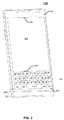
- FIG. 2 a perspective view of an example device 100 having a physical keyboard section 102 in a closed position and fully displaying a virtual keyboard 110 is shown.
- the main housing section 104 overlaps the physical keyboard section 102 and completely hides the physical keyboard.
- a full virtual keyboard 110 is displayed.
- the full virtual keyboard 110 has an upper boundary 202 and a lower boundary 204.
- the virtual keyboard 110 is positioned such that the lower boundary 204 of the virtual keyboard 110 is aligned along a bottom edge 206 of the touch-sensitive display 108.
- the virtual keyboard 110 may be positioned at other areas of the display 108 (e.g., in a divided screen, the upper boundary 202 aligned with an upper edge 208 of the display 108, etc.).
- the processor may turn off the touch-sensitive display 108 or place the device 100 in a low current usage state when a touch controller (not shown) for the touch-sensitive display 108 has not detected any touches on the display 108 for a predetermined period of time (i.e. a "time-out" period).
- a touch controller not shown
- the virtual keyboard 110 is not displayed during the time-out period until the processor detects a wake-up event (e.g., a touch on the touch-sensitive display 108, an incoming call, opening of the physical keyboard section 102, etc.). If the device 100 remains in the closed position upon wake-up, the full virtual keyboard 110 is displayed again.
- FIG. 3 shows a perspective view of an example device 100 having a physical keyboard section 102 in a partially open position and displaying a partial virtual keyboard 112 in accordance with an aspect of the present disclosure.
- the main housing section 104 partially overlaps the physical keyboard section 102, preventing access to the upper rows of physical keys 302 on the physical keyboard 106.
- the user may enter text by touching upper row keys displayed in the partial virtual keyboard 112 on the touch-sensitive display 108 or by pressing actual physical keys 302 of the exposed lower row keys of the physical keyboard 106.
- the virtual keyboard 112 is animated to disappear in correlation with the opening of the physical keyboard section 102.
- the virtual keyboard 112 is animated to appear in correlation with the opening of the physical keyboard section 102.
- the virtual keyboard 112 is animated to disappear by removing rows of keys or pixels from display beginning at the lower boundary 204 of the full virtual keyboard 100 and progressing through to the upper boundary 208 when the physical keyboard section 102 is moved from an open position to a closed position.
- the virtual keyboard 110 is animated to appear by adding rows of keys or pixels from display in an upper boundary 208 to lower boundary 204 manner when the physical keyboard section 102 is moved from a closed position to an open position.
- FIG. 4 is a perspective view of an example device 100 with the physical keyboard section 102 in a fully open position and not displaying a virtual keyboard in accordance with an aspect of the present disclosure.
- the physical keyboard section 102 is opened to the furthest extent permitted (i.e. the physical keyboard section 102 is prevented from further movement)
- all the physical keys 302 of the physical keyboard 106 are fully exposed and usable, thereby eliminating the need to display a virtual keyboard 110 on the touch-sensitive display 108.
- Such alternative virtual keyboards are not prohibited by implementation of the present disclosure.
- a capacitive touch detection sensor matrix 500 is shown.
- a capacitive touch sensor may be implemented using a film with conductive areas arranged in a pattern to create an X-Y matrix of isolated regions as shown in FIG. 5 .
- 5 rows 502a, 502b, 502c, 502d, 502e (referenced collectively as row 502) and 5 columns 504a, 504b, 504c, 504d, 504e (referenced collectively as 504) are shown for illustrative purposes only.
- rows 502 and columns 504 of sensor may be used to implement a capacitive touch detection sensor matrix 500.
- the capacitive touch detection sensor matrix 500 is located underneath the physical keyboard 106 and coupled to a touch controller (not shown) to create a physical capacitive touch keyboard to detect a "touch" upon the physical keys 302.
- a touch controller (not shown) to create a physical capacitive touch keyboard to detect a "touch" upon the physical keys 302.
- each column 504 of the matrix 500 is excited in succession by the touch controller and electrical charge is coupled into nearby rows 502.
- the touch controller scans the capacitive touch detection sensor matrix 500 to measure the coupled charge row-by-row.
- a baseline set of measurements is determined. Real systems include additional processing not included in this description but known to those skilled in the art. When one or more areas' current measurements change relative to the baseline, a "touch" is inferred by the touch controller.
- FIG. 6 is a time-lapsed illustration of detecting a single touch on a capacitive touch detection sensor matrix 500.
- Graph 600 represents the layout of capacitive touch detection sensor matrix 500 and shows the detected coupled charge over three instances of time.
- the touch controller is beginning to detect an area 602 of changed charge detection, indicated here as a light grey circular area with higher change of charge intensity at the center of the circle and diminishing towards the edges.
- the intensity of the coupled charge is shown as increasing as the grey tones become darker.
- the area 604 of increased change of charge has increased in size and intensity, and at time 3, a very distinct area 606 of high intensity change of charge is detected. This pattern of coupled charge is recognizable to the touch controller as a single touch occurring at position 606.
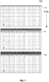
- FIG. 7 is a time-lapsed illustration of detecting closing of an overlapping main housing section 104 of a device 100 using a physical capacitive touch keyboard in accordance with an aspect of the present disclosure.
- Graph 700 represents the layout of capacitive touch detection sensor matrix 500 and shows the detected coupled charge over three instances of time.
- the touch controller is beginning to detect an area 702 of increased change of charge indicated here as a light grey area of one or more rows having higher change of charge intensity at the top of the capacitive touch detection sensor matrix 500 and diminishing as the rows are lower.
- the intensity of the coupled charge is shown as increasing as the grey tones become darker.
- the area 704 of increased charge has increased in size and intensity, and at time 6, a very distinct area 606 containing multiple rows of high intensity charge is detected.
- this pattern of coupled charge is recognizable to the touch controller as closing the physical capacitive touch keyboard in relation to the main housing unit 104.
- the processor can correlate the display of the virtual keyboard 110 in relation to the position and speed of the physical keyboard section 106 in a precise manner.
- the processor may still display the virtual keyboard in an animated fashion where the virtual keyboard appears in a scrolling manner with the uppermost rows of keys or pixels appearing first.
- the animation may be set to a completely display the full virtual keyboard 110 in a predetermined amount of time.
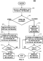
- FIG. 8 a flowchart illustrating an example process for detecting a change of position of a physical keyboard on a device and displaying a virtual keyboard in correlation with the position of the physical keyboard.
- the position detector detects movement of the physical keyboard section 102 in relation to the main housing unit 104. If the physical keyboard section 102 is open, at step 804, the processor begins displaying, at step 806, a partial virtual keyboard 112 on the touch-sensitive display 108 and correlates, at step 808, the appearance of the partial virtual keyboard 112 with the position of the physical keyboard section 102.
- the position detector is a capacitive touch detection sensor matrix 500
- the processor can easily correlate display of rows of the partial virtual keyboard 112 with a current position of the physical keyboard section 102.
- the processor will continue to correlate the display of the partial virtual keyboard 112 on the touch-sensitive display 108.
- the processor will display the full virtual keyboard 110 on the touch-sensitive display 108.
- the processor may cause the device 100 to enter a reduced power consumption mode and cease displaying the virtual keyboard.
- the processor begins removing, at step 814 the virtual keyboard 110 from the touch-sensitive display 108.
- the processor continues to correlate, at step 816, the removal of the virtual keyboard to the position of the physical keyboard section 102 as long as the physical keyboard section 102 is not in the fully open position. It should be noted that as the correlation is based on the current position of the physical keyboard section 102, it follows that the virtual display should be removed at the same speed in which the physical keyboard section 106 is moving.
- the virtual keyboard is no longer displayed, at step 820, on the touch-sensitive display 108.
- FIG. 9 further provides a state diagram reflecting changes in display of a virtual keyboard on a device in correlation with a position of a physical keyboard.
- state 902 when the physical keyboard section 102 is in a closed position, a full virtual keyboard is displayed.
- the processor Upon detection 904 of movement of the physical keyboard section 102 toward a fully open position, the processor begins displaying, at state 906, a partial virtual keyboard in correlation with the opening. From state 906, when the physical keyboard section 102 is moved 908 to a fully open position, at state 910, no virtual keyboard is displayed. From state 910, when movement toward a closed position is detected 912, the processor begins removing the virtual keyboard from display, at state 906.
- a full virtual keyboard is displayed on the touch-sensitive display.
- the animated virtual keyboard may not be completely engaged or disengaged if the physical keyboard section 102 does not reach a fully open or closed position. In other words, if the user is moving the physical keyboard section 102 back and forth, the animated virtual keyboard will scroll along with the physical keyboard section 102 in the direction and speed of movement.
- the processor may or may not display the virtual keyboard according to the context currently displayed on the touch-sensitive display 108.
- the virtual keyboard may not be displayed as a keyboard is typically not needed to navigate the homescreen.
- the device 100 may refrain from displaying the virtual keyboard in cases where the content shown on the display does not require interactive input (e.g., during media playback, etc.).
- an alternate virtual keyboard may be displayed comprising symbols not found on the physical keyboard 106 and relating to the context currently displayed, potentially including alternate key definitions to provide simplified navigation within the homescreen touch-sensitive icons or notifications for selection from the keyboard.
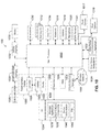
- wireless communication device 100 configured as a “wireless communication device,” referred to generally as “wireless communication device 100.”
- the wireless communication device 100 includes a number of components such as a main processor 1002 that controls the overall operation of the mobile device 10. Communication functions, including data and voice communications, are performed through at least one communication interface 1004.
- the communication interface 1004 receives messages from and sends messages to a wireless network 1005.
- the communication interface 1004 is configured in accordance with the Global System for Mobile Communication (GSM) and General Packet Radio Services (GPRS) standards, which is used worldwide.
- GSM Global System for Mobile Communication
- GPRS General Packet Radio Services
- the wireless link connecting the communication interface 1004 with the wireless network 1005 represents one or more different Radio Frequency (RF) channels, operating according to defined protocols specified for GSM/GPRS communications.
- RF Radio Frequency
- the main processor 1002 also interacts with additional subsystems such as a Random Access Memory (RAM) 1006, a flash memory 1008, a touch-sensitive display 1060, an auxiliary input/output (110) subsystem 1012, a data port 1014, a keyboard 1016 (physical, virtual, or both), a speaker 1018, a microphone 1020, a GPS receiver 1021, a front camera 1017, a rear camera 1019, short-range communications subsystem 1022, and other device subsystems 1024.
- RAM Random Access Memory
- the wireless communication device 100 can send and receive communication signals over the wireless network 1005 after required network registration or activation procedures have been completed.
- Network access is associated with a subscriber or user of the wireless communication device 100.
- the wireless communication device 100 may use a subscriber module component or "smart card" 1026, such as a Subscriber Identity Module (SIM), a Removable User Identity Module (RUIM) and a Universal Subscriber Identity Module (USIM).
- SIM Subscriber Identity Module
- RUIM Removable User Identity Module
- USB Universal Subscriber Identity Module
- a SIM/RUIM/USIM 1026 is to be inserted into a SIM/RUIM/USIM interface 1028 in order to communicate with a network.
- the wireless communication device 100 is typically a battery-powered device and includes a battery interface 1032 for receiving one or more rechargeable batteries 1030.
- the battery 1030 can be a smart battery with an embedded microprocessor.
- the battery interface 1032 is coupled to a regulator (not shown), which assists the battery 1030 in providing power to the wireless communication device 100.
- a regulator not shown
- future technologies such as micro fuel cells may provide the power to the wireless communication device 100.
- the wireless communication device 100 also includes an operating system 1034 and software components 1036 to 1042.
- the operating system 1034 and the software components 1036 to 1042, that are executed by the main processor 1002 are typically stored in a non-transitory persistent store such as the flash memory 1008, which may alternatively be a read-only memory (ROM) or similar storage element (not shown).
- ROM read-only memory
- portions of the operating system 1034 and the software components 1036 to 1042 such as specific device applications, or parts thereof, may be temporarily loaded into a volatile store such as the RAM 1006.
- Other software components can also be included, as is well known to those skilled in the art.
- the subset of software applications 1036 that control basic device operations, including data and voice communication applications, may be installed on the wireless communication device 100 during its manufacture.
- Software applications may include a message application 1038, a device state module 1040, and a Personal Information Manager (PIM) 1042.
- a message application 1038 can be any suitable software program that allows a user of the wireless communication device 100 to send and receive electronic messages, such as the email messaging application described herein, wherein messages are typically stored in the flash memory 1008 of the wireless communication device 100.
- a device state module 1040 provides persistence, i.e. the device state module 1040 ensures that important device data is stored in persistent memory, such as the flash memory 1008, so that the data is not lost when the mobile device 10 is turned off or loses power.
- a PIM 1042 includes functionality for organizing and managing data items of interest to the user, such as, but not limited to, e-mail, contacts, calendar events, and voice mails, and may interact with the wireless network 1005.
- software applications or components 1039 can also be installed on the wireless communication device 100. These software applications 1039 can be pre- installed applications (i.e. other than message application 1038) or third party applications, which are added after the manufacture of the wireless communication device 100. Examples of third party applications include games, calculators, utilities, etc.
- the additional applications 1039 can be loaded onto the wireless communication device 100 through at least one of the wireless network 1005, the auxiliary 1/0 subsystem 1012, the data port 1014, the short-range communications subsystem 1022, or any other suitable device subsystem 1024.
- the data port 1014 can be any suitable port that enables data communication between the wireless communication device 100 and another computing device.
- the data port 1014 can be a serial or a parallel port.
- the data port 1014 can be a Universal Serial Bus (USB) port that includes data lines for data transfer and a supply line that can provide a charging current to charge the battery 1030 of the wireless communication device 100.
- USB Universal Serial Bus
- received signals are output to the speaker 1018, and signals for transmission are generated by the microphone 1020.
- voice or audio signal output is accomplished primarily through the speaker 1018, the display 1050 can also be used to provide additional information such as the identity of a calling party, duration of a voice call, or other voice call related information.
- the touch-sensitive display 1060 may be any suitable touch-sensitive display, such as a capacitive, resistive, infrared, surface acoustic wave (SAW) touch-sensitive display, strain gauge, optical imaging, dispersive signal technology, acoustic pulse recognition, and so forth, as known in the art.
- the touch-sensitive display 1060 is a capacitive touch-sensitive display which includes a capacitive touch-sensitive overlay 1064.
- the overlay 1064 may be an assembly of multiple layers in a stack which may include, for example, a substrate, a ground shield layer, a barrier layer, one or more capacitive touch sensor layers separated by a substrate or other barrier, and a cover.
- the capacitive touch sensor layers may be any suitable material, such as patterned indium tin oxide (ITO).
- the display 1050 of the touch-sensitive display 1060 may include a display area in which information may be displayed, and a non-display area extending around the periphery of the display area. Information is not displayed in the non-display area, which is utilized to accommodate, for example, one or more of electronic traces or electrical connections, adhesives or other sealants, and protective coatings, around the edges of the display area.
- One or more touches may be detected by the touch-sensitive display 1060.
- the processor 1002 may determine attributes of the touch, including a location of a touch.
- Touch location data may include an area of contact or a single point of contact, such as a point at or near a center of the area of contact, known as the centroid.
- a signal is provided to the controller 1066 in response to detection of a touch.
- a touch may be detected from any suitable object, such as a finger, thumb, appendage, or other items, for example, a stylus, pen, or other pointer depending on the nature of the touch-sensitive display 1060.
- the location of the touch moves as the detected object moves during a touch.
- One or both of the controller 1066 and the processor 1002 may detect a touch by any suitable contact member on the touch- sensitive display 1060. Similarly, multiple simultaneous touches, are detected.
- a position detector 1090 is provided to detect the position of a physical keyboard 1060.
- the position detector 1090 may be a magnetic sensor, a mechanical switch, a touch controller coupled to a capacitive touch detection sensor matrix positioned underneath the physical keyboard 1060, or a combination thereof.
- aspects of the present disclosure may be embodied as a device or apparatus, system, method or computer program product. Accordingly, aspects of the present disclosure may take the form of an entirely hardware-based embodiment, an entirely software-based embodiment (including firmware, resident software, micro-code, etc.) or an embodiment combining software and hardware that may all generally be referred to herein as a "circuit,” “module” or “system.” Furthermore, aspects of the present disclosure may take the form of a computer program product embodied in one or more computer readable medium(s) having computer readable program code embodied thereon.
- a computer readable storage medium may be, for example, but not limited to, an electronic, magnetic, optical, electromagnetic, infrared, or semiconductor system, apparatus, or device, or any suitable combination of the foregoing. More specific examples (a non-exhaustive list) may include the following tangible media: an electrical connection having one or more wires, a portable computer diskette, a hard disk, a random access memory (RAM), a read-only memory (ROM), an erasable programmable read- only memory (EPROM or Flash memory), an optical fiber, a portable compact disc read- only memory (CD-ROM), an optical storage device, a magnetic storage device, or any suitable combination of the foregoing.
- Non-tangible or non-transitory media may include a propagated data signal with computer readable program code embodied therein, for example, in baseband or as part of a carrier wave. Such a propagated signal may take any of a variety of forms, including, but not limited to, electro-magnetic, optical, or any suitable combination thereof.
- Computer program code or instructions for carrying out operations for aspects of the present disclosure may be any combination of one or more programming languages, including an object oriented programming language and conventional procedural programming languages.
- the program code may execute on one or more devices such as a computer and/or server.
- each block of the block diagrams and/or flowchart illustration, and combinations of blocks in the block diagrams and/or flowchart illustration can be implemented wholly or partially by special purpose hardware-based systems that perform the specified functions or acts, or combinations of special purpose hardware and computer instructions.
- each block of the flowchart illustrations and/or block diagrams, and combinations of blocks in the flowchart illustrations and/or block diagrams can be implemented wholly or partially by computer program instructions.
- These computer program instructions may be provided to a processor of a general purpose computer, special purpose computer, or other programmable data processing apparatus to produce a machine, such that the instructions, which execute via the processor of the computer or other programmable data processing apparatus, create means for implementing the functions/acts specified in the flowchart and/or block diagram block or blocks.
Landscapes
- Engineering & Computer Science (AREA)
- Theoretical Computer Science (AREA)
- General Engineering & Computer Science (AREA)
- Physics & Mathematics (AREA)
- General Physics & Mathematics (AREA)
- Human Computer Interaction (AREA)
- Computer Hardware Design (AREA)
- Mathematical Physics (AREA)
- Input From Keyboards Or The Like (AREA)
Abstract
Description
- The present invention relates to device keyboard interfaces and more particularly to a movable assembly comprising a physical keyboard for use in a device and a method of detecting a position of the movable assembly and displaying a virtual keyboard based on the position.
- Small electronic devices, such as handheld wireless communication devices, may be constructed such that one or more assemblies may move in relation to one another. For example, in the context of wireless communication devices, certain form factors commonly known as "sliders" include a sliding physical keyboard which may be closed to hide the physical keyboard when the device is not currently in interactive use by a user. Detection of the position of the physical keypad may be used as a trigger for various functions such as wake the device, lock screen rotation, etc.
- Position detection may be achieved using additional electro-mechanical components, such as switches and magnets, which add additional cost to the device and consume valuable space within the limited constraints of the device. Additionally, these components may only detect an open or closed position and cannot define intermediate positions. In physical assemblies consisting of one or more moving pieces, there may be a need to detect and encode movement of individual pieces with greater granularity.
- An aspect of the present disclosure provides for a device, computer program product and method of operating the device. The device includes a housing section, a physical keyboard section, a position detector and a processor. The housing section carries a touch-sensitive display. The physical keyboard section is coupled to the housing section such that the physical keyboard is movable in a sliding direction relative to the housing section. The position detector determines a position of the physical keyboard section in relation to the housing section. The processor displays a graphical element on the touch-sensitive display when the position of the physical keyboard is closed and displays no graphical element when the position of the physical keyboard is open. In one aspect, the graphical element may be a virtual keyboard.
- In accordance with an aspect of the present disclosure, the position detector may be a magnetic sensor or a mechanical switch.
- In accordance with another aspect of the present disclosure, the processor displays the virtual keyboard on the touch-sensitive display as an animation displayed in a scrolling fashion correlated to the position of the physical keyboard section.
- In accordance with yet another aspect of the present disclosure, wherein the virtual keyboard comprises an upper boundary and a lower boundary, the virtual keyboard is removed from display in a lower boundary to an upper boundary manner when the physical keyboard is moved from an open position to a closed position. Likewise, the virtual keyboard is displayed in an upper boundary to a lower boundary manner when the physical keyboard is moved from a closed position to an open position.
- In accordance with one aspect of the present disclosure, wherein the physical keyboard section further comprises a capacitive touch detection sensor matrix, the position detector is a touch controller coupled to the capacitive touch detection sensor matrix. The touch controller may detect movement of the physical keyboard section by determining a baseline measurement by scanning the capacitive touch detection sensor matrix to measure coupled charge on a row-by-row basis, determining a current measurement by rescanning the capacitive touch detection sensor matrix to measure coupled charge on a row-by-row basis, comparing the current measurement the baseline measurement to determine a difference in coupled charge of at least one row, and determining a speed and direction of movement according to the difference in coupled charge.
- In accordance with yet another aspect of the present disclosure, the virtual keyboard is not displayed when the physical keyboard is in the closed position when the touch-sensitive display has detected no touches after expiration of a predetermined period of time.
- The accompanying drawings, which are incorporated in and constitute part of this specification, illustrate embodiments of the invention and together with the description, serve to explain the principles of the invention. The embodiments illustrated herein are presently preferred, it being understood, however, that the invention is not limited to the precise arrangements and instrumentalities shown, wherein:
-
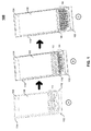
FIG. 1 is a pictorial illustration of an example process for detecting a position of a physical keyboard assembly in a device and correlating display of a virtual keyboard with the position of the physical keyboard in accordance with an aspect of the present disclosure; -
FIG. 2 is a perspective view of an example device having a physical keyboard in a closed position and fully displaying a virtual keyboard in accordance with an aspect of the present disclosure; -
FIG. 3 is a perspective view of an example device having a physical keyboard in a partially open position and partially displaying a virtual keyboard in accordance with an aspect of the present disclosure; -
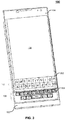
FIG. 4 is a perspective view of an example device having a physical keyboard in an open position and not displaying a virtual keyboard in accordance with an aspect of the present disclosure; -
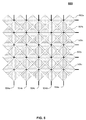
FIG. 5 is an example a capacitive touch detection sensor matrix used in conjunction with a physical keyboard to create a physical capacitive touch keyboard in accordance with an aspect of the present disclosure; -
FIG. 6 is a time-lapsed illustration of detecting a single touch on a physical capacitive touch keyboard; -
FIG. 7 is a time-lapsed illustration of detecting closing of an overlapping sliding housing section of a device using a physical capacitive touch keyboard in accordance with an aspect of the present disclosure; -
FIG. 8 is a flowchart illustrating an example process for detecting a change of position of a physical keyboard on a device and displaying a virtual keyboard in correlation with the position of the physical keyboard in accordance with an aspect of the present disclosure; -
FIG. 9 is a state diagram reflecting changes in display of a virtual keyboard on a device in correlation with a position of a physical keyboard in accordance with an aspect of the present disclosure; and -
FIG. 10 is a block diagram of an example device in accordance with an aspect of the present disclosure. - Referring now to
FIG. 1 , an illustration is provided showing an example procedure on adevice 100 for opening aphysical keyboard section 102 of thedevice 100 using a slider mechanism. Thedevice 100 may be a wireless communication device such as a cellular telephone, smart phone, personal data assistant (PDA), and the like. The slider mechanism allows thephysical keyboard section 102 to be coupled to amain housing section 104 such that thephysical keyboard section 102 moves in a sliding direction in relation to themain housing section 104 to reveal aphysical keyboard 106. Themain housing section 104 carries a touch-sensitive display 108 which may display a graphical element in correlation with the position of thephysical keyboard section 102. Thus, when thephysical keyboard section 102 is closed, the graphical element may be displayed and when thephysical keyboard section 102 is open, the graphical element may not be displayed, and vice versa. In one example, discussed in greater detail below, the graphical element is avirtual keyboard 110. In an alternate example, the main housing section may contain the physical keyboard and the slider mechanism may allow a display to move. - A position detector (not shown) detects the position of the
physical keyboard section 102 in relation to themain housing section 104. The position detector may be a magnetic sensor or mechanical switch located, inter alia, along thebottom edge 114 of themain housing section 114 or thetop edge 116 of thephysical keyboard section 102. Additionally, the position detector may be implemented as a capacitive touch detection sensor matrix (not shown) located underneath thephysical keyboard 106 and coupled to a touch controller (not shown). Alternatively, the position detector may be implemented as a capacitive touch detection sensor matrix located underneath the display. A magnetic sensor or a mechanical switch serve to function merely as an on/off detector, showing only that thephysical keyboard section 102 is opened or closed. However, the combination of capacitive touch detection sensor matrix and touch controller is much more sensitive and may be able to detect minute changes in position of thephysical keyboard section 102 which is discussed in greater detail below. In other examples, the position detector may be implemented using various other sensors that are able to detect the position of thephysical keyboard section 102, such as, but not limited to, one or more light sensors to detect the amount of light received at various locations along thephysical keyboard section 102. - When the
physical keyboard section 102 is in a closed position in relation to the main housing section 104 (i.e. position A andFIG. 2 ), thevirtual keyboard 110 may be fully displayed, allowing a user to type directly on the touch-sensitive display 108. When thephysical keyboard section 102 is in a fully open position in relation to themain housing section 104 where thephysical keyboard section 102 cannot be opened further (i.e. position C andFIG. 4 ), thevirtual keyboard 110 may not be displayed at all, allowing the user access to thephysical keyboard 106 for text entry, thereby providing a larger viewing area on the touch-sensitive display 108 combined with a physical keyboard for user input, such user input may be more accurate in comparison to a virtual keyboard. - In one example, while the
physical keyboard section 102 is in a partially open position (i.e. position BandFIG. 3 ) where certain upper keys on thephysical keyboard 106 are covered by themain housing section 104, a partialvirtual keyboard 112 is displayed on the touch-sensitive display 108 where the only keys displayed on the partialvirtual keyboard 112 correlate to the keys on thephysical keyboard 106 covered by themain housing section 104. As thephysical keyboard section 102 is opened further, additional keys disappear in the partialvirtual keyboard 112 as a scrolling animation which correlates the appearance of the partialvirtual keyboard 112 with the movement direction and speed of thephysical keyboard section 102. Depending upon the sensitivity of the position detector, the keys of the partialvirtual keyboard 112 may disappear according to a set height, such as a row of full-height keys, a row of one pixel height, or as partial rows of keys containing a certain number of pixel rows. In one example, the speed that the animation appears to scroll correlates to the speed at which thephysical keyboard section 102 is opened or closed. - Referring now to
FIG. 2 , a perspective view of anexample device 100 having aphysical keyboard section 102 in a closed position and fully displaying avirtual keyboard 110 is shown. In the closed position, themain housing section 104 overlaps thephysical keyboard section 102 and completely hides the physical keyboard. While in the closed position, a fullvirtual keyboard 110 is displayed. The fullvirtual keyboard 110 has anupper boundary 202 and alower boundary 204. In the example shown inFIG. 2 , thevirtual keyboard 110 is positioned such that thelower boundary 204 of thevirtual keyboard 110 is aligned along abottom edge 206 of the touch-sensitive display 108. In other examples, thevirtual keyboard 110 may be positioned at other areas of the display 108 (e.g., in a divided screen, theupper boundary 202 aligned with anupper edge 208 of thedisplay 108, etc.). - As most users store the
device 100 in a closed position when not in interactive use, in one example, the processor (not shown) may turn off the touch-sensitive display 108 or place thedevice 100 in a low current usage state when a touch controller (not shown) for the touch-sensitive display 108 has not detected any touches on thedisplay 108 for a predetermined period of time (i.e. a "time-out" period). In this case, thevirtual keyboard 110 is not displayed during the time-out period until the processor detects a wake-up event (e.g., a touch on the touch-sensitive display 108, an incoming call, opening of thephysical keyboard section 102, etc.). If thedevice 100 remains in the closed position upon wake-up, the fullvirtual keyboard 110 is displayed again. -
FIG. 3 shows a perspective view of anexample device 100 having aphysical keyboard section 102 in a partially open position and displaying a partialvirtual keyboard 112 in accordance with an aspect of the present disclosure. In this example, themain housing section 104 partially overlaps thephysical keyboard section 102, preventing access to the upper rows ofphysical keys 302 on thephysical keyboard 106. With a partially openedphysical keyboard section 102, the user may enter text by touching upper row keys displayed in the partialvirtual keyboard 112 on the touch-sensitive display 108 or by pressing actualphysical keys 302 of the exposed lower row keys of thephysical keyboard 106. - As the
physical keyboard section 102 is opened further, additional physical keys are exposed and thevirtual keyboard 112 is animated to disappear in correlation with the opening of thephysical keyboard section 102. Likewise, as thephysical keyboard section 102 is being closed, thevirtual keyboard 112 is animated to appear in correlation with the opening of thephysical keyboard section 102. In one example, thevirtual keyboard 112 is animated to disappear by removing rows of keys or pixels from display beginning at thelower boundary 204 of the fullvirtual keyboard 100 and progressing through to theupper boundary 208 when thephysical keyboard section 102 is moved from an open position to a closed position. Likewise, thevirtual keyboard 110 is animated to appear by adding rows of keys or pixels from display in anupper boundary 208 tolower boundary 204 manner when thephysical keyboard section 102 is moved from a closed position to an open position. -
FIG. 4 is a perspective view of anexample device 100 with thephysical keyboard section 102 in a fully open position and not displaying a virtual keyboard in accordance with an aspect of the present disclosure. When thephysical keyboard section 102 is opened to the furthest extent permitted (i.e. thephysical keyboard section 102 is prevented from further movement), all thephysical keys 302 of thephysical keyboard 106 are fully exposed and usable, thereby eliminating the need to display avirtual keyboard 110 on the touch-sensitive display 108. However, there may be instances, depending upon the context being displayed on the screen (e.g., a game, custom application, etc.) where it is desirable to display an alternate virtual keyboard comprising symbols not available on thephysical keyboard 106. Such alternative virtual keyboards are not prohibited by implementation of the present disclosure. - Referring now to
FIG. 5 , an example capacitive touchdetection sensor matrix 500 is shown. A capacitive touch sensor may be implemented using a film with conductive areas arranged in a pattern to create an X-Y matrix of isolated regions as shown inFIG. 5 . In this example matrix, 5rows columns detection sensor matrix 500. In one example, the capacitive touchdetection sensor matrix 500 is located underneath thephysical keyboard 106 and coupled to a touch controller (not shown) to create a physical capacitive touch keyboard to detect a "touch" upon thephysical keys 302. In a typical system, each column 504 of thematrix 500 is excited in succession by the touch controller and electrical charge is coupled into nearby rows 502. The touch controller scans the capacitive touchdetection sensor matrix 500 to measure the coupled charge row-by-row. During one complete scan of all columns 504 and rows 502, a baseline set of measurements is determined. Real systems include additional processing not included in this description but known to those skilled in the art. When one or more areas' current measurements change relative to the baseline, a "touch" is inferred by the touch controller. -
FIG. 6 is a time-lapsed illustration of detecting a single touch on a capacitive touchdetection sensor matrix 500.Graph 600 represents the layout of capacitive touchdetection sensor matrix 500 and shows the detected coupled charge over three instances of time. At time 1, the touch controller is beginning to detect anarea 602 of changed charge detection, indicated here as a light grey circular area with higher change of charge intensity at the center of the circle and diminishing towards the edges. Ingraph 600, the intensity of the coupled charge is shown as increasing as the grey tones become darker. At time 2, thearea 604 of increased change of charge has increased in size and intensity, and at time 3, a verydistinct area 606 of high intensity change of charge is detected. This pattern of coupled charge is recognizable to the touch controller as a single touch occurring atposition 606. - In contrast,
FIG. 7 is a time-lapsed illustration of detecting closing of an overlappingmain housing section 104 of adevice 100 using a physical capacitive touch keyboard in accordance with an aspect of the present disclosure.Graph 700 represents the layout of capacitive touchdetection sensor matrix 500 and shows the detected coupled charge over three instances of time. Attime 4, as the cover of themain housing section 104 is beginning to cover the physical capacitive touch keyboard, the touch controller is beginning to detect anarea 702 of increased change of charge indicated here as a light grey area of one or more rows having higher change of charge intensity at the top of the capacitive touchdetection sensor matrix 500 and diminishing as the rows are lower. Ingraph 700, as ingraph 600, the intensity of the coupled charge is shown as increasing as the grey tones become darker. At time 5, thearea 704 of increased charge has increased in size and intensity, and at time 6, a verydistinct area 606 containing multiple rows of high intensity charge is detected. As the increased charge area is along an increasing series of rows, this pattern of coupled charge is recognizable to the touch controller as closing the physical capacitive touch keyboard in relation to themain housing unit 104. Because the capacitive touchdetection sensor matrix 500 detects increased charge on a row-by-row basis, the processor can correlate the display of thevirtual keyboard 110 in relation to the position and speed of thephysical keyboard section 106 in a precise manner. - In other instances, for example, when the position detector is a magnetic sensor or a mechanical switch, although the exact positioning of the
physical keyboard section 102 may not be known, the processor may still display the virtual keyboard in an animated fashion where the virtual keyboard appears in a scrolling manner with the uppermost rows of keys or pixels appearing first. In such case, the animation may be set to a completely display the fullvirtual keyboard 110 in a predetermined amount of time. - Referring now to
FIG. 8 , a flowchart illustrating an example process for detecting a change of position of a physical keyboard on a device and displaying a virtual keyboard in correlation with the position of the physical keyboard. Beginning atstep 802, the position detector detects movement of thephysical keyboard section 102 in relation to themain housing unit 104. If thephysical keyboard section 102 is open, atstep 804, the processor begins displaying, atstep 806, a partialvirtual keyboard 112 on the touch-sensitive display 108 and correlates, atstep 808, the appearance of the partialvirtual keyboard 112 with the position of thephysical keyboard section 102. For example, when the position detector is a capacitive touchdetection sensor matrix 500, the processor can easily correlate display of rows of the partialvirtual keyboard 112 with a current position of thephysical keyboard section 102. - As long as the
physical keyboard section 102 is not fully closed, atstep 810, the processor will continue to correlate the display of the partialvirtual keyboard 112 on the touch-sensitive display 108. When thephysical keyboard section 102 is fully closed, atstep 810, the processor will display the fullvirtual keyboard 110 on the touch-sensitive display 108. Optionally, if a predetermined period of time lapses with detecting a touch on the touch-sensitive display, the processor may cause thedevice 100 to enter a reduced power consumption mode and cease displaying the virtual keyboard. - Returning to decision block 804, if the
physical keyboard section 102 is fully open, the processor begins removing, atstep 814 thevirtual keyboard 110 from the touch-sensitive display 108. The processor continues to correlate, atstep 816, the removal of the virtual keyboard to the position of thephysical keyboard section 102 as long as thephysical keyboard section 102 is not in the fully open position. It should be noted that as the correlation is based on the current position of thephysical keyboard section 102, it follows that the virtual display should be removed at the same speed in which thephysical keyboard section 106 is moving. When thephysical keyboard section 102 is fully open, atstep 818, the virtual keyboard is no longer displayed, atstep 820, on the touch-sensitive display 108. -
FIG. 9 further provides a state diagram reflecting changes in display of a virtual keyboard on a device in correlation with a position of a physical keyboard. Beginning atstate 902, when thephysical keyboard section 102 is in a closed position, a full virtual keyboard is displayed. Upondetection 904 of movement of thephysical keyboard section 102 toward a fully open position, the processor begins displaying, atstate 906, a partial virtual keyboard in correlation with the opening. Fromstate 906, when thephysical keyboard section 102 is moved 908 to a fully open position, atstate 910, no virtual keyboard is displayed. Fromstate 910, when movement toward a closed position is detected 912, the processor begins removing the virtual keyboard from display, atstate 906. Fromstate 906, when thephysical keyboard section 106 is moved 914 to a fully closed position, atstate 902, a full virtual keyboard is displayed on the touch-sensitive display. It should be noted that the animated virtual keyboard may not be completely engaged or disengaged if thephysical keyboard section 102 does not reach a fully open or closed position. In other words, if the user is moving thephysical keyboard section 102 back and forth, the animated virtual keyboard will scroll along with thephysical keyboard section 102 in the direction and speed of movement. - In an alternative embodiment, the processor may or may not display the virtual keyboard according to the context currently displayed on the touch-
sensitive display 108. For example, if the homescreen is displayed, the virtual keyboard may not be displayed as a keyboard is typically not needed to navigate the homescreen. Thedevice 100 may refrain from displaying the virtual keyboard in cases where the content shown on the display does not require interactive input (e.g., during media playback, etc.). In other instances, an alternate virtual keyboard may be displayed comprising symbols not found on thephysical keyboard 106 and relating to the context currently displayed, potentially including alternate key definitions to provide simplified navigation within the homescreen touch-sensitive icons or notifications for selection from the keyboard. - Referring to
FIG. 10 , to further aid in the understanding of theexample devices 100 described above, shown therein is a block diagram of an example configuration of a communication device configured as a "wireless communication device," referred to generally as "wireless communication device 100." Thewireless communication device 100 includes a number of components such as amain processor 1002 that controls the overall operation of themobile device 10. Communication functions, including data and voice communications, are performed through at least onecommunication interface 1004. Thecommunication interface 1004 receives messages from and sends messages to awireless network 1005. In this example of thewireless communication device 100, thecommunication interface 1004 is configured in accordance with the Global System for Mobile Communication (GSM) and General Packet Radio Services (GPRS) standards, which is used worldwide. Other communication configurations that are equally applicable are the 3G and 4G networks such as Enhanced Data-rates for Global Evolution (EDGE), Universal Mobile Telecommunications System (UMTS) and High-Speed Downlink Packet Access (HSDPA), Long Term Evolution (LTE), Worldwide Interoperability for Microwave Access (Wi-Max), etc. New standards are still being defined, but it is believed that they will have similarities to the network behavior described herein, and it will also be understood by persons skilled in the art that the examples described herein are intended to use any other suitable standards that are developed in the future. The wireless link connecting thecommunication interface 1004 with thewireless network 1005 represents one or more different Radio Frequency (RF) channels, operating according to defined protocols specified for GSM/GPRS communications. - The
main processor 1002 also interacts with additional subsystems such as a Random Access Memory (RAM) 1006, aflash memory 1008, a touch-sensitive display 1060, an auxiliary input/output (110)subsystem 1012, adata port 1014, a keyboard 1016 (physical, virtual, or both), aspeaker 1018, amicrophone 1020, aGPS receiver 1021, afront camera 1017, arear camera 1019, short-range communications subsystem 1022, andother device subsystems 1024. Some of the subsystems of thewireless communication device 100 perform communication-related functions, whereas other subsystems may provide "resident" or on-device functions. By way of example, the touch-sensitive display 1060 and thekeyboard 1016 may be used for both communication-related functions, such as entering a text message for transmission over thewireless network 1005, and device-resident functions such as a calculator or task list. - The
wireless communication device 100 can send and receive communication signals over thewireless network 1005 after required network registration or activation procedures have been completed. Network access is associated with a subscriber or user of thewireless communication device 100. To identify a subscriber, thewireless communication device 100 may use a subscriber module component or "smart card" 1026, such as a Subscriber Identity Module (SIM), a Removable User Identity Module (RUIM) and a Universal Subscriber Identity Module (USIM). In the example shown, a SIM/RUIM/USIM 1026 is to be inserted into a SIM/RUIM/USIM interface 1028 in order to communicate with a network. - The
wireless communication device 100 is typically a battery-powered device and includes abattery interface 1032 for receiving one or morerechargeable batteries 1030. In at least some examples, thebattery 1030 can be a smart battery with an embedded microprocessor. Thebattery interface 1032 is coupled to a regulator (not shown), which assists thebattery 1030 in providing power to thewireless communication device 100. Although current technology makes use of a battery, future technologies such as micro fuel cells may provide the power to thewireless communication device 100. - The
wireless communication device 100 also includes anoperating system 1034 andsoftware components 1036 to 1042. Theoperating system 1034 and thesoftware components 1036 to 1042, that are executed by themain processor 1002 are typically stored in a non-transitory persistent store such as theflash memory 1008, which may alternatively be a read-only memory (ROM) or similar storage element (not shown). Those skilled in the art will appreciate that portions of theoperating system 1034 and thesoftware components 1036 to 1042, such as specific device applications, or parts thereof, may be temporarily loaded into a volatile store such as theRAM 1006. Other software components can also be included, as is well known to those skilled in the art. - The subset of
software applications 1036 that control basic device operations, including data and voice communication applications, may be installed on thewireless communication device 100 during its manufacture. Software applications may include amessage application 1038, adevice state module 1040, and a Personal Information Manager (PIM) 1042. Amessage application 1038 can be any suitable software program that allows a user of thewireless communication device 100 to send and receive electronic messages, such as the email messaging application described herein, wherein messages are typically stored in theflash memory 1008 of thewireless communication device 100. Adevice state module 1040 provides persistence, i.e. thedevice state module 1040 ensures that important device data is stored in persistent memory, such as theflash memory 1008, so that the data is not lost when themobile device 10 is turned off or loses power. APIM 1042 includes functionality for organizing and managing data items of interest to the user, such as, but not limited to, e-mail, contacts, calendar events, and voice mails, and may interact with thewireless network 1005. - Other types of software applications or
components 1039 can also be installed on thewireless communication device 100. Thesesoftware applications 1039 can be pre- installed applications (i.e. other than message application 1038) or third party applications, which are added after the manufacture of thewireless communication device 100. Examples of third party applications include games, calculators, utilities, etc. - The
additional applications 1039 can be loaded onto thewireless communication device 100 through at least one of thewireless network 1005, the auxiliary 1/0subsystem 1012, thedata port 1014, the short-range communications subsystem 1022, or any othersuitable device subsystem 1024. - The
data port 1014 can be any suitable port that enables data communication between thewireless communication device 100 and another computing device. Thedata port 1014 can be a serial or a parallel port. In some instances, thedata port 1014 can be a Universal Serial Bus (USB) port that includes data lines for data transfer and a supply line that can provide a charging current to charge thebattery 1030 of thewireless communication device 100. - For voice communications, received signals are output to the
speaker 1018, and signals for transmission are generated by themicrophone 1020. Although voice or audio signal output is accomplished primarily through thespeaker 1018, thedisplay 1050 can also be used to provide additional information such as the identity of a calling party, duration of a voice call, or other voice call related information. - The touch-
sensitive display 1060 may be any suitable touch-sensitive display, such as a capacitive, resistive, infrared, surface acoustic wave (SAW) touch-sensitive display, strain gauge, optical imaging, dispersive signal technology, acoustic pulse recognition, and so forth, as known in the art. In the presently described example, the touch-sensitive display 1060 is a capacitive touch-sensitive display which includes a capacitive touch-sensitive overlay 1064. Theoverlay 1064 may be an assembly of multiple layers in a stack which may include, for example, a substrate, a ground shield layer, a barrier layer, one or more capacitive touch sensor layers separated by a substrate or other barrier, and a cover. The capacitive touch sensor layers may be any suitable material, such as patterned indium tin oxide (ITO). - The
display 1050 of the touch-sensitive display 1060 may include a display area in which information may be displayed, and a non-display area extending around the periphery of the display area. Information is not displayed in the non-display area, which is utilized to accommodate, for example, one or more of electronic traces or electrical connections, adhesives or other sealants, and protective coatings, around the edges of the display area. - One or more touches, also known as touch contacts or touch events, may be detected by the touch-
sensitive display 1060. Theprocessor 1002 may determine attributes of the touch, including a location of a touch. Touch location data may include an area of contact or a single point of contact, such as a point at or near a center of the area of contact, known as the centroid. A signal is provided to thecontroller 1066 in response to detection of a touch. A touch may be detected from any suitable object, such as a finger, thumb, appendage, or other items, for example, a stylus, pen, or other pointer depending on the nature of the touch-sensitive display 1060. The location of the touch moves as the detected object moves during a touch. One or both of thecontroller 1066 and theprocessor 1002 may detect a touch by any suitable contact member on the touch-sensitive display 1060. Similarly, multiple simultaneous touches, are detected. - In some examples, a
position detector 1090 is provided to detect the position of aphysical keyboard 1060. Theposition detector 1090 may be a magnetic sensor, a mechanical switch, a touch controller coupled to a capacitive touch detection sensor matrix positioned underneath thephysical keyboard 1060, or a combination thereof. - Aspects of the present disclosure may be embodied as a device or apparatus, system, method or computer program product. Accordingly, aspects of the present disclosure may take the form of an entirely hardware-based embodiment, an entirely software-based embodiment (including firmware, resident software, micro-code, etc.) or an embodiment combining software and hardware that may all generally be referred to herein as a "circuit," "module" or "system." Furthermore, aspects of the present disclosure may take the form of a computer program product embodied in one or more computer readable medium(s) having computer readable program code embodied thereon. A computer readable storage medium may be, for example, but not limited to, an electronic, magnetic, optical, electromagnetic, infrared, or semiconductor system, apparatus, or device, or any suitable combination of the foregoing. More specific examples (a non-exhaustive list) may include the following tangible media: an electrical connection having one or more wires, a portable computer diskette, a hard disk, a random access memory (RAM), a read-only memory (ROM), an erasable programmable read- only memory (EPROM or Flash memory), an optical fiber, a portable compact disc read- only memory (CD-ROM), an optical storage device, a magnetic storage device, or any suitable combination of the foregoing. Non-tangible or non-transitory media may include a propagated data signal with computer readable program code embodied therein, for example, in baseband or as part of a carrier wave. Such a propagated signal may take any of a variety of forms, including, but not limited to, electro-magnetic, optical, or any suitable combination thereof. Computer program code or instructions for carrying out operations for aspects of the present disclosure may be any combination of one or more programming languages, including an object oriented programming language and conventional procedural programming languages. The program code may execute on one or more devices such as a computer and/or server.
- Aspects of the present disclosure have been described above with reference to flowchart illustrations and/or block diagrams of methods, apparatus (systems) and computer program products according to embodiments of the disclosure. In this regard, the flowchart and block diagrams in the figures illustrate the architecture, functionality, and operation of possible implementations of systems, methods and computer program products according to various embodiments. However it should also be noted that, in some alternative implementations, the functions noted in the block may occur out of the order noted in the figures. For example, two blocks shown in succession may, in fact, be executed substantially concurrently, or the blocks may sometimes be executed in the reverse order, depending upon the functionality involved. It will also be noted that each block of the block diagrams and/or flowchart illustration, and combinations of blocks in the block diagrams and/or flowchart illustration, can be implemented wholly or partially by special purpose hardware-based systems that perform the specified functions or acts, or combinations of special purpose hardware and computer instructions. Furthermore it also will be understood that each block of the flowchart illustrations and/or block diagrams, and combinations of blocks in the flowchart illustrations and/or block diagrams, can be implemented wholly or partially by computer program instructions. These computer program instructions may be provided to a processor of a general purpose computer, special purpose computer, or other programmable data processing apparatus to produce a machine, such that the instructions, which execute via the processor of the computer or other programmable data processing apparatus, create means for implementing the functions/acts specified in the flowchart and/or block diagram block or blocks.
- Finally, the terminology used herein is for the purpose of describing particular embodiments only and is not intended to be limiting. That is, the description of the present disclosure has been presented for purposes of illustration and description, but is not intended to be exhaustive or limited to the form disclosed. Many modifications and variations will be apparent without departing from the scope of the disclosure defined in the appended claims.
Claims (11)
- A device comprising:a housing section comprising a touch-sensitive display;a physical keyboard section coupled to the housing section such that the physical keyboard is movable in a sliding direction relative to the housing;a position detector that determines a position of the physical keyboard section in relation to the housing section; anda processor that displays a graphical element on the touch-sensitive display when the position of the physical keyboard is closed and displays no graphical element when the position of the physical keyboard is open.
- The device of claim 1, wherein the position detector is one or more of a magnetic sensor, a mechanical switch and a capacitive sensor.
- The device of claim 1, wherein the graphical element is a virtual keyboard.
- The device of claim 3, wherein the processor displays the virtual keyboard on the touch-sensitive display as an animation displayed in a scrolling fashion correlated with the position of the physical keyboard section.
- The device of claim 4, wherein the virtual keyboard comprises an upper boundary and a lower boundary, the virtual keyboard is removed from display in a lower boundary to an upper boundary manner when the physical keyboard is moved from an open position to a closed position, and the virtual keyboard is displayed in an upper boundary to a lower boundary manner when the physical keyboard is moved from a closed position to an open position.
- The device of claim 4, wherein the physical keyboard section further comprises a capacitive touch detection sensor matrix, the position detector is a touch controller coupled to the capacitive touch detection sensor matrix.
- The device of claim 6, wherein the touch controller detects movement of the physical keyboard section by:determining a baseline measurement by scanning the capacitive touch detection sensor matrix to measure coupled charge on a row-by-row basis;determining a current measurement by rescanning the capacitive touch detection sensor matrix to measure coupled charge on a row-by-row basis;comparing the current measurement the baseline measurement to determine a difference in coupled charge of at least one row; anddetermining a speed and direction of movement according to the difference in coupled charge.
- The device of claim 3, wherein the virtual keyboard is not displayed when the physical keyboard is in the closed position when the touch-sensitive display has detected no touches after expiration of a predetermined period of time.
- A method of operating a device having a housing section carrying a touch- sensitive display and a physical keyboard movable in a sliding direction relative to the housing section, the method comprising:determining, by a position detector, a position of the physical keyboard section in relation to the housing section;displaying, by a processor, a graphical element on the touch-sensitive display when the position of the physical keyboard is closed; anddisplaying, by a processor, no graphical element on the touch-sensitive display when the position of the physical keyboard is open.
- A computer program product for operating a device having a housing section carrying a touch-sensitive display and a physical keyboard movable in a sliding direction relative to the housing, the computer program product comprising:a non-transitory computer readable storage medium having computer readable program code embodied therewith, the computer readable program code comprising:computer readable program code for performing the steps of claim 9.
- The computer program product of claim 10, wherein the position detector is one or more of a magnetic sensor, a mechanical switch, a capacitive sensor and a touch controller coupled to a capacitive touch detection sensor matrix carried by the physical keyboard section.
Applications Claiming Priority (1)
| Application Number | Priority Date | Filing Date | Title |
|---|---|---|---|
| US14/874,344 US9746937B2 (en) | 2015-10-02 | 2015-10-02 | Method and apparatus for movable assembly position sensing and virtual keyboard display |
Publications (2)
| Publication Number | Publication Date |
|---|---|
| EP3151088A1 true EP3151088A1 (en) | 2017-04-05 |
| EP3151088B1 EP3151088B1 (en) | 2019-11-06 |
Family
ID=56896361
Family Applications (1)
| Application Number | Title | Priority Date | Filing Date |
|---|---|---|---|
| EP16187074.6A Active EP3151088B1 (en) | 2015-10-02 | 2016-09-02 | Method and apparatus for movable assembly position sensing and virtual keyboard display |
Country Status (2)
| Country | Link |
|---|---|
| US (1) | US9746937B2 (en) |
| EP (1) | EP3151088B1 (en) |
Families Citing this family (12)
| Publication number | Priority date | Publication date | Assignee | Title |
|---|---|---|---|---|
| KR20170003906A (en) * | 2014-05-09 | 2017-01-10 | 삼성전자주식회사 | Terminal and method for displaying caller information |
| US10254900B2 (en) * | 2016-02-18 | 2019-04-09 | Tufts University | Drifting keyboard |
| US11029843B2 (en) * | 2016-09-16 | 2021-06-08 | Tactual Labs Co. | Touch sensitive keyboard |
| US10599259B2 (en) * | 2017-11-20 | 2020-03-24 | Google Llc | Virtual reality / augmented reality handheld controller sensing |
| JP6467732B1 (en) * | 2018-02-23 | 2019-02-13 | 靖彦 佐竹 | Keyboard input electronic device input method |
| US10712832B2 (en) * | 2018-11-15 | 2020-07-14 | Dell Products, L.P. | On-screen keyboard detection for multi-form factor information handling systems (IHSs) |
| CN109542174B (en) * | 2018-11-30 | 2020-07-31 | Oppo广东移动通信有限公司 | Method and device for correcting sliding of sliding component |
| US11893163B2 (en) * | 2020-12-11 | 2024-02-06 | Dell Products L.P. | Information handling system virtual and physical keyboard position coordination |
| US12038795B2 (en) | 2020-12-11 | 2024-07-16 | Dell Products L.P. | Information handling system visual presentation with audio vector based information |
| US11662712B2 (en) | 2020-12-11 | 2023-05-30 | Dell Products L.P. | Information handling system housing cover inflatable seal |
| CN115037976A (en) * | 2021-03-03 | 2022-09-09 | Oppo广东移动通信有限公司 | Display method, terminal and storage medium |
| CN115129225A (en) * | 2021-03-26 | 2022-09-30 | 北京小米移动软件有限公司 | Keyboard toolbar display method, keyboard toolbar display device and storage medium |
Citations (7)
| Publication number | Priority date | Publication date | Assignee | Title |
|---|---|---|---|---|
| US20060287015A1 (en) * | 2005-06-15 | 2006-12-21 | Sony Ericsson Mobile Communications Ab | Closed mode user interface for wireless communication devices |
| EP2046003A1 (en) * | 2007-10-01 | 2009-04-08 | LG Electronics Inc. | Mobile terminal and controlling method thereof |
| US20100099463A1 (en) * | 2008-10-16 | 2010-04-22 | Jun-Hee Kim | Mobile terminal having touch sensor-equipped input device and control method thereof |
| EP2228976A1 (en) * | 2007-12-27 | 2010-09-15 | NEC Corporation | Portable terminal device |
| US20130009858A1 (en) * | 2011-07-08 | 2013-01-10 | Lacey Jon-David Kenneth | Systems and methods for locking an electronic device |
| US20130127778A1 (en) * | 2011-11-22 | 2013-05-23 | Sony Mobile Communications Ab | Key device and electronic equipment |
| US20140225629A1 (en) * | 2011-09-29 | 2014-08-14 | Sony Corporation | Information processing apparatus, method, program, and recording medium |
Family Cites Families (3)
| Publication number | Priority date | Publication date | Assignee | Title |
|---|---|---|---|---|
| US8265717B2 (en) * | 2009-06-26 | 2012-09-11 | Motorola Mobility Llc | Implementation of touchpad on rear surface of single-axis hinged device |
| US9778706B2 (en) * | 2012-02-24 | 2017-10-03 | Blackberry Limited | Peekable user interface on a portable electronic device |
| US8847979B2 (en) * | 2012-06-08 | 2014-09-30 | Samuel G. Smith | Peek mode and graphical user interface (GUI) experience |
-
2015
- 2015-10-02 US US14/874,344 patent/US9746937B2/en active Active
-
2016
- 2016-09-02 EP EP16187074.6A patent/EP3151088B1/en active Active
Patent Citations (7)
| Publication number | Priority date | Publication date | Assignee | Title |
|---|---|---|---|---|
| US20060287015A1 (en) * | 2005-06-15 | 2006-12-21 | Sony Ericsson Mobile Communications Ab | Closed mode user interface for wireless communication devices |
| EP2046003A1 (en) * | 2007-10-01 | 2009-04-08 | LG Electronics Inc. | Mobile terminal and controlling method thereof |
| EP2228976A1 (en) * | 2007-12-27 | 2010-09-15 | NEC Corporation | Portable terminal device |
| US20100099463A1 (en) * | 2008-10-16 | 2010-04-22 | Jun-Hee Kim | Mobile terminal having touch sensor-equipped input device and control method thereof |
| US20130009858A1 (en) * | 2011-07-08 | 2013-01-10 | Lacey Jon-David Kenneth | Systems and methods for locking an electronic device |
| US20140225629A1 (en) * | 2011-09-29 | 2014-08-14 | Sony Corporation | Information processing apparatus, method, program, and recording medium |
| US20130127778A1 (en) * | 2011-11-22 | 2013-05-23 | Sony Mobile Communications Ab | Key device and electronic equipment |
Also Published As
| Publication number | Publication date |
|---|---|
| US9746937B2 (en) | 2017-08-29 |
| US20170097689A1 (en) | 2017-04-06 |
| EP3151088B1 (en) | 2019-11-06 |
Similar Documents
| Publication | Publication Date | Title |
|---|---|---|
| EP3151088B1 (en) | Method and apparatus for movable assembly position sensing and virtual keyboard display | |
| US8744530B2 (en) | Portable electronic device and method of controlling same | |
| US9778706B2 (en) | Peekable user interface on a portable electronic device | |
| CN107479737B (en) | Portable electronic device and control method thereof | |
| US8121652B2 (en) | Portable electronic device including touchscreen and method of controlling the portable electronic device | |
| US9043718B2 (en) | System and method for applying a text prediction algorithm to a virtual keyboard | |
| US8619041B2 (en) | Portable electronic device and method of controlling same | |
| US20100110017A1 (en) | Portable electronic device and method of controlling same | |
| US20090172531A1 (en) | Method of displaying menu items and related touch screen device | |
| US20140181758A1 (en) | System and Method for Displaying Characters Using Gestures | |
| CA2686769C (en) | Portable electronic device and method of controlling same | |
| EP2104027B1 (en) | Electronic device including touch sensitive input surface and method of determining user-selected input | |
| WO2009115871A1 (en) | Two way touch-sensitive display | |
| CA2806801C (en) | Peekable user interface on a portable electronic device | |
| CA2679142C (en) | Portable electronic device and method of controlling same | |
| US20100321302A1 (en) | System and method for non-roman text input | |
| EP2184669A1 (en) | Portable electronic device and method of controlling same | |
| WO2013190857A1 (en) | Processing device, sensitivity adjustment method and program | |
| CA2706055C (en) | System and method for applying a text prediction algorithm to a virtual keyboard | |
| KR20100132864A (en) | Mobile terminal and its gesture input processing method | |
| EP2199898B1 (en) | Portable electronic device including touchscreen and method of controlling the portable electronic device | |
| EP2746920A1 (en) | System and method for displaying characters using gestures |
Legal Events
| Date | Code | Title | Description |
|---|---|---|---|
| PUAI | Public reference made under article 153(3) epc to a published international application that has entered the european phase |
Free format text: ORIGINAL CODE: 0009012 |
|
| STAA | Information on the status of an ep patent application or granted ep patent |
Free format text: STATUS: THE APPLICATION HAS BEEN PUBLISHED |
|
| AK | Designated contracting states |
Kind code of ref document: A1 Designated state(s): AL AT BE BG CH CY CZ DE DK EE ES FI FR GB GR HR HU IE IS IT LI LT LU LV MC MK MT NL NO PL PT RO RS SE SI SK SM TR |
|
| AX | Request for extension of the european patent |
Extension state: BA ME |
|
| STAA | Information on the status of an ep patent application or granted ep patent |
Free format text: STATUS: REQUEST FOR EXAMINATION WAS MADE |
|
| 17P | Request for examination filed |
Effective date: 20171004 |
|
| RBV | Designated contracting states (corrected) |
Designated state(s): AL AT BE BG CH CY CZ DE DK EE ES FI FR GB GR HR HU IE IS IT LI LT LU LV MC MK MT NL NO PL PT RO RS SE SI SK SM TR |
|
| STAA | Information on the status of an ep patent application or granted ep patent |
Free format text: STATUS: EXAMINATION IS IN PROGRESS |
|
| 17Q | First examination report despatched |
Effective date: 20180119 |
|
| RIC1 | Information provided on ipc code assigned before grant |
Ipc: G06F 1/16 20060101ALI20190401BHEP Ipc: G06F 3/0488 20130101ALI20190401BHEP Ipc: G06F 3/044 20060101ALI20190401BHEP Ipc: G06F 3/02 20060101AFI20190401BHEP Ipc: G06F 3/0485 20130101ALI20190401BHEP |
|
| GRAP | Despatch of communication of intention to grant a patent |
Free format text: ORIGINAL CODE: EPIDOSNIGR1 |
|
| STAA | Information on the status of an ep patent application or granted ep patent |
Free format text: STATUS: GRANT OF PATENT IS INTENDED |
|
| INTG | Intention to grant announced |
Effective date: 20190513 |
|
| GRAS | Grant fee paid |
Free format text: ORIGINAL CODE: EPIDOSNIGR3 |
|
| GRAA | (expected) grant |
Free format text: ORIGINAL CODE: 0009210 |
|
| STAA | Information on the status of an ep patent application or granted ep patent |
Free format text: STATUS: THE PATENT HAS BEEN GRANTED |
|
| AK | Designated contracting states |
Kind code of ref document: B1 Designated state(s): AL AT BE BG CH CY CZ DE DK EE ES FI FR GB GR HR HU IE IS IT LI LT LU LV MC MK MT NL NO PL PT RO RS SE SI SK SM TR |
|
| REG | Reference to a national code |
Ref country code: GB Ref legal event code: FG4D |
|
| REG | Reference to a national code |
Ref country code: CH Ref legal event code: EP Ref country code: AT Ref legal event code: REF Ref document number: 1199660 Country of ref document: AT Kind code of ref document: T Effective date: 20191115 |
|
| REG | Reference to a national code |
Ref country code: IE Ref legal event code: FG4D |
|
| REG | Reference to a national code |
Ref country code: DE Ref legal event code: R096 Ref document number: 602016023649 Country of ref document: DE |
|
| REG | Reference to a national code |
Ref country code: NL Ref legal event code: MP Effective date: 20191106 |
|
| REG | Reference to a national code |
Ref country code: LT Ref legal event code: MG4D |
|
| PG25 | Lapsed in a contracting state [announced via postgrant information from national office to epo] |
Ref country code: BG Free format text: LAPSE BECAUSE OF FAILURE TO SUBMIT A TRANSLATION OF THE DESCRIPTION OR TO PAY THE FEE WITHIN THE PRESCRIBED TIME-LIMIT Effective date: 20200206 Ref country code: NO Free format text: LAPSE BECAUSE OF FAILURE TO SUBMIT A TRANSLATION OF THE DESCRIPTION OR TO PAY THE FEE WITHIN THE PRESCRIBED TIME-LIMIT Effective date: 20200206 Ref country code: FI Free format text: LAPSE BECAUSE OF FAILURE TO SUBMIT A TRANSLATION OF THE DESCRIPTION OR TO PAY THE FEE WITHIN THE PRESCRIBED TIME-LIMIT Effective date: 20191106 Ref country code: PT Free format text: LAPSE BECAUSE OF FAILURE TO SUBMIT A TRANSLATION OF THE DESCRIPTION OR TO PAY THE FEE WITHIN THE PRESCRIBED TIME-LIMIT Effective date: 20200306 Ref country code: LV Free format text: LAPSE BECAUSE OF FAILURE TO SUBMIT A TRANSLATION OF THE DESCRIPTION OR TO PAY THE FEE WITHIN THE PRESCRIBED TIME-LIMIT Effective date: 20191106 Ref country code: SE Free format text: LAPSE BECAUSE OF FAILURE TO SUBMIT A TRANSLATION OF THE DESCRIPTION OR TO PAY THE FEE WITHIN THE PRESCRIBED TIME-LIMIT Effective date: 20191106 Ref country code: NL Free format text: LAPSE BECAUSE OF FAILURE TO SUBMIT A TRANSLATION OF THE DESCRIPTION OR TO PAY THE FEE WITHIN THE PRESCRIBED TIME-LIMIT Effective date: 20191106 Ref country code: LT Free format text: LAPSE BECAUSE OF FAILURE TO SUBMIT A TRANSLATION OF THE DESCRIPTION OR TO PAY THE FEE WITHIN THE PRESCRIBED TIME-LIMIT Effective date: 20191106 Ref country code: PL Free format text: LAPSE BECAUSE OF FAILURE TO SUBMIT A TRANSLATION OF THE DESCRIPTION OR TO PAY THE FEE WITHIN THE PRESCRIBED TIME-LIMIT Effective date: 20191106 Ref country code: GR Free format text: LAPSE BECAUSE OF FAILURE TO SUBMIT A TRANSLATION OF THE DESCRIPTION OR TO PAY THE FEE WITHIN THE PRESCRIBED TIME-LIMIT Effective date: 20200207 |
|
| PG25 | Lapsed in a contracting state [announced via postgrant information from national office to epo] |
Ref country code: HR Free format text: LAPSE BECAUSE OF FAILURE TO SUBMIT A TRANSLATION OF THE DESCRIPTION OR TO PAY THE FEE WITHIN THE PRESCRIBED TIME-LIMIT Effective date: 20191106 Ref country code: IS Free format text: LAPSE BECAUSE OF FAILURE TO SUBMIT A TRANSLATION OF THE DESCRIPTION OR TO PAY THE FEE WITHIN THE PRESCRIBED TIME-LIMIT Effective date: 20200306 Ref country code: RS Free format text: LAPSE BECAUSE OF FAILURE TO SUBMIT A TRANSLATION OF THE DESCRIPTION OR TO PAY THE FEE WITHIN THE PRESCRIBED TIME-LIMIT Effective date: 20191106 |
|
| PG25 | Lapsed in a contracting state [announced via postgrant information from national office to epo] |
Ref country code: AL Free format text: LAPSE BECAUSE OF FAILURE TO SUBMIT A TRANSLATION OF THE DESCRIPTION OR TO PAY THE FEE WITHIN THE PRESCRIBED TIME-LIMIT Effective date: 20191106 |
|
| PG25 | Lapsed in a contracting state [announced via postgrant information from national office to epo] |
Ref country code: CZ Free format text: LAPSE BECAUSE OF FAILURE TO SUBMIT A TRANSLATION OF THE DESCRIPTION OR TO PAY THE FEE WITHIN THE PRESCRIBED TIME-LIMIT Effective date: 20191106 Ref country code: ES Free format text: LAPSE BECAUSE OF FAILURE TO SUBMIT A TRANSLATION OF THE DESCRIPTION OR TO PAY THE FEE WITHIN THE PRESCRIBED TIME-LIMIT Effective date: 20191106 Ref country code: RO Free format text: LAPSE BECAUSE OF FAILURE TO SUBMIT A TRANSLATION OF THE DESCRIPTION OR TO PAY THE FEE WITHIN THE PRESCRIBED TIME-LIMIT Effective date: 20191106 Ref country code: EE Free format text: LAPSE BECAUSE OF FAILURE TO SUBMIT A TRANSLATION OF THE DESCRIPTION OR TO PAY THE FEE WITHIN THE PRESCRIBED TIME-LIMIT Effective date: 20191106 Ref country code: DK Free format text: LAPSE BECAUSE OF FAILURE TO SUBMIT A TRANSLATION OF THE DESCRIPTION OR TO PAY THE FEE WITHIN THE PRESCRIBED TIME-LIMIT Effective date: 20191106 |
|
| REG | Reference to a national code |
Ref country code: DE Ref legal event code: R097 Ref document number: 602016023649 Country of ref document: DE |
|
| REG | Reference to a national code |
Ref country code: AT Ref legal event code: MK05 Ref document number: 1199660 Country of ref document: AT Kind code of ref document: T Effective date: 20191106 |
|
| PG25 | Lapsed in a contracting state [announced via postgrant information from national office to epo] |
Ref country code: SM Free format text: LAPSE BECAUSE OF FAILURE TO SUBMIT A TRANSLATION OF THE DESCRIPTION OR TO PAY THE FEE WITHIN THE PRESCRIBED TIME-LIMIT Effective date: 20191106 Ref country code: SK Free format text: LAPSE BECAUSE OF FAILURE TO SUBMIT A TRANSLATION OF THE DESCRIPTION OR TO PAY THE FEE WITHIN THE PRESCRIBED TIME-LIMIT Effective date: 20191106 |
|
| PLBE | No opposition filed within time limit |
Free format text: ORIGINAL CODE: 0009261 |
|
| STAA | Information on the status of an ep patent application or granted ep patent |
Free format text: STATUS: NO OPPOSITION FILED WITHIN TIME LIMIT |
|
| 26N | No opposition filed |
Effective date: 20200807 |
|
| PG25 | Lapsed in a contracting state [announced via postgrant information from national office to epo] |
Ref country code: AT Free format text: LAPSE BECAUSE OF FAILURE TO SUBMIT A TRANSLATION OF THE DESCRIPTION OR TO PAY THE FEE WITHIN THE PRESCRIBED TIME-LIMIT Effective date: 20191106 Ref country code: SI Free format text: LAPSE BECAUSE OF FAILURE TO SUBMIT A TRANSLATION OF THE DESCRIPTION OR TO PAY THE FEE WITHIN THE PRESCRIBED TIME-LIMIT Effective date: 20191106 |
|
| PG25 | Lapsed in a contracting state [announced via postgrant information from national office to epo] |
Ref country code: IT Free format text: LAPSE BECAUSE OF FAILURE TO SUBMIT A TRANSLATION OF THE DESCRIPTION OR TO PAY THE FEE WITHIN THE PRESCRIBED TIME-LIMIT Effective date: 20191106 |
|
| PG25 | Lapsed in a contracting state [announced via postgrant information from national office to epo] |
Ref country code: MC Free format text: LAPSE BECAUSE OF FAILURE TO SUBMIT A TRANSLATION OF THE DESCRIPTION OR TO PAY THE FEE WITHIN THE PRESCRIBED TIME-LIMIT Effective date: 20191106 |
|
| REG | Reference to a national code |
Ref country code: CH Ref legal event code: PL |
|
| REG | Reference to a national code |
Ref country code: BE Ref legal event code: MM Effective date: 20200930 |
|
| PG25 | Lapsed in a contracting state [announced via postgrant information from national office to epo] |
Ref country code: LU Free format text: LAPSE BECAUSE OF NON-PAYMENT OF DUE FEES Effective date: 20200902 |
|
| PG25 | Lapsed in a contracting state [announced via postgrant information from national office to epo] |
Ref country code: CH Free format text: LAPSE BECAUSE OF NON-PAYMENT OF DUE FEES Effective date: 20200930 Ref country code: BE Free format text: LAPSE BECAUSE OF NON-PAYMENT OF DUE FEES Effective date: 20200930 Ref country code: IE Free format text: LAPSE BECAUSE OF NON-PAYMENT OF DUE FEES Effective date: 20200902 Ref country code: LI Free format text: LAPSE BECAUSE OF NON-PAYMENT OF DUE FEES Effective date: 20200930 |
|
| PG25 | Lapsed in a contracting state [announced via postgrant information from national office to epo] |
Ref country code: TR Free format text: LAPSE BECAUSE OF FAILURE TO SUBMIT A TRANSLATION OF THE DESCRIPTION OR TO PAY THE FEE WITHIN THE PRESCRIBED TIME-LIMIT Effective date: 20191106 Ref country code: MT Free format text: LAPSE BECAUSE OF FAILURE TO SUBMIT A TRANSLATION OF THE DESCRIPTION OR TO PAY THE FEE WITHIN THE PRESCRIBED TIME-LIMIT Effective date: 20191106 Ref country code: CY Free format text: LAPSE BECAUSE OF FAILURE TO SUBMIT A TRANSLATION OF THE DESCRIPTION OR TO PAY THE FEE WITHIN THE PRESCRIBED TIME-LIMIT Effective date: 20191106 |
|
| PG25 | Lapsed in a contracting state [announced via postgrant information from national office to epo] |
Ref country code: MK Free format text: LAPSE BECAUSE OF FAILURE TO SUBMIT A TRANSLATION OF THE DESCRIPTION OR TO PAY THE FEE WITHIN THE PRESCRIBED TIME-LIMIT Effective date: 20191106 |
|
| REG | Reference to a national code |
Ref country code: DE Ref legal event code: R081 Ref document number: 602016023649 Country of ref document: DE Owner name: MALIKIE INNOVATIONS LTD., IE Free format text: FORMER OWNER: BLACKBERRY LIMITED, WATERLOO, ONTARIO, CA |
|
| REG | Reference to a national code |
Ref country code: GB Ref legal event code: 732E Free format text: REGISTERED BETWEEN 20240620 AND 20240627 |
|
| PGFP | Annual fee paid to national office [announced via postgrant information from national office to epo] |
Ref country code: DE Payment date: 20250926 Year of fee payment: 10 |
|
| PGFP | Annual fee paid to national office [announced via postgrant information from national office to epo] |
Ref country code: GB Payment date: 20250923 Year of fee payment: 10 |
|
| PGFP | Annual fee paid to national office [announced via postgrant information from national office to epo] |
Ref country code: FR Payment date: 20250925 Year of fee payment: 10 |