EP3150971A1 - Control sensor assembly for an agricultural harvester - Google Patents
Control sensor assembly for an agricultural harvester Download PDFInfo
- Publication number
- EP3150971A1 EP3150971A1 EP16191258.9A EP16191258A EP3150971A1 EP 3150971 A1 EP3150971 A1 EP 3150971A1 EP 16191258 A EP16191258 A EP 16191258A EP 3150971 A1 EP3150971 A1 EP 3150971A1
- Authority
- EP
- European Patent Office
- Prior art keywords
- sensor assembly
- bushing
- control sensor
- header
- mount
- Prior art date
- Legal status (The legal status is an assumption and is not a legal conclusion. Google has not performed a legal analysis and makes no representation as to the accuracy of the status listed.)
- Granted
Links
Images






Classifications
-
- A—HUMAN NECESSITIES
- A01—AGRICULTURE; FORESTRY; ANIMAL HUSBANDRY; HUNTING; TRAPPING; FISHING
- A01D—HARVESTING; MOWING
- A01D34/00—Mowers; Mowing apparatus of harvesters
- A01D34/006—Control or measuring arrangements
- A01D34/008—Control or measuring arrangements for automated or remotely controlled operation
-
- G—PHYSICS
- G01—MEASURING; TESTING
- G01D—MEASURING NOT SPECIALLY ADAPTED FOR A SPECIFIC VARIABLE; ARRANGEMENTS FOR MEASURING TWO OR MORE VARIABLES NOT COVERED IN A SINGLE OTHER SUBCLASS; TARIFF METERING APPARATUS; MEASURING OR TESTING NOT OTHERWISE PROVIDED FOR
- G01D11/00—Component parts of measuring arrangements not specially adapted for a specific variable
- G01D11/30—Supports specially adapted for an instrument; Supports specially adapted for a set of instruments
-
- G—PHYSICS
- G01—MEASURING; TESTING
- G01D—MEASURING NOT SPECIALLY ADAPTED FOR A SPECIFIC VARIABLE; ARRANGEMENTS FOR MEASURING TWO OR MORE VARIABLES NOT COVERED IN A SINGLE OTHER SUBCLASS; TARIFF METERING APPARATUS; MEASURING OR TESTING NOT OTHERWISE PROVIDED FOR
- G01D5/00—Mechanical means for transferring the output of a sensing member; Means for converting the output of a sensing member to another variable where the form or nature of the sensing member does not constrain the means for converting; Transducers not specially adapted for a specific variable
- G01D5/12—Mechanical means for transferring the output of a sensing member; Means for converting the output of a sensing member to another variable where the form or nature of the sensing member does not constrain the means for converting; Transducers not specially adapted for a specific variable using electric or magnetic means
- G01D5/14—Mechanical means for transferring the output of a sensing member; Means for converting the output of a sensing member to another variable where the form or nature of the sensing member does not constrain the means for converting; Transducers not specially adapted for a specific variable using electric or magnetic means influencing the magnitude of a current or voltage
- G01D5/142—Mechanical means for transferring the output of a sensing member; Means for converting the output of a sensing member to another variable where the form or nature of the sensing member does not constrain the means for converting; Transducers not specially adapted for a specific variable using electric or magnetic means influencing the magnitude of a current or voltage using Hall-effect devices
- G01D5/145—Mechanical means for transferring the output of a sensing member; Means for converting the output of a sensing member to another variable where the form or nature of the sensing member does not constrain the means for converting; Transducers not specially adapted for a specific variable using electric or magnetic means influencing the magnitude of a current or voltage using Hall-effect devices influenced by the relative movement between the Hall device and magnetic fields
-
- G—PHYSICS
- G01—MEASURING; TESTING
- G01R—MEASURING ELECTRIC VARIABLES; MEASURING MAGNETIC VARIABLES
- G01R33/00—Arrangements or instruments for measuring magnetic variables
- G01R33/02—Measuring direction or magnitude of magnetic fields or magnetic flux
- G01R33/06—Measuring direction or magnitude of magnetic fields or magnetic flux using galvano-magnetic devices
-
- A—HUMAN NECESSITIES
- A01—AGRICULTURE; FORESTRY; ANIMAL HUSBANDRY; HUNTING; TRAPPING; FISHING
- A01D—HARVESTING; MOWING
- A01D2101/00—Lawn-mowers
Definitions
- the subject application relates generally to a control sensor assembly for an agricultural harvester.
- the subject application provides an improved mount for the control sensor assembly that utilizes a single mount to perform multiple functions.
- a header at the front of a harvester cuts ripened crops from the field.
- the header is attached to the front of the harvester and includes mechanisms, for example, for cutting crops, gathering crops and depositing crops into a feederhouse.
- the objective of the agricultural harvester is to gather as much crop material as possible when traveling across the field. This can become increasingly difficult as the ground contour can vary.
- header height control systems are utilized to raise, lower and tilt the header in order to maximize the harvester's crop yield.
- a header height control system utilizes a control sensor assembly to accurately detect the contour of the ground for changes in landscape i.e., its position relative to the ground as it travels over uneven terrain.
- Conventional control sensor assemblies require the use of multiple sensors and parts which consequently requires a larger number of steps and complexity in the installation process. During installation, operators have to ensure that the control sensor assembly is properly oriented for connection to the header height control system. If assembly and installation is done incorrectly, this could lead to increased delays and maintenance costs, improper operation of the harvester, economic loss, as well as damage to components of the agricultural harvester.
- the subject application provides a control sensor assembly for an agricultural harvester.
- the control sensor assembly comprises a linkage, a bushing, a mount and a sensor.
- the linkage is for connection to a header height control system.
- the bushing includes a first end connected to the linkage and a second end housing a magnet.
- the mount includes a body having a through hole extending from a first surface to a second surface opposite the first surface for receiving the bushing and a first rotational stop about the first surface and adjacent the through hole.
- the sensor is mounted to the mount and spaced from the second end of the bushing.
- the subject application provides a header of an agricultural harvester.
- the header comprises a frame, a linkage and a control sensor assembly mounted to the frame.
- the control sensor assembly includes a bushing, a mount and a sensor.
- the bushing includes a first end connected to the linkage and a second end housing a magnet.
- the mount includes a body having a through hole extending from a first surface to a second surface opposite the first surface for receiving the bushing and a first rotational stop about the first surface and adjacent the through hole.
- the sensor is mounted to the mount and spaced from the second end of the bushing.
- the subject application provides a mount for mounting a sensor to a header of an agricultural harvester.
- the mount comprises a body and first and second spaced apart guide surfaces.
- the body includes a counterbore and a through hole extending through the counterbore from a first surface of the body to a second surface of the body opposite the first surface.
- the body further includes an anterior surface adjacent the counterbore and extending substantially transverse to the first surface.
- the first and second spaced apart guide surfaces extend from the first surface.
- Each guide surface is positioned adjacent a lateral side of the counterbore and the first guide surface includes an engaging surface at an angle relative to an engaging surface of the second guide surface.
- the first and second guide surfaces each have a mounting surface and an opening through which a fastener is passable for securing the mount to the header.
- the mounting surface is substantially parallel to and spaced from the first surface for engaging the header.
- the subject application provides a unique mount for a non-contact header height control sensor that uses one piece to perform multiple functions.
- the main block will control shaft end-play, act as a rotational stop, serve as the sensor mount, and mount the entire system to a machine that is using header height control (HHC).
- HHC header height control
- a non-contact sensor is a sensor in which the magnet is a separate piece from the sensor body itself unlike a one piece sensor in which everything is contained within the sensor body.
- the non-contact sensor needs to maintain a specified air gap between the magnet and the sensor body for proper functionality.
- a system is needed to control the end play of the magnet that is attached to the rotating shaft and consistently hold the sensor body at the appropriate location.
- the rotational motion needs a bearing surface to allow free rotation of the shaft.
- the system also needs a rotational stop so that during assembly it cannot be assembled incorrectly.
- the system is also simpler than what is currently used. It has fewer parts and would be used multiple times in comparison to once per header.
- header height control systems consist of a laser formed piece with two machined hubs welded to it, two bushings pressed into each hub, and two snap rings.
- the assembly is for one side of the machine and would have a mirror image on the opposite side.
- the parts in the disclosed system of the subject application would be a machined block and a plastic bearing surface.
- the subject application's assembly can be used multiple times e.g., four times, on the header whereas the current system has a left and right and is only used once per head.
- the main block of the system is machined so that from the face of one side to the other side, the distance will be consistent allowing the air gap between the magnet and the sensor body to be precisely controlled. Additionally, the machined rotational stops will automatically be formed into the block. The rotational stops will help with the installation by forcing the installer to properly orient the block with respect to the side of the machine, since this single block will be able to be used in multiple locations on the machine.
- the plastic bearing surface will also hold multiple functions. On one side of the plastic part, there will be a machined spot for the magnet to be attached to. The opposite end will have another machine feature that will act as a receiver that will accept a driver feature on the header height control linkage. This all can be assembled first and then assembled to the machine. The machine will act as the stop that does not allow the magnet to get farther away from the sensor.
- the resultant advantages of the subject application include having fewer parts that need to be maintained.
- the auger and draper head use different parts that perform the same function along with needing a left and right portion which means four separate assembly part numbers, not including sub parts that go into the assembly.
- the subject application would allow for the same assembly parts to be used on both heads for the left and right sides, reducing four separate assembly part numbers to one.
- the subject application's system would require fewer processes to make the assembly than currently is required.
- Conventional header height control systems require a laser process, forming process, machining process, welding process and painting while the subject application would only need a machining process or a molding process (for a plastic mount) to manufacture the mount.
- the built in stops will require the assembler to only assemble the subject application in the correct way.
- the current system is mounted using two bolts which would allow the operator to incorrectly assemble it if they were not paying attention.
- the subject application provides an improved mount for a non-contact header height control sensor that performs multiple functions including controlling shaft end-play, acting as a rotational stop, serving as a sensor mount, and mounting the entire system to the machine that is using header height control.
- the resultant advantages of such a mount are that one single part is performing multiple tasks while controlling the air gap needed for the two piece sensor.
- FIG. 1 illustrates several features of a frame of a header of an agricultural harvester according to the subject application.
- the header will be described e.g., as a header with a flexible cutter bar assembly, but can alternatively be any other header having a height control sensor.
- the header includes mechanisms for cutting crops, gathering crops and delivering crops to the agricultural harvester and is positioned relative to a ground surface upon which the agricultural harvester travels.
- FIG. 1 there is shown a control sensor assembly 12 mounted to a side of a frame 10 of a header which can be attached to the front or anterior end of a combine or similar agricultural harvester (not shown).
- the frame 10 serves generally as a chassis for the header for supporting the various components of the header which are attached thereto.
- the header can include, among other components, a cutter bar.
- Such components of the header are known and therefore a detailed description of their structure, function and operation is not necessary for a complete understanding of the subject application.
- headers applicable to the subject application are disclosed in U.S. Patent Nos. 7,950,212 ; 7,222,474 ; and 4,414,793 .
- the cutter bar severs crops as the header of the agricultural harvester travels over the field.
- the crops are then conveyed towards other downstream components of the agricultural harvester, e.g., auger or feeder (not shown).
- the cutter bar is designed to have flexibility in order to accommodate and conform generally to changing ground contours at different locations of the field.
- a reliable ground sensor is required to serve as indicators of ground contour changes to adjust the height position of the header and its components.
- a control sensor assembly 12 is configured and operable according to the teachings of the subject application, for following and sensing ground contour changes and outputting signals representative thereof to a header height control system 11 ( FIG. 10 ) of an agricultural harvester.
- the control sensor assembly 12 allows the header height control system 11 to raise or lower the header as required for maintaining the cutter bar at a desired level above the ground.
- the control sensor assembly 12 includes a linkage 14, a bushing 16, a mount 18 and a sensor 20.
- the linkage 14 connects the control sensor assembly 12 to the header height control system 11 in a conventional, well-known manner in the art.
- the linkage 14 has a proximal end with an aperture configured to receive a shaft 22 connecting the linkage to the bushing 16.
- the shaft 22 has a circular shaped first end corresponding to the aperture of the linkage 14 and an angular shaped second end e.g., a parallel piped shaft, opposite the first end.
- the angular shape of the second end corresponds to a slot 24 in the bushing 16 for connecting the linkage 14 and bushing 16.
- the linkage 14 also has a distal end with an aperture for adjustably connecting the linkage to the header height control system.
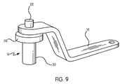
- FIG. 9 shows an isolated perspective view of the shaft 22 connecting the linkage 14 to the bushing 16.
- the bushing 16 includes a first end connected to the linkage 14 and a second end housing a magnet 26.
- the bushing 16 is preferably configured as a flanged bushing with a flange member 28 and a stem 30 extending from the flange member.
- the stem 30 is preferably configured as an elongated cylindrical member.
- the flange member 28 has a diameter larger than that of the stem 30.
- the flange member 28 at the first end of the bushing 16 can include a slot 24 for receiving the angular end of the shaft 22 in order to connect the proximal end of the linkage to the bushing 16.
- the slot 24 and the angular end of the shaft 22 can be configured with any other shape suitable for its intended purpose, such as a shaft having a longitudinal cross section of a square, triangle, and the like.
- the linkage 14 and the bushing 16 can alternatively be connected with suitable fasteners, e.g. pins, screws, bolts, and the like.
- the second end of the bushing 16 includes a cavity 25 for housing a magnet 26 of a non-contact magnetic sensor, as further discussed below.
- the cavity 25 about a second end of the bushing 16 is preferably shaped to correspondingly receive and fixedly hold the magnet 26.
- the magnet 26 is fixedly mounted to the bushing 16 allowing it to rotate as the bushing rotates.
- the rotational movement of the magnet 26 with respect to the sensor 20 results in an output signal representative of a positional relationship between the header and the ground.
- the mount 18 includes a body 32 and spaced apart first and second rotational stops 34, 36.
- the mount 18 is configured as a block for operatively connecting to a flexible cutter bar system.
- the block can be appropriately modified such that the control sensor assembly 12 is applicable to different types of headers, e.g., corn header, auger, draper and the like.
- the body 32 includes a counterbore 38 and a through hole 40 extending through the counterbore 38.
- the through hole 40 extends from a first surface 42 of the body to a second surface 44 of the body opposite the first surface and has a central longitudinal axis substantially transverse to a plane of the first surface 42.
- the body further includes an anterior surface 46 adjacent the counterbore 38 and extending substantially transverse to the first surface 42.
- the through hole 40 is configured to receive the second end of the bushing 16.
- a seal 48 e.g., an oil seal
- the seal 48 is shaped to slidably fit around the cylindrical shape of the stem 30 of the bushing.
- the seal 48 surrounds the stem 30 and sits adjacent the flange member 28.
- the seal 48 seats within the counterbore 38 and prevents dirt and moisture from entering.
- the body is sized so as to have a longitudinal length of the through hole 40 to be greater than a longitudinal length of the stem 30 of the bushing 16 when the bushing is seated on the block.
- the bushing 16 is sized to have a longitudinal length such that the second end of the bushing is spaced from the second surface 44 when fully seated on the block. This way, the distal end of the bushing housing the magnet is spaced from the second surface thereby creating an air gap between the magnet and the sensor mounted to the second surface.
- the through hole 40 extends to the second surface 44 of the body.
- the sensor 20 is mounted onto the second surface 44.
- the second surface 44 of the body comprises a recess 50 for at least partially receiving a complementary seal 52, e.g., an O-ring, ( FIG. 4 ) for preventing dirt and moisture from entering and causing the control sensor assembly 12 to malfunction.
- the seal 52 is positioned within the recess 50 as shown in FIGS. 5A and 5B .
- the second surface 44 can include a pair of openings 54 for mounting the sensor 20 onto the mount 18 with suitable fasteners, e.g. pins, screws, bolts and the like.
- first and second spaced apart rotational stops 34, 36 extend from the first surface 42.
- Each rotational stop 34, 36 is positioned adjacent a lateral side of the counterbore 38 and the first rotational stop 34 includes an engaging surface 56 at an angle ⁇ of about 80 to 100 degrees relative to an engaging surface 58 of the second rotational stop 36.
- the rotational stops can alternatively be configured with an angle ⁇ more or less than 80 to 100 degrees or any angle between 80 and 100 degrees.
- the first rotational stop 34 and second rotational stop 36 are respectively spaced from each other about the first surface 42 of the mount 18.
- the engaging surfaces 56, 58 of the respective first and second rotational stops 34, 36 define a space or range of motion the linkage 14 can pivot relative the mount 18. While the first and second rotational stops 34, 36 are referred to as rotational stops, they do not necessarily have to, but can, function as rotational stops. Instead, the first and second rotational stops 34, 36 can be guide surfaces collectively forming a one way guide slot to aid in properly assembling the linkage 14 to the mount 18 in a proper orientation. In other words, the first and second rotational stops 34, 36 collectively form a guide slot having a posterior back wall and a tapered opening about its anterior end. The guide slot is preferably configured to have a posterior end complementary in shape to receive the bushing 16 and an open anterior end through which the linkage 14 will reside in with enough play so that the inner side walls of the guide slot do not engage the linkage 14 during general operation.
- the through hole 40 has a diameter slightly larger than the diameter of the stem 30 of the bushing 16 such that the bushing 16 is rotatable therein.
- the linkage 14 connected to the second end of the bushing 16 rotates.
- the linkage 14 has a limited range of motion as defined by its connections with the header height control system and is generally restricted to movement between the first and second rotational stops 34, 36.
- the mount 18 includes a curved section 60 extending between the first and second rotational stops 34, 36.
- the curved section 60 is sized and configured to receive the flange member 28 of the bushing 16. Specifically, it is shaped to be complementary to the shape of the flange member 28 of the bushing 16.
- the rotational stops 34, 36 each have a mounting surface 62 substantially parallel to and spaced from the first surface 42 for engaging with the header and an opening 64 through which a fastener is passable for securing the mount 18 to the frame of a header.
- the mount 18 can be connected to the frame 10 with any suitable fasteners, e.g. pins, screws, bolts and the like.
- the mount 18 and the type of fasteners used can be adjusted to accommodate different headers, e.g., a corn header, draper, auger and the like.
- the mounting surface 62 of the rotational stops 34, 36 directly engages the frame 10 and the linkage 14 is positioned completely between the first and second rotational stops 34, 36.
- the proximal end of the linkage 14 is also positioned completely between the mounting surface 62 of the first surface 42.
- the mount 18 further includes lateral side surfaces 66 extending substantially transverse to the first surface 42. Further, each of the first and second rotational stops 34, 36 include lateral side surfaces substantially parallel to and in line with respective lateral side surfaces 66 of the body.
- the senor 20 is mounted to the mount 18 and spaced from the second end of the bushing 16. As discussed above, the second surface 44 of the body of the mount 18 contains a pair of openings 54 for mounting the sensor 20 onto the mount 18.
- the sensor 20 is preferably a non-contact magnetic sensor, such as a Hall effect sensor.
- the control sensor assembly 12 needs to properly maintain the air gap between the sensor 20 and the magnet 26.
- the sensor 20 disclosed in the subject application does not have connected moving parts. Thus, the sensor 20 disclosed in the subject application does not result in wear that can result in damage to the sensor.
- the control sensor assembly 12 can be fully assembled prior to installation to the frame 10.
- the through hole 40 on the mount 18 extends between the first surface 42 and the second surface 44.
- the stem 30 of the bushing 16 is received within the through hole 40 about the first surface 42.
- the proximal end of the linkage 14 is connected to the flange member 28 of the bushing 16.
- the sensor 20 is mounted about the second surface 44 of the mount 18 such that the magnet 26 on the bushing 16 is spaced from the sensor 20 defining an air gap therebetween.
- the control sensor assembly 12 is secured to the frame 10 of the header.
- the rotational stops 34, 36 assist in proper placement of the mount 18 when securing the mount onto the frame 10.
- FIG. 10 there is shown a side view of a frame 10 of a header.
- the control sensor assembly 12 (not shown) is connected to the header height control system 11.
- the linkage 14 connects the control sensor assembly 12 to the header height control system 11.
- the header of the agricultural harvester travels along the field.
- the cutter bar assembly 76 moves up and down causing the sensor arm 68 to move up and down.
- the sensor arm 68 is configured to rest on the cutter bar assembly 76.
- the sensor arm 68 is also welded to a sensor rod 70. Thus, when the sensor arm moves up or down, the sensor rod 70 rotates as well.
- the rotation of the sensor rod 70 causes a linking member 72 to rotate accordingly.
- the linking member 72 is coupled to the linkage 14 of the control sensor assembly 12 by a connector 74.
- the rotational motion of the linking member causes the linkage 14 to rotate.
- the bushing 16 and the magnet 26 rotate.
- the magnet 26 is fixedly mounted to the bushing 16 allowing it to rotate as the bushing rotates.
- the rotation of the magnet results in the sensor 20 outputting a signal representative of a positional relationship between the header and the ground.
- the sensor 20 configured as a Hall effect sensor produces a voltage representative of the positional relationship between the header and the ground.
- the header height control system 11 and its components discussed above cause movement of the linkage 14 and magnet 26 of the control sensor assembly 12.
- the sensor 20 produces an output voltage representative of the positional relationship between the header and the ground. The output voltage is transmitted to a computer of the agricultural harvester.
- a draper header can have four control sensor assemblies, two for tilt and two for height.
- an auger head can have four control sensor assemblies, while a corn header can have between two and four or more control sensor assemblies.
Landscapes
- Physics & Mathematics (AREA)
- General Physics & Mathematics (AREA)
- Life Sciences & Earth Sciences (AREA)
- Environmental Sciences (AREA)
- Condensed Matter Physics & Semiconductors (AREA)
- Guiding Agricultural Machines (AREA)
- Harvester Elements (AREA)
Description
- The subject application relates generally to a control sensor assembly for an agricultural harvester. In particular, the subject application provides an improved mount for the control sensor assembly that utilizes a single mount to perform multiple functions.
- During a harvesting operation, a header at the front of a harvester cuts ripened crops from the field. The header is attached to the front of the harvester and includes mechanisms, for example, for cutting crops, gathering crops and depositing crops into a feederhouse. The objective of the agricultural harvester is to gather as much crop material as possible when traveling across the field. This can become increasingly difficult as the ground contour can vary. As a result, header height control systems are utilized to raise, lower and tilt the header in order to maximize the harvester's crop yield.
- Generally, a header height control system utilizes a control sensor assembly to accurately detect the contour of the ground for changes in landscape i.e., its position relative to the ground as it travels over uneven terrain. Conventional control sensor assemblies require the use of multiple sensors and parts which consequently requires a larger number of steps and complexity in the installation process. During installation, operators have to ensure that the control sensor assembly is properly oriented for connection to the header height control system. If assembly and installation is done incorrectly, this could lead to increased delays and maintenance costs, improper operation of the harvester, economic loss, as well as damage to components of the agricultural harvester.
- Therefore, there is still a need for an improved mount for a control sensor assembly that reduces potential for human error and performs multiple functions with less assembly parts and requires fewer steps to install the assembly. The subject application addresses the foregoing issues of conventional control sensor assemblies.
- In accordance with an aspect, the subject application provides a control sensor assembly for an agricultural harvester. The control sensor assembly comprises a linkage, a bushing, a mount and a sensor. The linkage is for connection to a header height control system. The bushing includes a first end connected to the linkage and a second end housing a magnet. The mount includes a body having a through hole extending from a first surface to a second surface opposite the first surface for receiving the bushing and a first rotational stop about the first surface and adjacent the through hole. The sensor is mounted to the mount and spaced from the second end of the bushing.
- In accordance with another aspect, the subject application provides a header of an agricultural harvester. The header comprises a frame, a linkage and a control sensor assembly mounted to the frame. The control sensor assembly includes a bushing, a mount and a sensor. The bushing includes a first end connected to the linkage and a second end housing a magnet. The mount includes a body having a through hole extending from a first surface to a second surface opposite the first surface for receiving the bushing and a first rotational stop about the first surface and adjacent the through hole. The sensor is mounted to the mount and spaced from the second end of the bushing.
- In accordance with yet another aspect, the subject application provides a mount for mounting a sensor to a header of an agricultural harvester. The mount comprises a body and first and second spaced apart guide surfaces. The body includes a counterbore and a through hole extending through the counterbore from a first surface of the body to a second surface of the body opposite the first surface. The body further includes an anterior surface adjacent the counterbore and extending substantially transverse to the first surface. The first and second spaced apart guide surfaces extend from the first surface. Each guide surface is positioned adjacent a lateral side of the counterbore and the first guide surface includes an engaging surface at an angle relative to an engaging surface of the second guide surface. The first and second guide surfaces each have a mounting surface and an opening through which a fastener is passable for securing the mount to the header. The mounting surface is substantially parallel to and spaced from the first surface for engaging the header.
- The subject application provides a unique mount for a non-contact header height control sensor that uses one piece to perform multiple functions. The main block will control shaft end-play, act as a rotational stop, serve as the sensor mount, and mount the entire system to a machine that is using header height control (HHC). A non-contact sensor is a sensor in which the magnet is a separate piece from the sensor body itself unlike a one piece sensor in which everything is contained within the sensor body. The non-contact sensor needs to maintain a specified air gap between the magnet and the sensor body for proper functionality. Thus, a system is needed to control the end play of the magnet that is attached to the rotating shaft and consistently hold the sensor body at the appropriate location. Along with the end play, the rotational motion needs a bearing surface to allow free rotation of the shaft. The system also needs a rotational stop so that during assembly it cannot be assembled incorrectly. The system is also simpler than what is currently used. It has fewer parts and would be used multiple times in comparison to once per header.
- Conventional header height control systems consist of a laser formed piece with two machined hubs welded to it, two bushings pressed into each hub, and two snap rings. The assembly is for one side of the machine and would have a mirror image on the opposite side. The parts in the disclosed system of the subject application would be a machined block and a plastic bearing surface. The subject application's assembly can be used multiple times e.g., four times, on the header whereas the current system has a left and right and is only used once per head.
- In the subject application, the main block of the system is machined so that from the face of one side to the other side, the distance will be consistent allowing the air gap between the magnet and the sensor body to be precisely controlled. Additionally, the machined rotational stops will automatically be formed into the block. The rotational stops will help with the installation by forcing the installer to properly orient the block with respect to the side of the machine, since this single block will be able to be used in multiple locations on the machine. The plastic bearing surface will also hold multiple functions. On one side of the plastic part, there will be a machined spot for the magnet to be attached to. The opposite end will have another machine feature that will act as a receiver that will accept a driver feature on the header height control linkage. This all can be assembled first and then assembled to the machine. The machine will act as the stop that does not allow the magnet to get farther away from the sensor.
- In addition to controlling the air gap, the resultant advantages of the subject application include having fewer parts that need to be maintained. In conventional header height control systems, the auger and draper head use different parts that perform the same function along with needing a left and right portion which means four separate assembly part numbers, not including sub parts that go into the assembly. The subject application would allow for the same assembly parts to be used on both heads for the left and right sides, reducing four separate assembly part numbers to one. The subject application's system would require fewer processes to make the assembly than currently is required. Conventional header height control systems require a laser process, forming process, machining process, welding process and painting while the subject application would only need a machining process or a molding process (for a plastic mount) to manufacture the mount. The built in stops will require the assembler to only assemble the subject application in the correct way. The current system is mounted using two bolts which would allow the operator to incorrectly assemble it if they were not paying attention.
- In sum, the subject application provides an improved mount for a non-contact header height control sensor that performs multiple functions including controlling shaft end-play, acting as a rotational stop, serving as a sensor mount, and mounting the entire system to the machine that is using header height control. The resultant advantages of such a mount are that one single part is performing multiple tasks while controlling the air gap needed for the two piece sensor.
- The foregoing summary, as well as the following detailed description of the several aspects of the subject application, will be better understood when read in conjunction with the appended drawings. For the purpose of illustrating the subject application, there are shown in the drawings several aspects, but it should be understood that the subject application is not limited to the precise arrangements and instrumentalities shown.
- In the drawings:
-
FIG. 1 is a side view of a frame of a header of an agricultural harvester in accordance with an aspect of the subject application; -
FIG. 2 is a bottom, front perspective view of a control sensor assembly in accordance with an aspect of the subject application; -
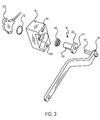
FIG. 3 is an exploded bottom perspective view of the control sensor assembly ofFIG. 2 ; -
FIG. 4 is an exploded top perspective view of the control sensor assembly ofFIG. 2 ; -
FIG. 5A is a lateral cross sectional view of the control sensor assembly ofFIG. 2 ; -
FIG. 5B is a coronal cross sectional view of the control sensor assembly ofFIG. 2 ; -
FIG. 6 is a bottom, front perspective view of a mount of the control sensor assembly ofFIG. 2 ; -
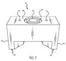
FIG. 7 is a top perspective view of the mount ofFIG. 6 ; -
FIG. 8 is a coronal cross sectional view of the mount ofFIG. 6 ; -
FIG. 9 is a perspective view of a linkage and bushing of the control sensor assembly ofFIG. 2 ; and -
FIG. 10 is a side perspective view of a header of an agricultural harvester illustrating a header height control system applicable to the subject application with various components omitted for purposes of illustration. - Reference will now be made in detail to the various aspects of the subject application illustrated in the accompanying drawings. Wherever possible, the same or like reference numbers will be used throughout the drawings to refer to the same or like features. It should be noted that the drawings are in simplified form and are not drawn to precise scale. In reference to the disclosure herein, for purposes of convenience and clarity only, directional terms such as top, bottom, left, right, above, below and diagonal, are used with respect to the accompanying drawings. Such directional terms used in conjunction with the following description of the drawings should not be construed to limit the scope of the subject application in any manner not explicitly set forth. Additionally, the term "a," as used in the specification, means "at least one." The terminology includes the words above specifically mentioned, derivatives thereof, and words of similar import.
- "About" as used herein when referring to a measurable value such as an amount, a temporal duration, and the like, is meant to encompass variations of ±20%, ±10%, ±5%, ±1%, or ±0.1% from the specified value, as such variations are appropriate.
- Referring now to the drawings, wherein aspects of the subject application are shown,
FIG. 1 illustrates several features of a frame of a header of an agricultural harvester according to the subject application. For purposes of illustration only and not by way of limitation, the header will be described e.g., as a header with a flexible cutter bar assembly, but can alternatively be any other header having a height control sensor. In addition to the frame, the header includes mechanisms for cutting crops, gathering crops and delivering crops to the agricultural harvester and is positioned relative to a ground surface upon which the agricultural harvester travels. - In
FIG. 1 , there is shown acontrol sensor assembly 12 mounted to a side of aframe 10 of a header which can be attached to the front or anterior end of a combine or similar agricultural harvester (not shown). Theframe 10 serves generally as a chassis for the header for supporting the various components of the header which are attached thereto. The header can include, among other components, a cutter bar. Such components of the header are known and therefore a detailed description of their structure, function and operation is not necessary for a complete understanding of the subject application. However, headers applicable to the subject application are disclosed inU.S. Patent Nos. 7,950,212 ;7,222,474 ; and4,414,793 . - The cutter bar severs crops as the header of the agricultural harvester travels over the field. The crops are then conveyed towards other downstream components of the agricultural harvester, e.g., auger or feeder (not shown). During operation, the cutter bar is designed to have flexibility in order to accommodate and conform generally to changing ground contours at different locations of the field. As a result, a reliable ground sensor is required to serve as indicators of ground contour changes to adjust the height position of the header and its components.
- A
control sensor assembly 12 is configured and operable according to the teachings of the subject application, for following and sensing ground contour changes and outputting signals representative thereof to a header height control system 11 (FIG. 10 ) of an agricultural harvester. Thecontrol sensor assembly 12 allows the headerheight control system 11 to raise or lower the header as required for maintaining the cutter bar at a desired level above the ground. - Referring now to
FIGS. 2-5 , there is shown a preferred embodiment of thecontrol sensor assembly 12 in accordance with the subject application. Thecontrol sensor assembly 12 includes alinkage 14, abushing 16, amount 18 and asensor 20. Thelinkage 14 connects thecontrol sensor assembly 12 to the headerheight control system 11 in a conventional, well-known manner in the art. In accordance with an aspect, thelinkage 14 has a proximal end with an aperture configured to receive ashaft 22 connecting the linkage to thebushing 16. Preferably, theshaft 22 has a circular shaped first end corresponding to the aperture of thelinkage 14 and an angular shaped second end e.g., a parallel piped shaft, opposite the first end. The angular shape of the second end corresponds to aslot 24 in thebushing 16 for connecting thelinkage 14 andbushing 16. As such, owing to the corresponding fit between the angular shaped second end and the female end of the bushing, the bushing will rotate correspondingly with rotation of the linkage about an axis defined by theshaft 22. Thelinkage 14 also has a distal end with an aperture for adjustably connecting the linkage to the header height control system.FIG. 9 shows an isolated perspective view of theshaft 22 connecting thelinkage 14 to thebushing 16. - As best shown in
FIGS. 2-4 , thebushing 16 includes a first end connected to thelinkage 14 and a second end housing a magnet 26. In accordance with an aspect, thebushing 16 is preferably configured as a flanged bushing with aflange member 28 and astem 30 extending from the flange member. Thestem 30 is preferably configured as an elongated cylindrical member. Theflange member 28 has a diameter larger than that of thestem 30. As previously discussed, theflange member 28 at the first end of thebushing 16 can include aslot 24 for receiving the angular end of theshaft 22 in order to connect the proximal end of the linkage to thebushing 16. Alternatively, theslot 24 and the angular end of theshaft 22 can be configured with any other shape suitable for its intended purpose, such as a shaft having a longitudinal cross section of a square, triangle, and the like. In accordance with another aspect, thelinkage 14 and thebushing 16 can alternatively be connected with suitable fasteners, e.g. pins, screws, bolts, and the like. - In accordance with an aspect, the second end of the
bushing 16 includes acavity 25 for housing a magnet 26 of a non-contact magnetic sensor, as further discussed below. As shown inFIG. 4 , thecavity 25 about a second end of thebushing 16 is preferably shaped to correspondingly receive and fixedly hold the magnet 26. Specifically, the magnet 26 is fixedly mounted to thebushing 16 allowing it to rotate as the bushing rotates. As further discussed below, the rotational movement of the magnet 26 with respect to thesensor 20 results in an output signal representative of a positional relationship between the header and the ground. - As best shown in
FIGS. 6-8 , themount 18 includes abody 32 and spaced apart first and secondrotational stops mount 18 is configured as a block for operatively connecting to a flexible cutter bar system. As further discussed below, the block can be appropriately modified such that thecontrol sensor assembly 12 is applicable to different types of headers, e.g., corn header, auger, draper and the like. - The
body 32 includes acounterbore 38 and a throughhole 40 extending through thecounterbore 38. The throughhole 40 extends from a first surface 42 of the body to asecond surface 44 of the body opposite the first surface and has a central longitudinal axis substantially transverse to a plane of the first surface 42. The body further includes ananterior surface 46 adjacent thecounterbore 38 and extending substantially transverse to the first surface 42. - As shown in
FIG. 6 , the throughhole 40 is configured to receive the second end of thebushing 16. As shown inFIGS. 5A and5B , aseal 48, e.g., an oil seal, can be coupled around thestem 30 of thebushing 16. Specifically, theseal 48 is shaped to slidably fit around the cylindrical shape of thestem 30 of the bushing. When assembled to the mount, theseal 48 surrounds thestem 30 and sits adjacent theflange member 28. Thus, when the throughhole 40 receives thebushing 16, theseal 48 seats within thecounterbore 38 and prevents dirt and moisture from entering. - Additionally, the body is sized so as to have a longitudinal length of the through
hole 40 to be greater than a longitudinal length of thestem 30 of thebushing 16 when the bushing is seated on the block. In other words, thebushing 16 is sized to have a longitudinal length such that the second end of the bushing is spaced from thesecond surface 44 when fully seated on the block. This way, the distal end of the bushing housing the magnet is spaced from the second surface thereby creating an air gap between the magnet and the sensor mounted to the second surface. - As shown in
FIG. 7 , the throughhole 40 extends to thesecond surface 44 of the body. Thesensor 20 is mounted onto thesecond surface 44. Preferably, thesecond surface 44 of the body comprises arecess 50 for at least partially receiving acomplementary seal 52, e.g., an O-ring, (FIG. 4 ) for preventing dirt and moisture from entering and causing thecontrol sensor assembly 12 to malfunction. When assembled, theseal 52 is positioned within therecess 50 as shown inFIGS. 5A and5B . Additionally, thesecond surface 44 can include a pair ofopenings 54 for mounting thesensor 20 onto themount 18 with suitable fasteners, e.g. pins, screws, bolts and the like. - As best shown in
FIG. 6 , the first and second spaced apartrotational stops rotational stop counterbore 38 and the firstrotational stop 34 includes an engagingsurface 56 at an angle α of about 80 to 100 degrees relative to an engagingsurface 58 of the secondrotational stop 36. Of course, the rotational stops can alternatively be configured with an angle α more or less than 80 to 100 degrees or any angle between 80 and 100 degrees. The firstrotational stop 34 and secondrotational stop 36 are respectively spaced from each other about the first surface 42 of themount 18. - The engaging surfaces 56, 58 of the respective first and second
rotational stops linkage 14 can pivot relative themount 18. While the first and secondrotational stops rotational stops linkage 14 to themount 18 in a proper orientation. In other words, the first and secondrotational stops bushing 16 and an open anterior end through which thelinkage 14 will reside in with enough play so that the inner side walls of the guide slot do not engage thelinkage 14 during general operation. - The through
hole 40 has a diameter slightly larger than the diameter of thestem 30 of thebushing 16 such that thebushing 16 is rotatable therein. As thebushing 16 rotates, thelinkage 14 connected to the second end of thebushing 16 rotates. Thelinkage 14 has a limited range of motion as defined by its connections with the header height control system and is generally restricted to movement between the first and secondrotational stops - As shown in
FIG. 6 , themount 18 includes acurved section 60 extending between the first and secondrotational stops curved section 60 is sized and configured to receive theflange member 28 of thebushing 16. Specifically, it is shaped to be complementary to the shape of theflange member 28 of thebushing 16. - The rotational stops 34, 36 each have a mounting
surface 62 substantially parallel to and spaced from the first surface 42 for engaging with the header and anopening 64 through which a fastener is passable for securing themount 18 to the frame of a header. Themount 18 can be connected to theframe 10 with any suitable fasteners, e.g. pins, screws, bolts and the like. Alternatively, themount 18 and the type of fasteners used can be adjusted to accommodate different headers, e.g., a corn header, draper, auger and the like. - When fully assembled and attached to the header, the mounting
surface 62 of therotational stops frame 10 and thelinkage 14 is positioned completely between the first and secondrotational stops linkage 14 is also positioned completely between the mountingsurface 62 of the first surface 42. - Referring to
FIGS. 6 and7 , themount 18 further includes lateral side surfaces 66 extending substantially transverse to the first surface 42. Further, each of the first and secondrotational stops - Referring back to
FIGS. 2-4 , thesensor 20 is mounted to themount 18 and spaced from the second end of thebushing 16. As discussed above, thesecond surface 44 of the body of themount 18 contains a pair ofopenings 54 for mounting thesensor 20 onto themount 18. - The
sensor 20 is preferably a non-contact magnetic sensor, such as a Hall effect sensor. In order to properly function, thecontrol sensor assembly 12 needs to properly maintain the air gap between thesensor 20 and the magnet 26. This air gap formed between thesensor 20 and the magnet 26, as a result of thebushing 16 having a longitudinal length sized less than a longitudinal length of the throughhole 40, allows for proper functionality of the non-contact magnetic sensor. Unlike currently used sensors, thesensor 20 disclosed in the subject application does not have connected moving parts. Thus, thesensor 20 disclosed in the subject application does not result in wear that can result in damage to the sensor. - As shown in
FIG. 2 , thecontrol sensor assembly 12 can be fully assembled prior to installation to theframe 10. As previously discussed, the throughhole 40 on themount 18 extends between the first surface 42 and thesecond surface 44. When fully assembled, thestem 30 of thebushing 16 is received within the throughhole 40 about the first surface 42. The proximal end of thelinkage 14 is connected to theflange member 28 of thebushing 16. Thesensor 20 is mounted about thesecond surface 44 of themount 18 such that the magnet 26 on thebushing 16 is spaced from thesensor 20 defining an air gap therebetween. When fully assembled, thecontrol sensor assembly 12 is secured to theframe 10 of the header. As previously discussed, the rotational stops 34, 36 (or guide slot) assist in proper placement of themount 18 when securing the mount onto theframe 10. - Referring now to
FIG. 10 , there is shown a side view of aframe 10 of a header. When fully assembled and installed onto theframe 10, the control sensor assembly 12 (not shown) is connected to the headerheight control system 11. Specifically, thelinkage 14 connects thecontrol sensor assembly 12 to the headerheight control system 11. During harvesting operations, the header of the agricultural harvester travels along the field. As the header travels across the field, thecutter bar assembly 76 moves up and down causing thesensor arm 68 to move up and down. Thesensor arm 68 is configured to rest on thecutter bar assembly 76. Thesensor arm 68 is also welded to asensor rod 70. Thus, when the sensor arm moves up or down, thesensor rod 70 rotates as well. The rotation of thesensor rod 70 causes a linkingmember 72 to rotate accordingly. Further, the linkingmember 72 is coupled to thelinkage 14 of thecontrol sensor assembly 12 by aconnector 74. As a result, the rotational motion of the linking member causes thelinkage 14 to rotate. - When the
linkage 14 of the control sensor assembly 12 (FIG. 2 ) rotates, thebushing 16 and the magnet 26 rotate. Specifically, the magnet 26 is fixedly mounted to thebushing 16 allowing it to rotate as the bushing rotates. The rotation of the magnet results in thesensor 20 outputting a signal representative of a positional relationship between the header and the ground. Specifically, thesensor 20 configured as a Hall effect sensor produces a voltage representative of the positional relationship between the header and the ground. - In sum, when the
cutter bar assembly 76 moves up or down, the headerheight control system 11 and its components discussed above cause movement of thelinkage 14 and magnet 26 of thecontrol sensor assembly 12. When the magnet 26 rotates, thesensor 20 produces an output voltage representative of the positional relationship between the header and the ground. The output voltage is transmitted to a computer of the agricultural harvester. - Although the
frame 10 as shown inFIG. 1 is configured to have two sensor assemblies spaced along a side end of the frame, additional sensor assemblies can be placed at additional locations along the width of the header. For example, a draper header can have four control sensor assemblies, two for tilt and two for height. Additionally, an auger head can have four control sensor assemblies, while a corn header can have between two and four or more control sensor assemblies.
Claims (15)
- A control sensor assembly (12) for an agricultural harvester characterized by a mount (18) that includes:a body (32) having a through hole (40) extending from a first surface (42) to a second surface (44) opposite the first surface (42) for receiving a bushing (16); anda first rotational stop (34) about the first surface (42) and adjacent the through hole (40).
- The control sensor assembly of claim 1, wherein the body (32) includes:a counterbore (38) and a through hole (40) extending through the counterbore (38) from a first surface (42) of the body (32) to a second surface (44) of the body (32) opposite the first surface (42), andan anterior surface (46) adjacent the counterbore (38) and extending substantially transverse to the first surface (42); andwherein the mount (18) further comprises first and second spaced apart guide surfaces (34, 36) extending from the first surface (42), wherein each guide surface (34, 36) is positioned adjacent a lateral side of the counterbore (38) and the first guide surface (34) includes an engaging surface (56) at an angle relative to an engaging surface (58) of the second guide surface (36), and wherein the first and second guide surfaces (34, 36) each have:a mounting surface (62) substantially parallel to and spaced from the first surface (42) for engaging a header, andan opening (64) through which a fastener is passable for securing the mount (18) to the header.
- The control sensor assembly of claims 1 or 2, further comprising:a linkage (14) for connection to a header height control system (11);a bushing (16) that includes:a first end connected to the linkage (14), anda second end housing a magnet (26); anda sensor (20) mounted to the mount (18) and spaced from the second end of the bushing (16).
- The control sensor assembly of claim 3, wherein the bushing (16) is a flanged bushing.
- The control sensor assembly of claims 1-4, further comprising a second rotational stop (36) spaced from the first rotational stop (34) about the first surface (42).
- The control sensor assembly of claims 1-5, wherein the through hole (40) includes a counterbore (38) for receiving a seal (48).
- The control sensor assembly of claims 1-6, wherein the second surface (44) includes a recess (50) for receiving a seal (52).
- The control sensor assembly of claims 3-7, wherein the through hole (40) has a longitudinal length greater than a longitudinal length of the bushing (16).
- The control sensor assembly of claims 3-8, wherein the bushing (16) is sized to have a longitudinal length such that the second end is spaced from the second surface (44).
- The control sensor assembly of claims 3-9, wherein the linkage (14) includes a shaft (22) for connecting to the bushing (16).
- The control sensor assembly of claims 3-10, wherein the bushing (16) is rotatable within the through hole (40).
- The control sensor assembly of claims 3-11, wherein the sensor (20) is a non-contact magnetic sensor.
- The control sensor assembly of claims 3-12, wherein the magnet (26) is spaced from the sensor (20) defining an air gap therebetween.
- The control sensor assembly of claims 3-13, wherein the linkage (14) includes a fastener for connecting to the bushing (16).
- The control sensor assembly of claims 2-14, further comprising lateral side surfaces (66) extending substantially transverse to the first surface (42), and wherein the first and second guide surfaces (34, 36) each include lateral side surfaces substantially parallel to and in line with respective lateral side surfaces (66) of the body (32).
Applications Claiming Priority (1)
| Application Number | Priority Date | Filing Date | Title |
|---|---|---|---|
| US14/870,808 US9913426B2 (en) | 2015-09-30 | 2015-09-30 | Control sensor assembly for an agricultural harvester |
Publications (2)
| Publication Number | Publication Date |
|---|---|
| EP3150971A1 true EP3150971A1 (en) | 2017-04-05 |
| EP3150971B1 EP3150971B1 (en) | 2018-11-21 |
Family
ID=57042692
Family Applications (1)
| Application Number | Title | Priority Date | Filing Date |
|---|---|---|---|
| EP16191258.9A Active EP3150971B1 (en) | 2015-09-30 | 2016-09-29 | Control sensor assembly for an agricultural harvester |
Country Status (3)
| Country | Link |
|---|---|
| US (1) | US9913426B2 (en) |
| EP (1) | EP3150971B1 (en) |
| BR (1) | BR102016021789B1 (en) |
Cited By (1)
| Publication number | Priority date | Publication date | Assignee | Title |
|---|---|---|---|---|
| EP3792214A1 (en) * | 2019-09-16 | 2021-03-17 | Zhejiang Dingli Machinery Co., LTD. | Anti-extrusion device and aerial work platform |
Families Citing this family (4)
| Publication number | Priority date | Publication date | Assignee | Title |
|---|---|---|---|---|
| EP3612683B1 (en) | 2017-04-19 | 2023-03-08 | Clark Equipment Company | Loader lift arm assembly for a power machine |
| US10568263B2 (en) | 2017-12-14 | 2020-02-25 | Cnh Industrial America Llc | Linkage assembly for header height control |
| US11383728B2 (en) | 2019-03-14 | 2022-07-12 | Cnh Industrial America Llc | System and method for collecting data associated with the operation of an agricultural machine in different operating modes |
| WO2022147607A1 (en) * | 2021-01-11 | 2022-07-14 | Troo Corporation | Line-of-sight sensor mounting system and method |
Citations (6)
| Publication number | Priority date | Publication date | Assignee | Title |
|---|---|---|---|---|
| US4414793A (en) | 1981-09-28 | 1983-11-15 | Sperry Corporation | Flexible crop harvesting header |
| CA2120169A1 (en) * | 1993-08-19 | 1995-02-20 | Herb M. Farley | Feeder Assembly Coupling Structure for an Agricultural Harvester |
| US7222474B2 (en) | 2005-04-29 | 2007-05-29 | Cnh America Llc | Ground sensing apparatus for a header of an agricultural harvesting machine |
| DE102009030955A1 (en) * | 2008-07-04 | 2010-01-07 | Aisin Seiki K.K., Kariya | System to register a rotary angle, operated by a vehicle height monitor linkage, has an input shaft in a housing with a bearing and sensor with an elastic ring rotated by a key |
| US7950212B1 (en) | 2010-03-29 | 2011-05-31 | Cnh America Llc | Cutterbar support for a crop harvesting header |
| EP2384613A1 (en) * | 2010-05-07 | 2011-11-09 | Deere & Company | Sensor for a header height control system |
Family Cites Families (10)
| Publication number | Priority date | Publication date | Assignee | Title |
|---|---|---|---|---|
| US4171606A (en) | 1978-06-30 | 1979-10-23 | Deere & Company | Attitude control for a harvester pickup |
| US4332126A (en) | 1980-09-11 | 1982-06-01 | Deere & Company | Automatic height control for a harvester header |
| US4567719A (en) | 1983-07-01 | 1986-02-04 | Deere & Company | Attitude control for a harvester pickup |
| US4641490A (en) | 1985-04-12 | 1987-02-10 | New Holland Inc. | Header height/lateral float control for combine header |
| CA2257049A1 (en) * | 1997-12-31 | 1999-06-30 | Richard Gramm | Combine header height control |
| IT1321142B1 (en) | 2000-02-29 | 2003-12-30 | New Holland Italia Spa | APPARATUS, AND RELATED METHOD, FOR THE CONTROL OF THE STRUCTURE OF A TOOL PULLED BY AN AGRICULTURAL MACHINE. |
| US7230419B2 (en) * | 2005-06-03 | 2007-06-12 | Delphi Technologies, Inc. | Rotary position sensor |
| DE102011006035A1 (en) * | 2011-03-24 | 2012-09-27 | Robert Bosch Gmbh | Displacement sensor and associated pedal unit |
| US8201388B1 (en) | 2011-05-02 | 2012-06-19 | Deere & Company | Sensor for a header height control system |
| WO2014127043A1 (en) * | 2013-02-12 | 2014-08-21 | Headsight, Inc. | Automatic calibration system for header height controller with operator feedback |
-
2015
- 2015-09-30 US US14/870,808 patent/US9913426B2/en active Active
-
2016
- 2016-09-22 BR BR102016021789-0A patent/BR102016021789B1/en active IP Right Grant
- 2016-09-29 EP EP16191258.9A patent/EP3150971B1/en active Active
Patent Citations (6)
| Publication number | Priority date | Publication date | Assignee | Title |
|---|---|---|---|---|
| US4414793A (en) | 1981-09-28 | 1983-11-15 | Sperry Corporation | Flexible crop harvesting header |
| CA2120169A1 (en) * | 1993-08-19 | 1995-02-20 | Herb M. Farley | Feeder Assembly Coupling Structure for an Agricultural Harvester |
| US7222474B2 (en) | 2005-04-29 | 2007-05-29 | Cnh America Llc | Ground sensing apparatus for a header of an agricultural harvesting machine |
| DE102009030955A1 (en) * | 2008-07-04 | 2010-01-07 | Aisin Seiki K.K., Kariya | System to register a rotary angle, operated by a vehicle height monitor linkage, has an input shaft in a housing with a bearing and sensor with an elastic ring rotated by a key |
| US7950212B1 (en) | 2010-03-29 | 2011-05-31 | Cnh America Llc | Cutterbar support for a crop harvesting header |
| EP2384613A1 (en) * | 2010-05-07 | 2011-11-09 | Deere & Company | Sensor for a header height control system |
Cited By (1)
| Publication number | Priority date | Publication date | Assignee | Title |
|---|---|---|---|---|
| EP3792214A1 (en) * | 2019-09-16 | 2021-03-17 | Zhejiang Dingli Machinery Co., LTD. | Anti-extrusion device and aerial work platform |
Also Published As
| Publication number | Publication date |
|---|---|
| BR102016021789B1 (en) | 2021-08-24 |
| US20170086366A1 (en) | 2017-03-30 |
| BR102016021789A2 (en) | 2017-04-04 |
| US9913426B2 (en) | 2018-03-13 |
| EP3150971B1 (en) | 2018-11-21 |
Similar Documents
| Publication | Publication Date | Title |
|---|---|---|
| EP3150971B1 (en) | Control sensor assembly for an agricultural harvester | |
| US12514159B2 (en) | Header height control for a harvesting head | |
| EP3937610B1 (en) | Header height control for a harvesting head | |
| RU2282971C2 (en) | Apparatus for determining height of agricultural equipment | |
| EP3516946B1 (en) | Harvester with adjustable row dividers | |
| EP3800980B1 (en) | Auto reel height | |
| EP2384613B1 (en) | Sensor for a header height control system | |
| EP3420799B1 (en) | Draper belt system | |
| EP2608652B1 (en) | Control system for a crop harvesting header | |
| US10568263B2 (en) | Linkage assembly for header height control | |
| US11058056B2 (en) | Gang arm gauge wheel height control for crop harvesting device | |
| EP3669636B1 (en) | A split reel combine header | |
| US10531608B2 (en) | Knife drive assembly for an agricultural harvester | |
| CA3245497A1 (en) | System and method to control merger operations | |
| AU2018247204B2 (en) | A drive arm assembly of a header of an agricultural harvester having an adjustable spherical knife head bearing | |
| JPS6018012Y2 (en) | Automatic steering control type reaping machine | |
| JPH0135128Y2 (en) | ||
| KR100796173B1 (en) | Position measuring device and method of measuring unmanned agricultural work machine | |
| JPS581121Y2 (en) | reaping harvester | |
| JP2605775Y2 (en) | Direction detection device in harvester | |
| JP6800903B2 (en) | Crop row detector and crop harvester using it | |
| JPH0528973Y2 (en) | ||
| JPS6334486Y2 (en) | ||
| JPH0439287B2 (en) |
Legal Events
| Date | Code | Title | Description |
|---|---|---|---|
| PUAI | Public reference made under article 153(3) epc to a published international application that has entered the european phase |
Free format text: ORIGINAL CODE: 0009012 |
|
| STAA | Information on the status of an ep patent application or granted ep patent |
Free format text: STATUS: THE APPLICATION HAS BEEN PUBLISHED |
|
| AK | Designated contracting states |
Kind code of ref document: A1 Designated state(s): AL AT BE BG CH CY CZ DE DK EE ES FI FR GB GR HR HU IE IS IT LI LT LU LV MC MK MT NL NO PL PT RO RS SE SI SK SM TR |
|
| AX | Request for extension of the european patent |
Extension state: BA ME |
|
| STAA | Information on the status of an ep patent application or granted ep patent |
Free format text: STATUS: REQUEST FOR EXAMINATION WAS MADE |
|
| 17P | Request for examination filed |
Effective date: 20171005 |
|
| RBV | Designated contracting states (corrected) |
Designated state(s): AL AT BE BG CH CY CZ DE DK EE ES FI FR GB GR HR HU IE IS IT LI LT LU LV MC MK MT NL NO PL PT RO RS SE SI SK SM TR |
|
| GRAP | Despatch of communication of intention to grant a patent |
Free format text: ORIGINAL CODE: EPIDOSNIGR1 |
|
| STAA | Information on the status of an ep patent application or granted ep patent |
Free format text: STATUS: GRANT OF PATENT IS INTENDED |
|
| RIC1 | Information provided on ipc code assigned before grant |
Ipc: G01D 5/14 20060101ALI20180419BHEP Ipc: A01D 34/00 20060101ALI20180419BHEP Ipc: G01R 33/06 20060101ALI20180419BHEP Ipc: A01D 101/00 20060101ALI20180419BHEP Ipc: G01D 11/30 20060101AFI20180419BHEP |
|
| INTG | Intention to grant announced |
Effective date: 20180517 |
|
| GRAS | Grant fee paid |
Free format text: ORIGINAL CODE: EPIDOSNIGR3 |
|
| GRAA | (expected) grant |
Free format text: ORIGINAL CODE: 0009210 |
|
| STAA | Information on the status of an ep patent application or granted ep patent |
Free format text: STATUS: THE PATENT HAS BEEN GRANTED |
|
| AK | Designated contracting states |
Kind code of ref document: B1 Designated state(s): AL AT BE BG CH CY CZ DE DK EE ES FI FR GB GR HR HU IE IS IT LI LT LU LV MC MK MT NL NO PL PT RO RS SE SI SK SM TR |
|
| REG | Reference to a national code |
Ref country code: CH Ref legal event code: EP |
|
| REG | Reference to a national code |
Ref country code: IE Ref legal event code: FG4D |
|
| REG | Reference to a national code |
Ref country code: DE Ref legal event code: R096 Ref document number: 602016007359 Country of ref document: DE |
|
| REG | Reference to a national code |
Ref country code: AT Ref legal event code: REF Ref document number: 1068080 Country of ref document: AT Kind code of ref document: T Effective date: 20181215 |
|
| REG | Reference to a national code |
Ref country code: NL Ref legal event code: MP Effective date: 20181121 |
|
| REG | Reference to a national code |
Ref country code: AT Ref legal event code: MK05 Ref document number: 1068080 Country of ref document: AT Kind code of ref document: T Effective date: 20181121 |
|
| PG25 | Lapsed in a contracting state [announced via postgrant information from national office to epo] |
Ref country code: FI Free format text: LAPSE BECAUSE OF FAILURE TO SUBMIT A TRANSLATION OF THE DESCRIPTION OR TO PAY THE FEE WITHIN THE PRESCRIBED TIME-LIMIT Effective date: 20181121 Ref country code: BG Free format text: LAPSE BECAUSE OF FAILURE TO SUBMIT A TRANSLATION OF THE DESCRIPTION OR TO PAY THE FEE WITHIN THE PRESCRIBED TIME-LIMIT Effective date: 20190221 Ref country code: LT Free format text: LAPSE BECAUSE OF FAILURE TO SUBMIT A TRANSLATION OF THE DESCRIPTION OR TO PAY THE FEE WITHIN THE PRESCRIBED TIME-LIMIT Effective date: 20181121 Ref country code: NO Free format text: LAPSE BECAUSE OF FAILURE TO SUBMIT A TRANSLATION OF THE DESCRIPTION OR TO PAY THE FEE WITHIN THE PRESCRIBED TIME-LIMIT Effective date: 20190221 Ref country code: IS Free format text: LAPSE BECAUSE OF FAILURE TO SUBMIT A TRANSLATION OF THE DESCRIPTION OR TO PAY THE FEE WITHIN THE PRESCRIBED TIME-LIMIT Effective date: 20190321 Ref country code: ES Free format text: LAPSE BECAUSE OF FAILURE TO SUBMIT A TRANSLATION OF THE DESCRIPTION OR TO PAY THE FEE WITHIN THE PRESCRIBED TIME-LIMIT Effective date: 20181121 Ref country code: AT Free format text: LAPSE BECAUSE OF FAILURE TO SUBMIT A TRANSLATION OF THE DESCRIPTION OR TO PAY THE FEE WITHIN THE PRESCRIBED TIME-LIMIT Effective date: 20181121 Ref country code: HR Free format text: LAPSE BECAUSE OF FAILURE TO SUBMIT A TRANSLATION OF THE DESCRIPTION OR TO PAY THE FEE WITHIN THE PRESCRIBED TIME-LIMIT Effective date: 20181121 Ref country code: LV Free format text: LAPSE BECAUSE OF FAILURE TO SUBMIT A TRANSLATION OF THE DESCRIPTION OR TO PAY THE FEE WITHIN THE PRESCRIBED TIME-LIMIT Effective date: 20181121 |
|
| PG25 | Lapsed in a contracting state [announced via postgrant information from national office to epo] |
Ref country code: AL Free format text: LAPSE BECAUSE OF FAILURE TO SUBMIT A TRANSLATION OF THE DESCRIPTION OR TO PAY THE FEE WITHIN THE PRESCRIBED TIME-LIMIT Effective date: 20181121 Ref country code: SE Free format text: LAPSE BECAUSE OF FAILURE TO SUBMIT A TRANSLATION OF THE DESCRIPTION OR TO PAY THE FEE WITHIN THE PRESCRIBED TIME-LIMIT Effective date: 20181121 Ref country code: RS Free format text: LAPSE BECAUSE OF FAILURE TO SUBMIT A TRANSLATION OF THE DESCRIPTION OR TO PAY THE FEE WITHIN THE PRESCRIBED TIME-LIMIT Effective date: 20181121 Ref country code: GR Free format text: LAPSE BECAUSE OF FAILURE TO SUBMIT A TRANSLATION OF THE DESCRIPTION OR TO PAY THE FEE WITHIN THE PRESCRIBED TIME-LIMIT Effective date: 20190222 Ref country code: NL Free format text: LAPSE BECAUSE OF FAILURE TO SUBMIT A TRANSLATION OF THE DESCRIPTION OR TO PAY THE FEE WITHIN THE PRESCRIBED TIME-LIMIT Effective date: 20181121 Ref country code: PT Free format text: LAPSE BECAUSE OF FAILURE TO SUBMIT A TRANSLATION OF THE DESCRIPTION OR TO PAY THE FEE WITHIN THE PRESCRIBED TIME-LIMIT Effective date: 20190321 |
|
| PG25 | Lapsed in a contracting state [announced via postgrant information from national office to epo] |
Ref country code: PL Free format text: LAPSE BECAUSE OF FAILURE TO SUBMIT A TRANSLATION OF THE DESCRIPTION OR TO PAY THE FEE WITHIN THE PRESCRIBED TIME-LIMIT Effective date: 20181121 Ref country code: DK Free format text: LAPSE BECAUSE OF FAILURE TO SUBMIT A TRANSLATION OF THE DESCRIPTION OR TO PAY THE FEE WITHIN THE PRESCRIBED TIME-LIMIT Effective date: 20181121 Ref country code: CZ Free format text: LAPSE BECAUSE OF FAILURE TO SUBMIT A TRANSLATION OF THE DESCRIPTION OR TO PAY THE FEE WITHIN THE PRESCRIBED TIME-LIMIT Effective date: 20181121 |
|
| REG | Reference to a national code |
Ref country code: DE Ref legal event code: R097 Ref document number: 602016007359 Country of ref document: DE |
|
| PG25 | Lapsed in a contracting state [announced via postgrant information from national office to epo] |
Ref country code: EE Free format text: LAPSE BECAUSE OF FAILURE TO SUBMIT A TRANSLATION OF THE DESCRIPTION OR TO PAY THE FEE WITHIN THE PRESCRIBED TIME-LIMIT Effective date: 20181121 Ref country code: RO Free format text: LAPSE BECAUSE OF FAILURE TO SUBMIT A TRANSLATION OF THE DESCRIPTION OR TO PAY THE FEE WITHIN THE PRESCRIBED TIME-LIMIT Effective date: 20181121 Ref country code: SK Free format text: LAPSE BECAUSE OF FAILURE TO SUBMIT A TRANSLATION OF THE DESCRIPTION OR TO PAY THE FEE WITHIN THE PRESCRIBED TIME-LIMIT Effective date: 20181121 Ref country code: SM Free format text: LAPSE BECAUSE OF FAILURE TO SUBMIT A TRANSLATION OF THE DESCRIPTION OR TO PAY THE FEE WITHIN THE PRESCRIBED TIME-LIMIT Effective date: 20181121 |
|
| PLBE | No opposition filed within time limit |
Free format text: ORIGINAL CODE: 0009261 |
|
| STAA | Information on the status of an ep patent application or granted ep patent |
Free format text: STATUS: NO OPPOSITION FILED WITHIN TIME LIMIT |
|
| 26N | No opposition filed |
Effective date: 20190822 |
|
| PG25 | Lapsed in a contracting state [announced via postgrant information from national office to epo] |
Ref country code: SI Free format text: LAPSE BECAUSE OF FAILURE TO SUBMIT A TRANSLATION OF THE DESCRIPTION OR TO PAY THE FEE WITHIN THE PRESCRIBED TIME-LIMIT Effective date: 20181121 |
|
| PG25 | Lapsed in a contracting state [announced via postgrant information from national office to epo] |
Ref country code: TR Free format text: LAPSE BECAUSE OF FAILURE TO SUBMIT A TRANSLATION OF THE DESCRIPTION OR TO PAY THE FEE WITHIN THE PRESCRIBED TIME-LIMIT Effective date: 20181121 |
|
| PG25 | Lapsed in a contracting state [announced via postgrant information from national office to epo] |
Ref country code: MC Free format text: LAPSE BECAUSE OF FAILURE TO SUBMIT A TRANSLATION OF THE DESCRIPTION OR TO PAY THE FEE WITHIN THE PRESCRIBED TIME-LIMIT Effective date: 20181121 |
|
| REG | Reference to a national code |
Ref country code: CH Ref legal event code: PL |
|
| PG25 | Lapsed in a contracting state [announced via postgrant information from national office to epo] |
Ref country code: CH Free format text: LAPSE BECAUSE OF NON-PAYMENT OF DUE FEES Effective date: 20190930 Ref country code: LU Free format text: LAPSE BECAUSE OF NON-PAYMENT OF DUE FEES Effective date: 20190929 Ref country code: IE Free format text: LAPSE BECAUSE OF NON-PAYMENT OF DUE FEES Effective date: 20190929 Ref country code: LI Free format text: LAPSE BECAUSE OF NON-PAYMENT OF DUE FEES Effective date: 20190930 |
|
| PG25 | Lapsed in a contracting state [announced via postgrant information from national office to epo] |
Ref country code: CY Free format text: LAPSE BECAUSE OF FAILURE TO SUBMIT A TRANSLATION OF THE DESCRIPTION OR TO PAY THE FEE WITHIN THE PRESCRIBED TIME-LIMIT Effective date: 20181121 |
|
| REG | Reference to a national code |
Ref country code: DE Ref legal event code: R082 Ref document number: 602016007359 Country of ref document: DE Representative=s name: KROHER STROBEL RECHTS- UND PATENTANWAELTE PART, DE |
|
| PG25 | Lapsed in a contracting state [announced via postgrant information from national office to epo] |
Ref country code: HU Free format text: LAPSE BECAUSE OF FAILURE TO SUBMIT A TRANSLATION OF THE DESCRIPTION OR TO PAY THE FEE WITHIN THE PRESCRIBED TIME-LIMIT; INVALID AB INITIO Effective date: 20160929 Ref country code: MT Free format text: LAPSE BECAUSE OF FAILURE TO SUBMIT A TRANSLATION OF THE DESCRIPTION OR TO PAY THE FEE WITHIN THE PRESCRIBED TIME-LIMIT Effective date: 20181121 |
|
| PG25 | Lapsed in a contracting state [announced via postgrant information from national office to epo] |
Ref country code: MK Free format text: LAPSE BECAUSE OF FAILURE TO SUBMIT A TRANSLATION OF THE DESCRIPTION OR TO PAY THE FEE WITHIN THE PRESCRIBED TIME-LIMIT Effective date: 20181121 |
|
| PGFP | Annual fee paid to national office [announced via postgrant information from national office to epo] |
Ref country code: GB Payment date: 20240924 Year of fee payment: 9 |
|
| PGFP | Annual fee paid to national office [announced via postgrant information from national office to epo] |
Ref country code: BE Payment date: 20240925 Year of fee payment: 9 |
|
| PGFP | Annual fee paid to national office [announced via postgrant information from national office to epo] |
Ref country code: FR Payment date: 20240925 Year of fee payment: 9 |
|
| PGFP | Annual fee paid to national office [announced via postgrant information from national office to epo] |
Ref country code: DE Payment date: 20250926 Year of fee payment: 10 |
|
| PGFP | Annual fee paid to national office [announced via postgrant information from national office to epo] |
Ref country code: IT Payment date: 20250922 Year of fee payment: 10 |