EP3150960A1 - System and method for affixing reference dots with respect to modeling impression materials - Google Patents
System and method for affixing reference dots with respect to modeling impression materials Download PDFInfo
- Publication number
- EP3150960A1 EP3150960A1 EP16191193.8A EP16191193A EP3150960A1 EP 3150960 A1 EP3150960 A1 EP 3150960A1 EP 16191193 A EP16191193 A EP 16191193A EP 3150960 A1 EP3150960 A1 EP 3150960A1
- Authority
- EP
- European Patent Office
- Prior art keywords
- holder
- impression material
- modeling impression
- recited
- line
- Prior art date
- Legal status (The legal status is an assumption and is not a legal conclusion. Google has not performed a legal analysis and makes no representation as to the accuracy of the status listed.)
- Granted
Links
Images



Classifications
-
- B—PERFORMING OPERATIONS; TRANSPORTING
- B29—WORKING OF PLASTICS; WORKING OF SUBSTANCES IN A PLASTIC STATE IN GENERAL
- B29C—SHAPING OR JOINING OF PLASTICS; SHAPING OF MATERIAL IN A PLASTIC STATE, NOT OTHERWISE PROVIDED FOR; AFTER-TREATMENT OF THE SHAPED PRODUCTS, e.g. REPAIRING
- B29C33/00—Moulds or cores; Details thereof or accessories therefor
- B29C33/44—Moulds or cores; Details thereof or accessories therefor with means for, or specially constructed to facilitate, the removal of articles, e.g. of undercut articles
-
- B—PERFORMING OPERATIONS; TRANSPORTING
- B29—WORKING OF PLASTICS; WORKING OF SUBSTANCES IN A PLASTIC STATE IN GENERAL
- B29C—SHAPING OR JOINING OF PLASTICS; SHAPING OF MATERIAL IN A PLASTIC STATE, NOT OTHERWISE PROVIDED FOR; AFTER-TREATMENT OF THE SHAPED PRODUCTS, e.g. REPAIRING
- B29C39/00—Shaping by casting, i.e. introducing the moulding material into a mould or between confining surfaces without significant moulding pressure; Apparatus therefor
- B29C39/02—Shaping by casting, i.e. introducing the moulding material into a mould or between confining surfaces without significant moulding pressure; Apparatus therefor for making articles of definite length, i.e. discrete articles
- B29C39/10—Shaping by casting, i.e. introducing the moulding material into a mould or between confining surfaces without significant moulding pressure; Apparatus therefor for making articles of definite length, i.e. discrete articles incorporating preformed parts or layers, e.g. casting around inserts or for coating articles
-
- B—PERFORMING OPERATIONS; TRANSPORTING
- B29—WORKING OF PLASTICS; WORKING OF SUBSTANCES IN A PLASTIC STATE IN GENERAL
- B29C—SHAPING OR JOINING OF PLASTICS; SHAPING OF MATERIAL IN A PLASTIC STATE, NOT OTHERWISE PROVIDED FOR; AFTER-TREATMENT OF THE SHAPED PRODUCTS, e.g. REPAIRING
- B29C39/00—Shaping by casting, i.e. introducing the moulding material into a mould or between confining surfaces without significant moulding pressure; Apparatus therefor
- B29C39/22—Component parts, details or accessories; Auxiliary operations
- B29C39/36—Removing moulded articles
-
- G—PHYSICS
- G01—MEASURING; TESTING
- G01B—MEASURING LENGTH, THICKNESS OR SIMILAR LINEAR DIMENSIONS; MEASURING ANGLES; MEASURING AREAS; MEASURING IRREGULARITIES OF SURFACES OR CONTOURS
- G01B11/00—Measuring arrangements characterised by the use of optical techniques
- G01B11/24—Measuring arrangements characterised by the use of optical techniques for measuring contours or curvatures
-
- G—PHYSICS
- G01—MEASURING; TESTING
- G01B—MEASURING LENGTH, THICKNESS OR SIMILAR LINEAR DIMENSIONS; MEASURING ANGLES; MEASURING AREAS; MEASURING IRREGULARITIES OF SURFACES OR CONTOURS
- G01B21/00—Measuring arrangements or details thereof, where the measuring technique is not covered by the other groups of this subclass, unspecified or not relevant
- G01B21/20—Measuring arrangements or details thereof, where the measuring technique is not covered by the other groups of this subclass, unspecified or not relevant for measuring contours or curvatures, e.g. determining profile
Definitions
- the present disclosure relates to an optical measurement system and, more particularly, to a holder for non-line of sight features.
- Reverse engineering components often employs a white-light scanning technique called ATOS (Advanced Topometric Sensor). This scanning is line of sight only.
- ATOS Advanced Topometric Sensor
- This scanning is line of sight only.
- a modeling impression material can be used to form impressions of the non-line of sight hidden area to be scanned and aligned back into the main workpiece scan at a later date. Alignment is facilitated through the use of reference dots affixed to the surface of the modeling impression material.
- One recent type of modeling impression material is a replicator material that flows into the non-line of sight feature like water, and within minutes, sets into shape for subsequent scanning.
- This liquid type modeling impression material is readily poured into the non-line of sight features but is not conducive to application of reference dots onto the surface when liquid, nor post-hardening, as the reference dots do not affix well to the solidified but relatively soft rubber-like surface.
- a holder to facilitate optical data acquisition can include a handle portion; and a float portion to at least partially support the handle portion with respect to a surface of a liquid modeling impression material.
- a further embodiment of any of the embodiments of the present disclosure may have the handle portion sized to receive at least three reference dots.
- a further embodiment of any of the embodiments of the present disclosure may have the handle portion including a cap portion transverse to a body portion.
- a further embodiment of any of the embodiments of the present disclosure may have the handle portion including a cap portion perpendicular to a body portion.
- a further embodiment of any of the embodiments of the present disclosure may have the cap portion sized to receive at least three reference dots.
- a further embodiment of any of the embodiments of the present disclosure may include a mesh area adjacent to the float portion, the mesh area at least partially immersible within the liquid modeling impression material when the float portion is on the surface of the liquid modeling impression material.
- a further embodiment of any of the embodiments of the present disclosure may include an anchor portion opposite the handle portion.
- a further embodiment of any of the embodiments of the present disclosure may have the anchor portion forming a platform receivable within the liquid modeling impression material.
- a further embodiment of any of the embodiments of the present disclosure may have the holder additively manufactured.
- a further embodiment of any of the embodiments of the present disclosure may have the holder configured to be at least partially received within a particular non-line of sight feature of a workpiece.
- a further embodiment of any of the embodiments of the present disclosure may have the holder including a flow channel to communicate the modeling impression material into the non-line of sight feature.
- a holder to facilitate optical data acquisition can include a handle portion; an anchor portion to be immersed in a liquid modeling impression material; and a float portion between the handle portion and the anchor portion, the float portion operable to at least partially support the handle portion with respect to a surface of the liquid modeling impression material.
- a further embodiment of any of the embodiments of the present disclosure may have the handle portion sized to receive at least three reference dots.
- a further embodiment of any of the embodiments of the present disclosure may include a mesh area adjacent to the anchor portion, the mesh area at least partially receivable within the liquid modeling impression material.
- a method of optical data acquisition can include communicating a liquid modeling impression material into a non-line of sight feature of a workpiece; and immersing a portion of a holder into the liquid modeling impression material.
- a further embodiment of any of the embodiments of the present disclosure may have the portion of the holder immersed in the liquid modeling impression material including an anchor portion.
- a further embodiment of any of the embodiments of the present disclosure may have the portion of the holder immersed in the liquid modeling impression including a mesh area.
- a further embodiment of any of the embodiments of the present disclosure may have the portion of the holder immersed in the liquid modeling impression separated from a handle portion by a float portion.
- a further embodiment of any of the embodiments of the present disclosure may have at least a portion of the float portion floating on the surface of the liquid modeling impression material.
- a further embodiment of any of the embodiments of the present disclosure may include communicating the liquid modeling impression material through the holder then into the non-line of sight feature of the workpiece.
- Figure 1 schematically illustrates an optical data acquisition system 20 such as ATOS (Advanced Topometric Sensor) system manufactured by GOM mbH of Braunschweig, Germany. It should be appreciated that various systems optical scanner which scans three-dimensional objects and converts the images to high density point clouds may be utilized.
- ATOS Advanced Topometric Sensor
- the optical data acquisition system 20 generally includes a light projector 22, a first image capture device 24, such as a digital camera, at a first location 26, a second image capture device 28 at second location 30 and a control subsystem 32. It should be appreciated that although particular components are separately defined, each or any of the components may be otherwise combined or segregated via hardware and/or software.
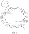
- the optical data acquisition system 20 projects a light pattern onto a workpiece 100 such as, in the illustrated non-limiting embodiment, a rotor disk ( Figure 2 ).
- the two image capture devices 24, 28 simultaneously capture images from the two measurement cameras from different angles. This stereo-setup supports accurate 3D capturing of the workpiece 10.
- a multitude of reference dots 34 randomly placed on or around the workpiece 10 may also be utilized to form a reference system to match measurements from multiple angles as the workpiece 10 is rotated on a turntable 36. That is, the size and orientation of the reference dots 34, which are of a known size and shape, are imaged then utilized by the optical data acquisition system 20 to provide a frame of reference.
- the optical data acquisition system 20 utilizes a minimum of three reference dots 34 within a limited line of sight volume provided by the two image capturing device 24, 28 in any given measurement to determine a point cloud of X, Y, Z coordinates to provide the three-dimensional data acquisition.
- the control subsystem 32 merges all the images of the encoded dots 34 to triangulate and generate a 3-dimensional relationship and location of all the encoded dots 34. Through triangulation, a surface map of the workpiece 10 is readily constructed by the control subsystem 32 to provide accurate measurement and capture of the shape and size of the visible surface of the workpiece 10.
- the workpiece 10 often includes non-line of sight features 12 such as a vane hook slot in a gas turbine engine case. It should be appreciated that various non-line of sight features 12 may benefit herefrom.
- the non-line of sight features 12 may be imaged through the use of a modeling impression material 40 such as, for example, "ScanRubber".
- ScanRubber is a compound that flows into the feature like water, and within minutes, sets into a hardened solid for subsequent scanning. Although effective, the unique liquid application obviates the setting reference dots onto the surface, as well as application post-hardening, as the reference dots do not affix well to the ScanRubber surface.
- the modeling impression material 40 is used to fill the non-line of sight features 12, removed after solidifying, then is scanned and aligned back into the overall scan of the workpiece 10.
- the modeling impression material 40 is essentially a liquid when communicated into the non-line of sight features 12 to facilitate an accurate representation. Later alignment of the non-line of sight features 12 to the surface map of the workpiece 10 is facilitated through the use of reference dots 34.
- a holder 50 upon which reference dots 34 are placed is located into the modeling impression material 40 while the modeling impression material 40 is still liquid.
- the holder 50 at least partially on the liquid modeling impression material 40 and it then retained therein upon solidification.
- the holder 50 generally includes, an anchor portion 52, a mesh area 54, a float portion 56, and a handle portion 58.
- the holder 50 may be generic in shape for common non-line of sight features such as slots, apertures, conics, etc., alternatively, the holder 50 may be specifically shaped for single use non-line of sight features and readily manufactured via, for example, additive manufacturing.
- the holder 50 is essentially non-structural, the holder 50 need only be retained in fixed position with respect to the modeling impression material 40 to provide a reference frame for the reference dots 34, and need not last much longer than the relatively short-lived modeling impression material 40.
- the holder 50 may be manufactured of materials such as plastic or other relatively inexpensive materials conducive to additive manufacturing.
- the anchor portion 52 may be relatively larger, or shaped differently, than the mesh area 54 to facilitate engagement with the modeling impression material 40 ( Figure 5 ).
- the anchor portion 52 in one embodiment, may be a rectilinear platform that extends from a lower portion of the holder 50.
- the mesh area 54 may include numerous apertures 60 and located adjacent the anchor portion 52 and/or the float portion 56. The apertures 60 of the mesh area 54 permits the modeling impression material 40 to flow therethrough in the liquid state then be readily embedded therein upon solidification.
- the mesh area 54 may be of various configurations and may optionally be utilized as additional retention structure with the anchor portion 52.
- the float portion 56 is located between the anchor portion 53 and the handle portion 58.
- the float portion 56 in one embodiment, may be a platform that extends from a lower portion of the holder 50 adjacent to the mesh area 54.
- the float portion 56 is sized and shaped to remain generally upon the surface of the modeling impression material 40 while in the liquid state such that the handle portion 58 remains above the surface ( Figure 5 ).
- the handle portion 58 extends above the float portion 56 and may be of various configurations and shapes.
- the handle portion 58 includes a cap portion 62 transverse to a body portion 64 that includes at least some of the mesh area 54.
- the cap portion 62 may be perpendicular to the body portion 64 to facilitate location of the reference dots 34 in two different measurement planes.
- any number of reference dots 34 may be located on the holder 50 to facilitate integration of the non-line of sight features 12 back into the workpiece 10 via reference dots on both the holder 50 and the workpiece 10 ( Figure 3 ). That is, the holder 50 forms a new surface inside or above the modeling impression material 40 for use as a reference dot plane as well as a handle portion for grasping, moving, and transporting the solidified material 40 to minimize handling and potential distortion thereof.
- a holder 50A include flow channels 70 to inject the modeling impression material 40 into the non-line of sight features 12 of the workpiece 10.
- the flow channels 70 may include one or more ports 72 in the cap portion 62A with one or more outlets 74 in the anchor portion 52A. It should be appreciated that various flow channel 70 paths may be utilized to facilitate injection of the liquid modeling impression material 40 into the non-line of sight features 12 which, for example, may be relatively difficult to access.
- one disclosed non-limiting embodiment of a method 200 for use of the holder 50 initially includes scanning the workpiece 10 and the reference dots thereon (step 210).
- the modeling impression material 40 is injected into the non-line of sight features 12 of the workpiece 10 (step 220).
- the holder 50 is located in the still liquid modeling impression material 40 such that the float portion 56 remains generally upon the surface of the modeling impression material 40 while in the liquid state such that the handle portion 58 remains above the surface (step 230; Figure 3 ).
- the anchor portion 52 is located below the surface and the mesh area 54 at least partially below the surface to embed into the modeling impression material 40 upon hardening. It should be appreciated that the injection of the liquid modeling impression material 40 into the non-line of sight features 12 may alternatively be performed simultaneous, or subsequent, to location of the holder 50 into the respective non-line of sight feature 12.
- the workpiece 10 with the holders 50 in place is then again scanned (step 240).
- the holders 50 include reference dots 34, the relative position of each the holder 50 is thereby oriented to the workpiece.
- the holder 50 which is embedded within the solidified modeling impression material 40, is then removed from the non-line of sight features 12 (step 250).
- the solidified modeling impression material 40 provides a positive cast of the negative non-line of sight features 12 to provide the exact contours thereof.
- Each solidified modeling impression material 40 representative of the respective non-line of sight feature 12 and the associated holder 50 is then separately scanned (step 260).
- the reference dots 34 again provide a frame of reference for each solidified modeling impression material 40 representative of the respective non-line of sight feature 12. That is, the holder 50 positions the reference dots 34 to orient the optical data acquisition system 20 at areas otherwise not sufficient surface area for the reference dots 34.
- the captured scan data for the solidified modeling impression material 40 representative of the respective non-line of sight feature 12 is then integrated in the predefined reference marker framework of the workpiece 10 (step 270). That is, the exact contours of the non-line of sight feature 12 are integrated back into the workpiece 10.
- the holder 50 beneficially provides surface inside or above the modeling impression material for use as a reference dot plane as well as a handle portion for grasping, moving, and transporting the modeling material.
Landscapes
- Physics & Mathematics (AREA)
- General Physics & Mathematics (AREA)
- Engineering & Computer Science (AREA)
- Mechanical Engineering (AREA)
Abstract
Description
- The present disclosure relates to an optical measurement system and, more particularly, to a holder for non-line of sight features.
- Reverse engineering components often employs a white-light scanning technique called ATOS (Advanced Topometric Sensor). This scanning is line of sight only. To capture non-line of sight features such as slots, a modeling impression material can be used to form impressions of the non-line of sight hidden area to be scanned and aligned back into the main workpiece scan at a later date. Alignment is facilitated through the use of reference dots affixed to the surface of the modeling impression material.
- One recent type of modeling impression material is a replicator material that flows into the non-line of sight feature like water, and within minutes, sets into shape for subsequent scanning. This liquid type modeling impression material is readily poured into the non-line of sight features but is not conducive to application of reference dots onto the surface when liquid, nor post-hardening, as the reference dots do not affix well to the solidified but relatively soft rubber-like surface.
- A holder to facilitate optical data acquisition according to one disclosed non-limiting embodiment of the present disclosure can include a handle portion; and a float portion to at least partially support the handle portion with respect to a surface of a liquid modeling impression material.
- A further embodiment of any of the embodiments of the present disclosure may have the handle portion sized to receive at least three reference dots.
- A further embodiment of any of the embodiments of the present disclosure may have the handle portion including a cap portion transverse to a body portion.
- A further embodiment of any of the embodiments of the present disclosure may have the handle portion including a cap portion perpendicular to a body portion.
- A further embodiment of any of the embodiments of the present disclosure may have the cap portion sized to receive at least three reference dots.
- A further embodiment of any of the embodiments of the present disclosure may include a mesh area adjacent to the float portion, the mesh area at least partially immersible within the liquid modeling impression material when the float portion is on the surface of the liquid modeling impression material.
- A further embodiment of any of the embodiments of the present disclosure may include an anchor portion opposite the handle portion.
- A further embodiment of any of the embodiments of the present disclosure may have the anchor portion forming a platform receivable within the liquid modeling impression material.
- A further embodiment of any of the embodiments of the present disclosure may have the holder additively manufactured.
- A further embodiment of any of the embodiments of the present disclosure may have the holder configured to be at least partially received within a particular non-line of sight feature of a workpiece.
- A further embodiment of any of the embodiments of the present disclosure may have the holder including a flow channel to communicate the modeling impression material into the non-line of sight feature.
- A holder to facilitate optical data acquisition according to another disclosed non-limiting embodiment of the present disclosure can include a handle portion; an anchor portion to be immersed in a liquid modeling impression material; and a float portion between the handle portion and the anchor portion, the float portion operable to at least partially support the handle portion with respect to a surface of the liquid modeling impression material.
- A further embodiment of any of the embodiments of the present disclosure may have the handle portion sized to receive at least three reference dots.
- A further embodiment of any of the embodiments of the present disclosure may include a mesh area adjacent to the anchor portion, the mesh area at least partially receivable within the liquid modeling impression material.
- A method of optical data acquisition according to another disclosed non-limiting embodiment of the present disclosure can include communicating a liquid modeling impression material into a non-line of sight feature of a workpiece; and immersing a portion of a holder into the liquid modeling impression material.
- A further embodiment of any of the embodiments of the present disclosure may have the portion of the holder immersed in the liquid modeling impression material including an anchor portion.
- A further embodiment of any of the embodiments of the present disclosure may have the portion of the holder immersed in the liquid modeling impression including a mesh area.
- A further embodiment of any of the embodiments of the present disclosure may have the portion of the holder immersed in the liquid modeling impression separated from a handle portion by a float portion.
- A further embodiment of any of the embodiments of the present disclosure may have at least a portion of the float portion floating on the surface of the liquid modeling impression material.
- A further embodiment of any of the embodiments of the present disclosure may include communicating the liquid modeling impression material through the holder then into the non-line of sight feature of the workpiece.
- The foregoing features and elements may be combined in various combinations without exclusivity, unless expressly indicated otherwise. These features and elements as well as the operation thereof will become more apparent in light of the following description and the accompanying drawings. It should be understood, however, the following description and drawings are intended to be exemplary in nature and non-limiting.
- Various features will become apparent to those skilled in the art from the following detailed description of the disclosed non-limiting embodiments. The drawings that accompany the detailed description can be briefly described as follows:
-
Figure 1 is a schematic view of an optical data acquisition system; -
Figure 2 is a schematic view of an example workpiece; -
Figure 3 is a schematic view of a holder to facilitate optical data acquisition within the workpiece; -
Figure 4 is a perspective view of a holder to facilitate optical data acquisition; -
Figure 5 is a perspective view of a holder affixed within modeling impression material; -
Figure 6 is a schematic view of a holder according to another embodiment; and -
Figure 7 is a method of optical data acquisition of a non-line of sight feature with the holder. -
Figure 1 schematically illustrates an opticaldata acquisition system 20 such as ATOS (Advanced Topometric Sensor) system manufactured by GOM mbH of Braunschweig, Germany. It should be appreciated that various systems optical scanner which scans three-dimensional objects and converts the images to high density point clouds may be utilized. - The optical
data acquisition system 20 generally includes alight projector 22, a firstimage capture device 24, such as a digital camera, at afirst location 26, a secondimage capture device 28 atsecond location 30 and acontrol subsystem 32. It should be appreciated that although particular components are separately defined, each or any of the components may be otherwise combined or segregated via hardware and/or software. - The optical
data acquisition system 20 projects a light pattern onto a workpiece 100 such as, in the illustrated non-limiting embodiment, a rotor disk (Figure 2 ). The twoimage capture devices workpiece 10. - A multitude of
reference dots 34 randomly placed on or around theworkpiece 10 may also be utilized to form a reference system to match measurements from multiple angles as theworkpiece 10 is rotated on aturntable 36. That is, the size and orientation of thereference dots 34, which are of a known size and shape, are imaged then utilized by the opticaldata acquisition system 20 to provide a frame of reference. - The optical
data acquisition system 20 utilizes a minimum of threereference dots 34 within a limited line of sight volume provided by the two image capturingdevice control subsystem 32 merges all the images of the encodeddots 34 to triangulate and generate a 3-dimensional relationship and location of all the encodeddots 34. Through triangulation, a surface map of theworkpiece 10 is readily constructed by thecontrol subsystem 32 to provide accurate measurement and capture of the shape and size of the visible surface of theworkpiece 10. - With reference to
Figure 2 , theworkpiece 10 often includes non-line of sight features 12 such as a vane hook slot in a gas turbine engine case. It should be appreciated that various non-line ofsight features 12 may benefit herefrom. The non-line ofsight features 12 may be imaged through the use of amodeling impression material 40 such as, for example, "ScanRubber". ScanRubber is a compound that flows into the feature like water, and within minutes, sets into a hardened solid for subsequent scanning. Although effective, the unique liquid application obviates the setting reference dots onto the surface, as well as application post-hardening, as the reference dots do not affix well to the ScanRubber surface. - The
modeling impression material 40 is used to fill the non-line ofsight features 12, removed after solidifying, then is scanned and aligned back into the overall scan of theworkpiece 10. Themodeling impression material 40 is essentially a liquid when communicated into the non-line of sight features 12 to facilitate an accurate representation. Later alignment of the non-line of sight features 12 to the surface map of theworkpiece 10 is facilitated through the use ofreference dots 34. - With reference to
Figure 3 , to facilitate placement of thereference dots 34 with respect to the non-line of sight features 12, aholder 50 upon whichreference dots 34 are placed is located into themodeling impression material 40 while themodeling impression material 40 is still liquid. In one embodiment, theholder 50 at least partially on the liquidmodeling impression material 40 and it then retained therein upon solidification. - With reference to
Figure 4 , theholder 50 generally includes, ananchor portion 52, amesh area 54, afloat portion 56, and ahandle portion 58. Theholder 50 may be generic in shape for common non-line of sight features such as slots, apertures, conics, etc., alternatively, theholder 50 may be specifically shaped for single use non-line of sight features and readily manufactured via, for example, additive manufacturing. As theholder 50 is essentially non-structural, theholder 50 need only be retained in fixed position with respect to themodeling impression material 40 to provide a reference frame for thereference dots 34, and need not last much longer than the relatively short-livedmodeling impression material 40. Theholder 50 may be manufactured of materials such as plastic or other relatively inexpensive materials conducive to additive manufacturing. - The
anchor portion 52 may be relatively larger, or shaped differently, than themesh area 54 to facilitate engagement with the modeling impression material 40 (Figure 5 ). Theanchor portion 52, in one embodiment, may be a rectilinear platform that extends from a lower portion of theholder 50. Themesh area 54 may includenumerous apertures 60 and located adjacent theanchor portion 52 and/or thefloat portion 56. Theapertures 60 of themesh area 54 permits themodeling impression material 40 to flow therethrough in the liquid state then be readily embedded therein upon solidification. Themesh area 54 may be of various configurations and may optionally be utilized as additional retention structure with theanchor portion 52. - The
float portion 56 is located between the anchor portion 53 and thehandle portion 58. Thefloat portion 56, in one embodiment, may be a platform that extends from a lower portion of theholder 50 adjacent to themesh area 54. Thefloat portion 56 is sized and shaped to remain generally upon the surface of themodeling impression material 40 while in the liquid state such that thehandle portion 58 remains above the surface (Figure 5 ). - The
handle portion 58 extends above thefloat portion 56 and may be of various configurations and shapes. In one embodiment, thehandle portion 58 includes acap portion 62 transverse to abody portion 64 that includes at least some of themesh area 54. Thecap portion 62 may be perpendicular to thebody portion 64 to facilitate location of thereference dots 34 in two different measurement planes. It should be appreciated that any number ofreference dots 34 may be located on theholder 50 to facilitate integration of the non-line of sight features 12 back into theworkpiece 10 via reference dots on both theholder 50 and the workpiece 10 (Figure 3 ). That is, theholder 50 forms a new surface inside or above themodeling impression material 40 for use as a reference dot plane as well as a handle portion for grasping, moving, and transporting the solidifiedmaterial 40 to minimize handling and potential distortion thereof. - With reference to
Figure 6 , another disclosed non-limiting embodiment of aholder 50A includeflow channels 70 to inject themodeling impression material 40 into the non-line of sight features 12 of theworkpiece 10. Theflow channels 70 may include one ormore ports 72 in thecap portion 62A with one ormore outlets 74 in theanchor portion 52A. It should be appreciated thatvarious flow channel 70 paths may be utilized to facilitate injection of the liquidmodeling impression material 40 into the non-line of sight features 12 which, for example, may be relatively difficult to access. - With reference to
Figure 7 , one disclosed non-limiting embodiment of amethod 200 for use of theholder 50 initially includes scanning theworkpiece 10 and the reference dots thereon (step 210). Next, themodeling impression material 40 is injected into the non-line of sight features 12 of the workpiece 10 (step 220). Next, theholder 50 is located in the still liquidmodeling impression material 40 such that thefloat portion 56 remains generally upon the surface of themodeling impression material 40 while in the liquid state such that thehandle portion 58 remains above the surface (step 230;Figure 3 ). Theanchor portion 52 is located below the surface and themesh area 54 at least partially below the surface to embed into themodeling impression material 40 upon hardening. It should be appreciated that the injection of the liquidmodeling impression material 40 into the non-line of sight features 12 may alternatively be performed simultaneous, or subsequent, to location of theholder 50 into the respective non-line ofsight feature 12. - The
workpiece 10 with theholders 50 in place is then again scanned (step 240). As theholders 50 includereference dots 34, the relative position of each theholder 50 is thereby oriented to the workpiece. - The
holder 50, which is embedded within the solidifiedmodeling impression material 40, is then removed from the non-line of sight features 12 (step 250). The solidifiedmodeling impression material 40 provides a positive cast of the negative non-line of sight features 12 to provide the exact contours thereof. - Each solidified
modeling impression material 40 representative of the respective non-line ofsight feature 12 and the associatedholder 50 is then separately scanned (step 260). Thereference dots 34 again provide a frame of reference for each solidifiedmodeling impression material 40 representative of the respective non-line ofsight feature 12. That is, theholder 50 positions thereference dots 34 to orient the opticaldata acquisition system 20 at areas otherwise not sufficient surface area for thereference dots 34. - The captured scan data for the solidified
modeling impression material 40 representative of the respective non-line ofsight feature 12 is then integrated in the predefined reference marker framework of the workpiece 10 (step 270). That is, the exact contours of the non-line ofsight feature 12 are integrated back into theworkpiece 10. - The
holder 50 beneficially provides surface inside or above the modeling impression material for use as a reference dot plane as well as a handle portion for grasping, moving, and transporting the modeling material. - The use of the terms "a", "an", "the", and similar references in the context of description (especially in the context of the following claims) are to be construed to cover both the singular and the plural, unless otherwise indicated herein or specifically contradicted by context. The modifier "about" used in connection with a quantity is inclusive of the stated value and has the meaning dictated by the context (e.g., it includes the degree of error associated with measurement of the particular quantity). All ranges disclosed herein are inclusive of the endpoints, and the endpoints are independently combinable with each other. It should be appreciated that relative positional terms such as "forward", "aft", "upper", "lower", "above", "below", and the like are with reference to normal operational attitude and should not be considered otherwise limiting.
- Although the different non-limiting embodiments have specific illustrated components, the embodiments of this invention are not limited to those particular combinations. It is possible to use some of the components or features from any of the non-limiting embodiments in combination with features or components from any of the other non-limiting embodiments.
- It should be appreciated that like reference numerals identify corresponding or similar elements throughout the several drawings. It should also be appreciated that although a particular component arrangement is disclosed in the illustrated embodiment, other arrangements will benefit herefrom.
- Although particular step sequences are shown, described, and claimed, it should be understood that steps may be performed in any order, separated or combined unless otherwise indicated and will still benefit from the present disclosure.
- The foregoing description is exemplary rather than defined by the limitations within. Various non-limiting embodiments are disclosed herein, however, one of ordinary skill in the art would recognize that various modifications and variations in light of the above teachings will fall within the scope of the appended claims. It is therefore to be understood that within the scope of the appended claims, the disclosure may be practiced other than as specifically described. For that reason the appended claims should be studied to determine true scope and content.
Claims (14)
- A holder to facilitate optical data acquisition, comprising:a handle portion; anda float portion to at least partially support the handle portion with respect to a surface of a liquid modeling impression material.
- The holder as recited in claim 1, wherein the handle portion is sized to receive at least three reference dots.
- The holder as recited in claim 1 or claim 2, wherein the handle portion includes a cap portion transverse to a body portion.
- The holder as recited in claim 1 or claim 2, wherein the handle portion includes a cap portion perpendicular to a body portion.
- The holder as recited in any preceding claim, further comprising a mesh area adjacent to the float portion, the mesh area at least partially immersible within the liquid modeling impression material when the float portion is on the surface of the liquid modeling impression material.
- The holder as recited in any preceding claim, further comprising an anchor portion opposite the handle portion.
- The holder as recited in claim 6, wherein the anchor portion forms a platform receivable within the liquid modeling impression material.
- The holder as recited in any preceding claim, wherein the holder is additively manufactured.
- The holder as recited in any preceding claim, wherein the holder is configured to be at least partially received within a particular non-line of sight feature of a workpiece.
- The holder as recited in claim 9, wherein the holder includes a flow channel to communicate the modeling impression material into the non-line of sight feature.
- A holder as claimed in claim 1 or claim 2, further comprising:an anchor portion to be immersed in said liquid modeling impression material; andwherein said float portion is between the handle portion and the anchor portion.
- The holder as recited in claim 11, further comprising a mesh area adjacent to the anchor portion, the mesh area at least partially receivable within the liquid modeling impression material.
- A method of optical data acquisition, comprising:communicating a liquid modeling impression material into a non-line of sight feature of a workpiece; andimmersing a portion of a holder as claimed in any previous claim into the liquid modeling impression material.
- The method as recited in claim 13, further comprising communicating the liquid modeling impression material through the holder then into the non-line of sight feature of the workpiece.
Applications Claiming Priority (1)
| Application Number | Priority Date | Filing Date | Title |
|---|---|---|---|
| US14/872,362 US10137605B2 (en) | 2015-10-01 | 2015-10-01 | System and method for affixing reference dots with respect to modeling impression materials |
Publications (2)
| Publication Number | Publication Date |
|---|---|
| EP3150960A1 true EP3150960A1 (en) | 2017-04-05 |
| EP3150960B1 EP3150960B1 (en) | 2019-03-27 |
Family
ID=57153263
Family Applications (1)
| Application Number | Title | Priority Date | Filing Date |
|---|---|---|---|
| EP16191193.8A Active EP3150960B1 (en) | 2015-10-01 | 2016-09-28 | Method for affixing reference dots with respect to modeling impression materials |
Country Status (3)
| Country | Link |
|---|---|
| US (2) | US10137605B2 (en) |
| EP (1) | EP3150960B1 (en) |
| SG (1) | SG10201608173QA (en) |
Citations (4)
| Publication number | Priority date | Publication date | Assignee | Title |
|---|---|---|---|---|
| US6279246B1 (en) * | 1997-04-21 | 2001-08-28 | N.V. Krypton Electronic Engineering | Device and method for determining the position of a point |
| KR101100443B1 (en) * | 2010-01-28 | 2011-12-29 | 현대제철 주식회사 | Method of measuring the surface shape of the section steel |
| WO2014024014A1 (en) * | 2012-08-07 | 2014-02-13 | Toschi Vignola S.R.L. | A stick for supporting ice creams |
| WO2014134057A1 (en) * | 2013-02-27 | 2014-09-04 | United Technologies Corporation | Inspecting one or more apertures of a component using moldable material |
Family Cites Families (20)
| Publication number | Priority date | Publication date | Assignee | Title |
|---|---|---|---|---|
| US4830443A (en) | 1984-05-31 | 1989-05-16 | Robotic Vision Systems, Inc. | Three-dimensional volumetric sensor |
| US5018803A (en) | 1985-02-04 | 1991-05-28 | Robotic Vision Systems, Inc. | Three-dimensional volumetric sensor |
| US5438449A (en) | 1987-11-25 | 1995-08-01 | Raytheon Company | Beam pointing switch |
| EP0574686A2 (en) | 1992-05-13 | 1993-12-22 | The Spectranetics Corporation | Linear scan method and system for cloupling energy into an optical fiber bundle |
| US5504595A (en) | 1992-05-26 | 1996-04-02 | Symbol Technologies, Inc. | Holographic scanning |
| US5900954A (en) | 1992-06-01 | 1999-05-04 | Symbol Technologies, Inc. | Machine readable record carrier with hologram |
| JPH06242715A (en) | 1993-02-17 | 1994-09-02 | Komatsu Ltd | Three-dimensional image display device |
| US5465142A (en) | 1993-04-30 | 1995-11-07 | Northrop Grumman Corporation | Obstacle avoidance system for helicopters and other aircraft |
| DE19952962B4 (en) | 1999-11-03 | 2004-07-01 | Sirona Dental Systems Gmbh | Method for producing a drilling aid for a dental implant |
| US6516897B2 (en) * | 2000-02-25 | 2003-02-11 | Michael C. Thompson | Self-contained excavator and anchor apparatus and method |
| US7728989B2 (en) * | 2004-02-13 | 2010-06-01 | Optimet, Optical Metrology Ltd. | Double-sided measurement of dental objects using an optical scanner |
| DE102005018656B4 (en) | 2005-04-21 | 2007-04-12 | GOM - Gesellschaft für Optische Meßtechnik mbH | Projector for an arrangement for the three-dimensional optical measurement of objects |
| US7574035B2 (en) * | 2006-04-07 | 2009-08-11 | United Technologies Corporation | System and method for inspection of hole location on turbine airfoils |
| US7578178B2 (en) | 2007-09-28 | 2009-08-25 | United Technologies Corporation | Method of inspecting turbine internal cooling features using non-contact scanners |
| US7869026B2 (en) | 2007-12-21 | 2011-01-11 | United Technologies Corp. | Targeted artifacts and methods for evaluating 3-D coordinate system measurement accuracy of optical 3-D measuring systems using such targeted artifacts |
| US7573586B1 (en) | 2008-06-02 | 2009-08-11 | United Technologies Corporation | Method and system for measuring a coating thickness |
| TWI353885B (en) | 2009-06-26 | 2011-12-11 | Primax Electronics Ltd | Thickness detecting mechanism |
| EP2428795A1 (en) * | 2010-09-14 | 2012-03-14 | Siemens Aktiengesellschaft | Apparatus and method for automatic inspection of through-holes of a component |
| DE102011078016A1 (en) * | 2011-06-22 | 2012-12-27 | Aloys Wobben | tower manufacturing |
| CN103292691A (en) * | 2012-02-29 | 2013-09-11 | 西门子公司 | Method for detecting cooling hole of combustion gas turbine blade |
-
2015
- 2015-10-01 US US14/872,362 patent/US10137605B2/en active Active
-
2016
- 2016-09-28 EP EP16191193.8A patent/EP3150960B1/en active Active
- 2016-09-30 SG SG10201608173QA patent/SG10201608173QA/en unknown
-
2018
- 2018-10-23 US US16/167,742 patent/US10675790B2/en active Active
Patent Citations (4)
| Publication number | Priority date | Publication date | Assignee | Title |
|---|---|---|---|---|
| US6279246B1 (en) * | 1997-04-21 | 2001-08-28 | N.V. Krypton Electronic Engineering | Device and method for determining the position of a point |
| KR101100443B1 (en) * | 2010-01-28 | 2011-12-29 | 현대제철 주식회사 | Method of measuring the surface shape of the section steel |
| WO2014024014A1 (en) * | 2012-08-07 | 2014-02-13 | Toschi Vignola S.R.L. | A stick for supporting ice creams |
| WO2014134057A1 (en) * | 2013-02-27 | 2014-09-04 | United Technologies Corporation | Inspecting one or more apertures of a component using moldable material |
Also Published As
| Publication number | Publication date |
|---|---|
| US10675790B2 (en) | 2020-06-09 |
| US20170095948A1 (en) | 2017-04-06 |
| EP3150960B1 (en) | 2019-03-27 |
| SG10201608173QA (en) | 2017-05-30 |
| US10137605B2 (en) | 2018-11-27 |
| US20190054665A1 (en) | 2019-02-21 |
Similar Documents
| Publication | Publication Date | Title |
|---|---|---|
| US11145077B2 (en) | Device and method for obtaining depth information from a scene | |
| US8315425B2 (en) | Method for comparison of 3D computer model and as-built situation of an industrial plant | |
| CN103714571B (en) | A kind of based on photogrammetric single camera three-dimensional rebuilding method | |
| CN102506830B (en) | Vision-based positioning method and device | |
| CN105643092A (en) | Method for regaining coordinates of workpiece through CCD during combined machining | |
| CN109669468A (en) | Program is used in measuring device, unmanned plane and its control device, control method and control | |
| CN106595528A (en) | Digital speckle-based telecentric microscopic binocular stereoscopic vision measurement method | |
| WO2017101150A1 (en) | Method and device for calibrating structured-light three-dimensional scanning system | |
| KR20140053870A (en) | 3d streets | |
| EP1571460A3 (en) | Satellite positioning apparatus and current position determining method | |
| CN101363712A (en) | Dynamic precision target for calibration of 3D color digital system | |
| CN112862966B (en) | Method, device, equipment and storage medium for constructing surface three-dimensional model | |
| JP6635649B2 (en) | Data overlay program and data overlay method | |
| CN110281238A (en) | Assembly line multi-robot scaling method, device, computer equipment and storage medium | |
| CN114494627A (en) | City model generation method, device, equipment and computer readable storage medium | |
| CN110009693A (en) | A kind of Fast Blind scaling method of light-field camera | |
| JP2014106118A (en) | Digital surface model creation method, and digital surface model creation device | |
| US10675790B2 (en) | System and method for affixing reference dots with respect to modeling impression materials | |
| CN113052974A (en) | Method and device for reconstructing three-dimensional surface of object | |
| CN107705335A (en) | Demarcate the non-method that ken line sweeps laser range finder and measures camera orientation altogether | |
| KR101006728B1 (en) | Automatic 3D Coordinate Measurement Using Center Projection and Image Matching | |
| CN109712197A (en) | A kind of airfield runway gridding scaling method and system | |
| JP2009276073A (en) | Plane estimating method, curved surface estimating method, and plane estimating device | |
| CN109141363A (en) | Unmanned plane high-precision dual camera oblique photograph measuring system | |
| CN105651201B (en) | Three-dimensional scanner and 3-D scanning method |
Legal Events
| Date | Code | Title | Description |
|---|---|---|---|
| PUAI | Public reference made under article 153(3) epc to a published international application that has entered the european phase |
Free format text: ORIGINAL CODE: 0009012 |
|
| STAA | Information on the status of an ep patent application or granted ep patent |
Free format text: STATUS: THE APPLICATION HAS BEEN PUBLISHED |
|
| AK | Designated contracting states |
Kind code of ref document: A1 Designated state(s): AL AT BE BG CH CY CZ DE DK EE ES FI FR GB GR HR HU IE IS IT LI LT LU LV MC MK MT NL NO PL PT RO RS SE SI SK SM TR |
|
| AX | Request for extension of the european patent |
Extension state: BA ME |
|
| STAA | Information on the status of an ep patent application or granted ep patent |
Free format text: STATUS: REQUEST FOR EXAMINATION WAS MADE |
|
| 17P | Request for examination filed |
Effective date: 20171005 |
|
| RBV | Designated contracting states (corrected) |
Designated state(s): AL AT BE BG CH CY CZ DE DK EE ES FI FR GB GR HR HU IE IS IT LI LT LU LV MC MK MT NL NO PL PT RO RS SE SI SK SM TR |
|
| STAA | Information on the status of an ep patent application or granted ep patent |
Free format text: STATUS: EXAMINATION IS IN PROGRESS |
|
| 17Q | First examination report despatched |
Effective date: 20180426 |
|
| RIC1 | Information provided on ipc code assigned before grant |
Ipc: G01B 11/24 20060101ALI20180912BHEP Ipc: B29C 39/10 20060101ALI20180912BHEP Ipc: B29C 33/44 20060101ALI20180912BHEP Ipc: G01B 21/20 20060101AFI20180912BHEP Ipc: B29C 39/36 20060101ALI20180912BHEP |
|
| GRAP | Despatch of communication of intention to grant a patent |
Free format text: ORIGINAL CODE: EPIDOSNIGR1 |
|
| STAA | Information on the status of an ep patent application or granted ep patent |
Free format text: STATUS: GRANT OF PATENT IS INTENDED |
|
| INTG | Intention to grant announced |
Effective date: 20181023 |
|
| GRAS | Grant fee paid |
Free format text: ORIGINAL CODE: EPIDOSNIGR3 |
|
| GRAA | (expected) grant |
Free format text: ORIGINAL CODE: 0009210 |
|
| STAA | Information on the status of an ep patent application or granted ep patent |
Free format text: STATUS: THE PATENT HAS BEEN GRANTED |
|
| AK | Designated contracting states |
Kind code of ref document: B1 Designated state(s): AL AT BE BG CH CY CZ DE DK EE ES FI FR GB GR HR HU IE IS IT LI LT LU LV MC MK MT NL NO PL PT RO RS SE SI SK SM TR |
|
| REG | Reference to a national code |
Ref country code: GB Ref legal event code: FG4D |
|
| REG | Reference to a national code |
Ref country code: CH Ref legal event code: EP |
|
| REG | Reference to a national code |
Ref country code: AT Ref legal event code: REF Ref document number: 1113625 Country of ref document: AT Kind code of ref document: T Effective date: 20190415 |
|
| REG | Reference to a national code |
Ref country code: IE Ref legal event code: FG4D |
|
| REG | Reference to a national code |
Ref country code: DE Ref legal event code: R096 Ref document number: 602016011504 Country of ref document: DE |
|
| PG25 | Lapsed in a contracting state [announced via postgrant information from national office to epo] |
Ref country code: SE Free format text: LAPSE BECAUSE OF FAILURE TO SUBMIT A TRANSLATION OF THE DESCRIPTION OR TO PAY THE FEE WITHIN THE PRESCRIBED TIME-LIMIT Effective date: 20190327 Ref country code: FI Free format text: LAPSE BECAUSE OF FAILURE TO SUBMIT A TRANSLATION OF THE DESCRIPTION OR TO PAY THE FEE WITHIN THE PRESCRIBED TIME-LIMIT Effective date: 20190327 Ref country code: NO Free format text: LAPSE BECAUSE OF FAILURE TO SUBMIT A TRANSLATION OF THE DESCRIPTION OR TO PAY THE FEE WITHIN THE PRESCRIBED TIME-LIMIT Effective date: 20190627 Ref country code: LT Free format text: LAPSE BECAUSE OF FAILURE TO SUBMIT A TRANSLATION OF THE DESCRIPTION OR TO PAY THE FEE WITHIN THE PRESCRIBED TIME-LIMIT Effective date: 20190327 |
|
| REG | Reference to a national code |
Ref country code: NL Ref legal event code: MP Effective date: 20190327 |
|
| PG25 | Lapsed in a contracting state [announced via postgrant information from national office to epo] |
Ref country code: GR Free format text: LAPSE BECAUSE OF FAILURE TO SUBMIT A TRANSLATION OF THE DESCRIPTION OR TO PAY THE FEE WITHIN THE PRESCRIBED TIME-LIMIT Effective date: 20190628 Ref country code: NL Free format text: LAPSE BECAUSE OF FAILURE TO SUBMIT A TRANSLATION OF THE DESCRIPTION OR TO PAY THE FEE WITHIN THE PRESCRIBED TIME-LIMIT Effective date: 20190327 Ref country code: HR Free format text: LAPSE BECAUSE OF FAILURE TO SUBMIT A TRANSLATION OF THE DESCRIPTION OR TO PAY THE FEE WITHIN THE PRESCRIBED TIME-LIMIT Effective date: 20190327 Ref country code: RS Free format text: LAPSE BECAUSE OF FAILURE TO SUBMIT A TRANSLATION OF THE DESCRIPTION OR TO PAY THE FEE WITHIN THE PRESCRIBED TIME-LIMIT Effective date: 20190327 Ref country code: LV Free format text: LAPSE BECAUSE OF FAILURE TO SUBMIT A TRANSLATION OF THE DESCRIPTION OR TO PAY THE FEE WITHIN THE PRESCRIBED TIME-LIMIT Effective date: 20190327 Ref country code: BG Free format text: LAPSE BECAUSE OF FAILURE TO SUBMIT A TRANSLATION OF THE DESCRIPTION OR TO PAY THE FEE WITHIN THE PRESCRIBED TIME-LIMIT Effective date: 20190627 |
|
| REG | Reference to a national code |
Ref country code: AT Ref legal event code: MK05 Ref document number: 1113625 Country of ref document: AT Kind code of ref document: T Effective date: 20190327 |
|
| PG25 | Lapsed in a contracting state [announced via postgrant information from national office to epo] |
Ref country code: IT Free format text: LAPSE BECAUSE OF FAILURE TO SUBMIT A TRANSLATION OF THE DESCRIPTION OR TO PAY THE FEE WITHIN THE PRESCRIBED TIME-LIMIT Effective date: 20190327 Ref country code: ES Free format text: LAPSE BECAUSE OF FAILURE TO SUBMIT A TRANSLATION OF THE DESCRIPTION OR TO PAY THE FEE WITHIN THE PRESCRIBED TIME-LIMIT Effective date: 20190327 Ref country code: CZ Free format text: LAPSE BECAUSE OF FAILURE TO SUBMIT A TRANSLATION OF THE DESCRIPTION OR TO PAY THE FEE WITHIN THE PRESCRIBED TIME-LIMIT Effective date: 20190327 Ref country code: RO Free format text: LAPSE BECAUSE OF FAILURE TO SUBMIT A TRANSLATION OF THE DESCRIPTION OR TO PAY THE FEE WITHIN THE PRESCRIBED TIME-LIMIT Effective date: 20190327 Ref country code: EE Free format text: LAPSE BECAUSE OF FAILURE TO SUBMIT A TRANSLATION OF THE DESCRIPTION OR TO PAY THE FEE WITHIN THE PRESCRIBED TIME-LIMIT Effective date: 20190327 Ref country code: AL Free format text: LAPSE BECAUSE OF FAILURE TO SUBMIT A TRANSLATION OF THE DESCRIPTION OR TO PAY THE FEE WITHIN THE PRESCRIBED TIME-LIMIT Effective date: 20190327 Ref country code: PT Free format text: LAPSE BECAUSE OF FAILURE TO SUBMIT A TRANSLATION OF THE DESCRIPTION OR TO PAY THE FEE WITHIN THE PRESCRIBED TIME-LIMIT Effective date: 20190727 Ref country code: SK Free format text: LAPSE BECAUSE OF FAILURE TO SUBMIT A TRANSLATION OF THE DESCRIPTION OR TO PAY THE FEE WITHIN THE PRESCRIBED TIME-LIMIT Effective date: 20190327 |
|
| PG25 | Lapsed in a contracting state [announced via postgrant information from national office to epo] |
Ref country code: PL Free format text: LAPSE BECAUSE OF FAILURE TO SUBMIT A TRANSLATION OF THE DESCRIPTION OR TO PAY THE FEE WITHIN THE PRESCRIBED TIME-LIMIT Effective date: 20190327 Ref country code: SM Free format text: LAPSE BECAUSE OF FAILURE TO SUBMIT A TRANSLATION OF THE DESCRIPTION OR TO PAY THE FEE WITHIN THE PRESCRIBED TIME-LIMIT Effective date: 20190327 |
|
| PG25 | Lapsed in a contracting state [announced via postgrant information from national office to epo] |
Ref country code: AT Free format text: LAPSE BECAUSE OF FAILURE TO SUBMIT A TRANSLATION OF THE DESCRIPTION OR TO PAY THE FEE WITHIN THE PRESCRIBED TIME-LIMIT Effective date: 20190327 Ref country code: IS Free format text: LAPSE BECAUSE OF FAILURE TO SUBMIT A TRANSLATION OF THE DESCRIPTION OR TO PAY THE FEE WITHIN THE PRESCRIBED TIME-LIMIT Effective date: 20190727 |
|
| REG | Reference to a national code |
Ref country code: DE Ref legal event code: R097 Ref document number: 602016011504 Country of ref document: DE |
|
| PG25 | Lapsed in a contracting state [announced via postgrant information from national office to epo] |
Ref country code: DK Free format text: LAPSE BECAUSE OF FAILURE TO SUBMIT A TRANSLATION OF THE DESCRIPTION OR TO PAY THE FEE WITHIN THE PRESCRIBED TIME-LIMIT Effective date: 20190327 |
|
| PLBE | No opposition filed within time limit |
Free format text: ORIGINAL CODE: 0009261 |
|
| STAA | Information on the status of an ep patent application or granted ep patent |
Free format text: STATUS: NO OPPOSITION FILED WITHIN TIME LIMIT |
|
| PG25 | Lapsed in a contracting state [announced via postgrant information from national office to epo] |
Ref country code: SI Free format text: LAPSE BECAUSE OF FAILURE TO SUBMIT A TRANSLATION OF THE DESCRIPTION OR TO PAY THE FEE WITHIN THE PRESCRIBED TIME-LIMIT Effective date: 20190327 |
|
| 26N | No opposition filed |
Effective date: 20200103 |
|
| PG25 | Lapsed in a contracting state [announced via postgrant information from national office to epo] |
Ref country code: TR Free format text: LAPSE BECAUSE OF FAILURE TO SUBMIT A TRANSLATION OF THE DESCRIPTION OR TO PAY THE FEE WITHIN THE PRESCRIBED TIME-LIMIT Effective date: 20190327 |
|
| PG25 | Lapsed in a contracting state [announced via postgrant information from national office to epo] |
Ref country code: MC Free format text: LAPSE BECAUSE OF FAILURE TO SUBMIT A TRANSLATION OF THE DESCRIPTION OR TO PAY THE FEE WITHIN THE PRESCRIBED TIME-LIMIT Effective date: 20190327 |
|
| REG | Reference to a national code |
Ref country code: CH Ref legal event code: PL |
|
| PG25 | Lapsed in a contracting state [announced via postgrant information from national office to epo] |
Ref country code: IE Free format text: LAPSE BECAUSE OF NON-PAYMENT OF DUE FEES Effective date: 20190928 Ref country code: CH Free format text: LAPSE BECAUSE OF NON-PAYMENT OF DUE FEES Effective date: 20190930 Ref country code: LU Free format text: LAPSE BECAUSE OF NON-PAYMENT OF DUE FEES Effective date: 20190928 Ref country code: LI Free format text: LAPSE BECAUSE OF NON-PAYMENT OF DUE FEES Effective date: 20190930 |
|
| REG | Reference to a national code |
Ref country code: BE Ref legal event code: MM Effective date: 20190930 |
|
| PG25 | Lapsed in a contracting state [announced via postgrant information from national office to epo] |
Ref country code: BE Free format text: LAPSE BECAUSE OF NON-PAYMENT OF DUE FEES Effective date: 20190930 |
|
| PG25 | Lapsed in a contracting state [announced via postgrant information from national office to epo] |
Ref country code: CY Free format text: LAPSE BECAUSE OF FAILURE TO SUBMIT A TRANSLATION OF THE DESCRIPTION OR TO PAY THE FEE WITHIN THE PRESCRIBED TIME-LIMIT Effective date: 20190327 |
|
| PG25 | Lapsed in a contracting state [announced via postgrant information from national office to epo] |
Ref country code: HU Free format text: LAPSE BECAUSE OF FAILURE TO SUBMIT A TRANSLATION OF THE DESCRIPTION OR TO PAY THE FEE WITHIN THE PRESCRIBED TIME-LIMIT; INVALID AB INITIO Effective date: 20160928 Ref country code: MT Free format text: LAPSE BECAUSE OF FAILURE TO SUBMIT A TRANSLATION OF THE DESCRIPTION OR TO PAY THE FEE WITHIN THE PRESCRIBED TIME-LIMIT Effective date: 20190327 |
|
| PG25 | Lapsed in a contracting state [announced via postgrant information from national office to epo] |
Ref country code: MK Free format text: LAPSE BECAUSE OF FAILURE TO SUBMIT A TRANSLATION OF THE DESCRIPTION OR TO PAY THE FEE WITHIN THE PRESCRIBED TIME-LIMIT Effective date: 20190327 |
|
| REG | Reference to a national code |
Ref country code: DE Ref legal event code: R081 Ref document number: 602016011504 Country of ref document: DE Owner name: RAYTHEON TECHNOLOGIES CORPORATION (N.D.GES.D.S, US Free format text: FORMER OWNER: UNITED TECHNOLOGIES CORPORATION, FARMINGTON, CONN., US Ref country code: DE Ref legal event code: R081 Ref document number: 602016011504 Country of ref document: DE Owner name: RTX CORPORATION (N.D.GES.D. STAATES DELAWARE),, US Free format text: FORMER OWNER: UNITED TECHNOLOGIES CORPORATION, FARMINGTON, CONN., US |
|
| P01 | Opt-out of the competence of the unified patent court (upc) registered |
Effective date: 20230520 |
|
| PGFP | Annual fee paid to national office [announced via postgrant information from national office to epo] |
Ref country code: DE Payment date: 20250820 Year of fee payment: 10 |
|
| PGFP | Annual fee paid to national office [announced via postgrant information from national office to epo] |
Ref country code: GB Payment date: 20250820 Year of fee payment: 10 |
|
| PGFP | Annual fee paid to national office [announced via postgrant information from national office to epo] |
Ref country code: FR Payment date: 20250821 Year of fee payment: 10 |
|
| REG | Reference to a national code |
Ref country code: DE Ref legal event code: R081 Ref document number: 602016011504 Country of ref document: DE Owner name: RTX CORPORATION (N.D.GES.D. STAATES DELAWARE),, US Free format text: FORMER OWNER: RAYTHEON TECHNOLOGIES CORPORATION (N.D.GES.D.STAATES DELAWARE), ARLINGTON, VA, US |