EP3150877A1 - Clutch actuator of a motor vehicle and related motor vehicle - Google Patents
Clutch actuator of a motor vehicle and related motor vehicle Download PDFInfo
- Publication number
- EP3150877A1 EP3150877A1 EP16191486.6A EP16191486A EP3150877A1 EP 3150877 A1 EP3150877 A1 EP 3150877A1 EP 16191486 A EP16191486 A EP 16191486A EP 3150877 A1 EP3150877 A1 EP 3150877A1
- Authority
- EP
- European Patent Office
- Prior art keywords
- pusher
- actuation
- motor vehicle
- clutch actuator
- transmission
- Prior art date
- Legal status (The legal status is an assumption and is not a legal conclusion. Google has not performed a legal analysis and makes no representation as to the accuracy of the status listed.)
- Granted
Links
Images

Classifications
-
- F—MECHANICAL ENGINEERING; LIGHTING; HEATING; WEAPONS; BLASTING
- F16—ENGINEERING ELEMENTS AND UNITS; GENERAL MEASURES FOR PRODUCING AND MAINTAINING EFFECTIVE FUNCTIONING OF MACHINES OR INSTALLATIONS; THERMAL INSULATION IN GENERAL
- F16D—COUPLINGS FOR TRANSMITTING ROTATION; CLUTCHES; BRAKES
- F16D28/00—Electrically-actuated clutches
-
- F—MECHANICAL ENGINEERING; LIGHTING; HEATING; WEAPONS; BLASTING
- F16—ENGINEERING ELEMENTS AND UNITS; GENERAL MEASURES FOR PRODUCING AND MAINTAINING EFFECTIVE FUNCTIONING OF MACHINES OR INSTALLATIONS; THERMAL INSULATION IN GENERAL
- F16D—COUPLINGS FOR TRANSMITTING ROTATION; CLUTCHES; BRAKES
- F16D23/00—Details of mechanically-actuated clutches not specific for one distinct type
- F16D23/12—Mechanical clutch-actuating mechanisms arranged outside the clutch as such
- F16D2023/123—Clutch actuation by cams, ramps or ball-screw mechanisms
Definitions
- This invention relates to a clutch actuator of a motor vehicle and a related motor vehicle.
- hydraulic systems involve risks due to leaks and oozing, require accurate maintenance of the related gasket seals, periodic replacement of the working liquid that is characterised by a marked hygroscopicity and can be subject to phenomena of fading for example due to overheating.
- hydraulic devices require a manual type actuation, by lever or pedal, which is inevitably linked to the strength of the driver. This involves for example the need to over-dimension some system components, such as the diameters of the discs of a clutch pack, or even the diameter of a brake disc, so that the devices can be actuated effectively without requiring excessive manual effort from the user.
- manual actuation of a hydraulic device is subject to the sensitivity of the user who feels the stiffness of the actuation lever or pedal and adjusts the actuation force accordingly.
- Often systems are subject to variations of stiffness for example due to variations of the hydraulic fluid caused by temperature, the presence of micro-bubbles, the pliability of hydraulic hoses and so on. Therefore the actuation force that the user must impart to the actuating member, whether a lever or pedal, can vary over time to achieve the same final technical effect. The user is not able to adapt the actuation force to the changed system conditions and thus is not always able to obtain maximum performance from the system.
- Hydraulic actuation systems do not always allow an adequate reduction of bulk and weight.
- a motor vehicle clutch actuator comprising an actuation command of the clutch actuator, configured to be actuated by a user, and an actuator body that at least partially houses a pusher configured to be operatively connected to a clutch to determine its engagement and disengagement, the pusher translating along an actuation direction, motor means suitable to move said pusher and operatively connected to the actuation command to be actuated by the latter, and transmission means that mechanically connect the motor means to the pusher, wherein the motor means are arranged parallel to the transmission means along a direction of transmission perpendicular to said actuation direction, wherein the transmission means comprise an epicycloidal step-down gear mounted coaxially to the direction of transmission, and comprise an alternating rectilinear motion mechanism that includes a connecting rod and a crank that lie on a plane perpendicular to the direction of transmission, wherein the connecting rod is doubly hinged to the pusher and to the crank, and wherein the crank is integral in rotation with an output shaft of the epicycloidal step-down
- the motor means are placed coaxially to the transmission means in a direction of transmission perpendicular to said actuation direction.
- the actuation command comprises a lever and/or pedal and/or a button operable manually by a user to operate said motor means, or automatically operable.
- the actuator body comprises a cylinder, directed in the actuation direction, which houses and guides the movement of the pusher in the same actuation direction.
- the transmission means provide for an alternating rectilinear motion mechanism which comprises a cam, integral in rotation with an output shaft of the epicycloidal step-down gear, parallel to the direction of transmission, wherein a piston, which acts as a pusher, is directly hinged to said cam.
- a motor shaft of the motor means is coaxial and integral in rotation with said output shaft of the epicycloidal step-down gear.
- the epicycloidal step-down gear is configured so as to achieve a reduction of the speed between a motor shaft of the motor means and an output shaft of the epicycloidal step-down gear in order to reduce the angular velocity and therefore increase the torque in the transmission from the motor means to the output shaft.
- the actuator body comprises a single body directed parallel to the direction of transmission, which houses, arranged in series, the motor means and the epicycloidal step-down gear, and a lateral appendage, directed parallel to the actuation direction, which houses the mechanism comprising the connecting rod and the crank as well as the pusher.
- the transmission means comprise a ball bearing screw mechanism, fitted with a ball bearing screw mechanically connected to the motor means, and a nut, which meshes coaxially with said ball bearing screw, said nut being operatively connected to the pusher in order to move the pusher in the actuation direction.
- the nut is integral with a wedge, which moves parallel to the direction of transmission, the wedge intercepting a counter-shaped wall of the pusher in order to move the pusher in the actuation direction.
- a ball bearing is inserted, so as to achieve a rolling friction at the interface between the wedge and the pusher.
- the actuator body comprises an attachment plate to a casing of the clutch group, configured to allow the direct attachment of the clutch actuator to said clutch group.
- the clutch actuator comprises a control unit programmed to control the motor means in the actuation of the pusher and operatively connected to the manual actuation device.
- control unit is programmed to receive an on-off type actuation request from the user via said actuation command, and to modulate the speed and/or movement of the pusher as a function of a pre-imposed actuation rule.
- control unit is programmed so as to automatically actuate the pusher to disengage the clutch, disconnecting at least partially an input shaft from an output shaft of the clutch, in case of locking, when downshifting, of one or more wheels of the motor vehicle kinematically connected to said output shaft.
- control unit is programmed so as to automatically actuate the pusher to disengage the clutch, disconnecting at least partially an input shaft from an output shaft of the clutch, in case of spinning, when accelerating, of one or more wheels of the motor vehicle kinematically connected to said output shaft.
- said control unit is operatively connected to a controller of an associable vehicle, the control unit being programmed so as to cooperate with the controller in changing gear and/or the dynamic control of the vehicle.
- reference number 4 generally designates a clutch actuator of a motor vehicle comprising an actuation command (not shown) of the clutch actuator, configured to be operated by a user, and an actuator body 8.
- Motor vehicle means any motor vehicle having at least two wheels, such as for example a motorcycle, a tricycle, having two front or rear wheels, a quadricycle and any motor vehicle having two or more axles, regardless of the type of drive, size and power.
- actuation command can comprise a lever and/or a pedal and/or a button manually operable by a user to actuate the clutch actuator 4 and, as better described below, motor means 12 of the clutch actuator 4.
- Said actuation command can also be actuated automatically, for example by a control unit of the motor vehicle.
- the actuation command can be manual, manually operable on request by the user (by moving a lever or a pedal or by pressing a button) or it can be automatic.
- Automatic actuation command means that the actuation of the clutch actuator, for example to change gear or perform a stability control of the vehicle, can occur even without the "manual" action of the user, i.e., the actuator can be actuated spontaneously as a function of the operating parameters of the vehicle on which it is applied, as better specified in the rest of the description.
- the user by actuating the actuation command, selectively requests the actuation of the clutch actuator 4.
- the actuator body 8 houses at least partially a pusher 16 configured to be operatively connected to a clutch (not shown) to determine its engagement and disengagement.
- the pusher can be kinematically connected to the clutch or its actuating member by means of the interposition of a rod or return (not shown).
- Engagement of the clutch means that the input shaft and the output shaft of the clutch, connected respectively to the motor shaft and the primary shaft of the gearbox, are integrally connected in rotation to each other so as to enable the transmission of torque from the motor shaft to the gearbox and therefore to the drive wheel(s).
- the connection between said shafts occurs typically by means of discs axially facing each other and provided with friction facings, in a known manner.
- Disengagement of the clutch means that the input shaft and the output shaft of the clutch are connected in rotation with each other in such a way as not to enable the transmission of torque from the motor shaft to the gearbox and therefore to the drive wheel(s).
- the pusher 16 is configured to translate along an actuation direction S-S.
- the pusher 16 can in turn be connected kinematically to the clutch through returns or mechanical connection of any kind.
- the actuator body 8 houses the motor means 12 suitable to move said pusher 16 and operatively connected to the actuation command thereof to be actuated by the latter.
- the motor means 12 preferably comprise an electric motor.
- the actuator body 8 also houses transmission means 20 which mechanically connect the motor means 12 to the pusher 16.
- the motor means 12 are arranged parallel to the transmission means 20 in a transmission direction X-X perpendicular to said actuation direction S-S.
- motor means (12) are arranged parallel to the transmission means (20) in a direction of transmission (X-X) perpendicular to said actuation direction(S-S.
- the actuator body 8 comprises a cylinder 24, directed in the actuation direction S-S, which houses and guides the movement of the pusher 16 in said actuation direction S-S.
- the cylinder is at least partially counter-shaped with respect to the pusher in order to guide the rectilinear movement parallel to the actuation direction S-S.
- the transmission means 20 comprise an epicycloidal step-down gear 28 mounted coaxially to the direction of transmission X-X.
- the epicycloidal step-down gear 28 comprises a plurality of gears and an output shaft 32 which is preferably coaxial and integral in rotation to a motor shaft 36 of the motor means 12.
- the transmission means 20 comprise an alternating rectilinear motion mechanism 38 which comprises a connecting rod 40 and a crank 44 which lie on a plane perpendicular to the direction of transmission X-X, wherein the connecting rod 40 is doubly hinged to the pusher 16 and to the crank 44, and wherein the crank 44 is integral in rotation with the output shaft 32 of the epicycloidal step-down gear 28 parallel to the direction of transmission X-X.
- the connecting rod 40 and the crank 44 revolve around a rotation axis parallel to the direction of transmission X-X and the pusher 16 translates, according to a reciprocating rectilinear motion, along a direction parallel to the actuation direction S-S. Therefore, the rotation motion of the motor shaft 36 of the motor means 12 around the direction of transmission X-X is transformed, thanks to the mechanism with connecting rod 40 and crank 44, into reciprocating rectilinear motion of the pusher 16 along the actuation direction S-S, perpendicular to said direction of transmission.
- the transmission means 20 provide for an alternating rectilinear motion mechanism 38 which comprises a cam 37, integral in rotation with the motor shaft 36 to which a piston 39 which acts as a pusher 16 is directly hinged.
- actuation of the pusher 16 or piston 39 can provide for the opposite rotation of the motor means 12 so as to rotate the motor shaft 36 of the motor means 12 in one direction or in the opposite direction as a function of the need to realise the engagement or disengagement of the clutch.
- the kinematic law that connects the translation motion of the pusher 16 with the rotation motion of the motor shaft 36 is not linear, as is known, but rather sinusoidal. Obviously, even the kinematic law between the respective linear (of translation) and angular (rotational) velocities of, respectively, the pusher 16 and the motor shaft 36, are not linear.
- the epicycloidal step-down gear 28 has the advantage of allowing a substantial reduction of the speed between the motor shaft 36 and the output shaft 32, while maintaining the extremely limited overall dimensions, so as to increase the torque of the motor means 12 and effectively actuate the pusher 16.
- the epicycloidal step-down gear 28 is configured so as to reduce the angular velocity and thus increase the torque in the transmission from the motor means 12 to the output shaft 32.
- the actuator body 8 is a cylindrical body coaxial and parallel to the direction of transmission X-X which houses, arranged in series with each other, the motor means 12, the epicycloidal step-down gear 28 and the mechanism comprising the connecting rod 40 and the crank 44.
- the actuator body 8 is a cylindrical body axisymmetric with respect to the direction of transmission X-X.
- the actuator body 8 comprises a single body 48 directed parallel to the direction of transmission which houses, arranged in series, the motor means 12, the epicycloidal step-down gear 28, and a lateral appendage 52, directed parallel to the actuation direction S-S, which houses the mechanism comprising the connecting rod 40 and the crank 44 as well as the pusher 16.
- the single body 48 and the lateral appendage 52 can be secured to each other by threaded connection means 56 so as to allow a quick assembly/disassembly of the clutch actuator 4.
- the transmission means 20 comprise a ball bearing screw mechanism 60, fitted with a ball bearing screw 64 mechanically connected to the motor means 12, and a nut 68 which meshes coaxially with said ball bearing screw 64, in which the nut 68 is operatively connected to the pusher 16 in order to move the pusher 16 in the actuation direction S-S.
- the nut 68 is integral with a wedge 72 which moves parallel to the direction of transmission X-X, the wedge 72 intercepting a counter-shaped wall 76 of the pusher 16 in order to move the pusher 16 in the actuation direction S-S.
- the ball bearing screw mechanism 60 allows transforming the rotation motion of the motor shaft 36 of the motor means 12 and the rotation motion of the ball bearing screw 64 around the actuation direction X-X into translational motion of the nut 68 parallel to the same actuation direction X-X.
- the wedge 72 in turn transforms the translation motion of the nut 68 parallel to the actuation direction X-X into translational motion of the pusher along the actuation direction S-S.
- an action of thrust and friction is exerted that is transformed into actuation stroke of the pusher 16.
- transition between a forward stroke and a return stroke of the pusher can be obtained by reversing the rotation of the motor means: in fact, this reversal of rotation results in the reversal of the direction of translation of the nut along the direction of transmission, and thus the reversal of the actuation stroke of the pusher along the actuation direction S-S.
- a ball bearing 80 is inserted, so as to achieve a rolling, and no longer sliding, friction at the interface between the wedge 72 and the pusher 16.
- the actuator body 8 comprises a single body 48 directed parallel to the direction of transmission which houses, arranged in series, the motor means 12 and a lateral appendage 52, directed parallel to the actuation direction S-S, which houses the ball bearing screw mechanism 60 and the pusher 16.
- the single body 48 and the lateral appendage 52 can be secured to each other by threaded connection means 56 so as to allow a quick assembly/disassembly of the clutch actuator 4.
- the actuator body comprises an attachment plate 84 to a casing of a clutch group, configured to allow the direct attachment of the clutch actuator 4 on said clutch group.
- the clutch actuator 4 comprises a control unit 88 programmed to control the motor means 12 in the actuation of the pusher 16 and operatively connected to the manual actuation device.
- control unit 88 is directly fixed to the actuator body 8, for example by means of suitable fixing clamps 90.
- the control unit 88 can be programmed to receive an on-off type actuation request from the user via said actuation command, and to modulate the speed and/or movement of the pusher as a function of a pre-imposed actuation rule.
- the actuation request by the user can occur by pressing a button or also by moving a lever and/or a pedal.
- the clutch actuator is able to ensure the best possible traction, for example as a function of various vehicle operating parameters.
- the above examples relate to examples of manual actuation commands of the actuator 4, in which the user selectively decides whether or not to actuate the clutch actuator 4 at will even though, as seen, the user does not modulate its actual operation, i.e., determining the intervention rule over time.
- control unit 88 is programmed so as to automatically actuate the pusher 16 to disengage the clutch, disconnecting at least partially an input shaft from an output shaft of the clutch, in case of locking, when downshifting, of one or more wheels of the motor vehicle kinematically connected to said output shaft of the clutch.
- the control unit 88 automatically disengages the clutch, by acting appropriately on the pusher 16, so as to restore the rolling of the wheel(s).
- control unit 88 acts as a slipper device, without requiring any modification to the clutch, as in known solutions that are complex and heavy.
- This actuation of the control unit 88 occurs independently of the will of the user, and indeed occurs precisely to correct a user's dangerous manoeuvre such as for example downshifting to an excessive rotation regime in relation to the gear engaged, the rolling of the motor vehicle, the inclination of the motorcycle and/or the traction conditions of the road surface. This achieves an active control of the dynamic stability of the vehicle.
- control unit 88 is programmed so as to automatically actuate the pusher 16 to disengage the clutch, disconnecting at least partially an input shaft from an output shaft of the clutch, in case of spinning when accelerating, of one or more wheels of the motor vehicle kinematically connected to said output shaft.
- control unit 88 occurs independently of the will of the user, and indeed occurs precisely to correct a user's dangerous manoeuvre such as for example an excessive request for power in relation to the gear engaged, the rolling of the motor vehicle, the inclination of the motorcycle and/or the traction conditions of the road surface.
- control unit 88 is programmed so as to automatically actuate the pusher 16 to disengage the clutch, disconnecting at least partially an input shaft from an output shaft of the clutch to perform an automatic gear change or a robotised manual change (AMT): this can occur according to mappings stored in the control unit, for example as a function of the forward speed and/or torque delivered and/or the gear engaged, and/or the angle of inclination of the motor vehicle.
- AMT robotised manual change
- control unit 88 is operatively connected to a controller of an associable vehicle, and the control unit is programmed so as to cooperate with the controller in changing gear and/or the dynamic control of the vehicle.
- Such cooperation is useful in order to integrate the overall management of the stability control of the motor vehicle, which can also provide for interaction with auxiliary devices such as anti-lock braking devices and strategies for managing the power delivered by the engine, as well as the gear shift actuator devices.
- auxiliary devices such as anti-lock braking devices and strategies for managing the power delivered by the engine, as well as the gear shift actuator devices.
- this invention allows overcoming the drawbacks presented in the prior art.
- the clutch actuator of this invention allows obtaining the direct actuation of the clutch without the use of a hydraulic system and can be installed, for example, on a racing motorcycle.
- the actuator device allows reducing bulk and masses with respect to a conventional hydraulic system.
- this invention allows the possibility of introducing a direct electrical actuation system of the clutch which introduces advantages in terms of modulation of the clutch when starting, reduction of masses and greater speed in the gear change.
- the hydraulic part is no longer needed and can be removed and replaced by a simple button for managing starting and changes.
- the servo-mechanism of this invention can generate forces greater than those obtained with conventional hydraulic systems since no longer connected to the direct actuation of the driver and thus his strength. In this way it is possible to dimension the clutch pack differently, reducing its dimensions, weight (for example using carbon plates instead of the classic sintered) and rotational inertia, while maintaining performance unaltered.
- the actuator according to the invention allows automatically adapting to possible variations of operation of the components to be actuated; for example, it is able to automatically compensate for wear of the clutch discs without requiring any particular adaptation or sensitivity from the user.
- the solution of this invention can replace complicated mechanical systems present in the clutch to control so-called reverse torque and function as a "slipper" device in downshifting for the rear wheel: in this way the same clutch can be simplified and lightened, while also reducing the gyroscopic effect on the vehicle.
- the slipper clutch effect may be obtained automatically, by at least partially opening the clutch, i.e., if necessary disengaging the motor shaft from the primary shaft of the gearbox in the event of incipient locking of one or more rear wheels of the motor vehicle, for example during a phase of downshifting and/or sudden release of the throttle control during which the reverse torque supplied by the engine can generate locking phenomena in the drive tyres.
- the actuator device of this invention is configured so that it can be replaced with a conventional manual actuator without requiring any modification to the clutch and/or engine group of the vehicle on which it is applied. Therefore, the actuator of this invention can be advantageously applied as a retro-fit to motor vehicles previously equipped with the manual clutch actuator devices without requiring additional changes. This possibility is ensured by the fact that the actuator device, as seen, is particularly compact and lightweight, while still being able to ensure the proper action of the clutch of the motor vehicle in any operating condition and, indeed, with greater efficiency and better performance with respect to a manual type actuation.
Landscapes
- Engineering & Computer Science (AREA)
- General Engineering & Computer Science (AREA)
- Physics & Mathematics (AREA)
- Electromagnetism (AREA)
- Mechanical Engineering (AREA)
- Hydraulic Clutches, Magnetic Clutches, Fluid Clutches, And Fluid Joints (AREA)
- Mechanical Operated Clutches (AREA)
- Steering Devices For Bicycles And Motorcycles (AREA)
- Pulleys (AREA)
Abstract
- a pusher configured to be operatively connected to a clutch to determine its engagement and disengagement, the pusher moving in an actuation direction,
- motor means suitable to move said pusher and operatively connected to the actuation command to be operated by the latter,
- transmission means which mechanically connect the motor means to the pusher,
- wherein the motor means are arranged parallel to the transmission means in a transmission direction perpendicular to said actuation direction.
Description
- This invention relates to a clutch actuator of a motor vehicle and a related motor vehicle.
- In particular, in the automotive field, electronically controlled servo-actuator systems are becoming increasingly popular for optimising the operation of some vehicle systems, such as for example the braking system, gearbox, etc.
- These servo-actuated systems are increasingly replacing more traditional, manually operated, hydraulic systems, which involve several problems and limitations.
- In fact, the presence of hydraulic systems for the actuation of vehicle components imposes the presence of pipes and related fluid reservoirs, as well as the need to periodically drain the system.
- Obviously, hydraulic systems involve risks due to leaks and oozing, require accurate maintenance of the related gasket seals, periodic replacement of the working liquid that is characterised by a marked hygroscopicity and can be subject to phenomena of fading for example due to overheating.
- Furthermore, hydraulic devices require a manual type actuation, by lever or pedal, which is inevitably linked to the strength of the driver. This involves for example the need to over-dimension some system components, such as the diameters of the discs of a clutch pack, or even the diameter of a brake disc, so that the devices can be actuated effectively without requiring excessive manual effort from the user.
- However, this increases the masses of system components and the related gyroscopic effects, for example of clutch discs or brake discs, which increase inertia and worsen the dynamic behaviour of the vehicle.
- Moreover, manual actuation of a hydraulic device is subject to the sensitivity of the user who feels the stiffness of the actuation lever or pedal and adjusts the actuation force accordingly. Often systems are subject to variations of stiffness for example due to variations of the hydraulic fluid caused by temperature, the presence of micro-bubbles, the pliability of hydraulic hoses and so on. Therefore the actuation force that the user must impart to the actuating member, whether a lever or pedal, can vary over time to achieve the same final technical effect. The user is not able to adapt the actuation force to the changed system conditions and thus is not always able to obtain maximum performance from the system.
- In the case of a clutch, for example, extreme sensitivity is required to determine the correct insertion, in order to effectively transmit torque to the wheels, especially when starting. If one thinks of motor vehicle racing and, for example, motorcycles, an incorrect clutch release, for example when starting, can kill the engine or spin the drive wheel (or drive wheels), with consequent loss of numerous positions.
- Also, as seen, in racing such servo-actuator systems must allow obtaining maximum dynamic performance, while ensuring reduced bulk and weight. In the field of motor racing, whether with cars or motorcycles, these requirements of lightness and reduced bulk are even more urgent since the spaces available are themselves reduced, as well as the masses of the vehicles, for which the weight of vehicle's actuator devices is a not negligible percentage.
- Hydraulic actuation systems do not always allow an adequate reduction of bulk and weight.
- Therefore, there is a need to solve the drawbacks and limitations mentioned in reference to the prior art.
- This need is met by a clutch actuator of a motor vehicle according to claim 1.
- In particular, this requirement is satisfied by a motor vehicle clutch actuator comprising an actuation command of the clutch actuator, configured to be actuated by a user, and an actuator body that at least partially houses a pusher configured to be operatively connected to a clutch to determine its engagement and disengagement, the pusher translating along an actuation direction, motor means suitable to move said pusher and operatively connected to the actuation command to be actuated by the latter, and transmission means that mechanically connect the motor means to the pusher, wherein the motor means are arranged parallel to the transmission means along a direction of transmission perpendicular to said actuation direction, wherein the transmission means comprise an epicycloidal step-down gear mounted coaxially to the direction of transmission, and comprise an alternating rectilinear motion mechanism that includes a connecting rod and a crank that lie on a plane perpendicular to the direction of transmission, wherein the connecting rod is doubly hinged to the pusher and to the crank, and wherein the crank is integral in rotation with an output shaft of the epicycloidal step-down gear, parallel to the direction of transmission.
- According to a possible embodiment, the motor means are placed coaxially to the transmission means in a direction of transmission perpendicular to said actuation direction.
- According to a possible embodiment, the actuation command comprises a lever and/or pedal and/or a button operable manually by a user to operate said motor means, or automatically operable.
- According to a possible embodiment, the actuator body comprises a cylinder, directed in the actuation direction, which houses and guides the movement of the pusher in the same actuation direction.
- According to a possible embodiment, the transmission means provide for an alternating rectilinear motion mechanism which comprises a cam, integral in rotation with an output shaft of the epicycloidal step-down gear, parallel to the direction of transmission, wherein a piston, which acts as a pusher, is directly hinged to said cam.
- According to a possible embodiment, a motor shaft of the motor means is coaxial and integral in rotation with said output shaft of the epicycloidal step-down gear.
- According to a possible embodiment, the epicycloidal step-down gear is configured so as to achieve a reduction of the speed between a motor shaft of the motor means and an output shaft of the epicycloidal step-down gear in order to reduce the angular velocity and therefore increase the torque in the transmission from the motor means to the output shaft.
- According to a possible embodiment, the actuator body comprises a single body directed parallel to the direction of transmission, which houses, arranged in series, the motor means and the epicycloidal step-down gear, and a lateral appendage, directed parallel to the actuation direction, which houses the mechanism comprising the connecting rod and the crank as well as the pusher.
- According to a possible embodiment, the transmission means comprise a ball bearing screw mechanism, fitted with a ball bearing screw mechanically connected to the motor means, and a nut, which meshes coaxially with said ball bearing screw, said nut being operatively connected to the pusher in order to move the pusher in the actuation direction.
- According to a possible embodiment, the nut is integral with a wedge, which moves parallel to the direction of transmission, the wedge intercepting a counter-shaped wall of the pusher in order to move the pusher in the actuation direction.
- According to a possible embodiment, between the wedge and the pusher a ball bearing is inserted, so as to achieve a rolling friction at the interface between the wedge and the pusher.
- According to a possible embodiment, the actuator body comprises an attachment plate to a casing of the clutch group, configured to allow the direct attachment of the clutch actuator to said clutch group.
- According to a possible embodiment, the clutch actuator comprises a control unit programmed to control the motor means in the actuation of the pusher and operatively connected to the manual actuation device.
- According to a possible embodiment, the control unit is programmed to receive an on-off type actuation request from the user via said actuation command, and to modulate the speed and/or movement of the pusher as a function of a pre-imposed actuation rule.
- According to a possible embodiment, the control unit is programmed so as to automatically actuate the pusher to disengage the clutch, disconnecting at least partially an input shaft from an output shaft of the clutch, in case of locking, when downshifting, of one or more wheels of the motor vehicle kinematically connected to said output shaft.
- According to a possible embodiment, the control unit is programmed so as to automatically actuate the pusher to disengage the clutch, disconnecting at least partially an input shaft from an output shaft of the clutch, in case of spinning, when accelerating, of one or more wheels of the motor vehicle kinematically connected to said output shaft.
- According to a possible embodiment, said control unit is operatively connected to a controller of an associable vehicle, the control unit being programmed so as to cooperate with the controller in changing gear and/or the dynamic control of the vehicle.
- Further characteristics and advantages of this invention will be more understandable from the following description of its preferred and non-limiting examples of embodiments, in which:
-
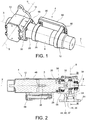
Figure 1 is a perspective view of a clutch actuator of a motor vehicle according to this invention; -
Figure 2 is a sectional view of the clutch actuator ofFigure 1 ; -
Figure 3 is a sectional view of the clutch actuator ofFigure 1 , along the section plane III-III ofFigure 2 ; -
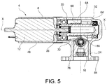
Figure 4 is a perspective view of a clutch actuator of a motor vehicle according to a further embodiment of this invention; -
Figure 5 is a sectional view of the clutch actuator ofFigure 4 . - The elements, or parts of elements, in common between the embodiments described below will be indicated with the same reference numbers.
- With reference to the above figures,
reference number 4 generally designates a clutch actuator of a motor vehicle comprising an actuation command (not shown) of the clutch actuator, configured to be operated by a user, and anactuator body 8. Motor vehicle means any motor vehicle having at least two wheels, such as for example a motorcycle, a tricycle, having two front or rear wheels, a quadricycle and any motor vehicle having two or more axles, regardless of the type of drive, size and power. - It should be noted that the actuation command can comprise a lever and/or a pedal and/or a button manually operable by a user to actuate the
clutch actuator 4 and, as better described below, motor means 12 of theclutch actuator 4. Said actuation command can also be actuated automatically, for example by a control unit of the motor vehicle. - Therefore, the actuation command can be manual, manually operable on request by the user (by moving a lever or a pedal or by pressing a button) or it can be automatic. Automatic actuation command means that the actuation of the clutch actuator, for example to change gear or perform a stability control of the vehicle, can occur even without the "manual" action of the user, i.e., the actuator can be actuated spontaneously as a function of the operating parameters of the vehicle on which it is applied, as better specified in the rest of the description.
- Preferably, the user, by actuating the actuation command, selectively requests the actuation of the
clutch actuator 4. - The
actuator body 8 houses at least partially apusher 16 configured to be operatively connected to a clutch (not shown) to determine its engagement and disengagement. For example, the pusher can be kinematically connected to the clutch or its actuating member by means of the interposition of a rod or return (not shown). - Engagement of the clutch means that the input shaft and the output shaft of the clutch, connected respectively to the motor shaft and the primary shaft of the gearbox, are integrally connected in rotation to each other so as to enable the transmission of torque from the motor shaft to the gearbox and therefore to the drive wheel(s). The connection between said shafts occurs typically by means of discs axially facing each other and provided with friction facings, in a known manner.
- Disengagement of the clutch means that the input shaft and the output shaft of the clutch are connected in rotation with each other in such a way as not to enable the transmission of torque from the motor shaft to the gearbox and therefore to the drive wheel(s).
- The
pusher 16 is configured to translate along an actuation direction S-S. - The
pusher 16 can in turn be connected kinematically to the clutch through returns or mechanical connection of any kind. - In addition, the
actuator body 8 houses the motor means 12 suitable to move saidpusher 16 and operatively connected to the actuation command thereof to be actuated by the latter. - The motor means 12 preferably comprise an electric motor.
- The
actuator body 8 also houses transmission means 20 which mechanically connect the motor means 12 to thepusher 16. - Advantageously, the motor means 12 are arranged parallel to the transmission means 20 in a transmission direction X-X perpendicular to said actuation direction S-S.
- wherein the motor means (12) are arranged parallel to the transmission means (20) in a direction of transmission (X-X) perpendicular to said actuation direction(S-S.
- According to an embodiment, the
actuator body 8 comprises acylinder 24, directed in the actuation direction S-S, which houses and guides the movement of thepusher 16 in said actuation direction S-S. The cylinder is at least partially counter-shaped with respect to the pusher in order to guide the rectilinear movement parallel to the actuation direction S-S. - According to an embodiment, the transmission means 20 comprise an epicycloidal step-
down gear 28 mounted coaxially to the direction of transmission X-X. - The epicycloidal step-
down gear 28 comprises a plurality of gears and anoutput shaft 32 which is preferably coaxial and integral in rotation to amotor shaft 36 of the motor means 12. - According to an embodiment, the transmission means 20 comprise an alternating
rectilinear motion mechanism 38 which comprises a connecting rod 40 and a crank 44 which lie on a plane perpendicular to the direction of transmission X-X, wherein the connecting rod 40 is doubly hinged to thepusher 16 and to the crank 44, and wherein the crank 44 is integral in rotation with theoutput shaft 32 of the epicycloidal step-down gear 28 parallel to the direction of transmission X-X. - Therefore, the connecting rod 40 and the crank 44 revolve around a rotation axis parallel to the direction of transmission X-X and the
pusher 16 translates, according to a reciprocating rectilinear motion, along a direction parallel to the actuation direction S-S. Therefore, the rotation motion of themotor shaft 36 of the motor means 12 around the direction of transmission X-X is transformed, thanks to the mechanism with connecting rod 40 and crank 44, into reciprocating rectilinear motion of thepusher 16 along the actuation direction S-S, perpendicular to said direction of transmission. - According to an embodiment, the transmission means 20 provide for an alternating
rectilinear motion mechanism 38 which comprises a cam 37, integral in rotation with themotor shaft 36 to which a piston 39 which acts as apusher 16 is directly hinged. - This means that, as a function of the rotation of the crank 44 or of the cam 37, the
pusher 16 or piston 39 will have a different actuation stroke; also as a function of such rotation, the stroke can be cancelled and its direction be reversed. - It should be noted that the actuation of the
pusher 16 or piston 39 can provide for the opposite rotation of the motor means 12 so as to rotate themotor shaft 36 of the motor means 12 in one direction or in the opposite direction as a function of the need to realise the engagement or disengagement of the clutch. - It is also possible to provide for an actuation of the
motor shaft 36 of the motor means 12 always in the same direction of rotation: in this way, every half turn, i.e., rotation of 180 degrees, will pass to the actuation extremes of the stroke of thepusher 16, i.e., to the upper and lower dead points of the pusher as a function of the need to have engagement and disengagement conditions of the clutch. - Moreover, the kinematic law that connects the translation motion of the
pusher 16 with the rotation motion of themotor shaft 36 is not linear, as is known, but rather sinusoidal. Obviously, even the kinematic law between the respective linear (of translation) and angular (rotational) velocities of, respectively, thepusher 16 and themotor shaft 36, are not linear. - The epicycloidal step-
down gear 28 has the advantage of allowing a substantial reduction of the speed between themotor shaft 36 and theoutput shaft 32, while maintaining the extremely limited overall dimensions, so as to increase the torque of the motor means 12 and effectively actuate thepusher 16. In other words, the epicycloidal step-down gear 28 is configured so as to reduce the angular velocity and thus increase the torque in the transmission from the motor means 12 to theoutput shaft 32. - For example, the
actuator body 8 is a cylindrical body coaxial and parallel to the direction of transmission X-X which houses, arranged in series with each other, the motor means 12, the epicycloidal step-down gear 28 and the mechanism comprising the connecting rod 40 and the crank 44. - Preferably, the
actuator body 8 is a cylindrical body axisymmetric with respect to the direction of transmission X-X. - Preferably, the
actuator body 8 comprises asingle body 48 directed parallel to the direction of transmission which houses, arranged in series, the motor means 12, the epicycloidal step-down gear 28, and alateral appendage 52, directed parallel to the actuation direction S-S, which houses the mechanism comprising the connecting rod 40 and the crank 44 as well as thepusher 16. - The
single body 48 and thelateral appendage 52 can be secured to each other by threaded connection means 56 so as to allow a quick assembly/disassembly of theclutch actuator 4. - According to a further embodiment, the transmission means 20 comprise a ball
bearing screw mechanism 60, fitted with a ball bearing screw 64 mechanically connected to the motor means 12, and anut 68 which meshes coaxially with saidball bearing screw 64, in which thenut 68 is operatively connected to thepusher 16 in order to move thepusher 16 in the actuation direction S-S. - For example, the
nut 68 is integral with awedge 72 which moves parallel to the direction of transmission X-X, thewedge 72 intercepting acounter-shaped wall 76 of thepusher 16 in order to move thepusher 16 in the actuation direction S-S. - Therefore, the ball
bearing screw mechanism 60 allows transforming the rotation motion of themotor shaft 36 of the motor means 12 and the rotation motion of theball bearing screw 64 around the actuation direction X-X into translational motion of thenut 68 parallel to the same actuation direction X-X. Thewedge 72 in turn transforms the translation motion of thenut 68 parallel to the actuation direction X-X into translational motion of the pusher along the actuation direction S-S. - According to an embodiment, between the
wedge 72 and thecounter-shaped wall 76, an action of thrust and friction is exerted that is transformed into actuation stroke of thepusher 16. - The transition between a forward stroke and a return stroke of the pusher can be obtained by reversing the rotation of the motor means: in fact, this reversal of rotation results in the reversal of the direction of translation of the nut along the direction of transmission, and thus the reversal of the actuation stroke of the pusher along the actuation direction S-S.
- Preferably, between the
wedge 72 and the pusher 16 aball bearing 80 is inserted, so as to achieve a rolling, and no longer sliding, friction at the interface between thewedge 72 and thepusher 16. - For example, the
actuator body 8 comprises asingle body 48 directed parallel to the direction of transmission which houses, arranged in series, the motor means 12 and alateral appendage 52, directed parallel to the actuation direction S-S, which houses the ballbearing screw mechanism 60 and thepusher 16. - The
single body 48 and thelateral appendage 52 can be secured to each other by threaded connection means 56 so as to allow a quick assembly/disassembly of theclutch actuator 4. - Preferably, the actuator body comprises an
attachment plate 84 to a casing of a clutch group, configured to allow the direct attachment of theclutch actuator 4 on said clutch group. - According to an embodiment, the
clutch actuator 4 comprises acontrol unit 88 programmed to control the motor means 12 in the actuation of thepusher 16 and operatively connected to the manual actuation device. - Preferably, the
control unit 88 is directly fixed to theactuator body 8, for example by means of suitable fixing clamps 90. - The
control unit 88 can be programmed to receive an on-off type actuation request from the user via said actuation command, and to modulate the speed and/or movement of the pusher as a function of a pre-imposed actuation rule. - As seen, the actuation request by the user can occur by pressing a button or also by moving a lever and/or a pedal.
- In other words, through the manual actuation of the actuation command, the user simply requests the actuation of the
clutch actuator 4, without however modulating the timing and/or the intervention logic, which are instead determined by appropriate mappings stored in saidcontrol unit 88. - In this way, the clutch actuator is able to ensure the best possible traction, for example as a function of various vehicle operating parameters.
- The above examples relate to examples of manual actuation commands of the
actuator 4, in which the user selectively decides whether or not to actuate theclutch actuator 4 at will even though, as seen, the user does not modulate its actual operation, i.e., determining the intervention rule over time. - It is also possible, as seen, to provide for an automatic actuation command, in which the
control unit 88 decides the intervention of theclutch actuator 4 automatically, i.e., regardless of the user's will. There can be multiple examples of this automatic operation. - For example, the
control unit 88 is programmed so as to automatically actuate thepusher 16 to disengage the clutch, disconnecting at least partially an input shaft from an output shaft of the clutch, in case of locking, when downshifting, of one or more wheels of the motor vehicle kinematically connected to said output shaft of the clutch. For example, in case of locking of one or more drive wheels, kinematically connected to the output shaft of the clutch (i.e., to the primary gearbox shaft) due to excessive reverse torque transmitted from the vehicle engine during downshifting, thecontrol unit 88 automatically disengages the clutch, by acting appropriately on thepusher 16, so as to restore the rolling of the wheel(s). - In this way, the
control unit 88 acts as a slipper device, without requiring any modification to the clutch, as in known solutions that are complex and heavy. - This actuation of the
control unit 88 occurs independently of the will of the user, and indeed occurs precisely to correct a user's dangerous manoeuvre such as for example downshifting to an excessive rotation regime in relation to the gear engaged, the rolling of the motor vehicle, the inclination of the motorcycle and/or the traction conditions of the road surface. This achieves an active control of the dynamic stability of the vehicle. - According to a further embodiment, the
control unit 88 is programmed so as to automatically actuate thepusher 16 to disengage the clutch, disconnecting at least partially an input shaft from an output shaft of the clutch, in case of spinning when accelerating, of one or more wheels of the motor vehicle kinematically connected to said output shaft. - Also in this case, such actuation of the
control unit 88 occurs independently of the will of the user, and indeed occurs precisely to correct a user's dangerous manoeuvre such as for example an excessive request for power in relation to the gear engaged, the rolling of the motor vehicle, the inclination of the motorcycle and/or the traction conditions of the road surface. - According to a further embodiment, the
control unit 88 is programmed so as to automatically actuate thepusher 16 to disengage the clutch, disconnecting at least partially an input shaft from an output shaft of the clutch to perform an automatic gear change or a robotised manual change (AMT): this can occur according to mappings stored in the control unit, for example as a function of the forward speed and/or torque delivered and/or the gear engaged, and/or the angle of inclination of the motor vehicle. - It is obvious that such automatic intervention can take place efficiently after integration and connection of the
control unit 88 of theclutch actuator 4 with further controllers of the motor vehicle that control and manage its dynamics. - For example, said
control unit 88 is operatively connected to a controller of an associable vehicle, and the control unit is programmed so as to cooperate with the controller in changing gear and/or the dynamic control of the vehicle. - Such cooperation is useful in order to integrate the overall management of the stability control of the motor vehicle, which can also provide for interaction with auxiliary devices such as anti-lock braking devices and strategies for managing the power delivered by the engine, as well as the gear shift actuator devices.
- As can be appreciated from the description, this invention allows overcoming the drawbacks presented in the prior art.
- The clutch actuator of this invention allows obtaining the direct actuation of the clutch without the use of a hydraulic system and can be installed, for example, on a racing motorcycle.
- In particular, the actuator device allows reducing bulk and masses with respect to a conventional hydraulic system.
- In addition, this invention allows the possibility of introducing a direct electrical actuation system of the clutch which introduces advantages in terms of modulation of the clutch when starting, reduction of masses and greater speed in the gear change.
- With the proposed systems and the direct actuation of the clutch mechanism, the hydraulic part is no longer needed and can be removed and replaced by a simple button for managing starting and changes. In addition, the servo-mechanism of this invention can generate forces greater than those obtained with conventional hydraulic systems since no longer connected to the direct actuation of the driver and thus his strength. In this way it is possible to dimension the clutch pack differently, reducing its dimensions, weight (for example using carbon plates instead of the classic sintered) and rotational inertia, while maintaining performance unaltered.
- In other words, thanks to the fact that the actuator is able to exert a thrust on the clutch pack that is much greater than that applicable by manual actuation, it is possible to use alternative materials for the clutch discs which, if on the one hand in fact they require a high packing force, on the other they ensure a considerable reduction of the masses and gyroscopic effects.
- Moreover, the actuator according to the invention allows automatically adapting to possible variations of operation of the components to be actuated; for example, it is able to automatically compensate for wear of the clutch discs without requiring any particular adaptation or sensitivity from the user.
- In addition the solution of this invention can replace complicated mechanical systems present in the clutch to control so-called reverse torque and function as a "slipper" device in downshifting for the rear wheel: in this way the same clutch can be simplified and lightened, while also reducing the gyroscopic effect on the vehicle. The slipper clutch effect may be obtained automatically, by at least partially opening the clutch, i.e., if necessary disengaging the motor shaft from the primary shaft of the gearbox in the event of incipient locking of one or more rear wheels of the motor vehicle, for example during a phase of downshifting and/or sudden release of the throttle control during which the reverse torque supplied by the engine can generate locking phenomena in the drive tyres.
- Advantageously, the actuator device of this invention is configured so that it can be replaced with a conventional manual actuator without requiring any modification to the clutch and/or engine group of the vehicle on which it is applied. Therefore, the actuator of this invention can be advantageously applied as a retro-fit to motor vehicles previously equipped with the manual clutch actuator devices without requiring additional changes. This possibility is ensured by the fact that the actuator device, as seen, is particularly compact and lightweight, while still being able to ensure the proper action of the clutch of the motor vehicle in any operating condition and, indeed, with greater efficiency and better performance with respect to a manual type actuation.
- A person skilled in the art, in order to satisfy contingent and specific needs, may make numerous modifications and variations to the clutch actuator devices described above, all however contained within the scope of the invention as defined by the following claims.
Claims (15)
- Clutch actuator (4) of a motor vehicle comprising an actuation command of the clutch actuator (4) and an actuator body (8) housing at least partially- a pusher (16) configured to be operatively connected to a clutch to determine its engagement and disengagement, the pusher (16) moving in an actuation direction (S-S),- motor means (12) suitable to move said pusher (16) and operatively connected to the actuation command thereof to be operated by the latter,- transmission means (20) which mechanically connect the motor means (12) to the pusher (16),- wherein the motor means (12) are arranged parallel to the transmission means (20) in a transmission direction (X-X) perpendicular to said actuation direction(S-S), wherein the transmission means (20) comprise an epicycloidal step-down gear (28), mounted coaxially to the direction of transmission (X-X) and an alternating rectilinear motion mechanism (38) which comprises a connecting rod (40) and a crank (44) which lie on a plane perpendicular to the direction of transmission (X-X), wherein the connecting rod (40) is doubly hinged to the pusher (16) and to the crank (44), and wherein the crank (44) is integral in rotation with an output shaft (32) of the epicycloidal step-down gear (28) parallel to the direction of transmission (X-X).
- Clutch actuator (4) of a motor vehicle according to claim 1, wherein said motor means (12) are placed coaxially to the transmission means (20) in a direction of transmission (X-X) perpendicular to said actuation direction (S-S).
- Clutch actuator (4) of a motor vehicle according to claim 1 or 2, wherein the actuation command comprises a lever and/or pedal and/or a button operable manually by a user to operate said motor means (12) or automatically actuatable.
- Clutch actuator (4) of a motor vehicle according to any of the preceding claims, wherein the actuator body (8) comprises a cylinder (24), directed in the actuation direction (S-S) housing and guiding the movement of the pusher (16) in said actuation direction (S-S).
- Clutch actuator (4) of a motor vehicle according to any of the preceding claims, wherein the transmission means (20) provide for an alternating rectilinear motion mechanism (38) which comprises a cam (37), integral in rotation with an output shaft (32) of the epicycloidal step-down gear (28), parallel to the direction of transmission (X-X), wherein a piston (39) which acts as a pusher (16) is directly hinged to said cam.
- Clutch actuator (4) of a motor vehicle according to any of the preceding claims, wherein a motor shaft (36) of the motor means (12) is coaxial and integral in rotation with said output shaft (32) of the epicycloidal step-down gear (28).
- Clutch actuator (4) of a motor vehicle according to any of the preceding claims, wherein the epicycloidal step-down gear (28) is configured so as to achieve a reduction of the speed between a motor shaft (36) of the motor means (12) and an output shaft (32) of the epicycloidal step-down gear (28) in order to reduce the angular velocity and therefore increase the torque in the transmission from the motor shaft (36) of the motor means (12) to the output shaft (32) of the epicycloidal step-down gear (28).
- Clutch actuator (4) of a motor vehicle according to any of the preceding claims, wherein the actuator body (8) comprises a single body directed parallel to the direction of transmission (X-X) which houses, arranged in series, the motor means (12), the epicycloidal step-down gear (28), and a lateral appendage (52), directed parallel to the actuation direction (S-S), which houses the mechanism comprising the connecting rod (40) and the crank (44) as well as the pusher (16).
- Clutch actuator (4) of a motor vehicle according to any of the previous claims, wherein the transmission means (20) comprise a ball bearing screw mechanism (60), fitted with a ball bearing screw (64) mechanically connected to the motor means (12), and a nut (68) which meshes coaxially with said ball bearing screw (64), said nut (68) being operatively connected to the pusher (16) in order to move the pusher (16) in the actuation direction (S-S).
- Clutch actuator (4) of a motor vehicle according to claim 9, wherein the nut (68) is integral with a wedge (72) which moves parallel to the direction of transmission (X-X), the wedge (72) intercepting a counter-shaped wall (76) of the pusher (16) in order to move the pusher (16) in the actuation direction (S-S).
- Clutch actuator (4) of a motor vehicle according to claim 10, wherein between the wedge (72) and the pusher (16) a ball bearing (80) is inserted, so as to achieve a rolling friction at the interface between the wedge (72) and the pusher (16).
- Clutch actuator (4) of a motor vehicle according to any of the preceding claims, wherein the actuator body (8) comprises an attachment plate (84) to a casing of the clutch group, configured to allow the direct attachment of the clutch actuator (4) to said clutch group.
- Clutch actuator (4) of a motor vehicle according to any of the preceding claims wherein the clutch actuator (4) comprises a control unit (88) programmed to control the motor means (12) in the actuation of the pusher (16) and operatively connected to the manual actuation device.
- Clutch actuator (4) of a motor vehicle according to claim 13, wherein the control unit (88) is programmed to receive an on-off type actuation request from the user via said actuation command, and to modulate the speed and/or movement of the pusher (16) as a function of a pre-imposed actuation rule.
- Motor vehicle comprising a clutch actuator (4) according to any of the preceding claims.
Applications Claiming Priority (1)
| Application Number | Priority Date | Filing Date | Title |
|---|---|---|---|
| ITUB2015A004031A ITUB20154031A1 (en) | 2015-09-30 | 2015-09-30 | MOTORCYCLE CLUTCH ACTUATOR |
Publications (2)
| Publication Number | Publication Date |
|---|---|
| EP3150877A1 true EP3150877A1 (en) | 2017-04-05 |
| EP3150877B1 EP3150877B1 (en) | 2020-04-08 |
Family
ID=55173888
Family Applications (1)
| Application Number | Title | Priority Date | Filing Date |
|---|---|---|---|
| EP16191486.6A Active EP3150877B1 (en) | 2015-09-30 | 2016-09-29 | Clutch actuator of a motor vehicle and related motor vehicle |
Country Status (2)
| Country | Link |
|---|---|
| EP (1) | EP3150877B1 (en) |
| IT (1) | ITUB20154031A1 (en) |
Cited By (1)
| Publication number | Priority date | Publication date | Assignee | Title |
|---|---|---|---|---|
| CN111219425A (en) * | 2018-11-27 | 2020-06-02 | 罗伯特·博世有限公司 | Clutch actuation system for motorcycles |
Citations (5)
| Publication number | Priority date | Publication date | Assignee | Title |
|---|---|---|---|---|
| WO1991006414A1 (en) * | 1989-11-02 | 1991-05-16 | Fanuc Ltd | Crank type injection device |
| GB2347723A (en) * | 1996-01-31 | 2000-09-13 | Luk Getriebe Systeme Gmbh | An electrically -operated actuator for a motor vehicle friction clutch |
| EP1803957A2 (en) * | 2005-12-28 | 2007-07-04 | HONDA MOTOR CO., Ltd. | Twin clutch device |
| US20140138207A1 (en) * | 2012-11-20 | 2014-05-22 | Hyundai Motor Company | Clutch actuator for vehicles |
| DE102014207080A1 (en) * | 2013-05-07 | 2014-11-13 | Schaeffler Technologies Gmbh & Co. Kg | clutch actuator |
-
2015
- 2015-09-30 IT ITUB2015A004031A patent/ITUB20154031A1/en unknown
-
2016
- 2016-09-29 EP EP16191486.6A patent/EP3150877B1/en active Active
Patent Citations (5)
| Publication number | Priority date | Publication date | Assignee | Title |
|---|---|---|---|---|
| WO1991006414A1 (en) * | 1989-11-02 | 1991-05-16 | Fanuc Ltd | Crank type injection device |
| GB2347723A (en) * | 1996-01-31 | 2000-09-13 | Luk Getriebe Systeme Gmbh | An electrically -operated actuator for a motor vehicle friction clutch |
| EP1803957A2 (en) * | 2005-12-28 | 2007-07-04 | HONDA MOTOR CO., Ltd. | Twin clutch device |
| US20140138207A1 (en) * | 2012-11-20 | 2014-05-22 | Hyundai Motor Company | Clutch actuator for vehicles |
| DE102014207080A1 (en) * | 2013-05-07 | 2014-11-13 | Schaeffler Technologies Gmbh & Co. Kg | clutch actuator |
Cited By (1)
| Publication number | Priority date | Publication date | Assignee | Title |
|---|---|---|---|---|
| CN111219425A (en) * | 2018-11-27 | 2020-06-02 | 罗伯特·博世有限公司 | Clutch actuation system for motorcycles |
Also Published As
| Publication number | Publication date |
|---|---|
| EP3150877B1 (en) | 2020-04-08 |
| ITUB20154031A1 (en) | 2017-03-30 |
Similar Documents
| Publication | Publication Date | Title |
|---|---|---|
| US7789799B2 (en) | Parking control system for vehicle | |
| US7367923B2 (en) | Apparatus and method for controlling transmission of straddle-type vehicle | |
| CN1079059C (en) | Controls for automatically operated clutches | |
| US8155849B2 (en) | Hydraulic actuating device for an automotive friction clutch | |
| US7731627B2 (en) | Vehicle parking control system | |
| EP1894798B1 (en) | Parking control system for vehicle | |
| US20060185459A1 (en) | Controller, control method and control system for controlling a motor vehicle gear-type transmission | |
| US6619460B1 (en) | Braking arrangement and braking maneuver means | |
| CN1103888C (en) | Shifting device for a variable-speed vehicle transmission | |
| CN1082637C (en) | Gear-shift device for motor-vehicle gearbox (pneumatic gear-shift servo device) | |
| US5718316A (en) | Electronically controlled clutch pedal dashpot driveline torque | |
| CN107781396A (en) | Commercial car 12 keeps off automatic mechanical transmission | |
| RU2557637C1 (en) | Automotive recuperative braking device and method of braking | |
| JP5205385B2 (en) | Power assist device for automobile transmission | |
| US6056090A (en) | Brake actuator | |
| KR101916551B1 (en) | Clutch device for vehicle | |
| EP3150877B1 (en) | Clutch actuator of a motor vehicle and related motor vehicle | |
| EP0114468B1 (en) | Throttle modulator | |
| US3245502A (en) | Automatic-clutch power transmission and control means therefor | |
| CN104455382A (en) | System and method for controlling a dry dual clutch transmission of a vehicle | |
| EP1251288A1 (en) | Method and apparatus for operating a clutch in an automated mechanical transmission | |
| RU203783U1 (en) | Automatic CVT transmission with hydraulic throttle torque control | |
| GB2100384A (en) | Rotary transmission | |
| CN201559653U (en) | Control system of manual electric-control machinery gear box | |
| US3044589A (en) | Track-laying vehicle having a hydraulically operated clutch-shifted and reversing transmission |
Legal Events
| Date | Code | Title | Description |
|---|---|---|---|
| PUAI | Public reference made under article 153(3) epc to a published international application that has entered the european phase |
Free format text: ORIGINAL CODE: 0009012 |
|
| STAA | Information on the status of an ep patent application or granted ep patent |
Free format text: STATUS: THE APPLICATION HAS BEEN PUBLISHED |
|
| AK | Designated contracting states |
Kind code of ref document: A1 Designated state(s): AL AT BE BG CH CY CZ DE DK EE ES FI FR GB GR HR HU IE IS IT LI LT LU LV MC MK MT NL NO PL PT RO RS SE SI SK SM TR |
|
| AX | Request for extension of the european patent |
Extension state: BA ME |
|
| STAA | Information on the status of an ep patent application or granted ep patent |
Free format text: STATUS: REQUEST FOR EXAMINATION WAS MADE |
|
| 17P | Request for examination filed |
Effective date: 20171004 |
|
| RBV | Designated contracting states (corrected) |
Designated state(s): AL AT BE BG CH CY CZ DE DK EE ES FI FR GB GR HR HU IE IS IT LI LT LU LV MC MK MT NL NO PL PT RO RS SE SI SK SM TR |
|
| STAA | Information on the status of an ep patent application or granted ep patent |
Free format text: STATUS: EXAMINATION IS IN PROGRESS |
|
| 17Q | First examination report despatched |
Effective date: 20190621 |
|
| GRAP | Despatch of communication of intention to grant a patent |
Free format text: ORIGINAL CODE: EPIDOSNIGR1 |
|
| STAA | Information on the status of an ep patent application or granted ep patent |
Free format text: STATUS: GRANT OF PATENT IS INTENDED |
|
| INTG | Intention to grant announced |
Effective date: 20191125 |
|
| GRAS | Grant fee paid |
Free format text: ORIGINAL CODE: EPIDOSNIGR3 |
|
| GRAA | (expected) grant |
Free format text: ORIGINAL CODE: 0009210 |
|
| STAA | Information on the status of an ep patent application or granted ep patent |
Free format text: STATUS: THE PATENT HAS BEEN GRANTED |
|
| AK | Designated contracting states |
Kind code of ref document: B1 Designated state(s): AL AT BE BG CH CY CZ DE DK EE ES FI FR GB GR HR HU IE IS IT LI LT LU LV MC MK MT NL NO PL PT RO RS SE SI SK SM TR |
|
| REG | Reference to a national code |
Ref country code: CH Ref legal event code: EP Ref country code: AT Ref legal event code: REF Ref document number: 1254777 Country of ref document: AT Kind code of ref document: T Effective date: 20200415 |
|
| REG | Reference to a national code |
Ref country code: DE Ref legal event code: R096 Ref document number: 602016033427 Country of ref document: DE |
|
| REG | Reference to a national code |
Ref country code: IE Ref legal event code: FG4D |
|
| REG | Reference to a national code |
Ref country code: NL Ref legal event code: MP Effective date: 20200408 |
|
| REG | Reference to a national code |
Ref country code: LT Ref legal event code: MG4D |
|
| PG25 | Lapsed in a contracting state [announced via postgrant information from national office to epo] |
Ref country code: LT Free format text: LAPSE BECAUSE OF FAILURE TO SUBMIT A TRANSLATION OF THE DESCRIPTION OR TO PAY THE FEE WITHIN THE PRESCRIBED TIME-LIMIT Effective date: 20200408 Ref country code: PT Free format text: LAPSE BECAUSE OF FAILURE TO SUBMIT A TRANSLATION OF THE DESCRIPTION OR TO PAY THE FEE WITHIN THE PRESCRIBED TIME-LIMIT Effective date: 20200817 Ref country code: FI Free format text: LAPSE BECAUSE OF FAILURE TO SUBMIT A TRANSLATION OF THE DESCRIPTION OR TO PAY THE FEE WITHIN THE PRESCRIBED TIME-LIMIT Effective date: 20200408 Ref country code: SE Free format text: LAPSE BECAUSE OF FAILURE TO SUBMIT A TRANSLATION OF THE DESCRIPTION OR TO PAY THE FEE WITHIN THE PRESCRIBED TIME-LIMIT Effective date: 20200408 Ref country code: IS Free format text: LAPSE BECAUSE OF FAILURE TO SUBMIT A TRANSLATION OF THE DESCRIPTION OR TO PAY THE FEE WITHIN THE PRESCRIBED TIME-LIMIT Effective date: 20200808 Ref country code: NO Free format text: LAPSE BECAUSE OF FAILURE TO SUBMIT A TRANSLATION OF THE DESCRIPTION OR TO PAY THE FEE WITHIN THE PRESCRIBED TIME-LIMIT Effective date: 20200708 Ref country code: GR Free format text: LAPSE BECAUSE OF FAILURE TO SUBMIT A TRANSLATION OF THE DESCRIPTION OR TO PAY THE FEE WITHIN THE PRESCRIBED TIME-LIMIT Effective date: 20200709 Ref country code: NL Free format text: LAPSE BECAUSE OF FAILURE TO SUBMIT A TRANSLATION OF THE DESCRIPTION OR TO PAY THE FEE WITHIN THE PRESCRIBED TIME-LIMIT Effective date: 20200408 |
|
| REG | Reference to a national code |
Ref country code: AT Ref legal event code: MK05 Ref document number: 1254777 Country of ref document: AT Kind code of ref document: T Effective date: 20200408 |
|
| PG25 | Lapsed in a contracting state [announced via postgrant information from national office to epo] |
Ref country code: HR Free format text: LAPSE BECAUSE OF FAILURE TO SUBMIT A TRANSLATION OF THE DESCRIPTION OR TO PAY THE FEE WITHIN THE PRESCRIBED TIME-LIMIT Effective date: 20200408 Ref country code: RS Free format text: LAPSE BECAUSE OF FAILURE TO SUBMIT A TRANSLATION OF THE DESCRIPTION OR TO PAY THE FEE WITHIN THE PRESCRIBED TIME-LIMIT Effective date: 20200408 Ref country code: LV Free format text: LAPSE BECAUSE OF FAILURE TO SUBMIT A TRANSLATION OF THE DESCRIPTION OR TO PAY THE FEE WITHIN THE PRESCRIBED TIME-LIMIT Effective date: 20200408 Ref country code: BG Free format text: LAPSE BECAUSE OF FAILURE TO SUBMIT A TRANSLATION OF THE DESCRIPTION OR TO PAY THE FEE WITHIN THE PRESCRIBED TIME-LIMIT Effective date: 20200708 |
|
| PG25 | Lapsed in a contracting state [announced via postgrant information from national office to epo] |
Ref country code: AL Free format text: LAPSE BECAUSE OF FAILURE TO SUBMIT A TRANSLATION OF THE DESCRIPTION OR TO PAY THE FEE WITHIN THE PRESCRIBED TIME-LIMIT Effective date: 20200408 |
|
| REG | Reference to a national code |
Ref country code: DE Ref legal event code: R097 Ref document number: 602016033427 Country of ref document: DE |
|
| PG25 | Lapsed in a contracting state [announced via postgrant information from national office to epo] |
Ref country code: ES Free format text: LAPSE BECAUSE OF FAILURE TO SUBMIT A TRANSLATION OF THE DESCRIPTION OR TO PAY THE FEE WITHIN THE PRESCRIBED TIME-LIMIT Effective date: 20200408 Ref country code: DK Free format text: LAPSE BECAUSE OF FAILURE TO SUBMIT A TRANSLATION OF THE DESCRIPTION OR TO PAY THE FEE WITHIN THE PRESCRIBED TIME-LIMIT Effective date: 20200408 Ref country code: SM Free format text: LAPSE BECAUSE OF FAILURE TO SUBMIT A TRANSLATION OF THE DESCRIPTION OR TO PAY THE FEE WITHIN THE PRESCRIBED TIME-LIMIT Effective date: 20200408 Ref country code: EE Free format text: LAPSE BECAUSE OF FAILURE TO SUBMIT A TRANSLATION OF THE DESCRIPTION OR TO PAY THE FEE WITHIN THE PRESCRIBED TIME-LIMIT Effective date: 20200408 Ref country code: AT Free format text: LAPSE BECAUSE OF FAILURE TO SUBMIT A TRANSLATION OF THE DESCRIPTION OR TO PAY THE FEE WITHIN THE PRESCRIBED TIME-LIMIT Effective date: 20200408 Ref country code: IT Free format text: LAPSE BECAUSE OF FAILURE TO SUBMIT A TRANSLATION OF THE DESCRIPTION OR TO PAY THE FEE WITHIN THE PRESCRIBED TIME-LIMIT Effective date: 20200408 Ref country code: CZ Free format text: LAPSE BECAUSE OF FAILURE TO SUBMIT A TRANSLATION OF THE DESCRIPTION OR TO PAY THE FEE WITHIN THE PRESCRIBED TIME-LIMIT Effective date: 20200408 Ref country code: RO Free format text: LAPSE BECAUSE OF FAILURE TO SUBMIT A TRANSLATION OF THE DESCRIPTION OR TO PAY THE FEE WITHIN THE PRESCRIBED TIME-LIMIT Effective date: 20200408 |
|
| PLBE | No opposition filed within time limit |
Free format text: ORIGINAL CODE: 0009261 |
|
| STAA | Information on the status of an ep patent application or granted ep patent |
Free format text: STATUS: NO OPPOSITION FILED WITHIN TIME LIMIT |
|
| PG25 | Lapsed in a contracting state [announced via postgrant information from national office to epo] |
Ref country code: PL Free format text: LAPSE BECAUSE OF FAILURE TO SUBMIT A TRANSLATION OF THE DESCRIPTION OR TO PAY THE FEE WITHIN THE PRESCRIBED TIME-LIMIT Effective date: 20200408 Ref country code: SK Free format text: LAPSE BECAUSE OF FAILURE TO SUBMIT A TRANSLATION OF THE DESCRIPTION OR TO PAY THE FEE WITHIN THE PRESCRIBED TIME-LIMIT Effective date: 20200408 |
|
| 26N | No opposition filed |
Effective date: 20210112 |
|
| PG25 | Lapsed in a contracting state [announced via postgrant information from national office to epo] |
Ref country code: MC Free format text: LAPSE BECAUSE OF FAILURE TO SUBMIT A TRANSLATION OF THE DESCRIPTION OR TO PAY THE FEE WITHIN THE PRESCRIBED TIME-LIMIT Effective date: 20200408 |
|
| REG | Reference to a national code |
Ref country code: CH Ref legal event code: PL |
|
| PG25 | Lapsed in a contracting state [announced via postgrant information from national office to epo] |
Ref country code: SI Free format text: LAPSE BECAUSE OF FAILURE TO SUBMIT A TRANSLATION OF THE DESCRIPTION OR TO PAY THE FEE WITHIN THE PRESCRIBED TIME-LIMIT Effective date: 20200408 |
|
| REG | Reference to a national code |
Ref country code: BE Ref legal event code: MM Effective date: 20200930 |
|
| PG25 | Lapsed in a contracting state [announced via postgrant information from national office to epo] |
Ref country code: LU Free format text: LAPSE BECAUSE OF NON-PAYMENT OF DUE FEES Effective date: 20200929 |
|
| PG25 | Lapsed in a contracting state [announced via postgrant information from national office to epo] |
Ref country code: FR Free format text: LAPSE BECAUSE OF NON-PAYMENT OF DUE FEES Effective date: 20200930 |
|
| PG25 | Lapsed in a contracting state [announced via postgrant information from national office to epo] |
Ref country code: BE Free format text: LAPSE BECAUSE OF NON-PAYMENT OF DUE FEES Effective date: 20200930 Ref country code: CH Free format text: LAPSE BECAUSE OF NON-PAYMENT OF DUE FEES Effective date: 20200930 Ref country code: IE Free format text: LAPSE BECAUSE OF NON-PAYMENT OF DUE FEES Effective date: 20200929 Ref country code: LI Free format text: LAPSE BECAUSE OF NON-PAYMENT OF DUE FEES Effective date: 20200930 |
|
| PG25 | Lapsed in a contracting state [announced via postgrant information from national office to epo] |
Ref country code: TR Free format text: LAPSE BECAUSE OF FAILURE TO SUBMIT A TRANSLATION OF THE DESCRIPTION OR TO PAY THE FEE WITHIN THE PRESCRIBED TIME-LIMIT Effective date: 20200408 Ref country code: MT Free format text: LAPSE BECAUSE OF FAILURE TO SUBMIT A TRANSLATION OF THE DESCRIPTION OR TO PAY THE FEE WITHIN THE PRESCRIBED TIME-LIMIT Effective date: 20200408 Ref country code: CY Free format text: LAPSE BECAUSE OF FAILURE TO SUBMIT A TRANSLATION OF THE DESCRIPTION OR TO PAY THE FEE WITHIN THE PRESCRIBED TIME-LIMIT Effective date: 20200408 |
|
| PG25 | Lapsed in a contracting state [announced via postgrant information from national office to epo] |
Ref country code: MK Free format text: LAPSE BECAUSE OF FAILURE TO SUBMIT A TRANSLATION OF THE DESCRIPTION OR TO PAY THE FEE WITHIN THE PRESCRIBED TIME-LIMIT Effective date: 20200408 |
|
| REG | Reference to a national code |
Ref country code: DE Ref legal event code: R081 Ref document number: 602016033427 Country of ref document: DE Owner name: BREMBO S.P.A., CURNO, IT Free format text: FORMER OWNER: FRENI BREMBO S.P.A., CURNO, BERGAMO, IT |
|
| P01 | Opt-out of the competence of the unified patent court (upc) registered |
Effective date: 20230526 |
|
| PGFP | Annual fee paid to national office [announced via postgrant information from national office to epo] |
Ref country code: DE Payment date: 20250923 Year of fee payment: 10 |
|
| PGFP | Annual fee paid to national office [announced via postgrant information from national office to epo] |
Ref country code: GB Payment date: 20250919 Year of fee payment: 10 |