EP3150811A1 - Lubricating and cooling oil circuit for an internal combustion engine - Google Patents
Lubricating and cooling oil circuit for an internal combustion engine Download PDFInfo
- Publication number
- EP3150811A1 EP3150811A1 EP16191621.8A EP16191621A EP3150811A1 EP 3150811 A1 EP3150811 A1 EP 3150811A1 EP 16191621 A EP16191621 A EP 16191621A EP 3150811 A1 EP3150811 A1 EP 3150811A1
- Authority
- EP
- European Patent Office
- Prior art keywords
- oil
- pump
- auxiliary
- circuit
- main
- Prior art date
- Legal status (The legal status is an assumption and is not a legal conclusion. Google has not performed a legal analysis and makes no representation as to the accuracy of the status listed.)
- Granted
Links
Images



Classifications
-
- F—MECHANICAL ENGINEERING; LIGHTING; HEATING; WEAPONS; BLASTING
- F01—MACHINES OR ENGINES IN GENERAL; ENGINE PLANTS IN GENERAL; STEAM ENGINES
- F01M—LUBRICATING OF MACHINES OR ENGINES IN GENERAL; LUBRICATING INTERNAL COMBUSTION ENGINES; CRANKCASE VENTILATING
- F01M1/00—Pressure lubrication
- F01M1/08—Lubricating systems characterised by the provision therein of lubricant jetting means
-
- F—MECHANICAL ENGINEERING; LIGHTING; HEATING; WEAPONS; BLASTING
- F01—MACHINES OR ENGINES IN GENERAL; ENGINE PLANTS IN GENERAL; STEAM ENGINES
- F01M—LUBRICATING OF MACHINES OR ENGINES IN GENERAL; LUBRICATING INTERNAL COMBUSTION ENGINES; CRANKCASE VENTILATING
- F01M1/00—Pressure lubrication
- F01M1/02—Pressure lubrication using lubricating pumps
-
- F—MECHANICAL ENGINEERING; LIGHTING; HEATING; WEAPONS; BLASTING
- F01—MACHINES OR ENGINES IN GENERAL; ENGINE PLANTS IN GENERAL; STEAM ENGINES
- F01M—LUBRICATING OF MACHINES OR ENGINES IN GENERAL; LUBRICATING INTERNAL COMBUSTION ENGINES; CRANKCASE VENTILATING
- F01M1/00—Pressure lubrication
- F01M1/16—Controlling lubricant pressure or quantity
-
- F—MECHANICAL ENGINEERING; LIGHTING; HEATING; WEAPONS; BLASTING
- F01—MACHINES OR ENGINES IN GENERAL; ENGINE PLANTS IN GENERAL; STEAM ENGINES
- F01M—LUBRICATING OF MACHINES OR ENGINES IN GENERAL; LUBRICATING INTERNAL COMBUSTION ENGINES; CRANKCASE VENTILATING
- F01M11/00—Component parts, details or accessories, not provided for in, or of interest apart from, groups F01M1/00 - F01M9/00
- F01M11/03—Mounting or connecting of lubricant purifying means relative to the machine or engine; Details of lubricant purifying means
-
- F—MECHANICAL ENGINEERING; LIGHTING; HEATING; WEAPONS; BLASTING
- F01—MACHINES OR ENGINES IN GENERAL; ENGINE PLANTS IN GENERAL; STEAM ENGINES
- F01M—LUBRICATING OF MACHINES OR ENGINES IN GENERAL; LUBRICATING INTERNAL COMBUSTION ENGINES; CRANKCASE VENTILATING
- F01M5/00—Heating, cooling, or controlling temperature of lubricant; Lubrication means facilitating engine starting
- F01M5/002—Cooling
-
- F—MECHANICAL ENGINEERING; LIGHTING; HEATING; WEAPONS; BLASTING
- F01—MACHINES OR ENGINES IN GENERAL; ENGINE PLANTS IN GENERAL; STEAM ENGINES
- F01M—LUBRICATING OF MACHINES OR ENGINES IN GENERAL; LUBRICATING INTERNAL COMBUSTION ENGINES; CRANKCASE VENTILATING
- F01M9/00—Lubrication means having pertinent characteristics not provided for in, or of interest apart from, groups F01M1/00 - F01M7/00
- F01M9/10—Lubrication of valve gear or auxiliaries
-
- F—MECHANICAL ENGINEERING; LIGHTING; HEATING; WEAPONS; BLASTING
- F01—MACHINES OR ENGINES IN GENERAL; ENGINE PLANTS IN GENERAL; STEAM ENGINES
- F01P—COOLING OF MACHINES OR ENGINES IN GENERAL; COOLING OF INTERNAL-COMBUSTION ENGINES
- F01P3/00—Liquid cooling
- F01P3/06—Arrangements for cooling pistons
- F01P3/08—Cooling of piston exterior only, e.g. by jets
-
- F—MECHANICAL ENGINEERING; LIGHTING; HEATING; WEAPONS; BLASTING
- F02—COMBUSTION ENGINES; HOT-GAS OR COMBUSTION-PRODUCT ENGINE PLANTS
- F02D—CONTROLLING COMBUSTION ENGINES
- F02D13/00—Controlling the engine output power by varying inlet or exhaust valve operating characteristics, e.g. timing
-
- F—MECHANICAL ENGINEERING; LIGHTING; HEATING; WEAPONS; BLASTING
- F02—COMBUSTION ENGINES; HOT-GAS OR COMBUSTION-PRODUCT ENGINE PLANTS
- F02D—CONTROLLING COMBUSTION ENGINES
- F02D13/00—Controlling the engine output power by varying inlet or exhaust valve operating characteristics, e.g. timing
- F02D13/02—Controlling the engine output power by varying inlet or exhaust valve operating characteristics, e.g. timing during engine operation
- F02D13/0276—Actuation of an additional valve for a special application, e.g. for decompression, exhaust gas recirculation or cylinder scavenging
-
- F—MECHANICAL ENGINEERING; LIGHTING; HEATING; WEAPONS; BLASTING
- F01—MACHINES OR ENGINES IN GENERAL; ENGINE PLANTS IN GENERAL; STEAM ENGINES
- F01M—LUBRICATING OF MACHINES OR ENGINES IN GENERAL; LUBRICATING INTERNAL COMBUSTION ENGINES; CRANKCASE VENTILATING
- F01M1/00—Pressure lubrication
- F01M1/02—Pressure lubrication using lubricating pumps
- F01M2001/0207—Pressure lubrication using lubricating pumps characterised by the type of pump
- F01M2001/0246—Adjustable pumps
-
- F—MECHANICAL ENGINEERING; LIGHTING; HEATING; WEAPONS; BLASTING
- F01—MACHINES OR ENGINES IN GENERAL; ENGINE PLANTS IN GENERAL; STEAM ENGINES
- F01M—LUBRICATING OF MACHINES OR ENGINES IN GENERAL; LUBRICATING INTERNAL COMBUSTION ENGINES; CRANKCASE VENTILATING
- F01M1/00—Pressure lubrication
- F01M1/02—Pressure lubrication using lubricating pumps
- F01M2001/0253—Pressure lubrication using lubricating pumps characterised by the pump driving means
- F01M2001/0269—Pressure lubrication using lubricating pumps characterised by the pump driving means driven by the crankshaft
-
- Y—GENERAL TAGGING OF NEW TECHNOLOGICAL DEVELOPMENTS; GENERAL TAGGING OF CROSS-SECTIONAL TECHNOLOGIES SPANNING OVER SEVERAL SECTIONS OF THE IPC; TECHNICAL SUBJECTS COVERED BY FORMER USPC CROSS-REFERENCE ART COLLECTIONS [XRACs] AND DIGESTS
- Y02—TECHNOLOGIES OR APPLICATIONS FOR MITIGATION OR ADAPTATION AGAINST CLIMATE CHANGE
- Y02T—CLIMATE CHANGE MITIGATION TECHNOLOGIES RELATED TO TRANSPORTATION
- Y02T10/00—Road transport of goods or passengers
- Y02T10/10—Internal combustion engine [ICE] based vehicles
- Y02T10/12—Improving ICE efficiencies
Definitions
- the present invention relates to the field of the lubricating and cooling oil circuits for internal combustion engines.
- the engine oil circuit has two different tasks to cool certain components such as the engine pistons, to lubricate other components, such as the bearings, to lubricate and cool other components, such as the turbochargers bearings and to operate further components such as the switching means of the command means of the cylinder valves in order to switch the cylinder valves operation between a normal and at least one auxiliary operation mode.
- auxiliary modes are the engine brake mode, or the internal EGR mode, wherein the engine is fired but a quantity of exhaust gas is retained within the cylinders instead to be expelled from them.
- Such switching means operate thanks to the pressurized oil of the lubricating and cooling oil circuit of the combustion engine.
- WO2012176736 discloses a variable oil pump and a control system capable to control the variable oil pump in order to increase the oil pressure when necessary included the engine brake mode.
- variable oil pumps are expensive and not robust as much as a fixed pump, thus, often a fixed oil pump is preferred.
- a fixed oil pump is coupled with bypass means in order to drain the power strictly necessary from the combustion engine.
- the oil pump capacity have to be sized for facing the worst condition in which the cylinder valves switching means are activated at full load.
- the main object of the present invention to provide a lubricating and cooling oil circuit for an internal combustion engine capable to implement an oil pump of reduced capacity without compromising the performance of the switching means of the cylinder valve command even at full load.
- the present invention could represent also an alternative solution with respect to known ones.
- the main principle of the invention is to increase throttling or even interrupt the connection between at least one piston oil nozzle and the rest of the lubricating and cooling oil circuit in order to increase the oil pressure within the main gallery of the lubricating and cooling oil circuit when the switching means are activated.
- the switching means command a variation of the cylinder valve behavior, namely the rising/lowering angle, thus the oil pressure within the lubricating and cooling oil circuit is suddenly increased by throttling or shutting off the connection between the main gallery of the lubricating and cooling oil circuit and the nozzle producing the oil jet intended to cool the engine pistons.
- the oil flow is interrupted or reduced towards the piston oil nozzles for a short interval strictly necessary to operate said command valve variation.
- such interval have a duration between 0.3 to 1 second and preferably is function of the engine load condition just before the activation/deactivation of at least one auxiliary mode. Examples of switching means for activating auxiliary modes are given in US4615307 or in US2014090616 .
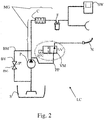
- FIGs. 1 - 4 show schematically preferred embodiments of the present invention
- figure 4 shows a scheme with a an auxiliary oil circuit dedicated to the piston cooling a main oil circuit for the remaining engine oil consumers.
- the same reference numerals and letters in the figures designate the same or functionally equivalent parts.
- the term "second element” does not imply the presence of a "first element", first, second, etc... Are used only for improving the clarity of the description and they should not be interpreted in a limiting way.
- a volumetric internal combustion engine as usual, comprises a piston reciprocated with a respective cylinder.
- a lubricating and cooling system is adopted either to cool the pistons or also to lubricate other "oil consumers".
- the piston comprises an inner cooling passage having at least an inlet and an outlet, while a piston nozzle N of the cooling system is arranged in order to hit said inlet, so as to make the oil circulating within the piston inner cooling passage.
- the oil After its work, the oil, as usual, falls in an oil sump S where the oil is collected.
- the oil is immediately sucked to be stored in a separate tank, thus the oil pump sucks the oil from such oil tank instead of from the oil sump.
- An internal combustion engine comprises, as usual, inlet and exhaust valves in order to introduce a fresh charge into the cylinder and to expel exhaust gas after combustion.
- actuation means AM are raised/lowered by actuation means AM, while switching means SW control said actuation means in order to activate, adjust and deactivate an auxiliary strategy, such as an engine brake and/or an internal EGR.
- switching means can control the inlet valve and/or the exhaust valve behaviour according to the strategy implemented.
- a lubricating and cooling oil circuit is indicated in general with the sign LC. It comprises an oil sump S and at least one oil pump P sucking oil from said oil sump to supply two or more engine oil consumers N, SW, including at least
- the circuit LC comprises valve means VM, on/off or proportional type, on said connection pipe PP activated towards a further throttling operation, in order to increase an oil pressure within said rest of the lubricating and cooling oil circuit, when said switching means SW are activated.
- said further throttling operation or said complete shut-off condition is operated at least for the time period strictly necessary to actuate said switching means.
- valve on the connection pipe PP is called "nozzle valve”.
- the oil pump P driven by the engine crankshaft, pressurizes a so-called "main gallery” MG and the several oil consumers are connected to said main gallery MG independently between each another (star scheme).
- the pipe connection PP connects the nozzle to the main gallery, therefore, indirectly to the pump P.
- "the rest" of the lubricating and cooling oil circuit is clear to the skilled person in the art.
- a cooler C is arranged on the main gallery and some consumers are connected to the main gallery through the cooler, while other consumers can be connected directly to the main gallery.
- a filter F is arranged downstream of the cooler C and some consumers can be connected to the main gallery through the series filter-cooler, while others can be connected to the main gallery directly or through the sole cooler. Even if the piston cooling does not need the filtering of the oil being not sensible to impurities and filings, the connection pipe PP can be connected in any manner to the main gallery.
- connection pipe PP is connected directly to the main gallery, namely upstream of the cooler, the cooling effects involve also the nozzle N, by considering that the whole oil fall within the common oil sump S; therefore, the cooler affects the average temperature of the oil.
- the cooler could be associated with the oil sump or could be series connected upstream of the oil pump P in those dry oil lubrication systems or can be associated with the oil tank of the dry oil lubrication systems. It is clear that "upstream” and “downstream” are referred to the oil circulation.
- the nozzle for cooling the engine piston could consume till the 50% of the overall oil pumped by the oil pump P, therefore, thanks to the present invention, the pressure within the rest of the oil circuit can be suddenly increased (even doubled), by throttling/shutting-off the nozzle. This lead to a reduced sizing of the oil pump P with the appreciable consequence of fuel consumption savings.
- the nozzle valve can restore a previous opening condition, by restoring the nominal oil flow towards the nozzle N.
- the increasing of throttling or the complete closing (shut off) condition of the connection pipe PP has preferably a short duration, under 1 second and approximately between 0.3 and 1 second, that is considered to be sufficient to operate the switching means SW.
- This short time period does not affect the overall piston temperature, whose dynamic is really slow with respect to the activation/deactivation time duration of the switching means.
- shut-off or the increase of the throttling condition is function of the activation of the switching means cooperating with the command means commanding the raising/lowering at least of a cylinder valve: inlet or exhaust according to the auxiliary command strategy implemented.
- the nozzle valve is sufficiently fast in order to induce the required main gallery pressurization for the operation of the switching means.
- the implementation of a proportional nozzle valve instead of an on/off nozzle valve permits also to adjust the oil flow towards the nozzle according to the load and speed of the engine as disclosed in US5220891 .
- the engine brake or the internal EGR are usually activated not coming by the maximum engine speed/load, but from a low-intermediate engine operating point. Therefore, any further throttling of the connection pipe PP does not start from a completely open condition, but from an intermediate open condition, by rendering faster the adjustment of the tightening operation, functional to the operation of the switching means SW.
- bypass means BM connected immediately upstream and downstream of the pump P.
- bypass means comprise a second proportional valve BV that can be controlled by elaborating means EDC in order to control the amount of recirculated oil flow and indirectly to control the main gallery pressurization.
- control means can control the nozzle valve
- the oil pump could also be a variable pump and, as described above can be controlled in coordination with the operation of the nozzle valve VM.
- Figure 4 discloses another embodiment that can be combined with the above disclosed and shows another possibility.
- the nozzle N is fed of oil by an auxiliary pump AP also sucking oil form the common oil sump S or from a common oil tank, in case of dry lubrication system, preferably an electric pump, therefore not driven by the crankshaft.
- An electric pump can be easily controlled, thus, the oil flow can be controlled through the auxiliary pump itself.
- the pump P that in this embodiment is the "main pump”, driven by the crankshaft, can be a fixed pump alone, or a fixed pump coupled with bypass means as disclosed in figure 2 or a variable pump.
- the pipe connection PP between the auxiliary pump AP and the nozzle comprises a valve VM that: in this case it is a diverting valve, namely a 3-way valve capable to alternatively connect the auxiliary pump AP with the nozzle N or with the main gallery MG of the main circuit.
- a valve VM that: in this case it is a diverting valve, namely a 3-way valve capable to alternatively connect the auxiliary pump AP with the nozzle N or with the main gallery MG of the main circuit.
- a main circuit MC where the main pump P is arranged, supplying oil to the valve command means and switching means SW and other oil consumers
- an auxiliary circuit AC where the auxiliary pump AP is arranged, supplying oil to the piston nozzle N.
- the sudden pressure increase within the main gallery MG is achieved by diverting the oil flow from the auxiliary circuit AC to the main one MC.
- the interconnection between the circuits is between the nozzle valve VM and a point of the main circuit preferably upstream of the filter F.
- auxiliary circuit is preferably lacking an own filter being the piston nozzle and the piston cooling gallery not sensitive to impurities.
- the auxiliary circuit can also lack an own cooler, however, for the short time period of activation of the switching means the "auxiliary oil" can be introduced into the main circuit also downstream of the main cooler C for the reasoning discussed above.
- the auxiliary circuit can comprise also an own, separate cooler, or both the circuits, main and auxiliary, can share a common cooler especially if it is associated with a common oil sump S or a common oil tank for those dry oil circuits.
- the auxiliary cooler is refreshed by the ambient air directly or indirectly through an intermediate vectoring medium.
- the auxiliary cooler is a thermal exchanger between the engine oil directed to the piston nozzles and an intermediate vectoring medium circulating in a secondary circuit, where the heat is released to the ambient through the vectoring medium/ambient air exchanger.
- an indirect cooling of the oil directed to the piston nozzle is not mandatory. Therefore, in this case, the main cooler C and the auxiliary cooler, not shown, are thermally independent, so said vectoring medium of the auxiliary cooler is not the engine cooling water.
- the engine oil consumers, served by the main oil circuit, can be any engine oil consumers, served by the main oil circuit.
- the auxiliary pump AP is not electric type, by driven by the engine crankshaft, the auxiliary pump is provided with bypass means connecting the pump inlet with the pump outlet through a controllable auxiliary valve, similar to the bypass valve BV described above and, also in this case, controlled by the control unit EDC.
- the auxiliary circuit comprises an auxiliary pressure sensor AP arranged between on outlet of the auxiliary pump and the piston nozzles N, and the control unit EDC, preferably the engine control unit, controls the auxiliary pump on the basis of a pressure signal generated by the auxiliary pressure sensor.
- the control unit controls the both the pumps so that the oil fed by the auxiliary pump is proportional to the power delivered by the respective combustion engine and/or the oil fed by main pump is proportional to the engine speed/load.
- such controls are actuated by varying the target pressures within the respective main galleries of the main and auxiliary circuits.
- the "oil diversion" from the auxiliary circuit to the main circuit is actuated for a short time when the engine brake function is activated and when the engine braking function is deactivated and in general when a transition between two or more valve operating strategy is varied, for example in order to realize an internal EGR and so on.
- the time interval duration of the oil diversion depends on the dynamics of the organs involved in the operation switching.
- piston nozzles N and the auxiliary pump can be sized and controlled in order to produce a laminar oil jet.
- laminar is well known to the skilled person in the art that knows the Reynolds numbers.
- laminar concept is disclosed also in US2008017139 or in US2004040520 .
- the piston inner cooling passage could be fed of fresh oil intermittently, namely, when the piston is in a proximal position with respect to the corresponding piston nozzle.
- the oil flow can be reduced because independently cooled, and in addition, the oil can be ejected by the nozzle at low pressure, by obtaining at least a near laminar flow. It is well known that with the expression "near laminar flow" is intended Re ⁇ 4000, while a laminar flow is characterized by Re>2300.
- the nozzle inner surfaces are smooth pipes and that, accounting for the oil viscosity and density the laminar jet can be obtained by varying the nozzle opening diameter and the oil velocity, through the Reynolds formula.
- the jet flow becomes even laminar with Re ⁇ 2130.
- This example applies preferably to a 350 kW 6 cylinder engine.
- the oil pressure between 0.1 and 1.5 bar with a preferred interval of 0.1 - 0.5 bar and the nozzle outlet diameters are between 4 - 8 mm.
- a separate cooling circuit is installed for piston cooling with low pressure to minimize pumping energy.
- the cooling oil is at low temperature, preferably at 40° instead of the typical 90 - 100°C. This enables a further reduction of oil flow and/or reduction of oil ageing.
Landscapes
- Engineering & Computer Science (AREA)
- Mechanical Engineering (AREA)
- General Engineering & Computer Science (AREA)
- Chemical & Material Sciences (AREA)
- Combustion & Propulsion (AREA)
- Lubrication Of Internal Combustion Engines (AREA)
Abstract
Description
- The present invention relates to the field of the lubricating and cooling oil circuits for internal combustion engines.
- The engine oil circuit has two different tasks to cool certain components such as the engine pistons, to lubricate other components, such as the bearings, to lubricate and cool other components, such as the turbochargers bearings and to operate further components such as the switching means of the command means of the cylinder valves in order to switch the cylinder valves operation between a normal and at least one auxiliary operation mode.
- The most known auxiliary modes are the engine brake mode, or the internal EGR mode, wherein the engine is fired but a quantity of exhaust gas is retained within the cylinders instead to be expelled from them.
- Such switching means operate thanks to the pressurized oil of the lubricating and cooling oil circuit of the combustion engine.
-
WO2012176736 discloses a variable oil pump and a control system capable to control the variable oil pump in order to increase the oil pressure when necessary included the engine brake mode. - However, the variable oil pumps are expensive and not robust as much as a fixed pump, thus, often a fixed oil pump is preferred.
- According to another solution disclosed in JPH0417708 a fixed oil pump is coupled with bypass means in order to drain the power strictly necessary from the combustion engine.
- However, in both the situations, the oil pump capacity have to be sized for facing the worst condition in which the cylinder valves switching means are activated at full load.
- The main object of the present invention to provide a lubricating and cooling oil circuit for an internal combustion engine capable to implement an oil pump of reduced capacity without compromising the performance of the switching means of the cylinder valve command even at full load.
- The present invention could represent also an alternative solution with respect to known ones.
- The main principle of the invention is to increase throttling or even interrupt the connection between at least one piston oil nozzle and the rest of the lubricating and cooling oil circuit in order to increase the oil pressure within the main gallery of the lubricating and cooling oil circuit when the switching means are activated. In other words, when the driver or the engine control unit of the combustion engine activates/deactivates respectively the engine brake and/or the internal EGR, the switching means command a variation of the cylinder valve behavior, namely the rising/lowering angle, thus the oil pressure within the lubricating and cooling oil circuit is suddenly increased by throttling or shutting off the connection between the main gallery of the lubricating and cooling oil circuit and the nozzle producing the oil jet intended to cool the engine pistons.
- According to a preferred embodiment of the invention, the oil flow is interrupted or reduced towards the piston oil nozzles for a short interval strictly necessary to operate said command valve variation. Preferably, such interval have a duration between 0.3 to 1 second and preferably is function of the engine load condition just before the activation/deactivation of at least one auxiliary mode. Examples of switching means for activating auxiliary modes are given in
US4615307 or inUS2014090616 . - These and further objects are achieved by means of the attached claims, which describe preferred embodiments of the invention, forming an integral part of the present description.
- The invention will become fully clear from the following detailed description, given by way of a mere exemplifying and non-limiting example, to be read with reference to the attached drawing figures, wherein
Figs. 1 - 4 show schematically preferred embodiments of the present invention, in particular,figure 4 shows a scheme with a an auxiliary oil circuit dedicated to the piston cooling a main oil circuit for the remaining engine oil consumers. The same reference numerals and letters in the figures designate the same or functionally equivalent parts. According to the present invention, the term "second element" does not imply the presence of a "first element", first, second, etc... Are used only for improving the clarity of the description and they should not be interpreted in a limiting way. - A volumetric internal combustion engine, as usual, comprises a piston reciprocated with a respective cylinder. A lubricating and cooling system is adopted either to cool the pistons or also to lubricate other "oil consumers". The piston comprises an inner cooling passage having at least an inlet and an outlet, while a piston nozzle N of the cooling system is arranged in order to hit said inlet, so as to make the oil circulating within the piston inner cooling passage.
- After its work, the oil, as usual, falls in an oil sump S where the oil is collected. Alternatively, in those dry lubricating systems, the oil is immediately sucked to be stored in a separate tank, thus the oil pump sucks the oil from such oil tank instead of from the oil sump.
- An internal combustion engine, not shown, comprises, as usual, inlet and exhaust valves in order to introduce a fresh charge into the cylinder and to expel exhaust gas after combustion.
- The above valves are raised/lowered by actuation means AM, while switching means SW control said actuation means in order to activate, adjust and deactivate an auxiliary strategy, such as an engine brake and/or an internal EGR. Such switching means can control the inlet valve and/or the exhaust valve behaviour according to the strategy implemented.
- With reference to any of the
figures 1 - 3 , according to the present invention a lubricating and cooling oil circuit is indicated in general with the sign LC. It comprises an oil sump S and at least one oil pump P sucking oil from said oil sump to supply two or more engine oil consumers N, SW, including at least - said switching means SW,
- a nozzle N to produce an oil jet to cool said piston and a connection pipe PP from the nozzle and the rest of the lubricating and cooling oil circuit.
- According to the present invention, the circuit LC comprises valve means VM, on/off or proportional type, on said connection pipe PP activated towards a further throttling operation, in order to increase an oil pressure within said rest of the lubricating and cooling oil circuit, when said switching means SW are activated. Preferably, said further throttling operation or said complete shut-off condition is operated at least for the time period strictly necessary to actuate said switching means.
- In the following, for simplicity, said valve on the connection pipe PP is called "nozzle valve".
- It is well known that the oil pump P, driven by the engine crankshaft, pressurizes a so-called "main gallery" MG and the several oil consumers are connected to said main gallery MG independently between each another (star scheme). Also according to the present invention, the pipe connection PP connects the nozzle to the main gallery, therefore, indirectly to the pump P. In this context, "the rest" of the lubricating and cooling oil circuit is clear to the skilled person in the art.
- According to the figures, a cooler C is arranged on the main gallery and some consumers are connected to the main gallery through the cooler, while other consumers can be connected directly to the main gallery.
- According to the figures, a filter F is arranged downstream of the cooler C and some consumers can be connected to the main gallery through the series filter-cooler, while others can be connected to the main gallery directly or through the sole cooler. Even if the piston cooling does not need the filtering of the oil being not sensible to impurities and filings, the connection pipe PP can be connected in any manner to the main gallery.
- It should be note that even if the connection pipe PP is connected directly to the main gallery, namely upstream of the cooler, the cooling effects involve also the nozzle N, by considering that the whole oil fall within the common oil sump S; therefore, the cooler affects the average temperature of the oil.
- According to other embodiments that can be combined with these herewith described, the cooler could be associated with the oil sump or could be series connected upstream of the oil pump P in those dry oil lubrication systems or can be associated with the oil tank of the dry oil lubrication systems. It is clear that "upstream" and "downstream" are referred to the oil circulation.
- It should be considered that the nozzle for cooling the engine piston could consume till the 50% of the overall oil pumped by the oil pump P, therefore, thanks to the present invention, the pressure within the rest of the oil circuit can be suddenly increased (even doubled), by throttling/shutting-off the nozzle. This lead to a reduced sizing of the oil pump P with the appreciable consequence of fuel consumption savings.
- When the switching of the command means between a normal mode to an engine brake mode or to an internal EGR mode is completed, the nozzle valve can restore a previous opening condition, by restoring the nominal oil flow towards the nozzle N.
- It should be understood that the "nominal" oil flow should not be intended as a fixed value, but it should, in turn, a function of the engine load/speed condition as disclosed in
US5220891 . - Therefore, the increasing of throttling or the complete closing (shut off) condition of the connection pipe PP has preferably a short duration, under 1 second and approximately between 0.3 and 1 second, that is considered to be sufficient to operate the switching means SW. This short time period does not affect the overall piston temperature, whose dynamic is really slow with respect to the activation/deactivation time duration of the switching means.
- It should be noted that in
US2014090616 the command means are continuously variable. The present invention could be effectively combined with the teaching ofUS2014090616 by accompanying the continuously variable valve command means with a continuous variable throttling of the connection pipe PP by increasing the pressure in the rest of the oil circuit only when strictly needed and for the strictly needed pressure increasing. - The concept of "throttling", disclosed in
figure 3 , highlights several degrees of opening/closing of the connection pipe operable with a proportional nozzle valve in comparison with the complete opening and closing conditions obtained by a simpler on/off nozzle valve. Therefore, according to the present invention, the shut-off or the increase of the throttling condition is function of the activation of the switching means cooperating with the command means commanding the raising/lowering at least of a cylinder valve: inlet or exhaust according to the auxiliary command strategy implemented. - It is appreciable that the nozzle valve is sufficiently fast in order to induce the required main gallery pressurization for the operation of the switching means. The implementation of a proportional nozzle valve instead of an on/off nozzle valve permits also to adjust the oil flow towards the nozzle according to the load and speed of the engine as disclosed in
US5220891 . However, the engine brake or the internal EGR are usually activated not coming by the maximum engine speed/load, but from a low-intermediate engine operating point. Therefore, any further throttling of the connection pipe PP does not start from a completely open condition, but from an intermediate open condition, by rendering faster the adjustment of the tightening operation, functional to the operation of the switching means SW. - According to
figure 2 , the fixed oil pump P is coupled with bypass means BM connected immediately upstream and downstream of the pump P. Such bypass means comprise a second proportional valve BV that can be controlled by elaborating means EDC in order to control the amount of recirculated oil flow and indirectly to control the main gallery pressurization. - Therefore, the control means can control the nozzle valve
- VM and the second valve BV in coordination between each other. This embodiment comes from the merge of the schemes of
figures 2 and3 . - The oil pump could also be a variable pump and, as described above can be controlled in coordination with the operation of the nozzle valve VM.
-
Figure 4 discloses another embodiment that can be combined with the above disclosed and shows another possibility. In particular, the nozzle N is fed of oil by an auxiliary pump AP also sucking oil form the common oil sump S or from a common oil tank, in case of dry lubrication system, preferably an electric pump, therefore not driven by the crankshaft. - An electric pump can be easily controlled, thus, the oil flow can be controlled through the auxiliary pump itself.
- The pump P, that in this embodiment is the "main pump", driven by the crankshaft, can be a fixed pump alone, or a fixed pump coupled with bypass means as disclosed in
figure 2 or a variable pump. - The pipe connection PP between the auxiliary pump AP and the nozzle comprises a valve VM that: in this case it is a diverting valve, namely a 3-way valve capable to alternatively connect the auxiliary pump AP with the nozzle N or with the main gallery MG of the main circuit.
- Therefore, two independent circuits are achieved, a main circuit MC, where the main pump P is arranged, supplying oil to the valve command means and switching means SW and other oil consumers, and an auxiliary circuit AC, where the auxiliary pump AP is arranged, supplying oil to the piston nozzle N.
- According to this embodiment, the sudden pressure increase within the main gallery MG is achieved by diverting the oil flow from the auxiliary circuit AC to the main one MC.
- The interconnection between the circuits is between the nozzle valve VM and a point of the main circuit preferably upstream of the filter F.
- Indeed the auxiliary circuit is preferably lacking an own filter being the piston nozzle and the piston cooling gallery not sensitive to impurities.
- The auxiliary circuit can also lack an own cooler, however, for the short time period of activation of the switching means the "auxiliary oil" can be introduced into the main circuit also downstream of the main cooler C for the reasoning discussed above. Anyway, the auxiliary circuit can comprise also an own, separate cooler, or both the circuits, main and auxiliary, can share a common cooler especially if it is associated with a common oil sump S or a common oil tank for those dry oil circuits.
- Preferably, the auxiliary cooler, not shown, is refreshed by the ambient air directly or indirectly through an intermediate vectoring medium. Preferably, the auxiliary cooler is a thermal exchanger between the engine oil directed to the piston nozzles and an intermediate vectoring medium circulating in a secondary circuit, where the heat is released to the ambient through the vectoring medium/ambient air exchanger. However, an indirect cooling of the oil directed to the piston nozzle is not mandatory. Therefore, in this case, the main cooler C and the auxiliary cooler, not shown, are thermally independent, so said vectoring medium of the auxiliary cooler is not the engine cooling water.
- The engine oil consumers, served by the main oil circuit, can be
- crankshaft bearings CR,
- camshaft bearings (CM) and rocker arms (RA),
- engine brake organs (EB) and eventually idler gears
- air compressor bearings
- turbocharger bearings
- gears
- PTO (Power Take Off).
- In case the auxiliary pump AP is not electric type, by driven by the engine crankshaft, the auxiliary pump is provided with bypass means connecting the pump inlet with the pump outlet through a controllable auxiliary valve, similar to the bypass valve BV described above and, also in this case, controlled by the control unit EDC.
- According to another preferred embodiment that can be combined with the above ones, the auxiliary circuit comprises an auxiliary pressure sensor AP arranged between on outlet of the auxiliary pump and the piston nozzles N, and the control unit EDC, preferably the engine control unit, controls the auxiliary pump on the basis of a pressure signal generated by the auxiliary pressure sensor. According to another preferred embodiment of the invention, even combinable with the others herewith described, the control unit controls the both the pumps so that the oil fed by the auxiliary pump is proportional to the power delivered by the respective combustion engine and/or the oil fed by main pump is proportional to the engine speed/load.
- Preferably, such controls are actuated by varying the target pressures within the respective main galleries of the main and auxiliary circuits.
- Also the "oil diversion" from the auxiliary circuit to the main circuit is actuated for a short time when the engine brake function is activated and when the engine braking function is deactivated and in general when a transition between two or more valve operating strategy is varied, for example in order to realize an internal EGR and so on.
- The time interval duration of the oil diversion depends on the dynamics of the organs involved in the operation switching.
- In addition, the piston nozzles N and the auxiliary pump can be sized and controlled in order to produce a laminar oil jet. The meaning of "laminar" is well known to the skilled person in the art that knows the Reynolds numbers. Furthermore, the "laminar" concept is disclosed also in
US2008017139 or inUS2004040520 . - If the oil jets are maintained at laminar (or near laminar) conditions, the piston inner cooling passage could be fed of fresh oil intermittently, namely, when the piston is in a proximal position with respect to the corresponding piston nozzle.
- The delivery of piston cooling oil at very low oil pressure implies low pumping power, while ensuring a sufficient quantity of oil reaching the piston gallery.
- Therefore, the oil flow can be reduced because independently cooled, and in addition, the oil can be ejected by the nozzle at low pressure, by obtaining at least a near laminar flow. It is well known that with the expression "near laminar flow" is intended Re<4000, while a laminar flow is characterized by Re>2300.
- It is clear that, in order to maintain the oil pressure low, the nozzle inner surfaces are smooth pipes and that, accounting for the oil viscosity and density the laminar jet can be obtained by varying the nozzle opening diameter and the oil velocity, through the Reynolds formula.
- For example, with an oil pressure of about 0.1 bar at the nozzle and with a nozzle outlet diameter of about 6 mm, the jet flow becomes even laminar with Re < 2130.
- This means that there is minimal spray dispersion and the target, namely the piston cooling inlet opening (or bore), could be hit with a high efficiency. On the other side, this means to reduce drastically the energy needed to pump the oil.
- This example, applies preferably to a 350 kW 6 cylinder engine.
- In general, it is preferred to maintain the oil pressure between 0.1 and 1.5 bar with a preferred interval of 0.1 - 0.5 bar and the nozzle outlet diameters are between 4 - 8 mm.
- By means of this last embodiment, a number of further advantages are achieved. A separate cooling circuit is installed for piston cooling with low pressure to minimize pumping energy. The cooling oil is at low temperature, preferably at 40° instead of the typical 90 - 100°C. This enables a further reduction of oil flow and/or reduction of oil ageing.
- Many changes, modifications, variations and other uses and applications of the subject invention will become apparent to those skilled in the art after considering the specification and the accompanying drawings, which disclose preferred embodiments thereof. All such changes, modifications, variations and other uses and applications which do not depart from the scope of the invention are deemed to be covered by this invention.
- It should be understood that all the single features and/or embodiments can be combined between each other. In addition, the features disclosed in the prior art background are introduced only in order to better understand the invention and not as a declaration about the existence of known prior art. Therefore, also the features described in the prior art background can be considered in combination with those mentioned in each embodiment of the detailed description.
- Further implementation details will not be described, as the man skilled in the art is able to carry out the invention starting from the teaching of the above description.
Claims (17)
- Lubricating and cooling oil circuit (LC) of an internal combustion engine comprising at least one cylinder/piston, inlet and exhaust valves and actuation means of the inlet and exhaust valves and switching means for controlling said actuation means in order to activate/deactivate an auxiliary valve control strategy, such as an engine brake and/or an internal EGR, the oil circuit (LC) comprising a main gallery (MG) to supply two or more engine oil consumers including said switching means (SW) and a nozzle (N) to produce an oil jet to cool said piston, wherein the oil circuit comprises a connection pipe (PP) to supply said nozzle and valve means (VM) on said connection pipe (PP) configured to increase throttling or shut-off of said connection pipe, in order to increase an oil pressure within said main gallery when said switching means are activated.
- Circuit according to claim 1, wherein control means (EDC) are configured to control said valve means (VM).
- Circuit according to any of the previous claims, wherein said throttling increase or shut-off condition is maintained for a time period sufficient to the operation of such switching means (SW) in controlling said actuation means.
- Circuit according to claim 3, wherein said time period is about 0.3 - 1 second.
- Circuit according to any of previous claims, further comprising a pump (P) for sucking oil from an oil sump to pressurize said main gallery, wherein said pump (P) is a fixed pump alone, or a fixed pump coupled with relative bypass means (BM) or a variable pump and wherein said control means (EDC) are configured also to control said bypass means or said variable pump as a function of the engine speed and/or load.
- Circuit according to any of previous claims from 1 to 5, wherein said connection pipe (PP) is connected to said main gallery (MG).
- Circuit according to claims 5 or 6, wherein said pump (P) is hereinafter called "main pump" and the circuit further comprises an auxiliary pump (AP), independent from said main pump, feeding oil to said connection pipe (PP), by defining an "auxiliary circuit", separate and independent from said main gallery (MG), and wherein said valve means (VM) are suitable to divert oil pumped from the auxiliary pump (AP) towards said main gallery (MG) by shutting off said nozzle (N), when said switching means are activated.
- Circuit according to claim 7, wherein- the circuit (LC) comprises just one cooler (C) connected downstream of said main gallery and both said main pump and said auxiliary pump suck oil from said oil sump (S) or- the circuit (LC) comprises just one cooler associated with said oil sump (S) and both said main pump and said auxiliary pump suck oil from said oil sump (S) or- the circuit is of the dry type, comprising also an oil tank and just one cooler associated with said oil tank or arranged downstream of said oil tank and both said main pump and said auxiliary pump suck oil from said oil tank or- the circuit comprising two oil coolers, one main cooler arranged downstream of said main pump and one auxiliary cooler arranged downstream of said auxiliary pump.
- Circuit according to claim 8, wherein said auxiliary cooler is refreshed by the ambient air directly or indirectly through an intermediate vectoring medium.
- Circuit according to claim 9, wherein, said vectoring medium is not the engine cooling water.
- Circuit according to any of previous claims, wherein said engine oil consumers, supplied by the main circuit, comprise at lest one of:- crankshaft bearings,- actuation means: camshaft bearings and rocker arms, engine brake organs and eventually idler gears- air compressor bearings and/or turbine bearings- gearshift,- PTO.- said auxiliary pump.
- Circuit according to any of previous claims, further comprising an oil filter (F) arranged downstream of said main gallery (MG).
- Circuit according to claim 8, further comprising an oil filter (F) arranged downstream of said main gallery (MG) and wherein said valve means are suitable to divert oil pumped from the auxiliary pump (AP) towards said main gallery (MG) upstream of said oil filter (F).
- Circuit according to any of the previous claims 7 - 13, wherein said auxiliary oil circuit is not provided of filtering means.
- Circuit according to any of the previous claims 7 - 14, wherein said auxiliary pump (AP) is- driven by the engine crankshaft and is a fixed pump alone, or a fixed pump coupled with relative auxiliary bypass means (BM) or is a variable pump or- electric typeAnd wherein said control means (EDC) are configured also to control said bypass means or said auxiliary variable pump according as a function of the engine speed and/or load.
- Combustion engine comprising a piston reciprocated with a respective cylinder, the piston comprising an inner cooling passage having at least an inlet and an outlet, the engine being provided with a lubricating and cooling oil circuit according to any of previous claims 1 to 15.
- Vehicle provided with the combustion engine of claim 16.
Applications Claiming Priority (1)
| Application Number | Priority Date | Filing Date | Title |
|---|---|---|---|
| ITUB2015A003993A ITUB20153993A1 (en) | 2015-09-29 | 2015-09-29 | LUBRICATION OIL CIRCUIT AND COOLING OF AN INTERNAL COMBUSTION ENGINE |
Publications (2)
| Publication Number | Publication Date |
|---|---|
| EP3150811A1 true EP3150811A1 (en) | 2017-04-05 |
| EP3150811B1 EP3150811B1 (en) | 2019-04-17 |
Family
ID=54884334
Family Applications (1)
| Application Number | Title | Priority Date | Filing Date |
|---|---|---|---|
| EP16191621.8A Active EP3150811B1 (en) | 2015-09-29 | 2016-09-29 | Lubricating and cooling oil circuit for an internal combustion engine |
Country Status (3)
| Country | Link |
|---|---|
| EP (1) | EP3150811B1 (en) |
| ES (1) | ES2733827T3 (en) |
| IT (1) | ITUB20153993A1 (en) |
Cited By (11)
| Publication number | Priority date | Publication date | Assignee | Title |
|---|---|---|---|---|
| IT201800003414A1 (en) * | 2018-03-09 | 2019-09-09 | Fpt Motorenforschung Ag | METHOD OF MANAGING A LUBRICATION OF AN INTERNAL COMBUSTION ENGINE AND INTERNAL COMBUSTION ENGINE IMPLEMENTING THE METHOD |
| WO2020001908A1 (en) | 2018-06-25 | 2020-01-02 | Vhit S.P.A. Societa Unipersonal | Multi-purpose hydraulic system |
| WO2020048586A1 (en) * | 2018-09-04 | 2020-03-12 | Volvo Truck Corporation | Engine system and method for a vehicle |
| CN111237042A (en) * | 2018-11-29 | 2020-06-05 | 潍柴动力股份有限公司 | A lubricating system for piston cooling, engine and body thereof |
| EP3516180A4 (en) * | 2016-10-31 | 2020-06-17 | Cummins Inc. | REDUCED PARASITE LUBRICATION SYSTEM |
| CN111441842A (en) * | 2020-05-08 | 2020-07-24 | 河北工业大学 | Engine oil system with modularized piston oil injection |
| GB2591272A (en) * | 2020-01-23 | 2021-07-28 | Daimler Ag | Internal combustion engine for a vehicle |
| WO2021167801A1 (en) * | 2020-02-21 | 2021-08-26 | Cummins Inc. | Maintaining oil pressure during cylinder deactivation operation |
| CN113550808A (en) * | 2021-08-18 | 2021-10-26 | 河南柴油机重工有限责任公司 | A throttling control lubrication system |
| CN113847140A (en) * | 2021-09-08 | 2021-12-28 | 东风汽车集团股份有限公司 | Range extender lubricating and cooling system, hybrid electric vehicle and control method |
| CN116398268A (en) * | 2023-05-09 | 2023-07-07 | 长城汽车股份有限公司 | Engine oil cooling system, method and engine |
Citations (11)
| Publication number | Priority date | Publication date | Assignee | Title |
|---|---|---|---|---|
| US3065743A (en) * | 1961-02-09 | 1962-11-27 | Int Harvester Co | Internal combustion engine lubricating system and temperature regulating means for the pistons thereof |
| US4615307A (en) | 1984-03-29 | 1986-10-07 | Aisin Seiki Kabushiki Kaisha | Hydraulic valve lifter for variable displacement engine |
| GB2198474A (en) * | 1986-11-12 | 1988-06-15 | Honda Motor Co Ltd | Hydraulic actuation of an engine valve operation timing changing device |
| US5220891A (en) | 1991-03-15 | 1993-06-22 | Nissan Motor Co., Ltd. | Variable cam engine |
| US20040040520A1 (en) | 2002-09-02 | 2004-03-04 | Christophe Bontaz | Multiple spray engine cooling nozzle and engines equipped with such nozzles |
| US20050061289A1 (en) * | 2003-09-18 | 2005-03-24 | Plenzler Jeremy M. | Engine oil system with oil pressure regulator to increase cam phaser oil pressure |
| US20080017139A1 (en) | 2004-11-30 | 2008-01-24 | Wolfgang Issler | Piston Spray Nozzle |
| JP2010001750A (en) * | 2008-06-18 | 2010-01-07 | Toyota Motor Corp | Control device for internal combustion engine |
| WO2012176736A1 (en) | 2011-06-24 | 2012-12-27 | いすゞ自動車株式会社 | Internal combustion engine, and method of controlling same |
| US20140090616A1 (en) | 2012-09-28 | 2014-04-03 | Hyundai Motor Company | Cylinder air volume difference adjuster and continuous variable valve lifter including the same |
| WO2014156012A1 (en) * | 2013-03-29 | 2014-10-02 | マツダ株式会社 | Control device for multi-cylinder engine |
-
2015
- 2015-09-29 IT ITUB2015A003993A patent/ITUB20153993A1/en unknown
-
2016
- 2016-09-29 ES ES16191621T patent/ES2733827T3/en active Active
- 2016-09-29 EP EP16191621.8A patent/EP3150811B1/en active Active
Patent Citations (11)
| Publication number | Priority date | Publication date | Assignee | Title |
|---|---|---|---|---|
| US3065743A (en) * | 1961-02-09 | 1962-11-27 | Int Harvester Co | Internal combustion engine lubricating system and temperature regulating means for the pistons thereof |
| US4615307A (en) | 1984-03-29 | 1986-10-07 | Aisin Seiki Kabushiki Kaisha | Hydraulic valve lifter for variable displacement engine |
| GB2198474A (en) * | 1986-11-12 | 1988-06-15 | Honda Motor Co Ltd | Hydraulic actuation of an engine valve operation timing changing device |
| US5220891A (en) | 1991-03-15 | 1993-06-22 | Nissan Motor Co., Ltd. | Variable cam engine |
| US20040040520A1 (en) | 2002-09-02 | 2004-03-04 | Christophe Bontaz | Multiple spray engine cooling nozzle and engines equipped with such nozzles |
| US20050061289A1 (en) * | 2003-09-18 | 2005-03-24 | Plenzler Jeremy M. | Engine oil system with oil pressure regulator to increase cam phaser oil pressure |
| US20080017139A1 (en) | 2004-11-30 | 2008-01-24 | Wolfgang Issler | Piston Spray Nozzle |
| JP2010001750A (en) * | 2008-06-18 | 2010-01-07 | Toyota Motor Corp | Control device for internal combustion engine |
| WO2012176736A1 (en) | 2011-06-24 | 2012-12-27 | いすゞ自動車株式会社 | Internal combustion engine, and method of controlling same |
| US20140090616A1 (en) | 2012-09-28 | 2014-04-03 | Hyundai Motor Company | Cylinder air volume difference adjuster and continuous variable valve lifter including the same |
| WO2014156012A1 (en) * | 2013-03-29 | 2014-10-02 | マツダ株式会社 | Control device for multi-cylinder engine |
Cited By (19)
| Publication number | Priority date | Publication date | Assignee | Title |
|---|---|---|---|---|
| EP3516180A4 (en) * | 2016-10-31 | 2020-06-17 | Cummins Inc. | REDUCED PARASITE LUBRICATION SYSTEM |
| US12163449B2 (en) | 2016-10-31 | 2024-12-10 | Cummins Inc. | Reduced parasitic lube system |
| US11719139B2 (en) | 2016-10-31 | 2023-08-08 | Cummins Inc. | Reduced parasitic lube system |
| EP3536918A1 (en) | 2018-03-09 | 2019-09-11 | FPT Motorenforschung AG | Management method of an internal combustion engine lubrication and internal combustion engine implementing the method |
| IT201800003414A1 (en) * | 2018-03-09 | 2019-09-09 | Fpt Motorenforschung Ag | METHOD OF MANAGING A LUBRICATION OF AN INTERNAL COMBUSTION ENGINE AND INTERNAL COMBUSTION ENGINE IMPLEMENTING THE METHOD |
| WO2020001908A1 (en) | 2018-06-25 | 2020-01-02 | Vhit S.P.A. Societa Unipersonal | Multi-purpose hydraulic system |
| US11603778B2 (en) | 2018-09-04 | 2023-03-14 | Volvo Truck Corporation | Engine system and method for a vehicle |
| WO2020048586A1 (en) * | 2018-09-04 | 2020-03-12 | Volvo Truck Corporation | Engine system and method for a vehicle |
| CN111237042A (en) * | 2018-11-29 | 2020-06-05 | 潍柴动力股份有限公司 | A lubricating system for piston cooling, engine and body thereof |
| GB2591272A (en) * | 2020-01-23 | 2021-07-28 | Daimler Ag | Internal combustion engine for a vehicle |
| WO2021167801A1 (en) * | 2020-02-21 | 2021-08-26 | Cummins Inc. | Maintaining oil pressure during cylinder deactivation operation |
| CN116034220A (en) * | 2020-02-21 | 2023-04-28 | 卡明斯公司 | Maintains oil pressure during cylinder deactivation operation |
| US12264604B2 (en) | 2020-02-21 | 2025-04-01 | Cummins Inc. | Maintaining oil pressure during cylinder deactivation operation |
| CN111441842A (en) * | 2020-05-08 | 2020-07-24 | 河北工业大学 | Engine oil system with modularized piston oil injection |
| CN113550808B (en) * | 2021-08-18 | 2022-11-29 | 河南柴油机重工有限责任公司 | Throttle control lubricating system |
| CN113550808A (en) * | 2021-08-18 | 2021-10-26 | 河南柴油机重工有限责任公司 | A throttling control lubrication system |
| CN113847140B (en) * | 2021-09-08 | 2023-03-03 | 东风汽车集团股份有限公司 | Range extender lubricating and cooling system, hybrid electric vehicle and control method |
| CN113847140A (en) * | 2021-09-08 | 2021-12-28 | 东风汽车集团股份有限公司 | Range extender lubricating and cooling system, hybrid electric vehicle and control method |
| CN116398268A (en) * | 2023-05-09 | 2023-07-07 | 长城汽车股份有限公司 | Engine oil cooling system, method and engine |
Also Published As
| Publication number | Publication date |
|---|---|
| ES2733827T3 (en) | 2019-12-03 |
| EP3150811B1 (en) | 2019-04-17 |
| ITUB20153993A1 (en) | 2017-03-29 |
Similar Documents
| Publication | Publication Date | Title |
|---|---|---|
| EP3150811B1 (en) | Lubricating and cooling oil circuit for an internal combustion engine | |
| US9617923B2 (en) | Engine fuel control system | |
| US9512783B2 (en) | Aircraft fuel system | |
| CN102575587B (en) | Fuel supply circuits for aeroengines | |
| JP5920483B2 (en) | Oil supply device for internal combustion engine | |
| US7287368B2 (en) | Fluid system | |
| RU2015110012A (en) | METHOD (OPTIONS) AND SYSTEM OF SUPPLY OF OIL TO THE INTERNAL COMBUSTION ENGINE | |
| US20140290266A1 (en) | Fuel and actuation system for gas turbine engine | |
| CN204060840U (en) | Engine lubrication system | |
| CN107524491B (en) | Engine assembly | |
| CN107662696A (en) | Method for the cooling system of operating ship | |
| US9970347B2 (en) | Cooling system having pulsed fan control | |
| EP3150821B1 (en) | Internal combustion engine provided with a piston cooling system | |
| KR101209748B1 (en) | output pressure control system of oil pump | |
| US20180058277A1 (en) | Method and apparatus to regulate oil pressure via controllable piston cooling jets | |
| EP3034839B2 (en) | Means and arrangement for fuel icing protection | |
| CN102278165B (en) | Oil supply system for an internal combustion engine | |
| US8438848B2 (en) | Engine with turbocharger and EGR | |
| WO2013156519A1 (en) | Method for controlling a piston cooling circuit of an internal combustion engine of an industrial vehicle | |
| US12264604B2 (en) | Maintaining oil pressure during cylinder deactivation operation | |
| US10774726B2 (en) | Valve for adjusting a cooling fluid flow for piston cooling | |
| US9828908B2 (en) | Device for internal cooling and pressurization of rotary engine | |
| EP3382170B1 (en) | Lubricating and cooling system for an internal combustion engine | |
| JP2015061980A (en) | Gas burning engine | |
| JP4649368B2 (en) | Cooling device for internal combustion engine |
Legal Events
| Date | Code | Title | Description |
|---|---|---|---|
| PUAI | Public reference made under article 153(3) epc to a published international application that has entered the european phase |
Free format text: ORIGINAL CODE: 0009012 |
|
| STAA | Information on the status of an ep patent application or granted ep patent |
Free format text: STATUS: THE APPLICATION HAS BEEN PUBLISHED |
|
| AK | Designated contracting states |
Kind code of ref document: A1 Designated state(s): AL AT BE BG CH CY CZ DE DK EE ES FI FR GB GR HR HU IE IS IT LI LT LU LV MC MK MT NL NO PL PT RO RS SE SI SK SM TR |
|
| AX | Request for extension of the european patent |
Extension state: BA ME |
|
| STAA | Information on the status of an ep patent application or granted ep patent |
Free format text: STATUS: REQUEST FOR EXAMINATION WAS MADE |
|
| 17P | Request for examination filed |
Effective date: 20171005 |
|
| RBV | Designated contracting states (corrected) |
Designated state(s): AL AT BE BG CH CY CZ DE DK EE ES FI FR GB GR HR HU IE IS IT LI LT LU LV MC MK MT NL NO PL PT RO RS SE SI SK SM TR |
|
| STAA | Information on the status of an ep patent application or granted ep patent |
Free format text: STATUS: EXAMINATION IS IN PROGRESS |
|
| 17Q | First examination report despatched |
Effective date: 20180306 |
|
| GRAP | Despatch of communication of intention to grant a patent |
Free format text: ORIGINAL CODE: EPIDOSNIGR1 |
|
| STAA | Information on the status of an ep patent application or granted ep patent |
Free format text: STATUS: GRANT OF PATENT IS INTENDED |
|
| INTG | Intention to grant announced |
Effective date: 20181114 |
|
| GRAS | Grant fee paid |
Free format text: ORIGINAL CODE: EPIDOSNIGR3 |
|
| GRAA | (expected) grant |
Free format text: ORIGINAL CODE: 0009210 |
|
| STAA | Information on the status of an ep patent application or granted ep patent |
Free format text: STATUS: THE PATENT HAS BEEN GRANTED |
|
| AK | Designated contracting states |
Kind code of ref document: B1 Designated state(s): AL AT BE BG CH CY CZ DE DK EE ES FI FR GB GR HR HU IE IS IT LI LT LU LV MC MK MT NL NO PL PT RO RS SE SI SK SM TR |
|
| REG | Reference to a national code |
Ref country code: GB Ref legal event code: FG4D |
|
| REG | Reference to a national code |
Ref country code: CH Ref legal event code: EP |
|
| REG | Reference to a national code |
Ref country code: DE Ref legal event code: R096 Ref document number: 602016012491 Country of ref document: DE |
|
| REG | Reference to a national code |
Ref country code: AT Ref legal event code: REF Ref document number: 1121783 Country of ref document: AT Kind code of ref document: T Effective date: 20190515 Ref country code: IE Ref legal event code: FG4D |
|
| REG | Reference to a national code |
Ref country code: NL Ref legal event code: FP |
|
| REG | Reference to a national code |
Ref country code: CH Ref legal event code: NV Representative=s name: HEPP WENGER RYFFEL AG, CH |
|
| REG | Reference to a national code |
Ref country code: SE Ref legal event code: TRGR |
|
| REG | Reference to a national code |
Ref country code: LT Ref legal event code: MG4D |
|
| PG25 | Lapsed in a contracting state [announced via postgrant information from national office to epo] |
Ref country code: LT Free format text: LAPSE BECAUSE OF FAILURE TO SUBMIT A TRANSLATION OF THE DESCRIPTION OR TO PAY THE FEE WITHIN THE PRESCRIBED TIME-LIMIT Effective date: 20190417 Ref country code: FI Free format text: LAPSE BECAUSE OF FAILURE TO SUBMIT A TRANSLATION OF THE DESCRIPTION OR TO PAY THE FEE WITHIN THE PRESCRIBED TIME-LIMIT Effective date: 20190417 Ref country code: AL Free format text: LAPSE BECAUSE OF FAILURE TO SUBMIT A TRANSLATION OF THE DESCRIPTION OR TO PAY THE FEE WITHIN THE PRESCRIBED TIME-LIMIT Effective date: 20190417 Ref country code: HR Free format text: LAPSE BECAUSE OF FAILURE TO SUBMIT A TRANSLATION OF THE DESCRIPTION OR TO PAY THE FEE WITHIN THE PRESCRIBED TIME-LIMIT Effective date: 20190417 Ref country code: PT Free format text: LAPSE BECAUSE OF FAILURE TO SUBMIT A TRANSLATION OF THE DESCRIPTION OR TO PAY THE FEE WITHIN THE PRESCRIBED TIME-LIMIT Effective date: 20190817 Ref country code: NO Free format text: LAPSE BECAUSE OF FAILURE TO SUBMIT A TRANSLATION OF THE DESCRIPTION OR TO PAY THE FEE WITHIN THE PRESCRIBED TIME-LIMIT Effective date: 20190717 |
|
| PG25 | Lapsed in a contracting state [announced via postgrant information from national office to epo] |
Ref country code: GR Free format text: LAPSE BECAUSE OF FAILURE TO SUBMIT A TRANSLATION OF THE DESCRIPTION OR TO PAY THE FEE WITHIN THE PRESCRIBED TIME-LIMIT Effective date: 20190718 Ref country code: PL Free format text: LAPSE BECAUSE OF FAILURE TO SUBMIT A TRANSLATION OF THE DESCRIPTION OR TO PAY THE FEE WITHIN THE PRESCRIBED TIME-LIMIT Effective date: 20190417 Ref country code: LV Free format text: LAPSE BECAUSE OF FAILURE TO SUBMIT A TRANSLATION OF THE DESCRIPTION OR TO PAY THE FEE WITHIN THE PRESCRIBED TIME-LIMIT Effective date: 20190417 Ref country code: RS Free format text: LAPSE BECAUSE OF FAILURE TO SUBMIT A TRANSLATION OF THE DESCRIPTION OR TO PAY THE FEE WITHIN THE PRESCRIBED TIME-LIMIT Effective date: 20190417 Ref country code: BG Free format text: LAPSE BECAUSE OF FAILURE TO SUBMIT A TRANSLATION OF THE DESCRIPTION OR TO PAY THE FEE WITHIN THE PRESCRIBED TIME-LIMIT Effective date: 20190717 |
|
| REG | Reference to a national code |
Ref country code: ES Ref legal event code: FG2A Ref document number: 2733827 Country of ref document: ES Kind code of ref document: T3 Effective date: 20191203 |
|
| REG | Reference to a national code |
Ref country code: AT Ref legal event code: MK05 Ref document number: 1121783 Country of ref document: AT Kind code of ref document: T Effective date: 20190417 |
|
| PG25 | Lapsed in a contracting state [announced via postgrant information from national office to epo] |
Ref country code: IS Free format text: LAPSE BECAUSE OF FAILURE TO SUBMIT A TRANSLATION OF THE DESCRIPTION OR TO PAY THE FEE WITHIN THE PRESCRIBED TIME-LIMIT Effective date: 20190817 |
|
| REG | Reference to a national code |
Ref country code: DE Ref legal event code: R097 Ref document number: 602016012491 Country of ref document: DE |
|
| PG25 | Lapsed in a contracting state [announced via postgrant information from national office to epo] |
Ref country code: DK Free format text: LAPSE BECAUSE OF FAILURE TO SUBMIT A TRANSLATION OF THE DESCRIPTION OR TO PAY THE FEE WITHIN THE PRESCRIBED TIME-LIMIT Effective date: 20190417 Ref country code: EE Free format text: LAPSE BECAUSE OF FAILURE TO SUBMIT A TRANSLATION OF THE DESCRIPTION OR TO PAY THE FEE WITHIN THE PRESCRIBED TIME-LIMIT Effective date: 20190417 Ref country code: AT Free format text: LAPSE BECAUSE OF FAILURE TO SUBMIT A TRANSLATION OF THE DESCRIPTION OR TO PAY THE FEE WITHIN THE PRESCRIBED TIME-LIMIT Effective date: 20190417 Ref country code: CZ Free format text: LAPSE BECAUSE OF FAILURE TO SUBMIT A TRANSLATION OF THE DESCRIPTION OR TO PAY THE FEE WITHIN THE PRESCRIBED TIME-LIMIT Effective date: 20190417 Ref country code: RO Free format text: LAPSE BECAUSE OF FAILURE TO SUBMIT A TRANSLATION OF THE DESCRIPTION OR TO PAY THE FEE WITHIN THE PRESCRIBED TIME-LIMIT Effective date: 20190417 Ref country code: SK Free format text: LAPSE BECAUSE OF FAILURE TO SUBMIT A TRANSLATION OF THE DESCRIPTION OR TO PAY THE FEE WITHIN THE PRESCRIBED TIME-LIMIT Effective date: 20190417 |
|
| PLBE | No opposition filed within time limit |
Free format text: ORIGINAL CODE: 0009261 |
|
| STAA | Information on the status of an ep patent application or granted ep patent |
Free format text: STATUS: NO OPPOSITION FILED WITHIN TIME LIMIT |
|
| PG25 | Lapsed in a contracting state [announced via postgrant information from national office to epo] |
Ref country code: SM Free format text: LAPSE BECAUSE OF FAILURE TO SUBMIT A TRANSLATION OF THE DESCRIPTION OR TO PAY THE FEE WITHIN THE PRESCRIBED TIME-LIMIT Effective date: 20190417 |
|
| 26N | No opposition filed |
Effective date: 20200120 |
|
| PG25 | Lapsed in a contracting state [announced via postgrant information from national office to epo] |
Ref country code: TR Free format text: LAPSE BECAUSE OF FAILURE TO SUBMIT A TRANSLATION OF THE DESCRIPTION OR TO PAY THE FEE WITHIN THE PRESCRIBED TIME-LIMIT Effective date: 20190417 |
|
| PG25 | Lapsed in a contracting state [announced via postgrant information from national office to epo] |
Ref country code: MC Free format text: LAPSE BECAUSE OF FAILURE TO SUBMIT A TRANSLATION OF THE DESCRIPTION OR TO PAY THE FEE WITHIN THE PRESCRIBED TIME-LIMIT Effective date: 20190417 Ref country code: SI Free format text: LAPSE BECAUSE OF FAILURE TO SUBMIT A TRANSLATION OF THE DESCRIPTION OR TO PAY THE FEE WITHIN THE PRESCRIBED TIME-LIMIT Effective date: 20190417 |
|
| PG25 | Lapsed in a contracting state [announced via postgrant information from national office to epo] |
Ref country code: IE Free format text: LAPSE BECAUSE OF NON-PAYMENT OF DUE FEES Effective date: 20190929 Ref country code: LU Free format text: LAPSE BECAUSE OF NON-PAYMENT OF DUE FEES Effective date: 20190929 |
|
| REG | Reference to a national code |
Ref country code: BE Ref legal event code: MM Effective date: 20190930 |
|
| PG25 | Lapsed in a contracting state [announced via postgrant information from national office to epo] |
Ref country code: BE Free format text: LAPSE BECAUSE OF NON-PAYMENT OF DUE FEES Effective date: 20190930 |
|
| PG25 | Lapsed in a contracting state [announced via postgrant information from national office to epo] |
Ref country code: CY Free format text: LAPSE BECAUSE OF FAILURE TO SUBMIT A TRANSLATION OF THE DESCRIPTION OR TO PAY THE FEE WITHIN THE PRESCRIBED TIME-LIMIT Effective date: 20190417 |
|
| PG25 | Lapsed in a contracting state [announced via postgrant information from national office to epo] |
Ref country code: HU Free format text: LAPSE BECAUSE OF FAILURE TO SUBMIT A TRANSLATION OF THE DESCRIPTION OR TO PAY THE FEE WITHIN THE PRESCRIBED TIME-LIMIT; INVALID AB INITIO Effective date: 20160929 Ref country code: MT Free format text: LAPSE BECAUSE OF FAILURE TO SUBMIT A TRANSLATION OF THE DESCRIPTION OR TO PAY THE FEE WITHIN THE PRESCRIBED TIME-LIMIT Effective date: 20190417 |
|
| PG25 | Lapsed in a contracting state [announced via postgrant information from national office to epo] |
Ref country code: MK Free format text: LAPSE BECAUSE OF FAILURE TO SUBMIT A TRANSLATION OF THE DESCRIPTION OR TO PAY THE FEE WITHIN THE PRESCRIBED TIME-LIMIT Effective date: 20190417 |
|
| P01 | Opt-out of the competence of the unified patent court (upc) registered |
Effective date: 20230519 |
|
| REG | Reference to a national code |
Ref country code: DE Ref legal event code: R082 Ref document number: 602016012491 Country of ref document: DE Representative=s name: TER MEER STEINMEISTER & PARTNER PATENTANWAELTE, DE |
|
| REG | Reference to a national code |
Ref country code: CH Ref legal event code: U11 Free format text: ST27 STATUS EVENT CODE: U-0-0-U10-U11 (AS PROVIDED BY THE NATIONAL OFFICE) Effective date: 20251001 |
|
| PGFP | Annual fee paid to national office [announced via postgrant information from national office to epo] |
Ref country code: DE Payment date: 20250926 Year of fee payment: 10 |
|
| PGFP | Annual fee paid to national office [announced via postgrant information from national office to epo] |
Ref country code: IT Payment date: 20250909 Year of fee payment: 10 Ref country code: NL Payment date: 20250925 Year of fee payment: 10 |
|
| PGFP | Annual fee paid to national office [announced via postgrant information from national office to epo] |
Ref country code: GB Payment date: 20250923 Year of fee payment: 10 |
|
| PGFP | Annual fee paid to national office [announced via postgrant information from national office to epo] |
Ref country code: FR Payment date: 20250925 Year of fee payment: 10 |
|
| PGFP | Annual fee paid to national office [announced via postgrant information from national office to epo] |
Ref country code: SE Payment date: 20250924 Year of fee payment: 10 |
|
| PGFP | Annual fee paid to national office [announced via postgrant information from national office to epo] |
Ref country code: CH Payment date: 20251001 Year of fee payment: 10 |
|
| PGFP | Annual fee paid to national office [announced via postgrant information from national office to epo] |
Ref country code: ES Payment date: 20251015 Year of fee payment: 10 |