EP3150807A1 - Trailing edge core compartment vent for an aircraft engine - Google Patents
Trailing edge core compartment vent for an aircraft engine Download PDFInfo
- Publication number
- EP3150807A1 EP3150807A1 EP16177843.6A EP16177843A EP3150807A1 EP 3150807 A1 EP3150807 A1 EP 3150807A1 EP 16177843 A EP16177843 A EP 16177843A EP 3150807 A1 EP3150807 A1 EP 3150807A1
- Authority
- EP
- European Patent Office
- Prior art keywords
- core
- engine
- cowl
- nozzle
- terminus
- Prior art date
- Legal status (The legal status is an assumption and is not a legal conclusion. Google has not performed a legal analysis and makes no representation as to the accuracy of the status listed.)
- Granted
Links
Images



Classifications
-
- B—PERFORMING OPERATIONS; TRANSPORTING
- B64—AIRCRAFT; AVIATION; COSMONAUTICS
- B64D—EQUIPMENT FOR FITTING IN OR TO AIRCRAFT; FLIGHT SUITS; PARACHUTES; ARRANGEMENT OR MOUNTING OF POWER PLANTS OR PROPULSION TRANSMISSIONS IN AIRCRAFT
- B64D33/00—Arrangement in aircraft of power plant parts or auxiliaries not otherwise provided for
- B64D33/04—Arrangement in aircraft of power plant parts or auxiliaries not otherwise provided for of exhaust outlets or jet pipes
-
- F—MECHANICAL ENGINEERING; LIGHTING; HEATING; WEAPONS; BLASTING
- F01—MACHINES OR ENGINES IN GENERAL; ENGINE PLANTS IN GENERAL; STEAM ENGINES
- F01D—NON-POSITIVE DISPLACEMENT MACHINES OR ENGINES, e.g. STEAM TURBINES
- F01D25/00—Component parts, details, or accessories, not provided for in, or of interest apart from, other groups
- F01D25/24—Casings; Casing parts, e.g. diaphragms, casing fastenings
- F01D25/26—Double casings; Measures against temperature strain in casings
-
- F—MECHANICAL ENGINEERING; LIGHTING; HEATING; WEAPONS; BLASTING
- F02—COMBUSTION ENGINES; HOT-GAS OR COMBUSTION-PRODUCT ENGINE PLANTS
- F02K—JET-PROPULSION PLANTS
- F02K1/00—Plants characterised by the form or arrangement of the jet pipe or nozzle; Jet pipes or nozzles peculiar thereto
-
- B—PERFORMING OPERATIONS; TRANSPORTING
- B64—AIRCRAFT; AVIATION; COSMONAUTICS
- B64D—EQUIPMENT FOR FITTING IN OR TO AIRCRAFT; FLIGHT SUITS; PARACHUTES; ARRANGEMENT OR MOUNTING OF POWER PLANTS OR PROPULSION TRANSMISSIONS IN AIRCRAFT
- B64D27/00—Arrangement or mounting of power plants in aircraft; Aircraft characterised by the type or position of power plants
- B64D27/02—Aircraft characterised by the type or position of power plants
- B64D27/10—Aircraft characterised by the type or position of power plants of gas-turbine type
- B64D27/12—Aircraft characterised by the type or position of power plants of gas-turbine type within, or attached to, wings
-
- B—PERFORMING OPERATIONS; TRANSPORTING
- B64—AIRCRAFT; AVIATION; COSMONAUTICS
- B64D—EQUIPMENT FOR FITTING IN OR TO AIRCRAFT; FLIGHT SUITS; PARACHUTES; ARRANGEMENT OR MOUNTING OF POWER PLANTS OR PROPULSION TRANSMISSIONS IN AIRCRAFT
- B64D29/00—Power-plant nacelles, fairings or cowlings
-
- F—MECHANICAL ENGINEERING; LIGHTING; HEATING; WEAPONS; BLASTING
- F02—COMBUSTION ENGINES; HOT-GAS OR COMBUSTION-PRODUCT ENGINE PLANTS
- F02C—GAS-TURBINE PLANTS; AIR INTAKES FOR JET-PROPULSION PLANTS; CONTROLLING FUEL SUPPLY IN AIR-BREATHING JET-PROPULSION PLANTS
- F02C7/00—Features, components parts, details or accessories, not provided for in, or of interest apart form groups F02C1/00 - F02C6/00; Air intakes for jet-propulsion plants
- F02C7/12—Cooling of plants
- F02C7/16—Cooling of plants characterised by cooling medium
- F02C7/18—Cooling of plants characterised by cooling medium the medium being gaseous, e.g. air
-
- F—MECHANICAL ENGINEERING; LIGHTING; HEATING; WEAPONS; BLASTING
- F02—COMBUSTION ENGINES; HOT-GAS OR COMBUSTION-PRODUCT ENGINE PLANTS
- F02K—JET-PROPULSION PLANTS
- F02K1/00—Plants characterised by the form or arrangement of the jet pipe or nozzle; Jet pipes or nozzles peculiar thereto
- F02K1/06—Varying effective area of jet pipe or nozzle
-
- F—MECHANICAL ENGINEERING; LIGHTING; HEATING; WEAPONS; BLASTING
- F02—COMBUSTION ENGINES; HOT-GAS OR COMBUSTION-PRODUCT ENGINE PLANTS
- F02K—JET-PROPULSION PLANTS
- F02K1/00—Plants characterised by the form or arrangement of the jet pipe or nozzle; Jet pipes or nozzles peculiar thereto
- F02K1/38—Introducing air inside the jet
-
- F—MECHANICAL ENGINEERING; LIGHTING; HEATING; WEAPONS; BLASTING
- F02—COMBUSTION ENGINES; HOT-GAS OR COMBUSTION-PRODUCT ENGINE PLANTS
- F02K—JET-PROPULSION PLANTS
- F02K1/00—Plants characterised by the form or arrangement of the jet pipe or nozzle; Jet pipes or nozzles peculiar thereto
- F02K1/78—Other construction of jet pipes
- F02K1/82—Jet pipe walls, e.g. liners
-
- F—MECHANICAL ENGINEERING; LIGHTING; HEATING; WEAPONS; BLASTING
- F02—COMBUSTION ENGINES; HOT-GAS OR COMBUSTION-PRODUCT ENGINE PLANTS
- F02K—JET-PROPULSION PLANTS
- F02K1/00—Plants characterised by the form or arrangement of the jet pipe or nozzle; Jet pipes or nozzles peculiar thereto
- F02K1/78—Other construction of jet pipes
- F02K1/82—Jet pipe walls, e.g. liners
- F02K1/822—Heat insulating structures or liners, cooling arrangements, e.g. post combustion liners; Infrared radiation suppressors
-
- F—MECHANICAL ENGINEERING; LIGHTING; HEATING; WEAPONS; BLASTING
- F02—COMBUSTION ENGINES; HOT-GAS OR COMBUSTION-PRODUCT ENGINE PLANTS
- F02K—JET-PROPULSION PLANTS
- F02K3/00—Plants including a gas turbine driving a compressor or a ducted fan
- F02K3/02—Plants including a gas turbine driving a compressor or a ducted fan in which part of the working fluid by-passes the turbine and combustion chamber
- F02K3/04—Plants including a gas turbine driving a compressor or a ducted fan in which part of the working fluid by-passes the turbine and combustion chamber the plant including ducted fans, i.e. fans with high volume, low pressure outputs, for augmenting the jet thrust, e.g. of double-flow type
-
- B—PERFORMING OPERATIONS; TRANSPORTING
- B64—AIRCRAFT; AVIATION; COSMONAUTICS
- B64D—EQUIPMENT FOR FITTING IN OR TO AIRCRAFT; FLIGHT SUITS; PARACHUTES; ARRANGEMENT OR MOUNTING OF POWER PLANTS OR PROPULSION TRANSMISSIONS IN AIRCRAFT
- B64D33/00—Arrangement in aircraft of power plant parts or auxiliaries not otherwise provided for
- B64D33/02—Arrangement in aircraft of power plant parts or auxiliaries not otherwise provided for of combustion air intakes
- B64D2033/0266—Arrangement in aircraft of power plant parts or auxiliaries not otherwise provided for of combustion air intakes specially adapted for particular type of power plants
- B64D2033/0273—Arrangement in aircraft of power plant parts or auxiliaries not otherwise provided for of combustion air intakes specially adapted for particular type of power plants for jet engines
-
- F—MECHANICAL ENGINEERING; LIGHTING; HEATING; WEAPONS; BLASTING
- F05—INDEXING SCHEMES RELATING TO ENGINES OR PUMPS IN VARIOUS SUBCLASSES OF CLASSES F01-F04
- F05D—INDEXING SCHEME FOR ASPECTS RELATING TO NON-POSITIVE-DISPLACEMENT MACHINES OR ENGINES, GAS-TURBINES OR JET-PROPULSION PLANTS
- F05D2220/00—Application
- F05D2220/30—Application in turbines
- F05D2220/36—Application in turbines specially adapted for the fan of turbofan engines
-
- F—MECHANICAL ENGINEERING; LIGHTING; HEATING; WEAPONS; BLASTING
- F05—INDEXING SCHEMES RELATING TO ENGINES OR PUMPS IN VARIOUS SUBCLASSES OF CLASSES F01-F04
- F05D—INDEXING SCHEME FOR ASPECTS RELATING TO NON-POSITIVE-DISPLACEMENT MACHINES OR ENGINES, GAS-TURBINES OR JET-PROPULSION PLANTS
- F05D2240/00—Components
- F05D2240/10—Stators
- F05D2240/12—Fluid guiding means, e.g. vanes
- F05D2240/128—Nozzles
-
- F—MECHANICAL ENGINEERING; LIGHTING; HEATING; WEAPONS; BLASTING
- F05—INDEXING SCHEMES RELATING TO ENGINES OR PUMPS IN VARIOUS SUBCLASSES OF CLASSES F01-F04
- F05D—INDEXING SCHEME FOR ASPECTS RELATING TO NON-POSITIVE-DISPLACEMENT MACHINES OR ENGINES, GAS-TURBINES OR JET-PROPULSION PLANTS
- F05D2260/00—Function
- F05D2260/60—Fluid transfer
- F05D2260/605—Venting into the ambient atmosphere or the like
-
- F—MECHANICAL ENGINEERING; LIGHTING; HEATING; WEAPONS; BLASTING
- F05—INDEXING SCHEMES RELATING TO ENGINES OR PUMPS IN VARIOUS SUBCLASSES OF CLASSES F01-F04
- F05D—INDEXING SCHEME FOR ASPECTS RELATING TO NON-POSITIVE-DISPLACEMENT MACHINES OR ENGINES, GAS-TURBINES OR JET-PROPULSION PLANTS
- F05D2260/00—Function
- F05D2260/60—Fluid transfer
- F05D2260/608—Aeration, ventilation, dehumidification or moisture removal of closed spaces
-
- Y—GENERAL TAGGING OF NEW TECHNOLOGICAL DEVELOPMENTS; GENERAL TAGGING OF CROSS-SECTIONAL TECHNOLOGIES SPANNING OVER SEVERAL SECTIONS OF THE IPC; TECHNICAL SUBJECTS COVERED BY FORMER USPC CROSS-REFERENCE ART COLLECTIONS [XRACs] AND DIGESTS
- Y02—TECHNOLOGIES OR APPLICATIONS FOR MITIGATION OR ADAPTATION AGAINST CLIMATE CHANGE
- Y02T—CLIMATE CHANGE MITIGATION TECHNOLOGIES RELATED TO TRANSPORTATION
- Y02T50/00—Aeronautics or air transport
- Y02T50/60—Efficient propulsion technologies, e.g. for aircraft
Definitions
- the core compartment vent separates the engine core cowl into a forward and aft portion.
- the primary nozzle outer wall may be subject to high sonic fatigue loads and may need to be thicker to compensate for the high sonic fatigue loads.
- an aft fairing heat shield may need to be designed to allow for a gap between it and the primary nozzle outer wall. Due to the longer nozzles, aft fairings and their heat shields may need to be longer.
- the turbine engine nozzle includes a primary outer wall extending from an engine core area to an annular wall terminus that surrounds an engine tail cone, to form a core nozzle.
- the turbine engine nozzle also includes a single engine core cowl extending from the engine core area to an annular cowl terminus to form a core compartment vent nozzle.
- the core compartment vent nozzle exhausts air from a core compartment in a trailing edge between the single engine core cowl and the primary outer wall.
- the aircraft engine includes a ducted fan comprising a fan airflow exit for exhausting a fan air flow and a turbine engine core.
- the turbine engine core includes a core nozzle for exhausting a core air flow from the turbine engine core.
- the turbine engine core also includes a core compartment vent nozzle for exhausting core compartment vent air flow from a core compartment.
- the core compartment vent nozzle exhausts core vent air from a trailing edge between the fan air flow and the core air flow.
- the aircraft includes an aircraft body comprising a fuselage and at least one wing and at least one aircraft engine.
- At least one aircraft engine includes a ducted fan comprising a fan airflow exit for exhausting a fan air flow and a turbine engine core.
- the turbine engine core includes a core nozzle for exhausting a core air flow from the turbine engine core.
- the turbine engine core also includes a core compartment vent nozzle for exhausting core compartment vent air flow from a core compartment vent.
- the core compartment vent nozzle exhausts core compartment vent air from a trailing edge between the fan air flow and the core air flow.
- FIG. 1 illustrates an example of an aircraft 100 in which an engine 102 can include components packaged into a smaller and lighter configuration by combining the trailing edge of the core cowl with the core compartment aft annular vent to reduce weight and improve performance, according to aspects of the present disclosure. While FIG. 1 illustrates various components contained in the aircraft 100, FIG. 1 illustrates one example of an aircraft and additional components can be added and existing components can be removed.
- the aircraft 100 can include the engine 102.
- the engine 102 can provide propulsion for the aircraft 100 and power for electrical systems of the aircraft 100.
- the engine 102 can be any type of aircraft engine, for example, a turbofan (or fan jet) engine. While FIG. 1 illustrates one engine, the aircraft 100 can include any number of engines that are required by the aircraft 100.
- the engine 102 can be coupled to a wing of the aircraft 100. While FIG. 1 illustrates the engine 102 being coupled to a wing, the engine 102 can be positioned at any location on the aircraft 100 as required.
- the engine 102 can be any type of aircraft engine, for example, a turbofan engine.
- the engine 102 can include a turbine engine (also referred to as the core) and a ducted fan.
- the turbine can take mechanical energy from combustion and convert the energy to propulsion.
- the ducted fan can use the mechanical energy from the turbine to accelerate air rearwards.
- the fan portion of air, passing through the engine 102 can bypass the core. Both the fan air and the core air can contribute to the thrust.
- the engine 102 can produce thrust through a combination of these two portions working in concert.
- the engine 102 can also route a portion of the air through components of the engine 102 via a core compartment vent.
- This compartment requiring vent flow can be termed the core compartment because it surrounds the engine core and it contains many components that are required for engine operation. Many of these components can require cooling air flow in order to remain below their respective temperature limits.. According to aspects of the present disclosure, the components can be packaged into a smaller and lighter configuration by combining the trailing edge of the core cowl with the core compartment aft annular vent to reduce weight and improve performance.
- the core compartment vent can provide cooling to the components of the engine 102.
- FIGS. 2A and 2B illustrate a three dimensional (3D), partial view of the engine 102, according to aspects of the present disclosure. While FIGS. 2A and 2B illustrate various components contained in the engine 102, FIGS. 2A and 2B illustrate one example of an aircraft engine and additional components can be added and existing components can be removed. Additionally, while FIGS. 2A and 2B only shows half of the engine 102, it is understood that the engine 102 includes an additional half that can be symmetrically formed as the half illustrated. As illustrated in FIG. 2A , the engine 102 can include an engine cover 104, commonly referred to as a nacelle. The nacelle 104 can be configured in a cylindrical shape. The nacelle 104 can cover the components of the engine 102. The nacelle 104 can be constructed of any material to provide a structural covering for the engine 102.
- the engine 102 can include a core or core compartment).
- the core can include a turbine and associated systems that control and power the turbine.
- the core can be constructed of any material to provide the functionality of the core.
- the core can be located inside the nacelle 104.
- the annulus between the nacelle 104 and the core can form the bypass path for the air flow from the fan of the engine 102.
- the nacelle 104 and the core can form a fan exit 112 at a terminal portion of the nacelle 104.
- the air from the bypass path can exit from the fan exit 112.
- the engine 102 can include a single core cowl 106.
- the single core cowl 106 can be coupled to the terminal end of the core.
- the single core cowl 106 can be formed in any shape as required for the design of the engine 102.
- the single core cowl 106 can be formed in a cylindrical or conical shape.
- the single core cowl 106 can be constructed of any material to provide the functionality of the single core cowl 106.
- the engine 102 can also include a primary outer wall 108.
- the primary outer wall 108 can be formed in any shape as required for the design of the engine 102.
- the primary outer wall 108 can be formed in a cylindrical or conical shape.
- the primary outer wall 108 can define the airflow path for the primary or core air.
- the primary outer wall 108 can be constructed of any material to provide the functionality of the primary outer wall 108.
- the engine 102 can also include a plug (or tail cone) 110.
- the plug 110 can be constructed of any material to provide the functionality of the plug 110.
- the primary outer wall 108 and the plug 110 can form a core nozzle 114.
- the core nozzle 114 can direct the core air flow from the turbine out the rear of the engine 102.
- the annulus between the single core cowl 106 and the primary outer wall 108 can form a core compartment vent nozzle 116.
- the core compartment vent nozzle 116 can be configured to vent the core compartment vent flow from the core compartment through a large trailing edge region between the fan flow and the core air flow as shown in FIG. 2B .
- the core compartment vent nozzle 116 forms a circular annulus around the complete circumference of the rear of the engine 102.
- the core compartment vent flow can be vented around the entire circumference of the engine into the trailing edge between the fan air flow and the core air flow.
- FIG. 3 illustrates a two dimensional (2D) cross-sectional view of the engine 102, according to aspects of the present disclosure. While FIG. 3 illustrates various components contained in the engine 102, FIG. 3 illustrates one example of an aircraft engine and additional components can be added and existing components can be removed.
- 2D two dimensional
- the annulus between single core cowl 106 and the primary outer wall 108 can form the core compartment vent nozzle 116.
- the core compartment vent nozzle 116 can be configured to vent the air flow from the core compartment through a large trailing edge between the fan flow and the core flow.
- the terminal end of the single core cowl 106 and the terminal end of the primary outer wall 108 can be formed to have approximately planar alignment.
- the terminal end of the single core cowl 106 can be formed to be recessed from the terminal end of the primary outer wall 108.
- FIG. 4 illustrates an example of a conventional core compartment vent arrangement of a conventional engine 200.
- the conventional core compartment vent arrangement of the conventional engine 200 includes a forward core cowl 202 and an aft core cowl 204.
- the forward core cowl 202 and the aft core cowl 204 form a core compartment vent nozzle 206.
- the conventional core compartment vent of the conventional engine 200 includes a batwing ramp 208.
- the conventional engine 200 also includes a heat shield 209 that forms a heat shield gap 210.
- the conventional engine 200 also includes an aft fairing 212.
- the core nozzle outer wall may be subject to sonic fatigue issues and may need to be of greater thickness to compensate for the high thermal loads.
- an aft fairing heat shield may need to be designed to allow for a gap between it and the core nozzle outer wall to accommodate relative motion between the engine and the aft fairing (not numbered) and heat shield (not numbered). Due to the longer nozzles, aft fairings and their heatshields may need to be longer.
- FIGS. 5A and 5B illustrate an example of the difference between the airflow in engine 102 shown in FIG. 5A and the conventional engine 200 shown in FIG. 5B .
- the conventional engine can include the forward core cowl 202, the aft core cowl 204, and the plug 205.
- the engine 102 can include the single core cowl 106, the primary outer wall 108, and the plug 110.
- the aft core cowl 204 when compared to the conventional engine 200, can be removed, and the core compartment vent can be exhausted through a large trailing edge between the fan flow and the core flow. Additionally, the typical gap between the aft fairing heat shield and core nozzle can be eliminated due to the lack of relative motion between the single core cowl 106 and the aft fairing (not numbered).
- the batwing ramps 208 that transition fan air from the forward core cowl 202 to the aft core cowl 204 can be removed.
- the engine 102 can allow for a shorter core nozzle, elimination of the aft core cowl, elimination of the core nozzle to heat shield gap and simplification of the core nozzle.
- the removal of the aft core cowl 204 allows a difference in length of the primary out wall 108 as compared to the aft core cowl 204. That is, the primary outer wall 108 of the engine 102 can be shorter than the aft core cowl 204 in the conventional engine 200.
- the core nozzle 114 may be exposed to reduced thermal stresses and may be shorter and lighter. Additionally, the plug 110 may be shorter and lighter. Due to the expected reduction in length, the nozzle would be lighter. Due to the reduced length, the aft fairing may also be shorter and lighter.
- the engine 102 may enable reduced weight and higher nozzle performance through reduced frictional surface losses.
Landscapes
- Engineering & Computer Science (AREA)
- Chemical & Material Sciences (AREA)
- Combustion & Propulsion (AREA)
- Mechanical Engineering (AREA)
- General Engineering & Computer Science (AREA)
- Aviation & Aerospace Engineering (AREA)
- Structures Of Non-Positive Displacement Pumps (AREA)
- Turbine Rotor Nozzle Sealing (AREA)
Abstract
Description
- Currently, aircraft engine nozzles vent the core compartment air through an aft annular vent. Typically, the core compartment vent separates the engine core cowl into a forward and aft portion. In the conventional arrangement, the primary nozzle outer wall may be subject to high sonic fatigue loads and may need to be thicker to compensate for the high sonic fatigue loads. Additionally, an aft fairing heat shield may need to be designed to allow for a gap between it and the primary nozzle outer wall. Due to the longer nozzles, aft fairings and their heat shields may need to be longer.
- Aspects of the present disclosure concern a turbine engine nozzle. The turbine engine nozzle includes a primary outer wall extending from an engine core area to an annular wall terminus that surrounds an engine tail cone, to form a core nozzle. The turbine engine nozzle also includes a single engine core cowl extending from the engine core area to an annular cowl terminus to form a core compartment vent nozzle. The core compartment vent nozzle exhausts air from a core compartment in a trailing edge between the single engine core cowl and the primary outer wall.
- Aspects of the present disclosure concern an aircraft engine. The aircraft engine includes a ducted fan comprising a fan airflow exit for exhausting a fan air flow and a turbine engine core. The turbine engine core includes a core nozzle for exhausting a core air flow from the turbine engine core. The turbine engine core also includes a core compartment vent nozzle for exhausting core compartment vent air flow from a core compartment. The core compartment vent nozzle exhausts core vent air from a trailing edge between the fan air flow and the core air flow.
- Aspects of the present disclosure concern aircraft. The aircraft includes an aircraft body comprising a fuselage and at least one wing and at least one aircraft engine. At least one aircraft engine includes a ducted fan comprising a fan airflow exit for exhausting a fan air flow and a turbine engine core. The turbine engine core includes a core nozzle for exhausting a core air flow from the turbine engine core. The turbine engine core also includes a core compartment vent nozzle for exhausting core compartment vent air flow from a core compartment vent. The core compartment vent nozzle exhausts core compartment vent air from a trailing edge between the fan air flow and the core air flow.
-
-
FIG. 1 illustrates an example of an aircraft, according to various aspects of the present disclosure. -
FIGS. 2A and2B illustrate a three dimensional (3D), partial view of the engine for an aircraft, according to various aspects of the present disclosure. -
FIG. 3 illustrates a two dimensional (2D) cross-sectional view of the engine for an aircraft, according to various aspects of the present disclosure. -
FIG. 4 illustrates an example of a conventional core compartment vent arrangement. -
FIGS. 5A and 5B illustrate a comparison between a conventional engine and aspects of the present disclosure. - For simplicity and illustrative purposes, the principles of the present teachings are described by referring mainly to examples of various implementations thereof. However, one of ordinary skill in the art would readily recognize that the same principles are equally applicable to, and can be implemented in, all types of information and systems, and that any such variations do not depart from the true spirit and scope of the present teachings. Moreover, in the following detailed description, references are made to the accompanying figures, which illustrate specific examples of various implementations. Logical and structural changes can be made to the examples of the various implementations without departing from the spirit and scope of the present teachings. The following detailed description is, therefore, not to be taken in a limiting sense and the scope of the present teachings is defined by the appended claims and their equivalents.
-
FIG. 1 illustrates an example of anaircraft 100 in which anengine 102 can include components packaged into a smaller and lighter configuration by combining the trailing edge of the core cowl with the core compartment aft annular vent to reduce weight and improve performance, according to aspects of the present disclosure. WhileFIG. 1 illustrates various components contained in theaircraft 100,FIG. 1 illustrates one example of an aircraft and additional components can be added and existing components can be removed. - As illustrated in
FIG. 1 , theaircraft 100 can include theengine 102. Theengine 102 can provide propulsion for theaircraft 100 and power for electrical systems of theaircraft 100. Theengine 102 can be any type of aircraft engine, for example, a turbofan (or fan jet) engine. WhileFIG. 1 illustrates one engine, theaircraft 100 can include any number of engines that are required by theaircraft 100. As illustrated inFIG. 1 , theengine 102 can be coupled to a wing of theaircraft 100. WhileFIG. 1 illustrates theengine 102 being coupled to a wing, theengine 102 can be positioned at any location on theaircraft 100 as required. - In aspects, the
engine 102 can be any type of aircraft engine, for example, a turbofan engine. For example, for a turbofan, theengine 102 can include a turbine engine (also referred to as the core) and a ducted fan. The turbine can take mechanical energy from combustion and convert the energy to propulsion. The ducted fan can use the mechanical energy from the turbine to accelerate air rearwards. In this example, the fan portion of air, passing through theengine 102, can bypass the core. Both the fan air and the core air can contribute to the thrust. Theengine 102 can produce thrust through a combination of these two portions working in concert. Theengine 102 can also route a portion of the air through components of theengine 102 via a core compartment vent. This compartment requiring vent flow can be termed the core compartment because it surrounds the engine core and it contains many components that are required for engine operation. Many of these components can require cooling air flow in order to remain below their respective temperature limits.. According to aspects of the present disclosure, the components can be packaged into a smaller and lighter configuration by combining the trailing edge of the core cowl with the core compartment aft annular vent to reduce weight and improve performance. The core compartment vent can provide cooling to the components of theengine 102. -
FIGS. 2A and2B illustrate a three dimensional (3D), partial view of theengine 102, according to aspects of the present disclosure. WhileFIGS. 2A and2B illustrate various components contained in theengine 102,FIGS. 2A and2B illustrate one example of an aircraft engine and additional components can be added and existing components can be removed. Additionally, whileFIGS. 2A and2B only shows half of theengine 102, it is understood that theengine 102 includes an additional half that can be symmetrically formed as the half illustrated. As illustrated inFIG. 2A , theengine 102 can include anengine cover 104, commonly referred to as a nacelle. Thenacelle 104 can be configured in a cylindrical shape. Thenacelle 104 can cover the components of theengine 102. Thenacelle 104 can be constructed of any material to provide a structural covering for theengine 102. - The
engine 102 can include a core or core compartment). The core can include a turbine and associated systems that control and power the turbine. The core can be constructed of any material to provide the functionality of the core. The core can be located inside thenacelle 104. The annulus between thenacelle 104 and the core can form the bypass path for the air flow from the fan of theengine 102. Thenacelle 104 and the core can form afan exit 112 at a terminal portion of thenacelle 104. The air from the bypass path can exit from thefan exit 112. - The
engine 102 can include asingle core cowl 106. Thesingle core cowl 106 can be coupled to the terminal end of the core. Thesingle core cowl 106 can be formed in any shape as required for the design of theengine 102. For example, thesingle core cowl 106 can be formed in a cylindrical or conical shape. Thesingle core cowl 106 can be constructed of any material to provide the functionality of thesingle core cowl 106. - The
engine 102 can also include a primaryouter wall 108. The primaryouter wall 108 can be formed in any shape as required for the design of theengine 102. For example, the primaryouter wall 108 can be formed in a cylindrical or conical shape. The primaryouter wall 108 can define the airflow path for the primary or core air. The primaryouter wall 108 can be constructed of any material to provide the functionality of the primaryouter wall 108. Theengine 102 can also include a plug (or tail cone) 110. Theplug 110 can be constructed of any material to provide the functionality of theplug 110. The primaryouter wall 108 and theplug 110 can form acore nozzle 114. Thecore nozzle 114 can direct the core air flow from the turbine out the rear of theengine 102. - In aspects, the annulus between the
single core cowl 106 and the primaryouter wall 108 can form a corecompartment vent nozzle 116. The corecompartment vent nozzle 116 can be configured to vent the core compartment vent flow from the core compartment through a large trailing edge region between the fan flow and the core air flow as shown inFIG. 2B . As illustrated inFIG. 2B , the corecompartment vent nozzle 116 forms a circular annulus around the complete circumference of the rear of theengine 102. The core compartment vent flow can be vented around the entire circumference of the engine into the trailing edge between the fan air flow and the core air flow. -
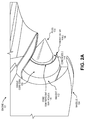
FIG. 3 illustrates a two dimensional (2D) cross-sectional view of theengine 102, according to aspects of the present disclosure. WhileFIG. 3 illustrates various components contained in theengine 102,FIG. 3 illustrates one example of an aircraft engine and additional components can be added and existing components can be removed. - As illustrated in
FIG. 3 , the annulus betweensingle core cowl 106 and the primaryouter wall 108 can form the corecompartment vent nozzle 116. The corecompartment vent nozzle 116 can be configured to vent the air flow from the core compartment through a large trailing edge between the fan flow and the core flow. In some aspects, the terminal end of thesingle core cowl 106 and the terminal end of the primaryouter wall 108 can be formed to have approximately planar alignment. In some aspects, the terminal end of thesingle core cowl 106 can be formed to be recessed from the terminal end of the primaryouter wall 108. -
FIG. 4 illustrates an example of a conventional core compartment vent arrangement of aconventional engine 200. As illustrated inFIG. 4 , the conventional core compartment vent arrangement of theconventional engine 200 includes aforward core cowl 202 and anaft core cowl 204. Theforward core cowl 202 and theaft core cowl 204 form a corecompartment vent nozzle 206. Additionally, the conventional core compartment vent of theconventional engine 200 includes abatwing ramp 208. Theconventional engine 200 also includes aheat shield 209 that forms aheat shield gap 210. Theconventional engine 200 also includes anaft fairing 212. In the conventional vent arrangement, the core nozzle outer wall may be subject to sonic fatigue issues and may need to be of greater thickness to compensate for the high thermal loads. Additionally, an aft fairing heat shield may need to be designed to allow for a gap between it and the core nozzle outer wall to accommodate relative motion between the engine and the aft fairing (not numbered) and heat shield (not numbered). Due to the longer nozzles, aft fairings and their heatshields may need to be longer. - In aspects, as discussed above in
FIGS. 2A ,2B , and3 , the core compartment air will exhaust in a trailing edge between thesingle core cowl 106 and the primaryouter wall 108.FIGS. 5A and 5B illustrate an example of the difference between the airflow inengine 102 shown inFIG. 5A and theconventional engine 200 shown inFIG. 5B .. As illustrated inFIG. 5B , the conventional engine can include theforward core cowl 202, theaft core cowl 204, and theplug 205. As illustrated inFIG. 5A (and discussed above with reference toFIG. 3 ), theengine 102 can include thesingle core cowl 106, the primaryouter wall 108, and theplug 110. In theengine 102, when compared to theconventional engine 200, theaft core cowl 204 can be removed, and the core compartment vent can be exhausted through a large trailing edge between the fan flow and the core flow. Additionally, the typical gap between the aft fairing heat shield and core nozzle can be eliminated due to the lack of relative motion between thesingle core cowl 106 and the aft fairing (not numbered). The batwing ramps 208 that transition fan air from theforward core cowl 202 to theaft core cowl 204 can be removed. - As such, the
engine 102 can allow for a shorter core nozzle, elimination of the aft core cowl, elimination of the core nozzle to heat shield gap and simplification of the core nozzle. For example, as illustrated inFIG. 5A , the removal of theaft core cowl 204 allows a difference in length of the primary outwall 108 as compared to theaft core cowl 204. That is, the primaryouter wall 108 of theengine 102 can be shorter than theaft core cowl 204 in theconventional engine 200. Inengine 102, thecore nozzle 114 may be exposed to reduced thermal stresses and may be shorter and lighter. Additionally, theplug 110 may be shorter and lighter. Due to the expected reduction in length, the nozzle would be lighter. Due to the reduced length, the aft fairing may also be shorter and lighter. Thus, theengine 102 may enable reduced weight and higher nozzle performance through reduced frictional surface losses. - Clause 1. A turbine engine nozzle, comprising:
- a primary outer wall extending from an engine core area to an annular wall terminus that surrounds an engine tail cone, to form a core nozzle; and
- a single engine core cowl extending from the engine core area to an annular cowl terminus to form a core compartment vent nozzle, wherein the core compartment vent nozzle exhausts air from a core compartment in a trailing edge between the single engine core cowl and the primary outer wall.
- Clause 2. The turbine engine nozzle of clause 1, wherein the single engine core cowl extends from the engine core area to annular cowl terminus in approximately planar alignment with the annular wall terminus.
- Clause 3. The turbine engine nozzle of clause 1 or 2, wherein the core compartment vent nozzle form an annulus between the single engine core cowl and the primary outer wall.
- Clause 4. The turbine engine nozzle of clause 1, wherein the single engine core cowl extends from the engine core area to annular cowl terminus that is recessed from the annular wall terminus.
- Clause 5. An aircraft engine, comprising
a ducted fan comprising a fan airflow exit for exhausting a fan air flow; and
a turbine engine core comprising:- a core nozzle for exhausting a core air flow from the turbine engine core, and
- a core compartment vent nozzle for exhausting core compartment vent air flow from a core compartment, wherein the core compartment vent nozzle exhausts core compartment vent air flow at a trailing edge between the fan air flow and the core air flow.
- Clause 6. The aircraft engine of clause 5, wherein the turbine engine core comprises:
- a primary outer wall extending from an engine core area to an annular wall terminus that surrounds an engine tail cone to form the core nozzle; and
- a single engine core cowl extending from the engine core area to an annular cowl terminus to form the core compartment vent nozzle.
- Clause 7. The aircraft engine of clause 6, wherein the single engine core cowl extends from the engine core area to annular cowl terminus in approximately planar alignment with the annular wall terminus.
- Clause 8. The aircraft engine of clause 6 or 7, wherein the core compartment vent nozzle form an annulus between the single engine core cowl and the primary outer wall.
- Clause 9. The aircraft engine of clause 6, wherein the single engine core cowl extends from the engine core area to annular cowl terminus that is recessed from the annular wall terminus.
- Clause 10. The aircraft engine of any of clauses 5 to 9, further comprising:
- an engine cover at least partially enclosing the ducted fan and the turbine engine core.
- Clause 11. An aircraft comprising:
- an aircraft body comprising a fuselage and at least one wing; and
- at least one aircraft engine, the at least one aircraft engine comprising:
- a ducted fan comprising a fan airflow exit for exhausting a fan air flow, and
- a turbine engine core comprising:
- a core nozzle for exhausting a core air flow from the turbine engine core, and
- a core compartment vent nozzle for exhausting core compartment vent air flow from a core compartment, wherein the core compartment vent nozzle exhausts core compartment vent air flow through a trailing edge between the fan air flow and the core air flow.
- Clause 12. The aircraft of clause 11, wherein the turbine engine core comprises:
- a primary outer wall extending from an engine core area to an annular wall terminus that surrounds an engine tail cone to form the core nozzle; and
- a single engine core cowl extending from the engine core area to an annular cowl terminus to form the core compartment vent nozzle.
- Clause 13. The aircraft of Clause 12, wherein the single engine core cowl extends from the engine core area to annular cowl terminus in approximately planar alignment with the annular wall terminus.
- Clause 14. The aircraft of clause 12, wherein the core compartment vent nozzle form an annulus between the single engine core cowl and the primary outer wall.
- Clause 15. The aircraft of clause 12 or 14, wherein the single engine core cowl extends from the engine core area to annular cowl terminus that is recessed from the annular wall terminus.
- Clause 16. The aircraft of any of clauses 11 to 15, further comprising:
- an engine cover at least partially enclosing the ducted fan and the turbine engine core.
- Clause 17. The aircraft of any- of clauses 11 to 16, wherein the at least one aircraft engine is coupled to the at least one wing.
- While the teachings have been described with reference to examples of the implementations thereof, those skilled in the art will be able to make various modifications to the described implementations without departing from the true spirit and scope. The terms and descriptions used herein are set forth by way of illustration only and are not meant as limitations. In particular, although the processes have been described by examples, the stages of the processes can be performed in a different order than illustrated or simultaneously. Furthermore, to the extent that the terms "including", "includes", "having", "has", "with", or variants thereof are used in the detailed description, such terms are intended to be inclusive in a manner similar to the term "comprising." As used herein, the terms "one or more of" and "at least one of" with respect to a listing of items such as, for example, A and B, means A alone, B alone, or A and B. Further, unless specified otherwise, the term "set" should be interpreted as "one or more." Also, the term "couple" or "couples" is intended to mean either an indirect or direct connection. Thus, if a first device couples to a second device, that connection can be through a direct connection, or through an indirect connection via other devices, components, and connections.
Claims (15)
- A turbine engine nozzle, comprising:a primary outer wall (108) extending from an engine core area to an annular wall terminus that surrounds an engine tail cone, to form a core nozzle (114); anda single engine core cowl (106) extending from the engine core area to an annular cowl terminus to form a core compartment vent nozzle (116), wherein the core compartment vent nozzle exhausts air from a core compartment in a trailing edge between the single engine core cowl (106) and the primary outer wall (108).
- The turbine engine nozzle of claim 1, wherein the single engine core cowl (106) extends from the engine core area to annular cowl terminus in approximately planar alignment with the annular wall terminus.
- The turbine engine nozzle of claim 1 or 2, wherein the core compartment vent nozzle (116) form an annulus between the single engine core cowl and the primary outer wall.
- The turbine engine nozzle of claim 1, wherein the single engine core cowl (106) extends from the engine core area to annular cowl terminus that is recessed from the annular wall terminus.
- An aircraft engine (102), comprising
a ducted fan comprising a fan airflow exit (112) for exhausting a fan air flow; and
a turbine engine core comprising:a core nozzle (114) for exhausting a core air flow from the turbine engine core, anda core compartment vent nozzle (116) for exhausting core compartment vent air flow from a core compartment, wherein the core compartment vent nozzle (116) exhausts core compartment vent air flow at a trailing edge between the fan air flow and the core air flow. - The aircraft engine (102) of claim 5, wherein the turbine engine core comprises:a primary outer wall (108) extending from an engine core area to an annular wall terminus that surrounds an engine tail cone to form the core nozzle (114); anda single engine core cowl (106) extending from the engine core area to an annular cowl terminus to form the core compartment vent nozzle (116).
- The aircraft engine of claim 6, wherein the single engine core cowl (106) extends from the engine core area to annular cowl terminus in approximately planar alignment with the annular wall terminus.
- The aircraft engine of claim 6 or 7, wherein the core compartment vent nozzle (116) form an annulus between the single engine core cowl and the primary outer wall.
- The aircraft engine of claim 6, wherein the single engine core cowl (106) extends from the engine core area to annular cowl terminus that is recessed from the annular wall terminus.
- The aircraft engine (102) of any of claims 5 to 9, further comprising:an engine cover at least partially enclosing the ducted fan and the turbine engine core.
- An aircraft (100) comprising:an aircraft body comprising a fuselage and at least one wing; andat least one aircraft engine (102), the at least one aircraft engine comprising:a ducted fan comprising a fan airflow exit (112) for exhausting a fan air flow, anda turbine engine core comprising:a core nozzle (114) for exhausting a core air flow from the turbine engine core, anda core compartment vent nozzle (116) for exhausting core compartment vent air flow from a core compartment, wherein the core compartment vent nozzle (116) exhausts core compartment vent air flow through a trailing edge between the fan air flow and the core air flow.
- The aircraft (100) of claim 11, wherein the turbine engine core comprises:a primary outer wall (108) extending from an engine core area to an annular wall terminus that surrounds an engine tail cone to form the core nozzle (114); anda single engine core cowl (106) extending from the engine core area to an annular cowl terminus to form the core compartment vent nozzle (116).
- The aircraft (100) of claim 12, wherein the single engine core cowl (106) extends from the engine core area to annular cowl terminus in approximately planar alignment with the annular wall terminus.
- The aircraft of claim 12, wherein the core compartment vent nozzle (116) form an annulus between the single engine core cowl and the primary outer wall; and
wherein the single engine core cowl (106) extends from the engine core area to annular cowl terminus that is recessed from the annular wall terminus. - The aircraft (100) of any of claims 11 to 14, further comprising:an engine cover at least partially enclosing the ducted fan and the turbine engine core.
Applications Claiming Priority (1)
| Application Number | Priority Date | Filing Date | Title |
|---|---|---|---|
| US14/870,401 US10040560B2 (en) | 2015-09-30 | 2015-09-30 | Trailing edge core compartment vent for an aircraft engine |
Publications (2)
| Publication Number | Publication Date |
|---|---|
| EP3150807A1 true EP3150807A1 (en) | 2017-04-05 |
| EP3150807B1 EP3150807B1 (en) | 2021-06-16 |
Family
ID=56321871
Family Applications (1)
| Application Number | Title | Priority Date | Filing Date |
|---|---|---|---|
| EP16177843.6A Active EP3150807B1 (en) | 2015-09-30 | 2016-07-04 | Trailing edge core compartment vent for an aircraft engine |
Country Status (7)
| Country | Link |
|---|---|
| US (1) | US10040560B2 (en) |
| EP (1) | EP3150807B1 (en) |
| JP (1) | JP7329900B2 (en) |
| KR (1) | KR102572482B1 (en) |
| CN (1) | CN106555704B (en) |
| BR (1) | BR102016018513B1 (en) |
| CA (1) | CA2935049C (en) |
Families Citing this family (3)
| Publication number | Priority date | Publication date | Assignee | Title |
|---|---|---|---|---|
| US10989114B2 (en) | 2018-03-07 | 2021-04-27 | The Boeing Company | Systems and methods for cooling bleed air from an aircraft engine |
| FR3082551B1 (en) * | 2018-06-13 | 2021-01-08 | Airbus Operations Sas | PROPULSION SYSTEM OF AN AIRCRAFT CONTAINING A FIXED INTERIOR STRUCTURE PRESENTING AN EXHAUST SLOT |
| US11746726B2 (en) | 2020-05-05 | 2023-09-05 | Rohr, Inc. | Aircraft propulsion system nozzle with internal flow passage |
Citations (3)
| Publication number | Priority date | Publication date | Assignee | Title |
|---|---|---|---|---|
| US20080141656A1 (en) * | 2006-08-01 | 2008-06-19 | Snecma | Bypass turbomachine with artificial variation of its throat section |
| US20080202847A1 (en) * | 2005-09-12 | 2008-08-28 | Alain Porte | Method For Attenuating the Noise of a Turbofan |
| US20090007567A1 (en) * | 2006-01-19 | 2009-01-08 | Airbus France | Dual Flow Turbine Engine Equipped with a Precooler |
Family Cites Families (28)
| Publication number | Priority date | Publication date | Assignee | Title |
|---|---|---|---|---|
| US3527317A (en) * | 1969-04-18 | 1970-09-08 | Gen Electric | Sound control of turbofan engines |
| US3780827A (en) * | 1972-12-19 | 1973-12-25 | Nasa | Gas turbine exhaust nozzle |
| CA1020365A (en) * | 1974-02-25 | 1977-11-08 | James E. Johnson | Modulating bypass variable cycle turbofan engine |
| US3964569A (en) * | 1974-09-06 | 1976-06-22 | General Electric Company | Gas turbine engine noise shield |
| US3964568A (en) * | 1974-09-06 | 1976-06-22 | General Electric Company | Gas turbine engine noise shield |
| US3946830A (en) * | 1974-09-06 | 1976-03-30 | General Electric Company | Inlet noise deflector |
| US5056307A (en) * | 1990-05-25 | 1991-10-15 | The United States Of America As Represented By The Secretary Of The Air Force | Exhaust nozzle cooling utilizing total engine flow |
| GB2312251B (en) * | 1996-04-18 | 1999-10-27 | Rolls Royce Plc | Ducted fan gas turbine engine mounting |
| US6227800B1 (en) * | 1998-11-24 | 2001-05-08 | General Electric Company | Bay cooled turbine casing |
| WO2003099654A2 (en) * | 2002-05-21 | 2003-12-04 | The Nordam Group, Inc. | Bifurcated turbofan exhaust nozzle |
| ATE523682T1 (en) * | 2005-09-27 | 2011-09-15 | Volvo Aero Corp | ARRANGEMENT FOR DRIVING AN AIRCRAFT, AIRCRAFT AND EXHAUST NOZZLE FOR A JET ENGINE |
| FR2892152B1 (en) * | 2005-10-19 | 2007-11-23 | Airbus France Sas | TURBOMOTEUR WITH ATTENUATED JET NOISE |
| JP2007285245A (en) * | 2006-04-19 | 2007-11-01 | Japan Aerospace Exploration Agency | Noise suppression device |
| GB2437295B (en) * | 2006-04-20 | 2008-06-25 | Rolls Royce Plc | Aeroengine ventilation system |
| US7726116B2 (en) * | 2006-11-14 | 2010-06-01 | General Electric Company | Turbofan engine nozzle assembly and method of operating same |
| US20080114656A1 (en) * | 2006-11-15 | 2008-05-15 | Airport Marketing Income, L.L.C. | Airport radio |
| US7805924B2 (en) * | 2006-11-30 | 2010-10-05 | United Technologies Corporation | Thermally decoupled mixer |
| FR2916808B1 (en) * | 2007-05-31 | 2013-02-22 | Airbus France | DUAL FLOW TURBOMOTEUR HAVING IMPROVED HOT FLUX TUBE. |
| FR2916737B1 (en) * | 2007-06-01 | 2010-05-28 | Airbus France | AIRCRAFT ENGINE ASSEMBLY WITH SLIDING CARGO. |
| FR2934566B1 (en) * | 2008-08-04 | 2011-03-11 | Aircelle Sa | METHOD FOR MANUFACTURING A DEFROSTING ASSEMBLY ON A PANEL OF A NACELLE |
| FR2942457B1 (en) * | 2009-02-24 | 2011-04-22 | Snecma | TURBOREACTOR NACELLE WITH REMOVABLE AIR INTAKE STRUCTURE |
| US8181441B2 (en) * | 2009-02-27 | 2012-05-22 | United Technologies Corporation | Controlled fan stream flow bypass |
| US9388740B2 (en) * | 2012-02-15 | 2016-07-12 | The Boeing Company | Thermoelectric generator in turbine engine nozzles |
| US9347397B2 (en) * | 2012-08-02 | 2016-05-24 | United Technologies Corporation | Reflex annular vent nozzle |
| FR2997681B1 (en) * | 2012-11-08 | 2015-05-15 | Snecma | PLANE PROPELLED BY A TURBOREACTOR WITH CONTRAROTATIVE BLOWERS |
| US10197008B2 (en) * | 2013-02-19 | 2019-02-05 | United Technologies Corporation | Gas turbine engine including a third flowpath exhaust nozzle |
| US9863366B2 (en) * | 2013-03-13 | 2018-01-09 | Rolls-Royce North American Technologies Inc. | Exhaust nozzle apparatus and method for multi stream aircraft engine |
| FR3028289B1 (en) * | 2014-11-06 | 2019-12-27 | Airbus Operations (S.A.S.) | AIRCRAFT TURBOMACHINE COMPRISING AN AIR INTAKE BOX WITH VARIABLE AERODYNAMIC PROFILE |
-
2015
- 2015-09-30 US US14/870,401 patent/US10040560B2/en active Active
-
2016
- 2016-06-30 CA CA2935049A patent/CA2935049C/en active Active
- 2016-07-04 EP EP16177843.6A patent/EP3150807B1/en active Active
- 2016-07-18 KR KR1020160090500A patent/KR102572482B1/en active Active
- 2016-08-12 BR BR102016018513-0A patent/BR102016018513B1/en active IP Right Grant
- 2016-09-09 CN CN201610819112.9A patent/CN106555704B/en active Active
- 2016-09-29 JP JP2016191366A patent/JP7329900B2/en active Active
Patent Citations (3)
| Publication number | Priority date | Publication date | Assignee | Title |
|---|---|---|---|---|
| US20080202847A1 (en) * | 2005-09-12 | 2008-08-28 | Alain Porte | Method For Attenuating the Noise of a Turbofan |
| US20090007567A1 (en) * | 2006-01-19 | 2009-01-08 | Airbus France | Dual Flow Turbine Engine Equipped with a Precooler |
| US20080141656A1 (en) * | 2006-08-01 | 2008-06-19 | Snecma | Bypass turbomachine with artificial variation of its throat section |
Also Published As
| Publication number | Publication date |
|---|---|
| JP2017096253A (en) | 2017-06-01 |
| US20170088275A1 (en) | 2017-03-30 |
| CN106555704A (en) | 2017-04-05 |
| KR102572482B1 (en) | 2023-08-30 |
| CN106555704B (en) | 2020-10-30 |
| CA2935049A1 (en) | 2017-03-30 |
| JP7329900B2 (en) | 2023-08-21 |
| US10040560B2 (en) | 2018-08-07 |
| BR102016018513A2 (en) | 2018-04-03 |
| BR102016018513B1 (en) | 2023-01-10 |
| KR20170038642A (en) | 2017-04-07 |
| CA2935049C (en) | 2020-06-16 |
| EP3150807B1 (en) | 2021-06-16 |
Similar Documents
| Publication | Publication Date | Title |
|---|---|---|
| CN107521705B (en) | Assembly for an aircraft comprising an engine with boundary layer suction propulsion | |
| US10752371B2 (en) | Translating nacelle wall for an aircraft tail mounted fan section | |
| EP3060778B1 (en) | Anti-icing system for an aircraft | |
| EP2863038B1 (en) | Thrust reverser fan ramp with blocker door pocket | |
| US10920713B2 (en) | Compression cowl for jet engine exhaust | |
| WO2015012920A3 (en) | Secondary nozzle for jet engine | |
| JP6806474B2 (en) | Intake flow limiter | |
| US10167086B2 (en) | Anti-icing system for an aircraft | |
| US20160258358A1 (en) | High turning angle ejector cooled turbine engine exhaust duct | |
| CA2935049C (en) | Trailing edge core compartment vent for an aircraft engine | |
| US20150107222A1 (en) | Thrust reverser fan ramp partially formed on aft end of fan case | |
| EP3778402B1 (en) | Pusher turboprop powerplant installation | |
| US20170009704A1 (en) | Thrust reverser staggered translating sleeve | |
| US10533520B2 (en) | Radially connected cascade grids | |
| US12359587B2 (en) | Gas turbine engine power cable cooling | |
| US20140130889A1 (en) | Air inlet structure for turbojet engine nacelle | |
| US10696415B2 (en) | Propulsion unit for an aircraft, with reduced aerodynamic drag | |
| US9822733B2 (en) | Aerodynamic feature for aft edge portions of thrust reverser lower bifurcation wall | |
| EP4571074A1 (en) | Nacelle for turbo-propeller engines | |
| JP2001153600A (en) | Fuselage cooling method and fuselage cooling structure |
Legal Events
| Date | Code | Title | Description |
|---|---|---|---|
| PUAI | Public reference made under article 153(3) epc to a published international application that has entered the european phase |
Free format text: ORIGINAL CODE: 0009012 |
|
| STAA | Information on the status of an ep patent application or granted ep patent |
Free format text: STATUS: REQUEST FOR EXAMINATION WAS MADE |
|
| 17P | Request for examination filed |
Effective date: 20160704 |
|
| AK | Designated contracting states |
Kind code of ref document: A1 Designated state(s): AL AT BE BG CH CY CZ DE DK EE ES FI FR GB GR HR HU IE IS IT LI LT LU LV MC MK MT NL NO PL PT RO RS SE SI SK SM TR |
|
| AX | Request for extension of the european patent |
Extension state: BA ME |
|
| RBV | Designated contracting states (corrected) |
Designated state(s): AL AT BE BG CH CY CZ DE DK EE ES FI FR GB GR HR HU IE IS IT LI LT LU LV MC MK MT NL NO PL PT RO RS SE SI SK SM TR |
|
| STAA | Information on the status of an ep patent application or granted ep patent |
Free format text: STATUS: EXAMINATION IS IN PROGRESS |
|
| 17Q | First examination report despatched |
Effective date: 20190409 |
|
| GRAP | Despatch of communication of intention to grant a patent |
Free format text: ORIGINAL CODE: EPIDOSNIGR1 |
|
| STAA | Information on the status of an ep patent application or granted ep patent |
Free format text: STATUS: GRANT OF PATENT IS INTENDED |
|
| INTG | Intention to grant announced |
Effective date: 20210129 |
|
| GRAS | Grant fee paid |
Free format text: ORIGINAL CODE: EPIDOSNIGR3 |
|
| GRAA | (expected) grant |
Free format text: ORIGINAL CODE: 0009210 |
|
| STAA | Information on the status of an ep patent application or granted ep patent |
Free format text: STATUS: THE PATENT HAS BEEN GRANTED |
|
| AK | Designated contracting states |
Kind code of ref document: B1 Designated state(s): AL AT BE BG CH CY CZ DE DK EE ES FI FR GB GR HR HU IE IS IT LI LT LU LV MC MK MT NL NO PL PT RO RS SE SI SK SM TR |
|
| REG | Reference to a national code |
Ref country code: GB Ref legal event code: FG4D |
|
| REG | Reference to a national code |
Ref country code: CH Ref legal event code: EP |
|
| REG | Reference to a national code |
Ref country code: DE Ref legal event code: R096 Ref document number: 602016059296 Country of ref document: DE |
|
| REG | Reference to a national code |
Ref country code: AT Ref legal event code: REF Ref document number: 1402490 Country of ref document: AT Kind code of ref document: T Effective date: 20210715 |
|
| REG | Reference to a national code |
Ref country code: IE Ref legal event code: FG4D |
|
| REG | Reference to a national code |
Ref country code: LT Ref legal event code: MG9D |
|
| PG25 | Lapsed in a contracting state [announced via postgrant information from national office to epo] |
Ref country code: HR Free format text: LAPSE BECAUSE OF FAILURE TO SUBMIT A TRANSLATION OF THE DESCRIPTION OR TO PAY THE FEE WITHIN THE PRESCRIBED TIME-LIMIT Effective date: 20210616 Ref country code: BG Free format text: LAPSE BECAUSE OF FAILURE TO SUBMIT A TRANSLATION OF THE DESCRIPTION OR TO PAY THE FEE WITHIN THE PRESCRIBED TIME-LIMIT Effective date: 20210916 Ref country code: LT Free format text: LAPSE BECAUSE OF FAILURE TO SUBMIT A TRANSLATION OF THE DESCRIPTION OR TO PAY THE FEE WITHIN THE PRESCRIBED TIME-LIMIT Effective date: 20210616 Ref country code: FI Free format text: LAPSE BECAUSE OF FAILURE TO SUBMIT A TRANSLATION OF THE DESCRIPTION OR TO PAY THE FEE WITHIN THE PRESCRIBED TIME-LIMIT Effective date: 20210616 |
|
| REG | Reference to a national code |
Ref country code: AT Ref legal event code: MK05 Ref document number: 1402490 Country of ref document: AT Kind code of ref document: T Effective date: 20210616 |
|
| REG | Reference to a national code |
Ref country code: NL Ref legal event code: MP Effective date: 20210616 |
|
| PG25 | Lapsed in a contracting state [announced via postgrant information from national office to epo] |
Ref country code: LV Free format text: LAPSE BECAUSE OF FAILURE TO SUBMIT A TRANSLATION OF THE DESCRIPTION OR TO PAY THE FEE WITHIN THE PRESCRIBED TIME-LIMIT Effective date: 20210616 Ref country code: GR Free format text: LAPSE BECAUSE OF FAILURE TO SUBMIT A TRANSLATION OF THE DESCRIPTION OR TO PAY THE FEE WITHIN THE PRESCRIBED TIME-LIMIT Effective date: 20210917 Ref country code: NO Free format text: LAPSE BECAUSE OF FAILURE TO SUBMIT A TRANSLATION OF THE DESCRIPTION OR TO PAY THE FEE WITHIN THE PRESCRIBED TIME-LIMIT Effective date: 20210916 Ref country code: RS Free format text: LAPSE BECAUSE OF FAILURE TO SUBMIT A TRANSLATION OF THE DESCRIPTION OR TO PAY THE FEE WITHIN THE PRESCRIBED TIME-LIMIT Effective date: 20210616 Ref country code: SE Free format text: LAPSE BECAUSE OF FAILURE TO SUBMIT A TRANSLATION OF THE DESCRIPTION OR TO PAY THE FEE WITHIN THE PRESCRIBED TIME-LIMIT Effective date: 20210616 |
|
| PG25 | Lapsed in a contracting state [announced via postgrant information from national office to epo] |
Ref country code: SM Free format text: LAPSE BECAUSE OF FAILURE TO SUBMIT A TRANSLATION OF THE DESCRIPTION OR TO PAY THE FEE WITHIN THE PRESCRIBED TIME-LIMIT Effective date: 20210616 Ref country code: SK Free format text: LAPSE BECAUSE OF FAILURE TO SUBMIT A TRANSLATION OF THE DESCRIPTION OR TO PAY THE FEE WITHIN THE PRESCRIBED TIME-LIMIT Effective date: 20210616 Ref country code: EE Free format text: LAPSE BECAUSE OF FAILURE TO SUBMIT A TRANSLATION OF THE DESCRIPTION OR TO PAY THE FEE WITHIN THE PRESCRIBED TIME-LIMIT Effective date: 20210616 Ref country code: CZ Free format text: LAPSE BECAUSE OF FAILURE TO SUBMIT A TRANSLATION OF THE DESCRIPTION OR TO PAY THE FEE WITHIN THE PRESCRIBED TIME-LIMIT Effective date: 20210616 Ref country code: AT Free format text: LAPSE BECAUSE OF FAILURE TO SUBMIT A TRANSLATION OF THE DESCRIPTION OR TO PAY THE FEE WITHIN THE PRESCRIBED TIME-LIMIT Effective date: 20210616 Ref country code: RO Free format text: LAPSE BECAUSE OF FAILURE TO SUBMIT A TRANSLATION OF THE DESCRIPTION OR TO PAY THE FEE WITHIN THE PRESCRIBED TIME-LIMIT Effective date: 20210616 Ref country code: NL Free format text: LAPSE BECAUSE OF FAILURE TO SUBMIT A TRANSLATION OF THE DESCRIPTION OR TO PAY THE FEE WITHIN THE PRESCRIBED TIME-LIMIT Effective date: 20210616 Ref country code: PT Free format text: LAPSE BECAUSE OF FAILURE TO SUBMIT A TRANSLATION OF THE DESCRIPTION OR TO PAY THE FEE WITHIN THE PRESCRIBED TIME-LIMIT Effective date: 20211018 Ref country code: ES Free format text: LAPSE BECAUSE OF FAILURE TO SUBMIT A TRANSLATION OF THE DESCRIPTION OR TO PAY THE FEE WITHIN THE PRESCRIBED TIME-LIMIT Effective date: 20210616 |
|
| PG25 | Lapsed in a contracting state [announced via postgrant information from national office to epo] |
Ref country code: PL Free format text: LAPSE BECAUSE OF FAILURE TO SUBMIT A TRANSLATION OF THE DESCRIPTION OR TO PAY THE FEE WITHIN THE PRESCRIBED TIME-LIMIT Effective date: 20210616 |
|
| REG | Reference to a national code |
Ref country code: CH Ref legal event code: PL |
|
| REG | Reference to a national code |
Ref country code: DE Ref legal event code: R097 Ref document number: 602016059296 Country of ref document: DE |
|
| PG25 | Lapsed in a contracting state [announced via postgrant information from national office to epo] |
Ref country code: MC Free format text: LAPSE BECAUSE OF FAILURE TO SUBMIT A TRANSLATION OF THE DESCRIPTION OR TO PAY THE FEE WITHIN THE PRESCRIBED TIME-LIMIT Effective date: 20210616 |
|
| REG | Reference to a national code |
Ref country code: BE Ref legal event code: MM Effective date: 20210731 |
|
| PLBE | No opposition filed within time limit |
Free format text: ORIGINAL CODE: 0009261 |
|
| STAA | Information on the status of an ep patent application or granted ep patent |
Free format text: STATUS: NO OPPOSITION FILED WITHIN TIME LIMIT |
|
| PG25 | Lapsed in a contracting state [announced via postgrant information from national office to epo] |
Ref country code: LI Free format text: LAPSE BECAUSE OF NON-PAYMENT OF DUE FEES Effective date: 20210731 Ref country code: DK Free format text: LAPSE BECAUSE OF FAILURE TO SUBMIT A TRANSLATION OF THE DESCRIPTION OR TO PAY THE FEE WITHIN THE PRESCRIBED TIME-LIMIT Effective date: 20210616 Ref country code: CH Free format text: LAPSE BECAUSE OF NON-PAYMENT OF DUE FEES Effective date: 20210731 |
|
| 26N | No opposition filed |
Effective date: 20220317 |
|
| PG25 | Lapsed in a contracting state [announced via postgrant information from national office to epo] |
Ref country code: LU Free format text: LAPSE BECAUSE OF NON-PAYMENT OF DUE FEES Effective date: 20210704 Ref country code: AL Free format text: LAPSE BECAUSE OF FAILURE TO SUBMIT A TRANSLATION OF THE DESCRIPTION OR TO PAY THE FEE WITHIN THE PRESCRIBED TIME-LIMIT Effective date: 20210616 |
|
| PG25 | Lapsed in a contracting state [announced via postgrant information from national office to epo] |
Ref country code: IT Free format text: LAPSE BECAUSE OF FAILURE TO SUBMIT A TRANSLATION OF THE DESCRIPTION OR TO PAY THE FEE WITHIN THE PRESCRIBED TIME-LIMIT Effective date: 20210616 Ref country code: IE Free format text: LAPSE BECAUSE OF NON-PAYMENT OF DUE FEES Effective date: 20210704 Ref country code: BE Free format text: LAPSE BECAUSE OF NON-PAYMENT OF DUE FEES Effective date: 20210731 |
|
| PG25 | Lapsed in a contracting state [announced via postgrant information from national office to epo] |
Ref country code: HU Free format text: LAPSE BECAUSE OF FAILURE TO SUBMIT A TRANSLATION OF THE DESCRIPTION OR TO PAY THE FEE WITHIN THE PRESCRIBED TIME-LIMIT; INVALID AB INITIO Effective date: 20160704 |
|
| P01 | Opt-out of the competence of the unified patent court (upc) registered |
Effective date: 20230516 |
|
| PG25 | Lapsed in a contracting state [announced via postgrant information from national office to epo] |
Ref country code: CY Free format text: LAPSE BECAUSE OF FAILURE TO SUBMIT A TRANSLATION OF THE DESCRIPTION OR TO PAY THE FEE WITHIN THE PRESCRIBED TIME-LIMIT Effective date: 20210616 |
|
| PG25 | Lapsed in a contracting state [announced via postgrant information from national office to epo] |
Ref country code: MK Free format text: LAPSE BECAUSE OF FAILURE TO SUBMIT A TRANSLATION OF THE DESCRIPTION OR TO PAY THE FEE WITHIN THE PRESCRIBED TIME-LIMIT Effective date: 20210616 |
|
| PG25 | Lapsed in a contracting state [announced via postgrant information from national office to epo] |
Ref country code: MT Free format text: LAPSE BECAUSE OF FAILURE TO SUBMIT A TRANSLATION OF THE DESCRIPTION OR TO PAY THE FEE WITHIN THE PRESCRIBED TIME-LIMIT Effective date: 20210616 |
|
| PGFP | Annual fee paid to national office [announced via postgrant information from national office to epo] |
Ref country code: DE Payment date: 20250729 Year of fee payment: 10 |
|
| PGFP | Annual fee paid to national office [announced via postgrant information from national office to epo] |
Ref country code: GB Payment date: 20250728 Year of fee payment: 10 |
|
| PGFP | Annual fee paid to national office [announced via postgrant information from national office to epo] |
Ref country code: FR Payment date: 20250725 Year of fee payment: 10 |
|
| PG25 | Lapsed in a contracting state [announced via postgrant information from national office to epo] |
Ref country code: TR Free format text: LAPSE BECAUSE OF FAILURE TO SUBMIT A TRANSLATION OF THE DESCRIPTION OR TO PAY THE FEE WITHIN THE PRESCRIBED TIME-LIMIT Effective date: 20210616 |