EP3150512A1 - Capsule, system and method for preparing a predetermined quantity of beverage suitable for consumption - Google Patents
Capsule, system and method for preparing a predetermined quantity of beverage suitable for consumption Download PDFInfo
- Publication number
- EP3150512A1 EP3150512A1 EP16196383.0A EP16196383A EP3150512A1 EP 3150512 A1 EP3150512 A1 EP 3150512A1 EP 16196383 A EP16196383 A EP 16196383A EP 3150512 A1 EP3150512 A1 EP 3150512A1
- Authority
- EP
- European Patent Office
- Prior art keywords
- capsule
- capsule according
- ridges
- projection
- ridge
- Prior art date
- Legal status (The legal status is an assumption and is not a legal conclusion. Google has not performed a legal analysis and makes no representation as to the accuracy of the status listed.)
- Granted
Links
- 239000002775 capsule Substances 0.000 title claims abstract description 283
- 235000013361 beverage Nutrition 0.000 title claims abstract description 39
- 238000000034 method Methods 0.000 title claims description 6
- 238000007789 sealing Methods 0.000 claims abstract description 71
- 239000000463 material Substances 0.000 claims description 46
- 239000012530 fluid Substances 0.000 claims description 21
- XLYOFNOQVPJJNP-UHFFFAOYSA-N water Substances O XLYOFNOQVPJJNP-UHFFFAOYSA-N 0.000 claims description 12
- 239000004033 plastic Substances 0.000 claims description 9
- 229920003023 plastic Polymers 0.000 claims description 9
- 239000007788 liquid Substances 0.000 claims description 5
- 235000013353 coffee beverage Nutrition 0.000 description 11
- 230000006835 compression Effects 0.000 description 11
- 238000007906 compression Methods 0.000 description 11
- 230000000994 depressogenic effect Effects 0.000 description 4
- 238000004519 manufacturing process Methods 0.000 description 4
- 210000003027 ear inner Anatomy 0.000 description 3
- 239000004615 ingredient Substances 0.000 description 3
- 230000001788 irregular Effects 0.000 description 3
- 230000000116 mitigating effect Effects 0.000 description 3
- 239000004411 aluminium Substances 0.000 description 2
- 229910052782 aluminium Inorganic materials 0.000 description 2
- XAGFODPZIPBFFR-UHFFFAOYSA-N aluminium Chemical compound [Al] XAGFODPZIPBFFR-UHFFFAOYSA-N 0.000 description 2
- 230000015556 catabolic process Effects 0.000 description 2
- 230000000295 complement effect Effects 0.000 description 2
- 238000006731 degradation reaction Methods 0.000 description 2
- 210000004209 hair Anatomy 0.000 description 2
- 238000002347 injection Methods 0.000 description 2
- 239000007924 injection Substances 0.000 description 2
- 238000001746 injection moulding Methods 0.000 description 2
- 238000003780 insertion Methods 0.000 description 2
- 230000037431 insertion Effects 0.000 description 2
- 238000012986 modification Methods 0.000 description 2
- 230000004048 modification Effects 0.000 description 2
- 239000000126 substance Substances 0.000 description 2
- 239000004743 Polypropylene Substances 0.000 description 1
- 238000010521 absorption reaction Methods 0.000 description 1
- 239000000853 adhesive Substances 0.000 description 1
- 230000001070 adhesive effect Effects 0.000 description 1
- 230000004888 barrier function Effects 0.000 description 1
- 230000001427 coherent effect Effects 0.000 description 1
- 230000007547 defect Effects 0.000 description 1
- 230000000694 effects Effects 0.000 description 1
- 239000013536 elastomeric material Substances 0.000 description 1
- 239000003000 extruded plastic Substances 0.000 description 1
- 239000011888 foil Substances 0.000 description 1
- 238000007373 indentation Methods 0.000 description 1
- 230000003993 interaction Effects 0.000 description 1
- 229910052751 metal Inorganic materials 0.000 description 1
- 239000002184 metal Substances 0.000 description 1
- 230000000813 microbial effect Effects 0.000 description 1
- 239000000203 mixture Substances 0.000 description 1
- 238000000465 moulding Methods 0.000 description 1
- -1 polypropylene Polymers 0.000 description 1
- 229920001155 polypropylene Polymers 0.000 description 1
- 239000011148 porous material Substances 0.000 description 1
- 238000003825 pressing Methods 0.000 description 1
- 239000007779 soft material Substances 0.000 description 1
Images


Classifications
-
- B—PERFORMING OPERATIONS; TRANSPORTING
- B65—CONVEYING; PACKING; STORING; HANDLING THIN OR FILAMENTARY MATERIAL
- B65D—CONTAINERS FOR STORAGE OR TRANSPORT OF ARTICLES OR MATERIALS, e.g. BAGS, BARRELS, BOTTLES, BOXES, CANS, CARTONS, CRATES, DRUMS, JARS, TANKS, HOPPERS, FORWARDING CONTAINERS; ACCESSORIES, CLOSURES, OR FITTINGS THEREFOR; PACKAGING ELEMENTS; PACKAGES
- B65D85/00—Containers, packaging elements or packages, specially adapted for particular articles or materials
- B65D85/70—Containers, packaging elements or packages, specially adapted for particular articles or materials for materials not otherwise provided for
- B65D85/804—Disposable containers or packages with contents which are mixed, infused or dissolved in situ, i.e. without having been previously removed from the package
- B65D85/8043—Packages adapted to allow liquid to pass through the contents
- B65D85/8064—Sealing means for the interface with the processing machine
-
- A—HUMAN NECESSITIES
- A23—FOODS OR FOODSTUFFS; TREATMENT THEREOF, NOT COVERED BY OTHER CLASSES
- A23F—COFFEE; TEA; THEIR SUBSTITUTES; MANUFACTURE, PREPARATION, OR INFUSION THEREOF
- A23F5/00—Coffee; Coffee substitutes; Preparations thereof
- A23F5/24—Extraction of coffee; Coffee extracts; Making instant coffee
- A23F5/26—Extraction of water-soluble constituents
- A23F5/262—Extraction of water-soluble constituents the extraction liquid flows through a stationary bed of solid substances, e.g. in percolation columns
-
- A—HUMAN NECESSITIES
- A47—FURNITURE; DOMESTIC ARTICLES OR APPLIANCES; COFFEE MILLS; SPICE MILLS; SUCTION CLEANERS IN GENERAL
- A47J—KITCHEN EQUIPMENT; COFFEE MILLS; SPICE MILLS; APPARATUS FOR MAKING BEVERAGES
- A47J31/00—Apparatus for making beverages
- A47J31/06—Filters or strainers for coffee or tea makers ; Holders therefor
-
- A—HUMAN NECESSITIES
- A47—FURNITURE; DOMESTIC ARTICLES OR APPLIANCES; COFFEE MILLS; SPICE MILLS; SUCTION CLEANERS IN GENERAL
- A47J—KITCHEN EQUIPMENT; COFFEE MILLS; SPICE MILLS; APPARATUS FOR MAKING BEVERAGES
- A47J31/00—Apparatus for making beverages
- A47J31/24—Coffee-making apparatus in which hot water is passed through the filter under pressure, i.e. in which the coffee grounds are extracted under pressure
- A47J31/34—Coffee-making apparatus in which hot water is passed through the filter under pressure, i.e. in which the coffee grounds are extracted under pressure with hot water under liquid pressure
- A47J31/36—Coffee-making apparatus in which hot water is passed through the filter under pressure, i.e. in which the coffee grounds are extracted under pressure with hot water under liquid pressure with mechanical pressure-producing means
- A47J31/3666—Coffee-making apparatus in which hot water is passed through the filter under pressure, i.e. in which the coffee grounds are extracted under pressure with hot water under liquid pressure with mechanical pressure-producing means whereby the loading of the brewing chamber with the brewing material is performed by the user
- A47J31/3676—Cartridges being employed
- A47J31/368—Permeable cartridges being employed
-
- A—HUMAN NECESSITIES
- A47—FURNITURE; DOMESTIC ARTICLES OR APPLIANCES; COFFEE MILLS; SPICE MILLS; SUCTION CLEANERS IN GENERAL
- A47J—KITCHEN EQUIPMENT; COFFEE MILLS; SPICE MILLS; APPARATUS FOR MAKING BEVERAGES
- A47J31/00—Apparatus for making beverages
- A47J31/24—Coffee-making apparatus in which hot water is passed through the filter under pressure, i.e. in which the coffee grounds are extracted under pressure
- A47J31/34—Coffee-making apparatus in which hot water is passed through the filter under pressure, i.e. in which the coffee grounds are extracted under pressure with hot water under liquid pressure
- A47J31/36—Coffee-making apparatus in which hot water is passed through the filter under pressure, i.e. in which the coffee grounds are extracted under pressure with hot water under liquid pressure with mechanical pressure-producing means
- A47J31/3666—Coffee-making apparatus in which hot water is passed through the filter under pressure, i.e. in which the coffee grounds are extracted under pressure with hot water under liquid pressure with mechanical pressure-producing means whereby the loading of the brewing chamber with the brewing material is performed by the user
- A47J31/3676—Cartridges being employed
- A47J31/369—Impermeable cartridges being employed
-
- A—HUMAN NECESSITIES
- A47—FURNITURE; DOMESTIC ARTICLES OR APPLIANCES; COFFEE MILLS; SPICE MILLS; SUCTION CLEANERS IN GENERAL
- A47J—KITCHEN EQUIPMENT; COFFEE MILLS; SPICE MILLS; APPARATUS FOR MAKING BEVERAGES
- A47J31/00—Apparatus for making beverages
- A47J31/40—Beverage-making apparatus with dispensing means for adding a measured quantity of ingredients, e.g. coffee, water, sugar, cocoa, milk, tea
- A47J31/407—Beverage-making apparatus with dispensing means for adding a measured quantity of ingredients, e.g. coffee, water, sugar, cocoa, milk, tea with ingredient-containing cartridges; Cartridge-perforating means
-
- B—PERFORMING OPERATIONS; TRANSPORTING
- B65—CONVEYING; PACKING; STORING; HANDLING THIN OR FILAMENTARY MATERIAL
- B65D—CONTAINERS FOR STORAGE OR TRANSPORT OF ARTICLES OR MATERIALS, e.g. BAGS, BARRELS, BOTTLES, BOXES, CANS, CARTONS, CRATES, DRUMS, JARS, TANKS, HOPPERS, FORWARDING CONTAINERS; ACCESSORIES, CLOSURES, OR FITTINGS THEREFOR; PACKAGING ELEMENTS; PACKAGES
- B65D85/00—Containers, packaging elements or packages, specially adapted for particular articles or materials
- B65D85/70—Containers, packaging elements or packages, specially adapted for particular articles or materials for materials not otherwise provided for
- B65D85/804—Disposable containers or packages with contents which are mixed, infused or dissolved in situ, i.e. without having been previously removed from the package
- B65D85/8043—Packages adapted to allow liquid to pass through the contents
- B65D85/8055—Means for influencing the liquid flow inside the package
-
- B—PERFORMING OPERATIONS; TRANSPORTING
- B65—CONVEYING; PACKING; STORING; HANDLING THIN OR FILAMENTARY MATERIAL
- B65D—CONTAINERS FOR STORAGE OR TRANSPORT OF ARTICLES OR MATERIALS, e.g. BAGS, BARRELS, BOTTLES, BOXES, CANS, CARTONS, CRATES, DRUMS, JARS, TANKS, HOPPERS, FORWARDING CONTAINERS; ACCESSORIES, CLOSURES, OR FITTINGS THEREFOR; PACKAGING ELEMENTS; PACKAGES
- B65D65/00—Wrappers or flexible covers; Packaging materials of special type or form
- B65D65/38—Packaging materials of special type or form
- B65D65/46—Applications of disintegrable, dissolvable or edible materials
- B65D65/466—Bio- or photodegradable packaging materials
Definitions
- the invention relates to a capsule, a system and a method for preparing a predetermined quantity of beverage suitable for consumption using an extractable product.
- the brewing device comprises a receptacle for receiving the capsule, such as an enclosing member for enclosing the capsule.
- a sealing engagement is provided between the capsule and the enclosing member, so as to prevent leaking of a liquid, e.g. water or the beverage.
- the sealing engagement is usually obtained by pressing the capsule and the enclosing member against each other along a circumferential line of contact.
- the material of the enclosing member at the location of the sealing engagement e.g. an elastomeric material
- the material of the capsule at the location of the sealing engagement e.g. aluminium.
- Such system is for instance known from EP 1 203 554 .
- the material of the enclosing member at the location of the sealing engagement may be compressed.
- Such systems may have the disadvantage that the material of the enclosing member at the location of the sealing engagement can subject to wear, degradation and/or fouling, so that the quality of the sealing engagement may deteriorate if the age of the brewing device increases.
- it is an object of the invention to provide a capsule for preparing a predetermined quantity of beverage suitable for consumption using an extractable product conceived to be used in a beverage brewing device comprising a receptacle for interacting with the capsule, wherein there is has improved engagement between the capsule and the receptacle for mitigating possible leakages due to surface irregularities of the receptacle and/or the capsule.
- a capsule for preparing a predetermined quantity of beverage suitable for consumption using an extractable product, by means of a beverage brewing device comprising a receptacle for receiving the capsule, comprising a cup comprising a circumferential wall, a bottom closing the circumferential wall at a first end, and a lid in use connected to the cup at a second end of the circumferential wall opposite the bottom, wherein the wall, bottom and lid, in use, enclose an inner space comprising the extractable product, and wherein at least a portion of a surface of the capsule conceived to, in use, interact with the receptacle is provided with at least one projection for forming a sealing engagement with the receptacle, wherein the capsule comprises a further ridge which is substantially concentrically enveloping the at least one projection, wherein a height of the further ridge is different from the height of the at least one projection.
- the at least one projection may be provided on the surface of the capsule at a position wherein such irregularities have occurred or are likely to occur.
- the at least one projection may for instance be provided on the outer surface of the cup.
- the at least one projection may for instance be provided on the flange-like rim.
- the receptacle may be provided in the form of an enclosing member, which may be arranged to at least partially enclose the capsule, and may, in use, be pressed against the rim of the capsule. Due to the fact that the receptacle is usually manufactured from extruded plastic, minor manufacturing defects may occur. This may lead to further local irregularities of the outer surface of the receptacle conceived to engage with the flange-like rim of the capsule in use. Such further local irregularities may relate to recesses, i.e. local deepening of the outer surface of the receptacle or protrusions, i.e. local elevations of the outer surface of the receptacle.
- the named irregularities may be mitigated.
- the at least one projection may be provided at an area of the capsule for achieving an abutment between the at least one projection and the surface of the receptacle conceived to interact with the capsule in use. It will be appreciated that those skilled in the art knowing a shape and a dimension of the outer surface of the receptacle conceived to come into contact with the capsule may readily appreciate at which region of the capsule the at least one projection is to be provided for forming said abutment.
- the height of the further ridge may be larger than the height of the at least one projection.
- the further ridge may be arranged on a flange-like rim of the cup, on the side facing away from the lid.
- the further ridge may be integral with the flange-like rim.
- the further ridge may be substantially concentric with the at least one projection.
- the further ridge may be arranged to abut against an outer circumferential surface of the receptacle of the brewing device which receptacle may be embodied as an enclosing.
- the outer circumferential surface of the enclosing member may be wedged against the inner circumferential surface of the further ridge.
- the further ridge may comprise a conical section on an inner circumferential surface thereof.
- Such a conical section on the inner circumferential surface of the further ridge facilitates insertion of the enclosing member within the perimeter of the further ridge.
- the at least one projection abuts against the enclosing member, and additionally, the further ridge abuts against the enclosing member.
- an improved sealing engagement between the capsule and the enclosing member may be obtained.
- the at least one projection is circumferential with respect to the flange-like rim.
- the thus formed circumferential projection may not necessarily be circular.
- An irregularly shaped circumferential projection adapted to cooperate with a surface of the receptacle is envisaged as well. Such irregularly shaped circumferential projection may still have a rotational symmetry. This embodiment will be discussed in more details with reference to Figures.
- the at least one projection may be provided on selective areas of the flange-like rim which are likely to have irregular surface, for example, on separate regions along a periphery of the flange-like rim, it is advantageous to provide the at least one projection as a circumferential structure so that a rotational symmetry is preserved for positioning the capsule in the receptacle of the beverage brewing device.
- the at least one projection comprises a body capable of retaining fluid.
- the at least one projection conceived to form a sealing engagement with the receptacle a material, which is capable of retaining fluid. Due to this feature possible microscopic imperfections of the sealing engagement are effectively mitigated due to fluid absorption in the material of the projection.
- a sponge-like material is used for such material.
- a plurality of elongated individual projections is provided, said projections forming a brush-like area. It is found that a reliable sealing engagement can be achieved when a multi-body projection is envisaged, for example when a brush-like structure is provided on the flange-like rim of the capsule. This may have a reason that the elongated individual projections may be bent or be otherwise deformed by the receptacle without substantially influencing a spatial position of a neighbouring elongated projection.
- a surface of the receptacle conceived to come into contact with the capsule in use comprises a recess
- such recess may be filled or be otherwise mitigated by one or a few elongated projections, for example, hairs, the neighbouring elongated projections being substantially not affected.
- the elongated individual projections have different height. It is found that local height differences of the surface of the receptacle may be effectively smoothed out when the individual elongated bodies of the brush-like structure have different height.
- a basis height is selected for forming a sealing engagement when no surface irregularities of the receptacle are present. Some elongated bodies will have a greater height for mitigating local surface irregularities due to recesses.
- height of the elongated individual projections is in the range of 0.1 - 2 mm, preferably in the range of 0.13 - 1 mm, more preferably in the range of 0.15-0.5 mm.
- the height of the elongated individual projections is about 0.25mm.
- brush-like structure is provided on the flange-like rim of the capsule for mitigating substantial surface irregularities, like cracks, surface indentation, for example due to wear and so forth.
- the elongated bodies may be provided on a base structure, or, alternatively, the elongated bodies may be formed as a set of grooves formed on an elevated base.
- a height of the elongated structures, measured at their tops is in the range of 0.1 - 2 mm, preferably in the range of 0.13 - 1 mm, more preferably in the range of 0.15-0.5 mm.
- such height may be measured with respect to a base surface of the flange-like rim of the capsule.
- This embodiment will be discussed in more detail with reference to Figures.
- elongated structures may be formed from a material capable of deforming. In an extreme situation an elongated structure may be capable of being substantially fully flattened.
- the elongated structures may have a triangular, a circular or any other suitable cross-section.
- the projection arranged on the flange-like rim may be substantially flat having a height in the range of 0.8 - 1.0 mm, whereas the projection is preferably formed from a soft material capable of deforming.
- the at least one projection comprises a textured material.
- the modulated surface may comprise a mixture of regularly spaced depressions and elevated areas.
- a height difference between the elevated areas and the depressed areas being at least 0,05 mm, preferably at least 0.15 mm. It is found that such embodiment is effective for providing adequate sealing engagement between the flange-like rim and the surface of the receptacle when the latter comprises recesses and/or protrusions.
- the at least one projection comprises a plurality of interconnected tubular structures.
- the plurality of interconnected tubular structures comprises polygonal structures, such as honeycomb structures.
- the array of tubular structures may deform locally substantially matching geometry of the local irregularity (depression or protrusion).
- a height of the tubular structure is selected so that the array of the tubular structures is at least slightly compressed when being in contact with the surface of the receptacle for forming a sealing engagement.
- the at least one projection comprises an oblique bridge extending between the flange-like rim and the wall.
- the flange-like rim is provided with an oblique structure which can act as a fitting between the receptacle and otherwise substantially rectangular geometry of the wall/rim interface.
- bridge structure may be provided along the whole circumference of the rim adjacent the wall, or, alternatively a suitable number of isolated bridge elements may be provided.
- the bridge comprises two or more branches deviating from a base portion attached to the flange-like rim.
- the at least one projection is flexible.
- at least one projection is elastically deformable.
- the at least one projection comprises a circumferential ridge. It has been found that such circumferential ridge may e.g. be subject to local deformation in order to adapt to any irregularities in the surface of the receptacle.
- the at least one projection comprises a plurality of circumferential ridges.
- the capsule may be provided with a cup comprising a circumferential wall, a bottom closing the circumferential wall at a first end, and a flange-like rim extending outwardly of the circumferential wall at a second end opposite the bottom, and a lid in use connected to the flange-like rim, wherein the wall, bottom and lid, in use, enclose an inner space comprising the extractable product, and wherein the cup further comprises a plurality of substantially concentric circumferential ridges extending outwardly of the cup, wherein the ridges are made of the same material as the cup.
- At least one of the circumferential ridges may abut against at least a portion of the enclosing member, such that the sealing engagement is formed between, e.g. the top of, at least one of the ridges and the at least one portion of the receptacle, such as the enclosing member. Since the plurality of ridges is provided, a misalignment between the capsule and the enclosing member may be allowed while still obtaining the sealing engagement.
- the at least one projection is made of the same material as the cup. Hence, a relatively cheap at least one projection may be provided.
- the at least one projection e.g. the ridge or ridges
- the at least one projection is arranged on the flange-like rim, e.g. on the side of the flange-like rim facing away from the lid.
- the at least one projection e.g. the ridge or ridges
- the sealing engagement may be formed at the location of the flange-like rim.
- the at least one projection e.g. the ridge or ridges
- manufacture of the cup may include manufacture of the at least one projection, e.g. the ridge or ridges, e.g. by injection moulding the ensemble of the cup and the at least one projection, e.g. the ridge or ridges.
- easy manufacture of the cup of the capsule may be obtained.
- each ridge of the plurality of ridges has substantially the same height prior to use.
- each of the ridges of the plurality of ridges may contribute to the sealing engagement between the capsule and the enclosing member.
- each ridge of the plurality of ridges has substantially the same width.
- a width of a ridge, of the plurality of ridges is smaller than a height of that ridge.
- the ridge has a slender form, allowing easy deformation of the ridge, e.g. by compression of a top edge of he ridge towards a base of the ridge.
- the ridge may easily follow an irregularity of the enclosing member at the location of the sealing engagement, e.g. a dent and/or a protrusion at the leading edge of the enclosing member.
- a ridge of the plurality of the ridges has a width that is equal to or less than a thickness of the flange-like rim.
- a ridge of the plurality of ridges has a height that is equal to or less than a thickness of the flange-like rim.
- a resistance of the ridge against compression may be less than a resistance against compression of the rim.
- the rim may be rigid relative to the ridge, while the ridge may possess enough compressibility due to its shape and/or dimensions to provide the sealing engagement with the enclosing member even if the enclosing member comprises an irregularity at the location of the sealing engagement.
- a ridge of the plurality of ridges has a height of more than 0.3 mm, preferably more than 0.21 mm, more preferably more than 0.15 mm. It is also possible that a ridge of the plurality of ridges has a maximum width of more than 0.3 mm, preferably more than 0.21 mm, more preferably more than 0.15 mm. Preferably, this applies to each ridge of the plurality of ridges. These dimensions have been found to provide good sealing engagement between the ridge and the enclosing member.
- a ridge of the plurality of ridges has a tapered, e.g. a substantially triangular, cross section. Preferably this applies to each ridge of the plurality of ridges.
- This provides the advantage that compression of the ridge requires a progressively increasing force. Hence, the ridge can easily follow the contour of an irregularity of the enclosing member since this will exert a locally increased force on the ridge.
- all ridges of the plurality of ridges have the same cross sectional shape.
- a radial distance between two neighbouring ridges is less than a maximum width of the ridges, preferably less than 50% of the maximum width, more preferably less than 25% of the maximum width.
- the ridges are spaced closely together, allowing a good chance that at least one of the ridges properly abuts against the enclosing member, while still allowing ample space for the ridges to widen due to compression.
- the closely spaced ridges allow for increased tolerance to misalignment of the capsule with respect to the enclosing member, since the narrow space between the ridges may form a labyrinth providing sufficient resistance against fluid flow to provide a sufficient sealing engagement between the capsule and the enclosing member, even if not one single ridge fully abuts against the enclosing member.
- the lid is connected to the flange-like rim and the inner space is at least partially filled with the extractable product.
- the capsule ready for use is provided.
- the capsule may be hermetically closed, e.g. so as to improve shelf life of the capsule.
- the lid and/or bottom is porous and/or comprises openings for allowing a liquid to enter and/or exit the inner space.
- the capsule is disposable.
- the disposable capsule is designed and intended to be disposed after single use. Thus, problems associated with hygiene, e.g. microbial growth, may be minimised.
- the capsule is designed for preparing a single serving of the beverage.
- the invention also relates to a system for preparing a predetermined quantity of beverage suitable for consumption using an extractable product, comprising i) a capsule according to the invention; and ii) a beverage brewing device comprising a receptacle for interacting with the capsule, e.g. an enclosing member for enclosing the capsule, wherein, in use, the at least one projection, e.g. at least one of the ridges, abuts against at least a portion of the receptacle, e.g. enclosing member, such that a sealing engagement between the capsule and the receptacle, e.g. enclosing member, is formed.
- At least a portion of a leading edge of the enclosing member is arranged to abut against at least one of the ridges.
- the ridges may be arranged on the flange-like rim of the capsule.
- the ridges each have an individual width that is less than the width of the leading edge of the enclosing member. This provides the advantage that the ridges are narrow relative to the leading edge of the enclosing member. Thus, the ridges may easily adapt to a, e.g. small, irregularity, such as a dent, scratch, crevice and/or protrusion, on the leading edge of the enclosing member.
- the plurality of ridges has a combined width that is larger than the width of the leading edge of the enclosing member. Hence, considerable tolerance for misalignment of the capsule with respect to the leading edge of the enclosing member is provided.
- a ridge of the plurality of ridges has a height that is less than the width of the leading edge of the enclosing member. Preferably this applies to each ridge of the plurality of ridges.
- the ridge has a small height relative to the width of the leading edge of the enclosing member. This may prevent buckling of the ridges so that good sealing engagement between the leading edge of the enclosing member and the ridges may be obtained.
- the invention also relates to a method for preparing a predetermined quantity of beverage suitable for consumption using a system according to the invention.
- Fig. 1 shows a schematic representation, in cross sectional view, of a first example of a system 1 for preparing a predetermined quantity of beverage suitable for consumption using an extractable product.
- the system 1 comprises an exchangeable capsule 2, and a beverage brewing device 4.
- the device 4 comprises a receptacle in the form of an enclosing member 6 for holding the exchangeable capsule 2.
- the device 4 further comprises a support member 8 for supporting the capsule 2.
- a gap is drawn between the capsule 2, the enclosing member 6 and the support member 8 for clarity. It will be appreciated that, in use, the capsule 2 may lie in contact with the enclosing member 6 and the support member 8.
- the enclosing member 6 has a shape complementary to the shape of the capsule 2.
- the apparatus 4 further comprises a fluid dispensing device 10 for supplying an amount of a fluid, such as water, under a pressure, of e.g. 9 bars, to the exchangeable capsule 2.
- the exchangeable capsule 2 comprises a cup 12 and a lid 14.
- the cup 12 comprises a circumferential wall 16, a bottom 18 closing the circumferential wall 16 at a first end, and a flange-like rim 20 extending outwardly of the circumferential wall 16 at a second end opposite the bottom 18 wall.
- the circumferential wall 16, the bottom 18 and the lid 14 enclose an inner space 22 comprising the extractable product.
- the capsule is initially sealed, i.e. is hermetically closed prior to use.
- the system 1 of Fig. 1 comprises bottom piercing means 24 for piercing the bottom 18 of the capsule 2 for creating at least one entrance opening 25 in the bottom 18 for supplying the fluid to the extractable product through the entrance opening 25.
- the system 1 of Fig. 1 further comprises lid piercing means 26, here embodied as protrusions of the support member 8, for piercing the lid 14 of the capsule 2.
- the lid piercing means 26 may be arranged to tear the lid 14 once a (fluid) pressure inside the inner space 22 exceeds a threshold pressure and presses the lid 14 against the lid piercing means 26 with sufficient force.
- the lid 14 may e.g. comprise a tearable foil, e.g. made of aluminium.
- the ridges 28.i are arranged on the flange-like rim 20.
- the ridges 28.i are arranged on the side of the flange-like rim 20 facing away from the lid 14. More generally put, the ridges 28.i extend outwardly of the cup 12.
- the ridges 28.i are made of the same material as the cup 12.
- the ridges 28.i are integral with the cup 12.
- the ridges 28.i may abut against a leading edge 30 of the enclosing member 6.
- at least one ridge 28.i abuts against at least a portion of the leading edge 30 of the enclosing member 6, a sealing engagement is obtained between the enclosing member 6 and the capsule 2 at the location where the at least one ridge 28.i abuts against at least the portion of the leading edge 30 of the enclosing member 6.
- the system 1 shown in Fig. 1 is operated as follows for preparing a cup of coffee, wherein the extractable product is roasted and ground coffee.
- the capsule 2 is placed in the enclosing member 6.
- the support member 8 is brought into contact with the capsule 2.
- the bottom piercing means 24 pierce the bottom 18 of the capsule 2 for creating the entrance openings 25.
- the fluid here hot water under pressure, is supplied to the extractable product in the inner space 22 through the entrance openings 25. The water will wet the coffee grounds and extract the desired substances to form the coffee beverage.
- the pressure inside the capsule 2 will rise.
- the rise in pressure will cause the lid 14 to deform and be pressed against the lid piercing means 26.
- the tear strength of the lid 14 will be surpassed and the lid will rupture against the lid piercing means 26, creating exit openings.
- the prepared coffee will drain from the capsule 2 through the exit openings and outlets 32 of the support member 8, and may be supplied to a container such as a cup (not shown).
- Fig. 2 presents a schematic view of another embodiment of a capsule according to an aspect of the invention.
- the capsule 110 comprises a wall 102 having an inner surface 102b conceived to define at least a portion of the inner space I for accommodating the extractable product.
- the outer surface 102a of the capsule may be orthogonally or obliquely arranged with respect to the flange-like rim 104.
- the flange-like rim 104 comprises an upper surface 104a conceived to undergo interaction with a surface 109 of a receptacle 108 of the beverage brewing device.
- the flange-like rim 104 may have a substantially flat portion between the base of the wall 102a and a terminal ring 106.
- the terminal ring 106 may be provided to centre the receptacle 108 with respect to the capsule. It will be appreciated that the receptacle 108 may be shaped to receive the capsule 110 so that the portion 108 substantially envelopes it.
- a portion of the surface 104a is provided with a projection 107.
- the projection 107 may be arranged substantially anywhere along width L of the flange-like rim. Also the way the projection 107 is used for forming a sealing engagement may be different.
- the projection 107 may be arranged in an area wherein the wall 102 intercepts the flange-like rim 104 so that the surface 109 substantially abuts the projection 107.
- the projection 107 for example the sponge-like body, may be arranged close to the outer ring 106 so that it may next to abutting the surface 109 of the receptacle also engage with a vertical outer surface of it.
- the sponge-like projection may provide an improved sealing engagement as the outermost surface of the receptacle 108 may be at least partially enveloped by the sponge-like body 107.
- Fig. 3 presents a schematic view of an embodiment of a capsule according to an aspect of the invention, wherein geometry of the capsule 120 and of the receptacle 108 are substantially the same as discussed with reference to Fig. 2 .
- the projection comprises a plurality of individual elongated members 117, wherein the individual elongated members may have the same height or may have different heights h1, h2.
- the members may be provided as a brush-like structure, which may be adhered to the surface 104a using a suitable adhesive.
- the individual members may be manufactured from plastic, synthetic hair or the like.
- the individual members may e.g. be made of the same material as the cup 102, 104, 106.
- the individual members may e.g. be integral with the cup, e.g by injection moulding of the cup and the members simultaneously.
- the projection 117 may be provided as a circumferential structure along a periphery of the capsule's rim.
- the circumferential structure is concentric with a rotational axis of the capsule (not shown).
- more than one circumferentially arranged projections 117 may be provided.
- one circumferential projection may be provided at or near a rim-wall interface and a second circumferential projection may be provided at a rim/ring interface thereby providing a second barrier for possible microscopic leakages.
- the projection 117 may be provided as a number of isolated islands along the surface 104a. Such islands may be provided in a two-dimensional pattern, e.g. a chequered pattern, or they may be provided along other suitable pattern.
- the individual members are drawn as being straight. It will be appreciated that tit is also possible that the individual members are curved or curled. It will be appreciated that the members may be intertwined e.g. forming a fleece-like structure. Such fleece-like structure may be injection moulded together with the cup.
- Fig. 4 presents a schematic view of an embodiment of a capsule according to an aspect of the invention, wherein geometry of the capsule 130 and of the receptacle 108 are substantially the same as discussed with reference to Fig. 2 .
- the at least one projection comprises a textured material 127, which may be provided anywhere along width L of the surface 104a. Also in this case the projection 127 may be provided as one or more circumferential structures or as individual regions.
- the material 127 preferably comprises depressions and projections. Preferably, a height difference between adjacent depressions and projections is at least about 0.5 mm.
- Fig. 5 presents a schematic view of an embodiment of a capsule according to an aspect of the invention, wherein geometry of the capsule 140b and of the receptacle 108 are substantially the same as discussed with reference to Fig. 2 .
- a capsule portion is depicted wherein on the surface 104a between the ring 106 and the wall 102a a projection is provided comprising a number of interconnected tubular structures.
- honeycomb tubular structures are shown any cross-sectional shape is possible.
- a polygonal cross-section may be preferred as any tubular structure is connected to a plurality of adjacent tubular structures increasing flexibility of such projection in a vertical direction V.
- the tubular structure may be provided along a circumference of the surface 104a, or it may be provided at selected regions.
- the projection comprising hollow tubular bodies may have an advantage that these bodies may easily be compressed by the receptacle (not shown) for forming the sealing engagement.
- Inner volume of the tubular bodies may be used as microscopic vessels for receiving fluid escaping from the sealing engagement, which may further improve the sealing engagement.
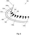
- Fig. 6 presents a schematic view of an embodiment of a capsule according to an aspect of the invention, wherein geometry of the capsule 150 and of the receptacle 108 are substantially the same as discussed with reference to Fig. 2 .
- the at least one projection is provided as a bridge between the surface 104a and the wall 102a.
- a plurality of bridges 147a, 147b, 147c, ..., 147n are provided.
- the bridge structure may be provided as an oblique link having a base portion 153 on the surface 104a and end portions terminating on the wall 102a.
- the bridge may be provided as a triangular or prismatic filling between the surface 104a and the wall 102a. In both cases the bridge may have two or more bifurcations 151, 152 having the same base and splitting and the wall 102a.
- base portion 153 is schematically depicted to be arranged near the rim/wall interface, it may be positioned substantially distanced from said interface. Also, it is possible, that different isolated bridge structures have differently positioned base portions. Alternatively, it is possible that a one circumferentially arranged bridge structure is provided connecting the rim surface 104a and the wall 102.
- Fig. 7 shows a schematic representation, in cross sectional view, of a second example of a system 1 discussed with reference to Fig. 1 for preparing a predetermined quantity of beverage suitable for consumption using an extractable product.
- the system 1 comprises an exchangeable capsule 2, and a beverage brewing device 4.
- the device 4 comprises a receptacle, here enclosing member 6, for holding the exchangeable capsule 2.
- the device 4 further comprises a support member 8 for supporting the capsule 2.
- a gap is drawn between the capsule 2, the enclosing member 6 and the support member 8 for clarity. It will be appreciated that, in use, the capsule 2 may lie in contact with the enclosing member 6 and the support member 8.
- the enclosing member 6 has a shape complementary to the shape of the capsule 2.
- the apparatus 4 further comprises a fluid dispensing device 10 for supplying an amount of a fluid, such as water, under a pressure, of e.g. 9 bars, to the exchangeable capsule 2.
- the exchangeable capsule 2 comprises a cup 12 and a lid 14.
- the cup 12 comprises a circumferential wall 16, a bottom 18 closing the circumferential wall 16 at a first end, and a flange-like rim 20 extending outwardly of the circumferential wall 16 at a second end opposite the bottom 18 wall.
- the circumferential wall 16, the bottom 18 and the lid 14 enclose an inner space 22 comprising the extractable product.
- the capsule is initially open.
- the capsule 2 comprises pre-made entrance openings 25.
- the entrance openings 25 may be through holes in the bottom 18.
- the capsule 2 comprises premade exit openings 27.
- the exit holes 27 may be through holes in a foil-like lid 14, e.g. manufactured from plastics material, or may be pores in a porous lid, e.g. manufactured from a non-woven material such as filter paper.
- the system 1 of Fig. 7 does not comprise bottom piercing means nor lid piercing means 26.
- the ridges 28.i are arranged on the flange-like rim 20.
- the ridges 28.i are arranged on the side of the flange-like rim 20 facing away from the lid 14. More generally put, the ridges 28.i extend outwardly of the cup 12.
- the ridges 28.i are made of the same material as the cup 12.
- the ridges 28.i are integral with the cup 12.
- the ridges 28.i may abut against a leading edge 30 of the enclosing member 6.
- at least one ridge 28.i abuts against at least a portion of the leading edge 30 of the enclosing member 6, a sealing engagement is obtained between the enclosing member 6 and the capsule 2 at the location where the at least one ridge 28.i abuts against at least the portion of the leading edge 30 of the enclosing member 6.
- the system 1 shown in Fig. 7 is operated as follows for preparing a cup of coffee, wherein the extractable product is roasted and ground coffee.
- the capsule 2 is placed in the enclosing member 6.
- the support member 8 is brought into contact with the capsule 2.
- the fluid here hot water under pressure, is supplied to the extractable product in the inner space 22 through the entrance opening 25.
- the water will wet the coffee grounds and extract the desired substances to form the coffee beverage.
- the pressure inside the capsule 2 may rise.
- the prepared coffee will drain from the capsule 2 through the exit openings 27 and outlets 32 of the support member 8, and may be supplied to a container such as a cup (not shown).
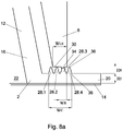
- Figs. 8a and 8b show an enlarged detail of a part of the system 1 according to the invention.
- four circumferential ridges 28.i are arranged on the flange-like rim 20.
- the ridges 28.i are integral with the rim 20.
- the ridges 28.i are arranged concentrically with respect to each other.
- the ridges 28.i are also arranged concentrically with an axis of the cup 12.
- the leading edge 30 of the enclosing member 6 comprises an irregularity in the form of a protrusion 34, e.g. a bulge, a burr or a lump (e.g. caked-on debris). It can be seen that in this example one particular ridge 28.3 of the ridges 28.i abuts the protrusion 34 and is locally more compressed. Hence, the ridges 28.i and the enclosing member 6 are in sealing engagement despite the presence of the protrusion 34.
- a protrusion 34 e.g. a bulge, a burr or a lump (e.g. caked-on debris).
- the leading edge 30 of the enclosing member 6 comprises an irregularity in the form of a recess 35 or depression, e.g. a dent, scratch or a crevice.
- a recess 35 or depression e.g. a dent, scratch or a crevice.
- one particular ridge 28.2 of the ridges 28.i faces the recess 35.
- a neighbouring ridge 28.3 will, accordingly, be locally more compressed and abut the leading edge 30 of the enclosing member 6.
- the ridges 28.i and the enclosing member 6 are in sealing engagement despite the presence of the recess 35.
- each of the ridges 28.i has a substantially triangular cross section. This provides the advantage that compression of the ridges 28.i requires a progressively increasing force. Hence, each ridge 28.i can easily follow the contour of the irregularity of the enclosing member 6.
- all ridges have substantially the same height H R prior to use, e.g. prior to being compressed.
- all ridges 28.i may equally contribute to the sealing engagement between the capsule 2 and the enclosing member 6.
- a misalignment between the capsule 2 and the enclosing member 6 may be tolerated, without the leading edge 30 failing to abut any ridge 28.i.
- each ridge 28.i has a maximum individual width W R that is less than the width W LE of the leading edge 30 of the enclosing member 6.
- each ridge 28.i is narrow relative to the leading edge 30, so that each ridge 28.i can easily be compressed by the leading edge 30.
- the plurality of ridges 28.i has a combined width W C that is larger than the width W LE of the leading edge 30 of the enclosing member 6.
- the width of individual members of the at least one protrusion may be less than the width of the portion of the receptacle arranged to interact with the capsule. It will also be appreciated that in general the width of the at least one protrusion may be larger than the width of the portion of the receptacle arranged to interact with the capsule.
- the width W R of each of the ridges 28.i is smaller than the height H R of that ridge prior to use.
- the ridges 28.i have a slender form, allowing easy deformation of the ridges 28.i, e.g. by compression of a top edge 36 of he ridges towards a base 38 of the ridges 28.i.
- the ridges 28.i may easily follow the irregularity in the enclosing member 6 at the location of the sealing engagement.
- the width W R of the ridge is measured parallel to the plane onto which the ridge is arranged and that the height H R of the ridge is measured orthogonal to the width.
- the width W R each of the ridges 28.i is less than a thickness H F of the flange-like rim 20.
- the height H R of each of the ridges 28.i prior to use is less than the thickness H F of the flange-like rim 20.
- a resistance against compression of the ridges 28.i may be less than a resistance against compression of the rim 20.
- the rim 20 will be rigid relative to the ridges 28.i, while the ridges 28.i may possess enough compressibility due to their shape and dimensions to provide the sealing engagement with the enclosing member 6 even if the enclosing member comprises the irregularity at the location of the sealing engagement.
- the ratio of the resistance against compression of the ridges 28.i to the resistance against compression of the rim 20 may be further improved by increasing the thickness of the rim 20 at least locally at the position of the ridges 28.i.
- the geometry of the ridges 28.i allows the ridges 28.i to adapt to an irregularity at the enclosing member 6, even if a material is chosen which allows the remainder of the cup 12 to be substantially rigid.
- Such substantially rigid cup 12 may increase the ease of handling of the capsule 2.
- the ridges 28.i are unitary with the flange-like rim 20, circumferential wall 16, and optionally the bottom 18, e.g. of a plastics material. It has been found that in such case the cup 12 may be substantially rigid, while the ridges 28.i may cooperate with the enclosing member 6 to provide the sealing engagement even if the chosen plastics material has a shore D hardness of 70 or more.
- the thickness of the rim 20 is approximately 0.2 mm.
- the width of the leading edge 30 of the enclosing member 6 is approximately 0.7 mm.
- the height H R of each of the ridges 28.i is approximately 0.2 mm prior to use.
- the height H R is more than 0.3 mm, more preferably more than 0.21 mm, it is also possible that the height H R is more than 0.15 mm prior to use.
- the maximum width W R of each of the ridges 28.i is approximately 0.14 mm.
- the width W R is more than 0.3 mm, more preferably more than 0.21 mm, most preferably more than 0.15 mm.
- the ridges 28.i are spaced radially such that two neighbouring ridges substantially abut radially. More in general, the radial distance between two neighbouring ridges 28.i is preferably less than the maximum width W R of the ridges 28.i, more preferably less than 50% of the maximum width W R , most preferably less than 25% of the maximum width W R . Thus, the ridges 28.i are spaced closely together, allowing a good chance that at least one of the ridges 28.i properly abuts against the leading edge 30 of the enclosing member 6.
- the closely spaced ridges 28.i allow for increased tolerance to misalignment of the capsule 2 with respect to the enclosing member 6, since the narrow space between the ridges 28.i may form a labyrinth providing sufficient resistance against fluid flow to provide a sufficient sealing engagement, even if not one single ridge 28.i fully abuts against the enclosing member 6.
- the ridges 28.i are integrally formed with the cup 12.
- the ensemble of the cup 12 and ridges 28.i may e.g. be injection moulded in one piece.
- the ensemble may be formed from a plastics material, such as for instance polypropylene.
- the material of the ridges 28.i is chosen to be plastically deformable.
- the ridges 28.i, at least the tops 36 of the ridges may be plastically deformed upon contact with the enclosing member 6.
- the plastically deforming ridges 28.i may easily adapt to an irregularity of the enclosing member 6 at the location of the sealing engagement.
- Figs. 8a and 8b may be applied to the system described in view of Fig. 1 as well as to the system described in view of Fig. 7 .
- Fig. 9 shows an enlarged detail of a part of an elaborate system 1 according to the invention.
- the capsule 2 comprises a further ridge 40.
- the further ridge 40 is arranged on the flange-like rim 20, on the side facing away from the lid 14.
- the further ridge 40 is integral with the flange-like rim 20.
- the further ridge 40 is substantially concentric with the ridges 28.i.
- the further ridge 40 is positioned circumscribing the ridges 28.i.
- a height H FR of the further ridge 40 is different from the height H R of the ridges 28.i.
- the height H FR of the further ridge 40 is larger than the height H R of the ridges 28.i.
- the further ridge 40 is arranged to abut against an outer circumferential surface 42 of the enclosing member 6.
- the outer circumferential surface 42 may be wedged against the inner circumferential surface 44 of the further ridge 40.
- the further ridge 40 may comprise a conical section 46 on the inner circumferential surface 44.
- the further ridge 40 may also be applied in the situations described with respect to Figs. 1 , 7 , 8a and 8b . It will be appreciated that the further ridge 40 may also be used in conjunction with any one of the protrusions discussed with respect to Figs. 2-6 .
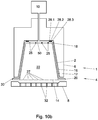
- Fig. 10a shows a schematic representation of a further example of a system 1 according to the invention.
- the system 1 shown in Fig. 10a is substantially identical to the system shown in Fig. 1 .
- the location of the at least one projection, here ridges 28.i, on the cup 12 is different.
- the at least one projection, here ridges 28.i is located on the circumferential side wall 16 of the cup 12.
- the at least one projection, here ridges 28.i abuts against an inner circumferential surface 48 of the enclosing member 6.
- the at least one projection, here ridges 28.i, and the inner circumferential surface 48 are in sealing engagement.
- the at least one projection, e.g. the ridges 28.i may be located on the circumferential side wall 16 of the cup 12.
- Fig. 10b shows a schematic representation of a further example of a system 1 according to the invention.
- the system 1 shown in Fig. 10b is substantially identical to the system shown in Fig. 7 .
- the location of the at least one projection, here the ridges 28.i, on the cup 12 is different.
- the at least one projection, here the ridges 28.i is located on the outer surface of the bottom 18 of the cup 12.
- the at least one projection, here ridges 28.i abuts against an inner back surface 50 of the enclosing member 6.
- the at least one projection, i.e. the ridges 28.i, and the inner back surface 50 are in sealing engagement.
- the at least one protrusion, e.g. the ridges 28.i may be located on the outer surface of the bottom 18 of the cup 12.
- FIG. 11 presents in a schematic way an embodiment of a further example of a capsule according to the invention.
- View 160 presents schematically a portion of an axial cross-section of the capsule according to a further aspect of the invention. It will be appreciated that general details not discussed with reference to this Figure may be found with reference to Figure 2 .
- the capsule 160 and the surface 109 of the receptacle in use form a substantially sealing engagement when the surface 109 of the receptacle 108 intercepts the elongated structures 164.
- the height of the flange-like rim 104 at a periphery of the capsule 160 near the outer ring 106 may be about 0.2 mm.
- the elongated structures 164 may be provided on a projection 162, which may be as high as 0.5 - 0.7 mm counting from the bottom surface 104a of the flange-like rim, see item H1.
- the elongated structures 164 may be about 0.25 mm high (see item h2) leading to a total elevation of the flange-like rim at this are to 0.8 - 1 mm.
- Fig. 12 presents in a schematic way an embodiment of a still further example of a capsule according to the invention. In this embodiment two variants are shown which may be used individually or in combination.
- the surface of the flange-like rim may be elevated as a whole to a level H3, which may be as high as 0.8 - 1.0 mm. It this way a substantially elevated projection is provided which may be seamlessly connected to the outer surface of the capsule 102a.
- the projection 104" is made of a substantially soft and deformable material. More preferably, the capsule is made from the same soft and deformable material whereby the projection 104" is inherently integrated with it. For example, such structure may be provided by suitable molding techniques.
- the elevated projection 104" may be provided with elongated projections 164" which may be provided as suitable grooved in the body of the projection 104. In this way local deforming properties of the projection are substantially increased as the elongated structures 164" may be deformed individually. It will be appreciated that the elongated structures may be provided on a portion of the elevated projection 104", or they may cover its whole lateral surface.
- Figure 13 presents schematically a top view of a suitable circumferential projection having an irregular shape.
- the projection 180 is arranged on the flange-like rim, in such a way that it runs across a path conceived to be occupied by a surface of the receptacle in use. It will be appreciated that a suitable plurality of variants of the shape of the projection 180 is possible, including zigzags, labyrinths and so forth. Also, a plurality of coherent irregular shapes a, b may be provided.
- the capsule as shown in Fig. 7 is used in the system of Fig. 1 . It is possible that in such instance the capsule is designed such that the bottom is not pierced by the bottom piercing means. It is also possible that the lid and the lid piercing means are designed such that the lid is not torn under the effect of fluid pressure in the inner space of the capsule.
- this leading edge may also comprise irregularities in the form of a plurality of radially extending grooves. Also in such case a sealing engagement may be obtained between the leading edge of the enclosing member and the ridges of the capsule according to the invention.
- the capsule is provided as a fillable or refillable capsule that can be filled or refilled by a user, respectively.
- Such capsule may be provided as a separate cup and lid that may be connected to the cup by the user after filling the capsule with a beverage ingredient.
- the lid may be partially, e.g. hingedly, connected to the cup so the user can connect the lid to substantially the entire perimeter of the flange-like rim after filling the cup with the beverage ingredient.
- the plurality of ridges comprises three or four ridges. It will be appreciated that also another number of ridges may be used, such as two, five or six ridges.
- any reference signs placed between parentheses shall not be construed as limiting the claim.
- the word 'comprising' does not exclude the presence of other features or steps then those listed in a claim.
- the words 'a' and 'an' shall not be construed as limited to 'only one', but instead are used to mean 'at least one', and do not exclude a plurality.
- the mere fact that certain measures are recited in mutually different claims does not indicate that a combination of these measures cannot be used to advantage.
Abstract
Description
- The invention relates to a capsule, a system and a method for preparing a predetermined quantity of beverage suitable for consumption using an extractable product.
- Systems for preparing a beverage, such as coffee, using a brewing device for supplying a liquid, such as water, under pressure to a capsule comprising a dose of a beverage ingredient are known. Commonly, the brewing device comprises a receptacle for receiving the capsule, such as an enclosing member for enclosing the capsule. In use a sealing engagement is provided between the capsule and the enclosing member, so as to prevent leaking of a liquid, e.g. water or the beverage. The sealing engagement is usually obtained by pressing the capsule and the enclosing member against each other along a circumferential line of contact.
- It is possible that the material of the enclosing member at the location of the sealing engagement, e.g. an elastomeric material, is softer than the material of the capsule at the location of the sealing engagement, e.g. aluminium. Such system is for instance known from
EP 1 203 554 - This disadvantage seems to be, at least partially, overcome by other known systems, wherein the material of the enclosing member at the location of the sealing engagement, e.g. a metal, is harder than the material of the capsule at the location of the sealing engagement, e.g. a plastics material. Such system is for instance known from
FR 2 617 389 - It is an object of the invention to at least partially meet at least one of the above disadvantages. In particular, it is an object of the invention to provide a capsule for preparing a predetermined quantity of beverage suitable for consumption using an extractable product conceived to be used in a beverage brewing device comprising a receptacle for interacting with the capsule, wherein there is has improved engagement between the capsule and the receptacle for mitigating possible leakages due to surface irregularities of the receptacle and/or the capsule.
- Thereto, according to the invention a capsule is provided for preparing a predetermined quantity of beverage suitable for consumption using an extractable product, by means of a beverage brewing device comprising a receptacle for receiving the capsule, comprising a cup comprising a circumferential wall, a bottom closing the circumferential wall at a first end, and a lid in use connected to the cup at a second end of the circumferential wall opposite the bottom, wherein the wall, bottom and lid, in use, enclose an inner space comprising the extractable product, and wherein at least a portion of a surface of the capsule conceived to, in use, interact with the receptacle is provided with at least one projection for forming a sealing engagement with the receptacle, wherein the capsule comprises a further ridge which is substantially concentrically enveloping the at least one projection, wherein a height of the further ridge is different from the height of the at least one projection.
- It is found that by providing local projections on a surface of the capsule in the area conceived to interact with the surface of the receptacle, surface irregularities of the latter may be efficiently mitigated. It will be appreciated that different type of surface irregularities may be envisaged, including, but not limited to, local recesses, local protrusions, cracks, bursts, local wear and so forth. Accordingly, the at least one projection may be provided on the surface of the capsule at a position wherein such irregularities have occurred or are likely to occur. The at least one projection may for instance be provided on the outer surface of the cup. In case the cup comprises a flange-like rim extending outwardly of the circumferential wall at the second end, the at least one projection may for instance be provided on the flange-like rim. The receptacle may be provided in the form of an enclosing member, which may be arranged to at least partially enclose the capsule, and may, in use, be pressed against the rim of the capsule. Due to the fact that the receptacle is usually manufactured from extruded plastic, minor manufacturing defects may occur. This may lead to further local irregularities of the outer surface of the receptacle conceived to engage with the flange-like rim of the capsule in use. Such further local irregularities may relate to recesses, i.e. local deepening of the outer surface of the receptacle or protrusions, i.e. local elevations of the outer surface of the receptacle.
- By providing the flange-like rim of the capsule with at least one projection conceived to interact with a surface of the receptacle in use, thereby forming a sealing engagement with the receptacle, the named irregularities may be mitigated.
- It will be appreciated that different types of a sealing engagement may be envisaged. For example, the at least one projection may be provided at an area of the capsule for achieving an abutment between the at least one projection and the surface of the receptacle conceived to interact with the capsule in use. It will be appreciated that those skilled in the art knowing a shape and a dimension of the outer surface of the receptacle conceived to come into contact with the capsule may readily appreciate at which region of the capsule the at least one projection is to be provided for forming said abutment.
- In an embodiment, the height of the further ridge may be larger than the height of the at least one projection.
- The further ridge may be arranged on a flange-like rim of the cup, on the side facing away from the lid. Here, the further ridge may be integral with the flange-like rim. The further ridge may be substantially concentric with the at least one projection. The further ridge may be arranged to abut against an outer circumferential surface of the receptacle of the brewing device which receptacle may be embodied as an enclosing. The outer circumferential surface of the enclosing member may be wedged against the inner circumferential surface of the further ridge.
- In an embodiment, the further ridge may comprise a conical section on an inner circumferential surface thereof.
- Such a conical section on the inner circumferential surface of the further ridge facilitates insertion of the enclosing member within the perimeter of the further ridge.
- Thus, the at least one projection abuts against the enclosing member, and additionally, the further ridge abuts against the enclosing member. Hence, an improved sealing engagement between the capsule and the enclosing member may be obtained.
In an embodiment of the capsule according to the invention the at least one projection is circumferential with respect to the flange-like rim. However, it will be appreciated that the thus formed circumferential projection may not necessarily be circular. An irregularly shaped circumferential projection adapted to cooperate with a surface of the receptacle is envisaged as well. Such irregularly shaped circumferential projection may still have a rotational symmetry. This embodiment will be discussed in more details with reference to Figures. - It is found that although the at least one projection may be provided on selective areas of the flange-like rim which are likely to have irregular surface, for example, on separate regions along a periphery of the flange-like rim, it is advantageous to provide the at least one projection as a circumferential structure so that a rotational symmetry is preserved for positioning the capsule in the receptacle of the beverage brewing device.
- In a still further embodiment of the capsule according to the invention the at least one projection comprises a body capable of retaining fluid.
- It is found to be particularly advantageous to select for the at least one projection conceived to form a sealing engagement with the receptacle a material, which is capable of retaining fluid. Due to this feature possible microscopic imperfections of the sealing engagement are effectively mitigated due to fluid absorption in the material of the projection. Preferably, for such material a sponge-like material is used.
- In a still further embodiment of the capsule according to the invention a plurality of elongated individual projections is provided, said projections forming a brush-like area.
It is found that a reliable sealing engagement can be achieved when a multi-body projection is envisaged, for example when a brush-like structure is provided on the flange-like rim of the capsule. This may have a reason that the elongated individual projections may be bent or be otherwise deformed by the receptacle without substantially influencing a spatial position of a neighbouring elongated projection. As a result, for example, when a surface of the receptacle conceived to come into contact with the capsule in use comprises a recess, such recess may be filled or be otherwise mitigated by one or a few elongated projections, for example, hairs, the neighbouring elongated projections being substantially not affected. - In a still further embodiment of the capsule according to the invention the elongated individual projections have different height.
It is found that local height differences of the surface of the receptacle may be effectively smoothed out when the individual elongated bodies of the brush-like structure have different height. Preferably, a basis height is selected for forming a sealing engagement when no surface irregularities of the receptacle are present. Some elongated bodies will have a greater height for mitigating local surface irregularities due to recesses. Preferably, height of the elongated individual projections is in the range of 0.1 - 2 mm, preferably in the range of 0.13 - 1 mm, more preferably in the range of 0.15-0.5 mm. It is found that good results have been achieved when the height of the elongated individual projections is about 0.25mm. Preferably such brush-like structure is provided on the flange-like rim of the capsule for mitigating substantial surface irregularities, like cracks, surface indentation, for example due to wear and so forth.
It will be further appreciated that the elongated bodies may be provided on a base structure, or, alternatively, the elongated bodies may be formed as a set of grooves formed on an elevated base. Also in this case a height of the elongated structures, measured at their tops, is in the range of 0.1 - 2 mm, preferably in the range of 0.13 - 1 mm, more preferably in the range of 0.15-0.5 mm. It will be appreciated that such height may be measured with respect to a base surface of the flange-like rim of the capsule. This embodiment will be discussed in more detail with reference to Figures.
It will be further appreciated that such elongated structures may be formed from a material capable of deforming. In an extreme situation an elongated structure may be capable of being substantially fully flattened. The elongated structures may have a triangular, a circular or any other suitable cross-section.
In an alternative embodiment, the projection arranged on the flange-like rim may be substantially flat having a height in the range of 0.8 - 1.0 mm, whereas the projection is preferably formed from a soft material capable of deforming. Those skilled in the art will readily appreciate which class of materials, preferably plastics may be used for implementing such projection. In a still further embodiment of the capsule according to the invention the at least one projection comprises a textured material. - This technical measure is based on the insight that minor surface irregularities may be mitigated by providing the at least one projection having a modulated surface, like texture. The modulated surface may comprise a mixture of regularly spaced depressions and elevated areas. Preferably, a height difference between the elevated areas and the depressed areas being at least 0,05 mm, preferably at least 0.15 mm. It is found that such embodiment is effective for providing adequate sealing engagement between the flange-like rim and the surface of the receptacle when the latter comprises recesses and/or protrusions.
- In a still further embodiment of the capsule according to the invention the at least one projection comprises a plurality of interconnected tubular structures.
- It is found that such embodiment advantageously combines features of a material capable of retaining fluid and a material capable of individual deformation, like a brush. Preferably, the plurality of interconnected tubular structures comprises polygonal structures, such as honeycomb structures. When interacting with the surface of the receptacle having either a protrusion or a depression, the array of tubular structures may deform locally substantially matching geometry of the local irregularity (depression or protrusion). Preferably, a height of the tubular structure is selected so that the array of the tubular structures is at least slightly compressed when being in contact with the surface of the receptacle for forming a sealing engagement.
- In a still further embodiment of the capsule according to the invention the at least one projection comprises an oblique bridge extending between the flange-like rim and the wall.
- This technical measure is based on the insight that leakages may occur in the area where a vertical capsule wall contacts the substantially horizontal and flat flange-like rim. In order to provide a sealing engagement with the receptacle in use, the flange-like rim is provided with an oblique structure which can act as a fitting between the receptacle and otherwise substantially rectangular geometry of the wall/rim interface.
- It will be appreciated that the bridge structure may be provided along the whole circumference of the rim adjacent the wall, or, alternatively a suitable number of isolated bridge elements may be provided.
- In a still further embodiment of the capsule the bridge comprises two or more branches deviating from a base portion attached to the flange-like rim.
- It is found that by providing two deviating branches it is possible to achieve a further flexibility in accommodating local surface irregularities of the receptacle.
- In a still further embodiment of the capsule the at least one projection is flexible. Preferably, at least one projection is elastically deformable.
- In a still further embodiment of the capsule the at least one projection comprises a circumferential ridge. It has been found that such circumferential ridge may e.g. be subject to local deformation in order to adapt to any irregularities in the surface of the receptacle. Preferably, the at least one projection comprises a plurality of circumferential ridges.
- For example, the capsule may be provided with a cup comprising a circumferential wall, a bottom closing the circumferential wall at a first end, and a flange-like rim extending outwardly of the circumferential wall at a second end opposite the bottom, and a lid in use connected to the flange-like rim, wherein the wall, bottom and lid, in use, enclose an inner space comprising the extractable product, and wherein the cup further comprises a plurality of substantially concentric circumferential ridges extending outwardly of the cup, wherein the ridges are made of the same material as the cup.
- In use, at least one of the circumferential ridges may abut against at least a portion of the enclosing member, such that the sealing engagement is formed between, e.g. the top of, at least one of the ridges and the at least one portion of the receptacle, such as the enclosing member. Since the plurality of ridges is provided, a misalignment between the capsule and the enclosing member may be allowed while still obtaining the sealing engagement.
- It is possible that in general the at least one projection is made of the same material as the cup. Hence, a relatively cheap at least one projection may be provided.
- Preferably, the at least one projection, e.g. the ridge or ridges, is arranged on the flange-like rim, e.g. on the side of the flange-like rim facing away from the lid. Hence, the at least one projection, e.g. the ridge or ridges, may abut against a leading edge of the enclosing member. Thus, the sealing engagement may be formed at the location of the flange-like rim.
- It is possible that the at least one projection, e.g. the ridge or ridges, is integral with the flange-like rim. Thus manufacture of the cup may include manufacture of the at least one projection, e.g. the ridge or ridges, e.g. by injection moulding the ensemble of the cup and the at least one projection, e.g. the ridge or ridges. Hence, easy manufacture of the cup of the capsule may be obtained.
- In one embodiment, each ridge of the plurality of ridges has substantially the same height prior to use. Hence, each of the ridges of the plurality of ridges may contribute to the sealing engagement between the capsule and the enclosing member. Optionally, each ridge of the plurality of ridges has substantially the same width.
- It is possible that a width of a ridge, of the plurality of ridges is smaller than a height of that ridge. Preferably this applies to each ridge of the plurality of ridges. Hence the ridge has a slender form, allowing easy deformation of the ridge, e.g. by compression of a top edge of he ridge towards a base of the ridge. Hence, the ridge may easily follow an irregularity of the enclosing member at the location of the sealing engagement, e.g. a dent and/or a protrusion at the leading edge of the enclosing member.
- Preferably, a ridge of the plurality of the ridges has a width that is equal to or less than a thickness of the flange-like rim. Preferably, a ridge of the plurality of ridges has a height that is equal to or less than a thickness of the flange-like rim. Preferably this applies to each ridge of the plurality of ridges. Hence, a resistance of the ridge against compression may be less than a resistance against compression of the rim. Thus, the rim may be rigid relative to the ridge, while the ridge may possess enough compressibility due to its shape and/or dimensions to provide the sealing engagement with the enclosing member even if the enclosing member comprises an irregularity at the location of the sealing engagement.
- It is possible that a ridge of the plurality of ridges has a height of more than 0.3 mm, preferably more than 0.21 mm, more preferably more than 0.15 mm. It is also possible that a ridge of the plurality of ridges has a maximum width of more than 0.3 mm, preferably more than 0.21 mm, more preferably more than 0.15 mm. Preferably, this applies to each ridge of the plurality of ridges. These dimensions have been found to provide good sealing engagement between the ridge and the enclosing member.
- In an embodiment, a ridge of the plurality of ridges has a tapered, e.g. a substantially triangular, cross section. Preferably this applies to each ridge of the plurality of ridges. This provides the advantage that compression of the ridge requires a progressively increasing force. Hence, the ridge can easily follow the contour of an irregularity of the enclosing member since this will exert a locally increased force on the ridge.
- Preferably all ridges of the plurality of ridges have the same cross sectional shape.
- In an embodiment, a radial distance between two neighbouring ridges is less than a maximum width of the ridges, preferably less than 50% of the maximum width, more preferably less than 25% of the maximum width. Thus, the ridges are spaced closely together, allowing a good chance that at least one of the ridges properly abuts against the enclosing member, while still allowing ample space for the ridges to widen due to compression. Also, the closely spaced ridges allow for increased tolerance to misalignment of the capsule with respect to the enclosing member, since the narrow space between the ridges may form a labyrinth providing sufficient resistance against fluid flow to provide a sufficient sealing engagement between the capsule and the enclosing member, even if not one single ridge fully abuts against the enclosing member.
- Preferably, the lid is connected to the flange-like rim and the inner space is at least partially filled with the extractable product. Hence, the capsule ready for use is provided. The capsule may be hermetically closed, e.g. so as to improve shelf life of the capsule. Alternatively, the lid and/or bottom is porous and/or comprises openings for allowing a liquid to enter and/or exit the inner space.
- In an embodiment, the capsule is disposable. The disposable capsule is designed and intended to be disposed after single use. Thus, problems associated with hygiene, e.g. microbial growth, may be minimised.
- Preferably, the capsule is designed for preparing a single serving of the beverage.
- The invention also relates to a system for preparing a predetermined quantity of beverage suitable for consumption using an extractable product, comprising i) a capsule according to the invention; and ii) a beverage brewing device comprising a receptacle for interacting with the capsule, e.g. an enclosing member for enclosing the capsule, wherein, in use, the at least one projection, e.g. at least one of the ridges, abuts against at least a portion of the receptacle, e.g. enclosing member, such that a sealing engagement between the capsule and the receptacle, e.g. enclosing member, is formed.
- In an embodiment at least a portion of a leading edge of the enclosing member is arranged to abut against at least one of the ridges. Herein the ridges may be arranged on the flange-like rim of the capsule.
- Preferably, the ridges each have an individual width that is less than the width of the leading edge of the enclosing member. This provides the advantage that the ridges are narrow relative to the leading edge of the enclosing member. Thus, the ridges may easily adapt to a, e.g. small, irregularity, such as a dent, scratch, crevice and/or protrusion, on the leading edge of the enclosing member.
- Preferably, the plurality of ridges has a combined width that is larger than the width of the leading edge of the enclosing member. Hence, considerable tolerance for misalignment of the capsule with respect to the leading edge of the enclosing member is provided.
- It is possible that a ridge of the plurality of ridges has a height that is less than the width of the leading edge of the enclosing member. Preferably this applies to each ridge of the plurality of ridges. Thus, the ridge has a small height relative to the width of the leading edge of the enclosing member. This may prevent buckling of the ridges so that good sealing engagement between the leading edge of the enclosing member and the ridges may be obtained.
- The invention also relates to a method for preparing a predetermined quantity of beverage suitable for consumption using a system according to the invention.
- These and other aspects of the invention will be discussed in more detail with reference to drawings, wherein like reference numerals refer to like elements. It will be appreciated that the drawings are presents for illustrative purposes and may not be used for limiting the scope of the appended claims.
- The invention will now be further elucidated by means of, nonlimiting, examples referring to the drawing, in which
-
Fig. 1 shows a schematic representation of a first example of a system according to the invention. -
Fig. 2 presents a schematic view of an embodiment of a capsule according to an aspect of the invention. -
Fig. 3 presents a schematic view of an embodiment of a capsule according to an aspect of the invention. -
Fig. 4 presents a schematic view of an embodiment of a capsule according to an aspect of the invention; -
Fig. 5 presents a schematic view of an embodiment of a capsule according to an aspect of the invention. -
Fig. 6 presents a schematic view of an embodiment of a capsule according to an aspect of the invention. -
Fig. 7 shows a schematic representation of a second example of a system according to the invention; -
Fig. 8a shows an enlarged detail of a part of the system according to the invention; -
Fig. 8b shows an enlarged detail of a part of the system according to the invention; -
Fig. 9 shows an enlarged detail of a part of the system according to the invention; -
Fig. 10a shows a schematic representation of a further example of a system according to the invention; and -
Fig. 10b shows a schematic representation of an even further example of a system according to the invention. -
Fig. 11 presents in a schematic way an embodiment of a further example of a capsule according to the invention. -
Fig. 12 presents in a schematic way an embodiment of a still further example of a capsule according to the invention. -
Fig.13 presents in a schematic way a top view of an embodiment of a circumferential projection. -
Fig. 1 shows a schematic representation, in cross sectional view, of a first example of asystem 1 for preparing a predetermined quantity of beverage suitable for consumption using an extractable product. Thesystem 1 comprises anexchangeable capsule 2, and abeverage brewing device 4. Thedevice 4 comprises a receptacle in the form of an enclosingmember 6 for holding theexchangeable capsule 2. In this example, thedevice 4 further comprises asupport member 8 for supporting thecapsule 2. - In
Fig. 1 a gap is drawn between thecapsule 2, the enclosingmember 6 and thesupport member 8 for clarity. It will be appreciated that, in use, thecapsule 2 may lie in contact with the enclosingmember 6 and thesupport member 8. Commonly, the enclosingmember 6 has a shape complementary to the shape of thecapsule 2. Theapparatus 4 further comprises afluid dispensing device 10 for supplying an amount of a fluid, such as water, under a pressure, of e.g. 9 bars, to theexchangeable capsule 2. - In the example shown in
Fig. 1 , theexchangeable capsule 2 comprises acup 12 and alid 14. In this example, thecup 12 comprises acircumferential wall 16, a bottom 18 closing thecircumferential wall 16 at a first end, and a flange-like rim 20 extending outwardly of thecircumferential wall 16 at a second end opposite the bottom 18 wall. Thecircumferential wall 16, the bottom 18 and thelid 14 enclose aninner space 22 comprising the extractable product. In this example, the capsule is initially sealed, i.e. is hermetically closed prior to use. - The
system 1 ofFig. 1 comprises bottom piercing means 24 for piercing the bottom 18 of thecapsule 2 for creating at least oneentrance opening 25 in the bottom 18 for supplying the fluid to the extractable product through theentrance opening 25. - The
system 1 ofFig. 1 further comprises lid piercing means 26, here embodied as protrusions of thesupport member 8, for piercing thelid 14 of thecapsule 2. The lid piercing means 26 may be arranged to tear thelid 14 once a (fluid) pressure inside theinner space 22 exceeds a threshold pressure and presses thelid 14 against the lid piercing means 26 with sufficient force. Thelid 14 may e.g. comprise a tearable foil, e.g. made of aluminium. - In this example, the
cup 12 further comprises a plurality of projections in the form of substantially concentric circumferential ridges 28.i (i=1,2,3). In this example, the ridges 28.i are arranged on the flange-like rim 20. Here the ridges 28.i are arranged on the side of the flange-like rim 20 facing away from thelid 14. More generally put, the ridges 28.i extend outwardly of thecup 12. In this example the ridges 28.i are made of the same material as thecup 12. In this example, the ridges 28.i are integral with thecup 12. - As can be seen from
Fig. 1 , in use the ridges 28.i may abut against a leadingedge 30 of the enclosingmember 6. When in this example at least one ridge 28.i abuts against at least a portion of the leadingedge 30 of the enclosingmember 6, a sealing engagement is obtained between the enclosingmember 6 and thecapsule 2 at the location where the at least one ridge 28.i abuts against at least the portion of the leadingedge 30 of the enclosingmember 6. - The
system 1 shown inFig. 1 is operated as follows for preparing a cup of coffee, wherein the extractable product is roasted and ground coffee. - The
capsule 2 is placed in the enclosingmember 6. Thesupport member 8 is brought into contact with thecapsule 2. The bottom piercing means 24 pierce the bottom 18 of thecapsule 2 for creating theentrance openings 25. The fluid, here hot water under pressure, is supplied to the extractable product in theinner space 22 through theentrance openings 25. The water will wet the coffee grounds and extract the desired substances to form the coffee beverage. - During supplying the water under pressure to the
inner space 22, the pressure inside thecapsule 2 will rise. The rise in pressure will cause thelid 14 to deform and be pressed against the lid piercing means 26. Once the pressure reaches a certain level, the tear strength of thelid 14 will be surpassed and the lid will rupture against the lid piercing means 26, creating exit openings. The prepared coffee will drain from thecapsule 2 through the exit openings andoutlets 32 of thesupport member 8, and may be supplied to a container such as a cup (not shown). -
Fig. 2 presents a schematic view of another embodiment of a capsule according to an aspect of the invention. In this figure a schematic vertical cross-section of a portion of the capsule is shown. Thecapsule 110 comprises awall 102 having aninner surface 102b conceived to define at least a portion of the inner space I for accommodating the extractable product. Theouter surface 102a of the capsule may be orthogonally or obliquely arranged with respect to the flange-like rim 104. The flange-like rim 104 comprises anupper surface 104a conceived to undergo interaction with asurface 109 of areceptacle 108 of the beverage brewing device. The flange-like rim 104 may have a substantially flat portion between the base of thewall 102a and aterminal ring 106. Theterminal ring 106 may be provided to centre thereceptacle 108 with respect to the capsule. It will be appreciated that thereceptacle 108 may be shaped to receive thecapsule 110 so that theportion 108 substantially envelopes it. - In accordance with an aspect of the invention in order to form a sealing engagement between the
capsule 110 and thesurface 109 of the receptacle in use, a portion of thesurface 104a is provided with aprojection 107. It will be appreciated that theprojection 107 may be arranged substantially anywhere along width L of the flange-like rim. Also the way theprojection 107 is used for forming a sealing engagement may be different. - First, the
projection 107 may be arranged in an area wherein thewall 102 intercepts the flange-like rim 104 so that thesurface 109 substantially abuts theprojection 107. This has an advantage that the projection may be slightly compressed so that local surface irregularities of thereceptacle 108 are mitigated. For example, when for the projection a material is selected capable of retaining fluid, microscopic leakages from the rim-receptacle interface may be counteracted. - Secondly, the
projection 107, for example the sponge-like body, may be arranged close to theouter ring 106 so that it may next to abutting thesurface 109 of the receptacle also engage with a vertical outer surface of it. In this case the sponge-like projection may provide an improved sealing engagement as the outermost surface of thereceptacle 108 may be at least partially enveloped by the sponge-like body 107. -
Fig. 3 presents a schematic view of an embodiment of a capsule according to an aspect of the invention, wherein geometry of thecapsule 120 and of thereceptacle 108 are substantially the same as discussed with reference toFig. 2 . - In this particular embodiment the projection comprises a plurality of individual
elongated members 117, wherein the individual elongated members may have the same height or may have different heights h1, h2. It will be appreciated that various embodiments of the individual elongated members are envisaged. First, the members may be provided as a brush-like structure, which may be adhered to thesurface 104a using a suitable adhesive. The individual members may be manufactured from plastic, synthetic hair or the like. The individual members may e.g. be made of the same material as thecup projection 117 may be provided as a circumferential structure along a periphery of the capsule's rim. Preferably, the circumferential structure is concentric with a rotational axis of the capsule (not shown). Also, more than one circumferentially arrangedprojections 117 may be provided. For example, one circumferential projection may be provided at or near a rim-wall interface and a second circumferential projection may be provided at a rim/ring interface thereby providing a second barrier for possible microscopic leakages. Additionally or alternatively, theprojection 117 may be provided as a number of isolated islands along thesurface 104a. Such islands may be provided in a two-dimensional pattern, e.g. a chequered pattern, or they may be provided along other suitable pattern. In the example ofFig. 3 , the individual members are drawn as being straight. It will be appreciated that tit is also possible that the individual members are curved or curled. It will be appreciated that the members may be intertwined e.g. forming a fleece-like structure. Such fleece-like structure may be injection moulded together with the cup. -
Fig. 4 presents a schematic view of an embodiment of a capsule according to an aspect of the invention, wherein geometry of thecapsule 130 and of thereceptacle 108 are substantially the same as discussed with reference toFig. 2 . - In this particular embodiment the at least one projection comprises a
textured material 127, which may be provided anywhere along width L of thesurface 104a. Also in this case theprojection 127 may be provided as one or more circumferential structures or as individual regions. Thematerial 127 preferably comprises depressions and projections. Preferably, a height difference between adjacent depressions and projections is at least about 0.5 mm. -
Fig. 5 presents a schematic view of an embodiment of a capsule according to an aspect of the invention, wherein geometry of thecapsule 140b and of thereceptacle 108 are substantially the same as discussed with reference toFig. 2 . - In a
top view 140a a capsule portion is depicted wherein on thesurface 104a between thering 106 and thewall 102a a projection is provided comprising a number of interconnected tubular structures. Although in this particular example honeycomb tubular structures are shown any cross-sectional shape is possible. A polygonal cross-section may be preferred as any tubular structure is connected to a plurality of adjacent tubular structures increasing flexibility of such projection in a vertical direction V. - The tubular structure may be provided along a circumference of the
surface 104a, or it may be provided at selected regions. The projection comprising hollow tubular bodies may have an advantage that these bodies may easily be compressed by the receptacle (not shown) for forming the sealing engagement. Inner volume of the tubular bodies may be used as microscopic vessels for receiving fluid escaping from the sealing engagement, which may further improve the sealing engagement. -
Fig. 6 presents a schematic view of an embodiment of a capsule according to an aspect of the invention, wherein geometry of thecapsule 150 and of thereceptacle 108 are substantially the same as discussed with reference toFig. 2 . - In this particular embodiment the at least one projection is provided as a bridge between the
surface 104a and thewall 102a. Preferably a plurality ofbridges base portion 153 on thesurface 104a and end portions terminating on thewall 102a. Alternatively, the bridge may be provided as a triangular or prismatic filling between thesurface 104a and thewall 102a. In both cases the bridge may have two ormore bifurcations wall 102a. It will further be appreciated that although thebase portion 153 is schematically depicted to be arranged near the rim/wall interface, it may be positioned substantially distanced from said interface. Also, it is possible, that different isolated bridge structures have differently positioned base portions. Alternatively, it is possible that a one circumferentially arranged bridge structure is provided connecting therim surface 104a and thewall 102. -
Fig. 7 shows a schematic representation, in cross sectional view, of a second example of asystem 1 discussed with reference toFig. 1 for preparing a predetermined quantity of beverage suitable for consumption using an extractable product. Thesystem 1 comprises anexchangeable capsule 2, and abeverage brewing device 4. Thedevice 4 comprises a receptacle, here enclosingmember 6, for holding theexchangeable capsule 2. In this example, thedevice 4 further comprises asupport member 8 for supporting thecapsule 2. - In
Fig. 7 a gap is drawn between thecapsule 2, the enclosingmember 6 and thesupport member 8 for clarity. It will be appreciated that, in use, thecapsule 2 may lie in contact with the enclosingmember 6 and thesupport member 8. Commonly, the enclosingmember 6 has a shape complementary to the shape of thecapsule 2. Theapparatus 4 further comprises afluid dispensing device 10 for supplying an amount of a fluid, such as water, under a pressure, of e.g. 9 bars, to theexchangeable capsule 2. - In the example shown in
Fig. 7 , theexchangeable capsule 2 comprises acup 12 and alid 14. In this example, thecup 12 comprises acircumferential wall 16, a bottom 18 closing thecircumferential wall 16 at a first end, and a flange-like rim 20 extending outwardly of thecircumferential wall 16 at a second end opposite the bottom 18 wall. Thecircumferential wall 16, the bottom 18 and thelid 14 enclose aninner space 22 comprising the extractable product. In this example, the capsule is initially open. Hence, thecapsule 2 comprisespre-made entrance openings 25. Theentrance openings 25 may be through holes in the bottom 18. Further, thecapsule 2 comprises premadeexit openings 27. The exit holes 27 may be through holes in a foil-like lid 14, e.g. manufactured from plastics material, or may be pores in a porous lid, e.g. manufactured from a non-woven material such as filter paper. - The
system 1 ofFig. 7 does not comprise bottom piercing means nor lid piercing means 26. - In this example, the
cup 12 further comprises a plurality of substantially concentric circumferential ridges 28.i (i=1,2,3,...). In this example, the ridges 28.i are arranged on the flange-like rim 20. Here the ridges 28.i are arranged on the side of the flange-like rim 20 facing away from thelid 14. More generally put, the ridges 28.i extend outwardly of thecup 12. In this example the ridges 28.i are made of the same material as thecup 12. In this example, the ridges 28.i are integral with thecup 12. - As can be seen from
Fig. 7 , in use the ridges 28.i may abut against a leadingedge 30 of the enclosingmember 6. When in this example at least one ridge 28.i abuts against at least a portion of the leadingedge 30 of the enclosingmember 6, a sealing engagement is obtained between the enclosingmember 6 and thecapsule 2 at the location where the at least one ridge 28.i abuts against at least the portion of the leadingedge 30 of the enclosingmember 6. - The
system 1 shown inFig. 7 is operated as follows for preparing a cup of coffee, wherein the extractable product is roasted and ground coffee. - The
capsule 2 is placed in the enclosingmember 6. Thesupport member 8 is brought into contact with thecapsule 2. The fluid, here hot water under pressure, is supplied to the extractable product in theinner space 22 through theentrance opening 25. The water will wet the coffee grounds and extract the desired substances to form the coffee beverage. - During supplying the water under pressure to the
inner space 22, the pressure inside thecapsule 2 may rise. The prepared coffee will drain from thecapsule 2 through theexit openings 27 andoutlets 32 of thesupport member 8, and may be supplied to a container such as a cup (not shown). -
Figs. 8a and8b show an enlarged detail of a part of thesystem 1 according to the invention. In this example four circumferential ridges 28.i are arranged on the flange-like rim 20. Here, the ridges 28.i are integral with therim 20. In this example the ridges 28.i are arranged concentrically with respect to each other. In this example the ridges 28.i are also arranged concentrically with an axis of thecup 12. - In
Fig. 8a the leadingedge 30 of the enclosingmember 6 comprises an irregularity in the form of aprotrusion 34, e.g. a bulge, a burr or a lump (e.g. caked-on debris). It can be seen that in this example one particular ridge 28.3 of the ridges 28.i abuts theprotrusion 34 and is locally more compressed. Hence, the ridges 28.i and the enclosingmember 6 are in sealing engagement despite the presence of theprotrusion 34. - In
Fig. 8b the leadingedge 30 of the enclosingmember 6 comprises an irregularity in the form of arecess 35 or depression, e.g. a dent, scratch or a crevice. It can be seen that in this example one particular ridge 28.2 of the ridges 28.i faces therecess 35. A neighbouring ridge 28.3 will, accordingly, be locally more compressed and abut the leadingedge 30 of the enclosingmember 6. Hence, the ridges 28.i and the enclosingmember 6 are in sealing engagement despite the presence of therecess 35. - In the examples of
Figs. 8a and8b , each of the ridges 28.i has a substantially triangular cross section. This provides the advantage that compression of the ridges 28.i requires a progressively increasing force. Hence, each ridge 28.i can easily follow the contour of the irregularity of the enclosingmember 6. - In the examples of
Figs. 8a and8b , all ridges have substantially the same height HR prior to use, e.g. prior to being compressed. Hence, all ridges 28.i may equally contribute to the sealing engagement between thecapsule 2 and the enclosingmember 6. Hence, a misalignment between thecapsule 2 and the enclosingmember 6 may be tolerated, without the leadingedge 30 failing to abut any ridge 28.i. - In the examples of
Figs. 8a and8b the ridges 28.i each have a maximum individual width WR that is less than the width WLE of the leadingedge 30 of the enclosingmember 6. Thus, each ridge 28.i is narrow relative to the leadingedge 30, so that each ridge 28.i can easily be compressed by the leadingedge 30. Further, here the plurality of ridges 28.i has a combined width WC that is larger than the width WLE of the leadingedge 30 of the enclosingmember 6. Hence, a misalignment between thecapsule 2 and the enclosingmember 6 may be tolerated, without the leadingedge 30 failing to abut any ridge 28.i. It will be appreciated that in general the width of individual members of the at least one protrusion may be less than the width of the portion of the receptacle arranged to interact with the capsule. It will also be appreciated that in general the width of the at least one protrusion may be larger than the width of the portion of the receptacle arranged to interact with the capsule. - In these examples, the width WR of each of the ridges 28.i is smaller than the height HR of that ridge prior to use. Hence the ridges 28.i have a slender form, allowing easy deformation of the ridges 28.i, e.g. by compression of a
top edge 36 of he ridges towards abase 38 of the ridges 28.i. Hence, the ridges 28.i may easily follow the irregularity in the enclosingmember 6 at the location of the sealing engagement. It is noted that herein the width WR of the ridge is measured parallel to the plane onto which the ridge is arranged and that the height HR of the ridge is measured orthogonal to the width. - In these examples, the width WR each of the ridges 28.i is less than a thickness HF of the flange-
like rim 20. Also in these examples, the height HR of each of the ridges 28.i prior to use is less than the thickness HF of the flange-like rim 20. Hence, a resistance against compression of the ridges 28.i may be less than a resistance against compression of therim 20. In these examples therim 20 will be rigid relative to the ridges 28.i, while the ridges 28.i may possess enough compressibility due to their shape and dimensions to provide the sealing engagement with the enclosingmember 6 even if the enclosing member comprises the irregularity at the location of the sealing engagement. It will be appreciated that the ratio of the resistance against compression of the ridges 28.i to the resistance against compression of therim 20 may be further improved by increasing the thickness of therim 20 at least locally at the position of the ridges 28.i. - The geometry of the ridges 28.i allows the ridges 28.i to adapt to an irregularity at the enclosing
member 6, even if a material is chosen which allows the remainder of thecup 12 to be substantially rigid. Such substantiallyrigid cup 12 may increase the ease of handling of thecapsule 2. It is for instance possible that the ridges 28.i are unitary with the flange-like rim 20,circumferential wall 16, and optionally the bottom 18, e.g. of a plastics material. It has been found that in such case thecup 12 may be substantially rigid, while the ridges 28.i may cooperate with the enclosingmember 6 to provide the sealing engagement even if the chosen plastics material has a shore D hardness of 70 or more. - In these examples, the thickness of the
rim 20 is approximately 0.2 mm. In these examples, the width of the leadingedge 30 of the enclosingmember 6 is approximately 0.7 mm. In these examples the height HR of each of the ridges 28.i is approximately 0.2 mm prior to use. Preferably the height HR is more than 0.3 mm, more preferably more than 0.21 mm, it is also possible that the height HR is more than 0.15 mm prior to use. In these examples the maximum width WR of each of the ridges 28.i is approximately 0.14 mm. Preferably, the width WR is more than 0.3 mm, more preferably more than 0.21 mm, most preferably more than 0.15 mm. These dimensions have been found to provide good sealing engagement between the ridges 28.i and the enclosingmember 6. - In the examples of
Figs. 8a and8b the ridges 28.i are spaced radially such that two neighbouring ridges substantially abut radially. More in general, the radial distance between two neighbouring ridges 28.i is preferably less than the maximum width WR of the ridges 28.i, more preferably less than 50% of the maximum width WR, most preferably less than 25% of the maximum width WR. Thus, the ridges 28.i are spaced closely together, allowing a good chance that at least one of the ridges 28.i properly abuts against the leadingedge 30 of the enclosingmember 6. Also, the closely spaced ridges 28.i allow for increased tolerance to misalignment of thecapsule 2 with respect to the enclosingmember 6, since the narrow space between the ridges 28.i may form a labyrinth providing sufficient resistance against fluid flow to provide a sufficient sealing engagement, even if not one single ridge 28.i fully abuts against the enclosingmember 6. - In a preferred embodiment according to
Fig. 8a orFig. 8b , the ridges 28.i are integrally formed with thecup 12. The ensemble of thecup 12 and ridges 28.i may e.g. be injection moulded in one piece. The ensemble may be formed from a plastics material, such as for instance polypropylene. - In a preferred embodiment the material of the ridges 28.i is chosen to be plastically deformable. Preferably, the ridges 28.i, at least the tops 36 of the ridges may be plastically deformed upon contact with the enclosing
member 6. The plastically deforming ridges 28.i may easily adapt to an irregularity of the enclosingmember 6 at the location of the sealing engagement. - It will be appreciated that the details of
Figs. 8a and8b may be applied to the system described in view ofFig. 1 as well as to the system described in view ofFig. 7 . -
Fig. 9 shows an enlarged detail of a part of anelaborate system 1 according to the invention. In this example, in addition to the plurality of ridges 28.i, thecapsule 2 comprises a further ridge 40. - In
Fig. 9 the further ridge 40 is arranged on the flange-like rim 20, on the side facing away from thelid 14. Here, the further ridge 40 is integral with the flange-like rim 20. In this example, the further ridge 40 is substantially concentric with the ridges 28.i. Here the further ridge 40 is positioned circumscribing the ridges 28.i. It will be noted that a height HFR of the further ridge 40 is different from the height HR of the ridges 28.i. In this example, the height HFR of the further ridge 40 is larger than the height HR of the ridges 28.i. - In this example, the further ridge 40 is arranged to abut against an outer
circumferential surface 42 of the enclosingmember 6. The outercircumferential surface 42 may be wedged against the innercircumferential surface 44 of the further ridge 40. In order to facilitate insertion of the enclosingmember 6 within the perimeter of the further ridge 40, the further ridge 40 may comprise aconical section 46 on the innercircumferential surface 44. - Thus, in this example at least one of the ridges 28.i abuts against the enclosing
member 6, and additionally, the further ridge 40 abuts against the enclosingmember 6. Hence, an improved sealing engagement between thecapsule 2 and the enclosingmember 6 may be obtained. - It will be appreciated that the further ridge 40 may also be applied in the situations described with respect to
Figs. 1 ,7 ,8a and8b . It will be appreciated that the further ridge 40 may also be used in conjunction with any one of the protrusions discussed with respect toFigs. 2-6 . -
Fig. 10a shows a schematic representation of a further example of asystem 1 according to the invention. Thesystem 1 shown inFig. 10a is substantially identical to the system shown inFig. 1 . InFig. 10a , however, the location of the at least one projection, here ridges 28.i, on thecup 12 is different. In this example, the at least one projection, here ridges 28.i, is located on thecircumferential side wall 16 of thecup 12. Here, the at least one projection, here ridges 28.i, abuts against an innercircumferential surface 48 of the enclosingmember 6. InFig. 10a the at least one projection, here ridges 28.i, and the innercircumferential surface 48 are in sealing engagement. It will be appreciated that also in the system shown inFigs. 2-7 the at least one projection, e.g. the ridges 28.i, may be located on thecircumferential side wall 16 of thecup 12. -
Fig. 10b shows a schematic representation of a further example of asystem 1 according to the invention. Thesystem 1 shown inFig. 10b is substantially identical to the system shown inFig. 7 . InFig. 10b , however, the location of the at least one projection, here the ridges 28.i, on thecup 12 is different. In this example, the at least one projection, here the ridges 28.i, is located on the outer surface of the bottom 18 of thecup 12. Here, the at least one projection, here ridges 28.i, abuts against aninner back surface 50 of the enclosingmember 6. InFig. 10b the at least one projection, i.e. the ridges 28.i, and theinner back surface 50 are in sealing engagement. It will be appreciated that also in the system shown inFigs. 1-6 the at least one protrusion, e.g. the ridges 28.i, may be located on the outer surface of the bottom 18 of thecup 12. -
Fig. 11 presents in a schematic way an embodiment of a further example of a capsule according to the invention. View 160 presents schematically a portion of an axial cross-section of the capsule according to a further aspect of the invention. It will be appreciated that general details not discussed with reference to this Figure may be found with reference toFigure 2 . - In accordance with a present aspect of the invention the
capsule 160 and thesurface 109 of the receptacle in use form a substantially sealing engagement when thesurface 109 of thereceptacle 108 intercepts theelongated structures 164. - Preferably, the height of the flange-
like rim 104 at a periphery of thecapsule 160 near theouter ring 106 may be about 0.2 mm. Theelongated structures 164 may be provided on aprojection 162, which may be as high as 0.5 - 0.7 mm counting from thebottom surface 104a of the flange-like rim, see item H1. Theelongated structures 164 may be about 0.25 mm high (see item h2) leading to a total elevation of the flange-like rim at this are to 0.8 - 1 mm. - It was found that by providing the local elevation of the flange-like rim in an area adjacent or connecting to the outer surface of the
capsule 102a an improved sealing engagement between the capsule and the receptacle is obtained. Due to the fact that the elongated structures may be depressed of otherwise deformed individually the quality of the sealing engagement is substantially improved. -
Fig. 12 presents in a schematic way an embodiment of a still further example of a capsule according to the invention. In this embodiment two variants are shown which may be used individually or in combination. - For the sake of simplicity, items discussed with reference to
Figures 2 and11 will be not repeated here unless modified. - In a first embodiment, the surface of the flange-like rim may be elevated as a whole to a level H3, which may be as high as 0.8 - 1.0 mm. It this way a substantially elevated projection is provided which may be seamlessly connected to the outer surface of the
capsule 102a. Preferably, theprojection 104" is made of a substantially soft and deformable material. More preferably, the capsule is made from the same soft and deformable material whereby theprojection 104" is inherently integrated with it. For example, such structure may be provided by suitable molding techniques. - Secondly, the
elevated projection 104" may be provided withelongated projections 164" which may be provided as suitable grooved in the body of theprojection 104. In this way local deforming properties of the projection are substantially increased as theelongated structures 164" may be deformed individually. It will be appreciated that the elongated structures may be provided on a portion of theelevated projection 104", or they may cover its whole lateral surface. -
Figure 13 presents schematically a top view of a suitable circumferential projection having an irregular shape. Theprojection 180 is arranged on the flange-like rim, in such a way that it runs across a path conceived to be occupied by a surface of the receptacle in use. It will be appreciated that a suitable plurality of variants of the shape of theprojection 180 is possible, including zigzags, labyrinths and so forth. Also, a plurality of coherent irregular shapes a, b may be provided. - In the foregoing specification, the invention has been described with reference to specific examples of embodiments of the invention. It will, however, be evident that various modifications and changes may be made therein without departing from the broader spirit and scope of the invention as set forth in the appended claims.
- It is for instance possible that the capsule as shown in
Fig. 7 is used in the system ofFig. 1 . It is possible that in such instance the capsule is designed such that the bottom is not pierced by the bottom piercing means. It is also possible that the lid and the lid piercing means are designed such that the lid is not torn under the effect of fluid pressure in the inner space of the capsule. - It will be appreciated that if the enclosing member has the leading edge for abutting the flange-like rim of the capsule, this leading edge may also comprise irregularities in the form of a plurality of radially extending grooves. Also in such case a sealing engagement may be obtained between the leading edge of the enclosing member and the ridges of the capsule according to the invention.
- It is possible that the capsule is provided as a fillable or refillable capsule that can be filled or refilled by a user, respectively. Such capsule may be provided as a separate cup and lid that may be connected to the cup by the user after filling the capsule with a beverage ingredient. Alternatively, the lid may be partially, e.g. hingedly, connected to the cup so the user can connect the lid to substantially the entire perimeter of the flange-like rim after filling the cup with the beverage ingredient.
- In the examples, the plurality of ridges comprises three or four ridges. It will be appreciated that also another number of ridges may be used, such as two, five or six ridges.
- It will be appreciated that while specific embodiments of the invention have been described above, that the invention may be practiced otherwise than as described. In addition, isolated features discussed with reference to different figures may be combined.
- However, other modifications, variations and alternatives are also possible. The specifications, drawings and examples are, accordingly, to be regarded in an illustrative rather than in a restrictive sense.
- The invention also relates to the subject matter claimed in the original mother application. The original claims of the mother application are repeated hereafter as clauses:
- 1. A capsule for preparing a predetermined quantity of beverage suitable for consumption using an extractable product, by means of a beverage brewing device comprising a receptacle for receiving the capsule, comprising
a cup comprising a circumferential wall, a bottom closing the circumferential wall at a first end, and
a lid in use connected to the cup at a second end of the circumferential wall opposite the bottom,
wherein the wall, bottom and lid, in use, enclose an inner space comprising the extractable product, and
wherein at least a portion of a surface of the capsule conceived to, in use, interact with the receptacle is provided with at least one projection for forming a sealing engagement with the receptacle. - 2. A capsule according to
clause 1, wherein the cup further comprises a flange-like rim extending outwardly of the circumferential wall at the second end, wherein the at least one projection is provided on the flange-like rim. - 3. A capsule according to
clause - 4. A capsule according to
clause - 5. A capsule according to any one of the preceding clauses, wherein a height of the at least one projection is modulated.
- 6. A capsule according to any one of clauses 1-5, wherein the at least one projection comprises a circumferential ridge.
- 7. A capsule according to
clause 6, wherein the at least one projection comprises a plurality of circumferential ridges. - 8. A capsule according to any one of clauses 1-6, wherein said at least one projection is not a plurality of concentric circumferential ridges made of the same material as the cup provided on the flange-like rim.
- 9. A capsule according to any one of clauses 1-5, wherein the at least one projection comprises a body capable of retaining fluid.
- 10. A capsule according to clause 9, wherein said body comprises a sponge.
- 11. A capsule according to any one of clauses 1 - 5, wherein a plurality of elongated individual projections is provided, said projections forming a brush-like area.
- 12. A capsule according to clause 11, wherein at least one of the elongated individual projections has a different height than the other elongated individual projections.
- 13. A capsule according to
clause 12, wherein height of the elongated individual projections is in the range of 0.1 to 2 mm, preferably in the range of 0.13 to 1 mm, more preferably in the range from 0.15 to 0.5 mm. - 14. A capsule according to any one of clauses 1 - 5, wherein the at least one projection comprises a textured material.
- 15. A capsule according to
clause 14, wherein the textured material comprises an elevated area and a depressed area, a height difference between the elevated area and the depressed area being at least 0.05 mm, preferably at least 0.15 mm. - 16. A capsule according to any one of clauses 1 - 5, wherein the at least one projection comprises a plurality of interconnected tubular structures.
- 17. A capsule according to
clause 16, wherein the plurality of interconnected tubular structures comprises polygonal structures, preferably honeycomb structures. - 18. A capsule according to
clause 16 or 17, wherein the tubular structures are hollow. - 19. A capsule according to any one of clauses 1 - 5, wherein the at least one projection comprises an oblique bridge extending between the flange-like rim and the wall.
- 20. A capsule according to clause 19, wherein the bridge comprises two or more branches bifurcating from a base portion attached to the flange-like rim.
- 21. A capsule according to any one of the preceding clauses, wherein the at least one projection is flexible.
- 22. A capsule according to clause 21, wherein the at least one projection is elastically deformable.
- 23. A capsule according to any one of the preceding clauses, wherein the at least one projection is plastically deformable.
- 24. A capsule according to any one of the preceding clauses, wherein the projection is made of the same material as the cup.
- 25. A capsule according to any one of the preceding clauses, wherein the projection is integral with the cup.
- 26. A capsule according to
clause 14, wherein each ridge of the plurality of ridges has substantially the same height. - 27. A capsule according to
clause - 28. A capsule according to
clauses - 29. A capsule according to
clause 14 or any one of clauses 26 - 28, wherein a ridge of the plurality of ridges has a width that is equal to or less than a thickness of the flange-like rim. - 30. A capsule according to
clause 14 or any one of clauses 26 - 29, wherein a ridge of the plurality of ridges has a height that is equal to or less than a thickness of the flange-like rim. - 31. A capsule according to
clause 14 or any one of clauses 26 - 30, wherein each ridge of the plurality of ridges has substantially the same cross sectional shape. - 32. A capsule according to
clause 14 or any one of clauses 26 - 31, wherein a ridge of the plurality of ridges has a tapered, e.g. a substantially triangular, cross section. - 33. A capsule according to
clause 14 or any one of clauses 26 - 32, wherein a radial distance between two neighbouring ridges is less than a maximum width of the ridges, preferably less than 50% of the maximum width, more preferably less than 25% of the maximum width. - 34. A capsule according to
clause 14 or any one of clauses 26 - 33, wherein the plurality of ridges comprises two, three, four, five or six ridges. - 35. A capsule according to
clause 14 or any one of the preceding clauses 26 - 34, wherein a ridge of the plurality of ridges has a height of less than 0.3 mm, preferably less than 0.21 mm, more preferably less than 0.15 mm. - 36. A capsule according to
clause 14 or any one of clauses 26 - 35, wherein a ridge of the plurality of ridges has a maximum width of less than 0.3 mm, preferably less than 0.21 mm, more preferably less than 0.15 mm. - 37. A capsule according to
clause 14 or any one of clauses 26 - 36, wherein the ridges are made from a plastic material. - 38. A capsule according to
clause 14 or any one of clauses 26 - 37, wherein the ridges are plastically deformable. - 39. A capsule according to any one of the preceding clauses, wherein the capsule comprises a further ridge which is substantially concentrically enveloping the at least one projection, wherein a height of the further ridge is different from the height of the at least one projection.
- 40. A capsule according to clause 39, wherein the height of the further ridge is larger than the height of the at least one projection.
- 41. A capsule according to clause 39 or 40, wherein the further ridge comprises a conical section on an inner circumferential surface thereof.
- 42. A capsule according to any one of the preceding clauses, wherein the lid is connected to cup at the second end of the circumferential wall, e.g. to the flange-like rim, and the inner space is at least partially filled with the extractable product.
- 43. A capsule according to
clause 42, wherein the capsule is hermetically closed. - 44. A capsule according to
clause 42, wherein the lid and/or bottom is porous and/or comprises openings for allowing a liquid to enter and/or exit the inner space. - 45. A capsule according to any one of the preceding clauses, wherein the capsule is disposable.
- 46. A system for preparing a predetermined quantity of beverage suitable for consumption using an extractable product, comprising:
- a capsule according to any one of the preceding clauses; and
- a beverage brewing device comprising a receptacle for interacting with the capsule,
- 47. A system according to
clause 46, wherein the receptacle is provided in a form of an enclosing member. - 48. A system according to clause 47 comprising a capsule according to clause 39, wherein the further ridge is arranged to abut against an outer circumferential surface of the enclosing member.
- 49. A system according to clause 47 comprising a capsule according to any one of clauses 42-44, wherein the capsule is enclosed in the enclosing member such that the at least one projection abuts against at least the portion of the enclosing member, such that a sealing engagement between the capsule and the enclosing member is formed.
- 50. A method of preparing a predetermined quantity of beverage suitable for consumption using an extractable product, comprising the steps of:
- providing a capsule according to any one of the preceding clauses 1 - 45;
- providing a beverage brewing device comprising a receptacle for interacting with the capsule;
- positioning the capsule in the receptacle such that at least one of the projections contacts at least a portion of the receptacle for forming a sealing engagement between the capsule and the receptacle;
- providing a fluid, such as water, to the inner space of the capsule for preparing the beverage;
- draining the beverage from the capsule.
- In the claims, any reference signs placed between parentheses shall not be construed as limiting the claim. The word 'comprising' does not exclude the presence of other features or steps then those listed in a claim. Furthermore, the words 'a' and 'an' shall not be construed as limited to 'only one', but instead are used to mean 'at least one', and do not exclude a plurality. The mere fact that certain measures are recited in mutually different claims does not indicate that a combination of these measures cannot be used to advantage.
Claims (49)
- A capsule for preparing a predetermined quantity of beverage suitable for consumption using an extractable product, by means of a beverage brewing device comprising a receptacle for receiving the capsule, comprising
a cup comprising a circumferential wall, a bottom closing the circumferential wall at a first end, and
a lid in use connected to the cup at a second end of the circumferential wall opposite the bottom,
wherein the wall, bottom and lid, in use, enclose an inner space comprising the extractable product,
wherein at least a portion of a surface of the capsule conceived to, in use, interact with the receptacle is provided with at least one projection for forming a sealing engagement with the receptacle, and
wherein the capsule comprises a further ridge which is substantially concentrically enveloping the at least one projection, wherein a height of the further ridge is different from the height of the at least one projection. - A capsule according to claim 1, wherein the height of the further ridge is larger than the height of the at least one projection.
- A capsule according to claim 1 or 2, wherein the further ridge comprises a conical section on an inner circumferential surface thereof..
- A capsule according to any one of claims 1-3, wherein the cup further comprises a flange-like rim extending outwardly of the circumferential wall at the second end, wherein the at least one projection is provided on the flange-like rim.
- A capsule according to any one of claims 1-4, wherein the at least one projection is circumferential with respect to the capsule.
- A capsule according to any one of claims 1-5, wherein the at least one projection is provided on separate regions along a periphery of the capsule.
- A capsule according to any one of the preceding claims, wherein a height of the at least one projection is modulated.
- A capsule according to any one of claims 1-7, wherein the at least one projection comprises a circumferential ridge.
- A capsule according to claim 8, wherein the at least one projection comprises a plurality of circumferential ridges.
- A capsule according to any one of claims 1-8, wherein said at least one projection is not a plurality of concentric circumferential ridges made of the same material as the cup provided on the flange-like rim.
- A capsule according to any one of claims 1-7, wherein the at least one projection comprises a body capable of retaining fluid.
- A capsule according to claim 11, wherein said body comprises a sponge.
- A capsule according to any one of claims 1 - 7, wherein a plurality of elongated individual projections is provided, said projections forming a brush-like area.
- A capsule according to claim 13, wherein at least one of the elongated individual projections has a different height than the other elongated individual projections.
- A capsule according to claim 14, wherein a height of the elongated individual projections is in the range of 0.1 to 2 mm.
- A capsule according to claim 14, wherein a height of the elongated individual projections is in the range of 0.13 to 1 mm.
- A capsule according to claim 14, wherein a height of the elongated individual projections is in the range from 0.15 to 0.5 mm.
- A capsule according to any one of claims 1 - 7, wherein the at least one projection comprises a plurality of interconnected tubular structures.
- A capsule according to claim 18, wherein the plurality of interconnected tubular structures comprises polygonal structures, preferably honeycomb structures.
- A capsule according to claim 18 or 19, wherein the tubular structures are hollow.
- A capsule according to any one of claims 1 - 7, wherein the at least one projection comprises an oblique bridge extending between the flange-like rim and the wall.
- A capsule according to claim 21, wherein the bridge comprises two or more branches bifurcating from a base portion attached to the flange-like rim.
- A capsule according to any one of the preceding claims, wherein the at least one projection is flexible.
- A capsule according to claim 23, wherein the at least one projection is elastically deformable.
- A capsule according to any one of the preceding claims, wherein the at least one projection is plastically deformable.
- A capsule according to any one of the preceding claims, wherein the projection is made of the same material as the cup.
- A capsule according to any one of the preceding claims, wherein the projection is integral with the cup.
- A capsule according to claim 9, wherein each ridge of the plurality of ridges has substantially the same height.
- A capsule according to claim 9 or 28, wherein each ridge of the plurality of ridges has substantially the same width.
- A capsule according to claims 9, 28 or 29, wherein a width of a ridge of the plurality of ridges is smaller than a height of that ridge.
- A capsule according to claim 9 or any one of claims 28 - 30, wherein a ridge of the plurality of ridges has a width that is equal to or less than a thickness of the flange-like rim.
- A capsule according to claim 9 or any one of claims 28 - 31, wherein a ridge of the plurality of ridges has a height that is equal to or less than a thickness of the flange-like rim.
- A capsule according to claim 9 or any one of claims 28 - 32, wherein each ridge of the plurality of ridges has substantially the same cross sectional shape.
- A capsule according to claim 9 or any one of claims 28 - 33, wherein a ridge of the plurality of ridges has a tapered, e.g. a substantially triangular, cross section.
- A capsule according to claim 9 or any one of claims 28 - 33, wherein a radial distance between two neighbouring ridges is less than a maximum width of the ridges, preferably less than 50% of the maximum width, more preferably less than 25% of the maximum width.
- A capsule according to claim 9 or any one of claims 28 - 35, wherein the plurality of ridges comprises two, three, four, five or six ridges.
- A capsule according to claim 9 or any one of the preceding claims 28 - 36, wherein a ridge of the plurality of ridges has a height of less than 0.3 mm, preferably less than 0.21 mm, more preferably less than 0.15 mm.
- A capsule according to claim 9 or any one of claims 28 - 37, wherein a ridge of the plurality of ridges has a maximum width of less than 0.3 mm, preferably less than 0.21 mm, more preferably less than 0.15 mm.
- A capsule according to claim 9 or any one of claims 28 - 38, wherein the ridges are made from a plastic material.
- A capsule according to claim 9 or any one of claims 28 - 39, wherein the ridges are plastically deformable.
- A capsule according to any one of the preceding claims, wherein the lid is connected to cup at the second end of the circumferential walland the inner space is at least partially filled with the extractable product.
- A capsule according to claim 41, wherein the capsule is hermetically closed.
- A capsule according to claim 41, wherein the lid and/or bottom is porous and/or comprises openings for allowing a liquid to enter and/or exit the inner space.
- A capsule according to any one of the preceding claims, wherein the capsule is disposable.
- A system for preparing a predetermined quantity of beverage suitable for consumption using an extractable product, comprising:- a capsule according to any one of the preceding claims; and- a beverage brewing device comprising a receptacle for interacting with the capsule,wherein, in use, the at least one projection abuts against at least a portion of the receptacle such that a sealing engagement between the capsule and the receptacle is formed.
- A system according to claim 45, wherein the receptacle is provided in a form of an enclosing member.
- A system according to claim 46 comprising a capsule according to claim 1, wherein the further ridge is arranged to abut against an outer circumferential surface of the enclosing member.
- A system according to claim 46 comprising a capsule according to any one of claims 41-43, wherein the capsule is enclosed in the enclosing member such that the at least one projection abuts against at least the portion of the enclosing member, such that a sealing engagement between the capsule and the enclosing member is formed.
- A method of preparing a predetermined quantity of beverage suitable for consumption using an extractable product, comprising the steps of:- providing a capsule according to any one of the preceding claims 1 - 44;- providing a beverage brewing device comprising a receptacle for interacting with the capsule;- positioning the capsule in the receptacle such that at least one of the projections contacts at least a portion of the receptacle for forming a sealing engagement between the capsule and the receptacle;- providing a fluid, such as water, to the inner space of the capsule for preparing the beverage;- draining the beverage from the capsule.
Priority Applications (4)
| Application Number | Priority Date | Filing Date | Title |
|---|---|---|---|
| PL16196383T PL3150512T3 (en) | 2009-06-17 | 2009-12-30 | Capsule, system and method for preparing a predetermined quantity of beverage suitable for consumption |
| PL19172972T PL3549883T3 (en) | 2009-06-17 | 2009-12-30 | Capsule, system and method for preparing a predetermined quantity of beverage suitable for consumption |
| EP19172972.2A EP3549883B1 (en) | 2009-06-17 | 2009-12-30 | Capsule, system and method for preparing a predetermined quantity of beverage suitable for consumption |
| DK19172972.2T DK3549883T3 (en) | 2009-06-17 | 2009-12-30 | Capsule, SYSTEM AND PROCEDURE FOR PREPARING A PREDETERMED QUANTITY OF BEVERAGES SUITABLE FOR CONSUMPTION |
Applications Claiming Priority (9)
| Application Number | Priority Date | Filing Date | Title |
|---|---|---|---|
| EP09162931 | 2009-06-17 | ||
| EP09162895 | 2009-06-17 | ||
| EP09162914 | 2009-06-17 | ||
| EP09163310 | 2009-06-19 | ||
| EP09167851 | 2009-08-13 | ||
| EP09170590 | 2009-09-17 | ||
| EP15178016.0A EP2966007B1 (en) | 2009-06-17 | 2009-12-30 | Capsule, system and method for preparing a predetermined quantity of beverage suitable for consumption |
| PCT/NL2009/050814 WO2010137946A1 (en) | 2009-06-17 | 2009-12-30 | Capsule, system and method for preparing a predetermined quantity of beverage suitable for consumption |
| EP09796107.2A EP2361205B1 (en) | 2009-06-17 | 2009-12-30 | Capsule, system and method for preparing a predetermined quantity of beverage suitable for consumption |
Related Parent Applications (3)
| Application Number | Title | Priority Date | Filing Date |
|---|---|---|---|
| EP09796107.2A Division EP2361205B1 (en) | 2009-06-17 | 2009-12-30 | Capsule, system and method for preparing a predetermined quantity of beverage suitable for consumption |
| EP15178016.0A Division EP2966007B1 (en) | 2009-06-17 | 2009-12-30 | Capsule, system and method for preparing a predetermined quantity of beverage suitable for consumption |
| EP15178016.0A Division-Into EP2966007B1 (en) | 2009-06-17 | 2009-12-30 | Capsule, system and method for preparing a predetermined quantity of beverage suitable for consumption |
Related Child Applications (1)
| Application Number | Title | Priority Date | Filing Date |
|---|---|---|---|
| EP19172972.2A Division EP3549883B1 (en) | 2009-06-17 | 2009-12-30 | Capsule, system and method for preparing a predetermined quantity of beverage suitable for consumption |
Publications (2)
| Publication Number | Publication Date |
|---|---|
| EP3150512A1 true EP3150512A1 (en) | 2017-04-05 |
| EP3150512B1 EP3150512B1 (en) | 2019-05-08 |
Family
ID=41609166
Family Applications (11)
| Application Number | Title | Priority Date | Filing Date |
|---|---|---|---|
| EP15178016.0A Active EP2966007B1 (en) | 2009-06-17 | 2009-12-30 | Capsule, system and method for preparing a predetermined quantity of beverage suitable for consumption |
| EP16196383.0A Active EP3150512B1 (en) | 2009-06-17 | 2009-12-30 | Capsule, system and method for preparing a predetermined quantity of beverage suitable for consumption |
| EP09796120.5A Active EP2367739B2 (en) | 2009-06-17 | 2009-12-30 | Beverage preparation |
| EP19172972.2A Active EP3549883B1 (en) | 2009-06-17 | 2009-12-30 | Capsule, system and method for preparing a predetermined quantity of beverage suitable for consumption |
| EP09796107.2A Active EP2361205B1 (en) | 2009-06-17 | 2009-12-30 | Capsule, system and method for preparing a predetermined quantity of beverage suitable for consumption |
| EP09796115.5A Active EP2303077B2 (en) | 2009-06-17 | 2009-12-30 | Capsule, system and method for preparing a predetermined quantity of beverage suitable for consumption |
| EP11175177.2A Active EP2387922B2 (en) | 2009-06-17 | 2009-12-30 | Capsule, system and method for preparing a predetermined quantity of beverage suitable for consumption |
| EP09796119.7A Active EP2361206B1 (en) | 2009-06-17 | 2009-12-30 | Capsule for containing beverage ingredients |
| EP09796125A Withdrawn EP2443047A1 (en) | 2009-06-17 | 2009-12-30 | Capsule comprising an extractable product |
| EP13168992.9A Active EP2630899B1 (en) | 2009-06-17 | 2009-12-30 | Capsule, system and method for preparing a predetermined quantity of beverage suitable for consumption |
| EP09796118.9A Active EP2443046B1 (en) | 2009-06-17 | 2009-12-30 | Capsule for containing beverage ingredients |
Family Applications Before (1)
| Application Number | Title | Priority Date | Filing Date |
|---|---|---|---|
| EP15178016.0A Active EP2966007B1 (en) | 2009-06-17 | 2009-12-30 | Capsule, system and method for preparing a predetermined quantity of beverage suitable for consumption |
Family Applications After (9)
| Application Number | Title | Priority Date | Filing Date |
|---|---|---|---|
| EP09796120.5A Active EP2367739B2 (en) | 2009-06-17 | 2009-12-30 | Beverage preparation |
| EP19172972.2A Active EP3549883B1 (en) | 2009-06-17 | 2009-12-30 | Capsule, system and method for preparing a predetermined quantity of beverage suitable for consumption |
| EP09796107.2A Active EP2361205B1 (en) | 2009-06-17 | 2009-12-30 | Capsule, system and method for preparing a predetermined quantity of beverage suitable for consumption |
| EP09796115.5A Active EP2303077B2 (en) | 2009-06-17 | 2009-12-30 | Capsule, system and method for preparing a predetermined quantity of beverage suitable for consumption |
| EP11175177.2A Active EP2387922B2 (en) | 2009-06-17 | 2009-12-30 | Capsule, system and method for preparing a predetermined quantity of beverage suitable for consumption |
| EP09796119.7A Active EP2361206B1 (en) | 2009-06-17 | 2009-12-30 | Capsule for containing beverage ingredients |
| EP09796125A Withdrawn EP2443047A1 (en) | 2009-06-17 | 2009-12-30 | Capsule comprising an extractable product |
| EP13168992.9A Active EP2630899B1 (en) | 2009-06-17 | 2009-12-30 | Capsule, system and method for preparing a predetermined quantity of beverage suitable for consumption |
| EP09796118.9A Active EP2443046B1 (en) | 2009-06-17 | 2009-12-30 | Capsule for containing beverage ingredients |
Country Status (29)
| Country | Link |
|---|---|
| US (8) | US8535743B2 (en) |
| EP (11) | EP2966007B1 (en) |
| JP (11) | JP6174858B2 (en) |
| KR (4) | KR101460419B1 (en) |
| CN (5) | CN102498049B (en) |
| AT (1) | ATE522168T2 (en) |
| AU (6) | AU2009347080B2 (en) |
| BR (4) | BRPI0925312B1 (en) |
| CA (7) | CA2764942C (en) |
| CY (3) | CY1113962T1 (en) |
| DE (6) | DE202009018209U1 (en) |
| DK (10) | DK2443046T3 (en) |
| ES (10) | ES2740473T3 (en) |
| HK (4) | HK1166970A1 (en) |
| HR (3) | HRP20110856T1 (en) |
| HU (2) | HUE026245T2 (en) |
| IL (4) | IL217017A (en) |
| ME (1) | ME02173B (en) |
| MX (5) | MX336438B (en) |
| NO (1) | NO2966007T3 (en) |
| PL (10) | PL3150512T3 (en) |
| PT (8) | PT2966007T (en) |
| RS (3) | RS54417B1 (en) |
| RU (6) | RU2517805C2 (en) |
| SG (5) | SG176823A1 (en) |
| SI (3) | SI2361205T1 (en) |
| SM (3) | SMT201100060B (en) |
| WO (6) | WO2010137962A1 (en) |
| ZA (3) | ZA201200312B (en) |
Families Citing this family (130)
| Publication number | Priority date | Publication date | Assignee | Title |
|---|---|---|---|---|
| DK2443046T3 (en) | 2009-06-17 | 2016-01-04 | Koninkl Douwe Egberts Bv | A capsule for containing beverage ingredients |
| EP2865613B1 (en) * | 2009-06-17 | 2017-09-06 | Koninklijke Douwe Egberts B.V. | System, method and capsule for preparing a beverage |
| ES2373771T3 (en) | 2009-08-05 | 2012-02-08 | Nestec S.A. | CAPSULE WITH SEALING ELEMENT IN THE FORM OF RELIEF. |
| PL2394932T3 (en) * | 2010-06-11 | 2013-10-31 | Alain Frydman | Capsule with weakened area |
| EP2420374A1 (en) * | 2010-08-20 | 2012-02-22 | Nestec S.A. | An in-mould labelled container |
| IT1403855B1 (en) † | 2011-02-17 | 2013-11-08 | E T I S R L | CAP FOR CONTAINMENT OF A PREPARATION FOR HOT DRINK |
| AU2011366271B2 (en) * | 2011-03-03 | 2016-08-11 | Biserkon Holdings Ltd. | Capsule |
| ES2653157T3 (en) * | 2011-03-03 | 2018-02-06 | Biserkon Holdings Ltd. | Capsule to prepare a drink by extraction |
| EP2683626B1 (en) | 2011-03-07 | 2018-02-28 | Ethical Coffee Company SA | Capsule for preparing a beverage |
| USD694620S1 (en) | 2011-03-08 | 2013-12-03 | Kraft Foods R&D, Inc. | Beverage cartridge |
| GB2488799A (en) | 2011-03-08 | 2012-09-12 | Kraft Foods R & D Inc | Drinks Pod without Piercing of Outer Shell |
| ITGE20110029A1 (en) * | 2011-03-15 | 2012-09-16 | Espressocap S P A | COFFEE MAKING MACHINE |
| GB2489409B (en) | 2011-03-23 | 2013-05-15 | Kraft Foods R & D Inc | A capsule and a system for, and a method of, preparing a beverage |
| ITMI20110923A1 (en) * | 2011-05-24 | 2012-11-25 | Brasilia Spa | DISPOSABLE CAPSULES PRESENTING A CONTAINMENT AREA OF AN AROMATIC ESSENCE FOR THE PRODUCTION OF A FOOD INFUSION |
| ES2370862B9 (en) * | 2011-08-10 | 2012-08-09 | Universidad De Oviedo | CAPSULE FOR THE PREPARATION OF DRINKS WITH DEFLECTORS. |
| CA2788283C (en) | 2011-09-01 | 2019-11-26 | 2266170 Ontario Inc. | Beverage capsule |
| EP3144135B1 (en) * | 2011-09-01 | 2019-04-17 | 2266170 Ontario, Inc. | Multilayered material and containers and method of making same |
| NL2007417C2 (en) | 2011-09-14 | 2013-03-18 | Ahold Coffee Company B V | Capsule, and method of producing it. |
| CN104024129B (en) * | 2011-09-28 | 2017-05-10 | 图托埃布莱束有限公司 | Beverage capsule with sealing element |
| US9486105B2 (en) * | 2011-11-07 | 2016-11-08 | Nestec S.A. | Capsule for preparing a beverage with enhanced sealing means |
| WO2013076519A1 (en) * | 2011-11-22 | 2013-05-30 | Tuttoespresso S.R.L. | Capsule for beverage preparation |
| ES2573304T5 (en) * | 2011-12-21 | 2022-03-02 | Delica Ag | Capsule, capsule body, method and system for preparing a beverage |
| ITBO20120103A1 (en) * | 2012-03-05 | 2013-09-06 | Macchiavelli Srl | CAPS FOR INFUSION PRODUCTS |
| ITVR20120043A1 (en) | 2012-03-14 | 2013-09-15 | Coffee Star S A | DRINK PRODUCTION SYSTEM |
| FR2989258B1 (en) * | 2012-04-12 | 2014-07-11 | Tirouvady Moutty | REINFORCED CAPSULE FOR PERCOLATING A PRODUCT SUCH AS COFFEE |
| ES1077395Y (en) | 2012-06-26 | 2012-10-15 | Solubles S A Prod | Capsule to prepare infusions |
| ITVR20120133A1 (en) | 2012-07-03 | 2014-01-04 | Coffee Star S A | CAPSULE FOR THE PREPARATION OF DRINKS |
| EP2872421B1 (en) | 2012-07-16 | 2017-03-22 | Tuttoespresso S.r.l. | Brewing system with adaptable sealing element |
| CN104619609A (en) * | 2012-07-16 | 2015-05-13 | 图托埃布莱束有限公司 | Capsule with improved sealing element |
| WO2014012778A2 (en) * | 2012-07-16 | 2014-01-23 | Tuttoespresso S.R.L. | Capsule and system for beverage preparation |
| USD708057S1 (en) | 2012-09-10 | 2014-07-01 | Kraft Foods R & D, Inc. | Beverage cartridge |
| USD697797S1 (en) | 2012-09-12 | 2014-01-21 | Kraft Foods R&D, Inc. | Beverage cartridge |
| CA2885715A1 (en) * | 2012-09-21 | 2014-03-27 | Koninklijke Philips N.V. | Beverage producing machine with a connector for a removable ingredient container |
| CH707035A2 (en) | 2012-09-26 | 2014-03-31 | Alice Allison Sa | Sachet for espresso machines. |
| US20150298897A1 (en) * | 2012-11-09 | 2015-10-22 | Bean Technologies Limited | Capsule for use in coffee extraction machines |
| EP2730523B1 (en) | 2012-11-12 | 2016-04-06 | 2266170 Ontario, Inc. | Beverage capsule and process and system for making same |
| ITTO20130067A1 (en) * | 2013-01-29 | 2014-07-30 | Bisio Progetti Spa | CAPSULE FOR THE PREPARATION OF BEVERAGES WITH INFUSION. |
| ES1084054Y (en) * | 2013-01-31 | 2013-09-27 | Donet Enrique Fons | JUICE CONCENTRATE CAPSULES |
| US9963290B2 (en) | 2013-02-04 | 2018-05-08 | Caffitaly System S.P.A. | Capsule for making beverages |
| US9783361B2 (en) | 2013-03-14 | 2017-10-10 | Starbucks Corporation | Stretchable beverage cartridges and methods |
| CN105263375A (en) | 2013-04-03 | 2016-01-20 | 2266170安大略公司 | Capsule machine and components |
| GB201308927D0 (en) * | 2013-05-17 | 2013-07-03 | Kraft Foods R & D Inc | A beverage preparation system, a capsule and a method for forming a beverage |
| DK3375333T3 (en) * | 2013-05-17 | 2020-09-07 | Douwe Egberts Bv | Beverage preparation system |
| CA2912723C (en) | 2013-05-23 | 2017-02-07 | 2266170 Ontario Inc. | Capsule housing |
| ITBS20130081A1 (en) * | 2013-05-30 | 2014-12-01 | Capitani Srl | CAPSULE FOR THE PRODUCTION OF AN INFUSED DRINK |
| US20170174417A1 (en) * | 2013-07-01 | 2017-06-22 | Nestec S.A. | Capsule For Preparing A Beverage Such As Coffee And The Like |
| ITMO20130214A1 (en) * | 2013-07-26 | 2015-01-27 | Sarong Spa | CAPSULE FOR BEVERAGES AND ITS APPARATUS AND METHOD OF CONSTRUCTION |
| CA2922822C (en) | 2013-08-20 | 2021-01-12 | 2266170 Ontario Inc. | Capsule with control member |
| ITMO20130297A1 (en) * | 2013-10-17 | 2015-04-18 | Sarong Spa | CAPPULE FOR BEVERAGES |
| ITVR20130243A1 (en) | 2013-11-08 | 2015-05-09 | Caffita System Spa | CAPSULE AND BEVERAGE PRODUCTION SYSTEM |
| US10314319B2 (en) | 2013-11-20 | 2019-06-11 | 2266170 Ontario Inc. | Method and apparatus for accelerated or controlled degassing of roasted coffee |
| MX2016008779A (en) | 2014-01-03 | 2016-09-08 | Douwe Egberts Bv | Exchangeable supply pack for a beverage dispensing machine, doser, pump assembly and method of manufacturing. |
| WO2015124627A1 (en) * | 2014-02-19 | 2015-08-27 | Nestec S.A. | A capsule kit for use in a food preparation machine |
| CN106028885B (en) | 2014-02-28 | 2019-06-11 | 伊莫拉Sacmi机械合作公司 | Cup for coffee capsule |
| EP3110722B1 (en) | 2014-02-28 | 2018-04-04 | Sarong Societa' Per Azioni | Capsule for beverages |
| US10442610B2 (en) | 2014-03-11 | 2019-10-15 | Starbucks Corporation | Pod-based restrictors and methods |
| EP3119701B1 (en) * | 2014-03-19 | 2020-05-06 | Luigi Lavazza S.p.A. | Capsule for the preparation of a liquid food product via a brewing machine |
| CA2943295C (en) | 2014-03-21 | 2022-06-28 | 2266170 Ontario Inc. | Capsule with steeping chamber |
| GB2528289A (en) | 2014-07-16 | 2016-01-20 | Kraft Foods R&D Inc | A die-cut lid and associated container and method |
| US9327900B2 (en) * | 2014-09-09 | 2016-05-03 | Keurig Green Mountain, Inc. | Method and apparatus for cartridge-based carbonation of beverages |
| EP3193676A4 (en) * | 2014-09-19 | 2018-09-05 | La Vit Technology LLC | Capsule based system for preparing and dispensing a beverage |
| USD757536S1 (en) | 2014-10-01 | 2016-05-31 | Kraft Foods Group Brands Llc | Container |
| RU2690559C2 (en) | 2014-10-01 | 2019-06-04 | Крафт Фудс Груп Брэндс Ллк | Coffee capsule |
| GB201420262D0 (en) | 2014-11-14 | 2014-12-31 | Kraft Foods R & D Inc | A method of forming a cup-shaped body for a beverage capsule |
| CA2973553A1 (en) | 2014-11-20 | 2016-05-26 | Koninklijke Douwe Egberts B.V. | Apparatus, system and method for preparing a coffee beverage |
| US9877495B2 (en) | 2015-01-09 | 2018-01-30 | Starbucks Corporation | Method of making a sweetened soluble beverage product |
| DE102015102415A1 (en) | 2015-02-20 | 2016-08-25 | Christoph Huber | Seal for coffee capsules |
| DE202015100814U1 (en) | 2015-02-20 | 2016-05-27 | Christoph Huber | Seal for coffee capsules |
| DE202015100812U1 (en) | 2015-02-20 | 2016-05-27 | Christoph Huber | Seal for coffee capsules |
| DE202015100813U1 (en) | 2015-02-20 | 2016-05-27 | Christoph Huber | Seal for coffee capsules |
| DE102015102416A1 (en) | 2015-02-20 | 2016-08-25 | Christoph Huber | Seal for coffee capsules |
| DE202015101266U1 (en) | 2015-03-11 | 2016-06-15 | Christoph Huber | Seal for coffee capsules |
| BR112017024475B1 (en) * | 2015-05-15 | 2022-07-05 | Koninklijke Douwe Egberts B.V. | SYSTEM FOR PREPARING A DRINKING BEVERAGE |
| CN111674736B (en) | 2015-05-15 | 2022-06-17 | 皇家戴维艾格伯茨有限公司 | Capsule and system for preparing a potable beverage from such a capsule |
| EP3134331B1 (en) | 2015-05-15 | 2018-07-11 | Koninklijke Douwe Egberts B.V. | A capsule, a system for preparing a potable beverage from such a capsule and use of such a capsule in a beverage preparation device. |
| KR20230119249A (en) * | 2015-05-15 | 2023-08-16 | 코닌클리케 도우베 에그베르츠 비.브이. | A capsule, a system for preparing a potable beverage from such a capsule and use of such a capsule in a beverage preparation device |
| CH711082B1 (en) | 2015-05-15 | 2017-08-15 | Douwe Egberts Bv | Capsule, system for preparing a beverage from such a capsule and use of such a capsule in a beverage preparation device. |
| PL3134332T3 (en) | 2015-05-15 | 2019-11-29 | Douwe Egberts Bv | A capsule, a system for preparing a potable beverage from such a capsule and use of such a capsule in a beverage preparation device |
| CN107848701B (en) * | 2015-05-15 | 2021-02-02 | 皇家戴维艾格伯茨有限公司 | Capsule, system for preparing a potable beverage from such a capsule and method of use of such a capsule in a beverage preparation device |
| CN107683247B (en) | 2015-06-10 | 2021-03-09 | K-Fee系统股份有限公司 | Portion capsule with three layers of non-woven fabric |
| PT3350101T (en) | 2015-09-18 | 2020-01-21 | K Fee System Gmbh | Adapter for a single serve capsule |
| ES2611793B1 (en) * | 2015-10-07 | 2018-02-13 | Francisco Navarro Alcantara | CAPSULE FOR THE PREPARATION OF DRINKS |
| EP3368447B1 (en) | 2015-10-27 | 2020-04-22 | Koninklijke Douwe Egberts B.V. | Capsule, system and method for preparing a beverage |
| ES2580155B1 (en) | 2016-01-05 | 2017-08-01 | Cup Out Of The Box, S.L. | SET, CAPSULE AND PROCEDURE TO PREPARE INFUSIONS |
| ES2939370T3 (en) | 2016-01-12 | 2023-04-21 | Freezio Ag | Dispensing system with cartridge holder |
| NL2016779B1 (en) * | 2016-05-13 | 2017-11-16 | Douwe Egberts Bv | A capsule and a system for preparing a potable beverage from such a capsule |
| NL2016780B1 (en) * | 2016-05-13 | 2017-11-16 | Douwe Egberts Bv | A capsule, a system for preparing a potable beverage from such a capsule and use of such a capsule in a beverage preparation device |
| CH712695A1 (en) | 2016-07-07 | 2018-01-15 | Mühlemann Ip Gmbh | One-serving pack for making a beverage from a beverage concentrate. |
| NL2017281B1 (en) * | 2016-08-03 | 2018-02-14 | Douwe Egberts Bv | System for preparing a beverage |
| NL2017285B1 (en) | 2016-08-03 | 2018-02-14 | Douwe Egberts Bv | System, apparatus, method, capsule and kit of capsules for preparing a beverage |
| NL2017283B1 (en) | 2016-08-03 | 2018-02-14 | Douwe Egberts Bv | System and apparatus for preparing a beverage |
| NL2017284B1 (en) | 2016-08-03 | 2018-02-14 | Douwe Egberts Bv | System and method for preparing a beverage field and background |
| NL2019218B1 (en) | 2016-08-03 | 2018-07-06 | Douwe Egberts Bv | Capsule, system and use of the system for preparing double beverages like a double espresso, a double lungo and a double ristretto |
| NL2017282B1 (en) | 2016-08-03 | 2018-02-14 | Douwe Egberts Bv | System for preparing a beverage |
| NL2017278B1 (en) | 2016-08-03 | 2018-02-14 | Douwe Egberts Bv | System, apparatus, method, capsule and kit of capsules for preparing a beverage |
| NL2017277B1 (en) | 2016-08-03 | 2018-02-14 | Douwe Egberts Bv | Apparatus and method for preparing a beverage and system comprising the apparatus and an exchangeable capsule |
| NL2017279B1 (en) | 2016-08-03 | 2018-02-14 | Douwe Egberts Bv | System for preparing a beverage |
| NL2019254B9 (en) | 2016-10-07 | 2018-09-10 | Douwe Egberts Bv | A capsule, a system for preparing a potable beverage from such a capsule and use of such a capsule in a beverage preparation device |
| DE102016012044A1 (en) * | 2016-10-07 | 2018-04-12 | Xpressivo Ag | Capsule seal with double centering function |
| US11524268B2 (en) | 2016-11-09 | 2022-12-13 | Pepsico, Inc. | Carbonated beverage makers, methods, and systems |
| PT3564156T (en) * | 2016-12-29 | 2020-07-21 | Novadelta Comercio E Ind De Cafes Lda | Capsule with a passage as recess and system for the production of edible products |
| DE102017000540A1 (en) | 2017-01-23 | 2018-07-26 | Georg Menshen Gmbh & Co. Kg | portion capsule |
| CA3055261A1 (en) | 2017-04-04 | 2018-10-11 | Societe Des Produits Nestle S.A. | Capsule for beverage preparation with integrally formed sealing member |
| IT201700054650A1 (en) * | 2017-05-19 | 2018-11-19 | Aroma System S R L | Method and system for obtaining drinks |
| IT201700057712A1 (en) * | 2017-05-26 | 2018-11-26 | Sacmi | METHOD AND APPARATUS FOR APPLYING A SEALING GASKET TO A CAPSULE TO PRODUCE DRINKS. |
| BR112019027577B1 (en) | 2017-06-26 | 2023-10-17 | Freezio Ag | DEVICE FOR PRODUCING A DRINK |
| JP7222934B2 (en) * | 2017-06-26 | 2023-02-15 | ソシエテ・デ・プロデュイ・ネスレ・エス・アー | Capsule with sealing member and system for preparing beverage from such capsule |
| NL2019253B1 (en) | 2017-07-14 | 2019-01-28 | Douwe Egberts Bv | Assembly of a capsule and a brew chamber, brew chamber, beverage preparation machine, capsule and use of a capsule. |
| US11440717B2 (en) * | 2017-08-25 | 2022-09-13 | Adrian Rivera | Espresso cartridge with improved sealing to espresso machine |
| GB201720894D0 (en) | 2017-11-08 | 2018-01-31 | Gort-Barten Alex | Beverage capsule |
| US20200377291A1 (en) * | 2017-11-29 | 2020-12-03 | Goglio S.P.A. | Capsules for soluble or extractable products |
| US10881582B2 (en) | 2018-06-11 | 2021-01-05 | Glaxosmithkline Consumer Healthcare Holdings (Us) Llc | Individual dose pack |
| IT201800007734A1 (en) * | 2018-08-01 | 2020-02-01 | Bisio Progetti Spa | CAPSULE FOR THE PREPARATION OF INFUSION OR SOLUBLE DRINKS |
| TW202023919A (en) | 2018-09-14 | 2020-07-01 | 瑞士商雀巢製品股份有限公司 | Capsule for beverage preparation with integrally formed sealing member |
| WO2020074550A1 (en) | 2018-10-10 | 2020-04-16 | Société des Produits Nestlé S.A. | Capsule for beverage preparation with integrally formed sealing member |
| WO2020074551A1 (en) | 2018-10-10 | 2020-04-16 | Société des Produits Nestlé S.A. | Capsule for beverage preparation with integrally formed sealing member |
| NL2022190B1 (en) | 2018-12-12 | 2020-07-03 | Douwe Egberts Bv | Air purge groove |
| DE102018009834A1 (en) | 2018-12-14 | 2020-06-18 | Karlsruher Institut für Technologie | Sensor device and method for determining a torque of a torque transmission device |
| NL2022267B1 (en) * | 2018-12-20 | 2020-07-15 | Douwe Egberts Bv | System for preparing a beverage from a capsule using a fluid supplied under pressure into the capsule and a capsule for use in such a system |
| IT201900004847A1 (en) * | 2019-04-01 | 2020-10-01 | Essse Caffe S P A | CAPSULE FOR INFUSION PRODUCTS |
| IT201900006046A1 (en) * | 2019-04-18 | 2020-10-18 | Aroma System S R L | CAPSULE WITH SEAL |
| GB2584610B (en) * | 2019-05-07 | 2023-02-15 | Alexander Charles Gort Barten | Beverage capsule |
| NL2024197B1 (en) | 2019-11-08 | 2021-07-20 | Euro Caps Holding B V | A capsule having a sealing ring with an inner liquid-permeable compressible layer and outer liquid-impermeable shielding layer. |
| EP4082940A1 (en) * | 2019-12-27 | 2022-11-02 | Galvão E Noronha Lda. | Capsule with a sealing element and method for producing said capsule |
| AU2021223100A1 (en) | 2020-02-19 | 2022-08-18 | Sarong Societa' Per Azioni | Capsule for beverages |
| IT202000015676A1 (en) | 2020-06-29 | 2021-12-29 | Sarong Spa | SYSTEM FOR THE PREPARATION OF DRINKS |
| USD969547S1 (en) | 2020-04-16 | 2022-11-15 | Sarong Societa' Per Azioni | Coffee capsule |
| TW202227339A (en) | 2020-11-27 | 2022-07-16 | 瑞士商雀巢製品股份有限公司 | Capsule and system for preparing a beverage |
| TW202327956A (en) * | 2021-10-29 | 2023-07-16 | 瑞士商雀巢製品股份有限公司 | Capsule for the preparation of a beverage |
| KR20230078412A (en) | 2021-11-26 | 2023-06-02 | 한국기계연구원 | AI-assisted Reliability Assessment Device for Printing, Reliability Assessment Method using the same, and the Printing System |
Citations (7)
| Publication number | Priority date | Publication date | Assignee | Title |
|---|---|---|---|---|
| US4775048A (en) * | 1983-05-05 | 1988-10-04 | Alfredo Baecchi | Dispensing unit for manually-operated hot drink dispensing machine with pre-manufactured throwaway capsules of two sizes |
| FR2617389A1 (en) | 1987-06-30 | 1989-01-06 | Desaltera | FILTER CARTRIDGE AND MACHINE FOR THE PREPARATION OF AN EXPRESS BEVERAGE |
| EP1203554A1 (en) | 2000-11-03 | 2002-05-08 | Societe Des Produits Nestle S.A. | Device for extracting food material stored in a reloading cartridge |
| EP1849715A1 (en) * | 2006-04-24 | 2007-10-31 | Nestec S.A. | Capsule for preparation of a beverage with a sealing member attached thereto and method of producing the same |
| WO2007137974A2 (en) * | 2006-05-29 | 2007-12-06 | Nestec S.A. | Coffee capsule with a deformable sealing element |
| WO2010084475A2 (en) * | 2009-01-23 | 2010-07-29 | Ethical Coffee Company Sa | Capsule for preparing a drink |
| DE202009014945U1 (en) * | 2009-08-05 | 2010-09-23 | Nestec S.A. | Capsule with relief-shaped sealing element |
Family Cites Families (116)
| Publication number | Priority date | Publication date | Assignee | Title |
|---|---|---|---|---|
| US1576735A (en) * | 1921-10-08 | 1926-03-16 | Reginald A Fessenden | Infusor |
| DE1207866B (en) | 1964-05-23 | 1965-12-23 | Bentz & Sohn Melitta | Portion pack for ground flavor carriers, especially coffee |
| CH434609A (en) * | 1965-04-13 | 1967-04-30 | Gay Alphonse | Cartridge for the preparation of a drink and use of this cartridge |
| FR1534274A (en) | 1967-08-11 | 1968-07-26 | Individual filter for storing and preparing drinks | |
| FR2041380A5 (en) * | 1969-04-22 | 1971-01-29 | Bourgogne Emboutissage S | |
| DE2258462A1 (en) * | 1972-11-27 | 1974-06-12 | Battelle Memorial Institute | TIGHTLY SEALED STORAGE PACKAGE FOR FINELY GRINDED BODIES |
| FR2213757B3 (en) * | 1973-01-15 | 1975-11-07 | Donot Guy Raymond | |
| GB1450553A (en) * | 1973-11-23 | 1976-09-22 | Rolls Royce | Seals and a method of manufacture thereof |
| BR7702028A (en) | 1976-04-12 | 1978-01-17 | A Lowe | COVER |
| DE7612169U1 (en) | 1976-04-17 | 1977-01-13 | Henkel & Cie Gmbh | Plastic container with dosing cap |
| CH605293A5 (en) * | 1976-12-17 | 1978-09-29 | Nestle Sa | |
| US4321139A (en) | 1980-05-07 | 1982-03-23 | American Home Products Corporation | Filtering unit for biological fluids |
| IT1210982B (en) * | 1981-02-03 | 1989-09-29 | Giuseppe Stefano Piana | DISPOSABLE CAPSULE, FOR THE PACKAGE OF WATER SOLUBLE PREPARATIONS IN DOSES, SUITABLE TO ALLOW THE PREPARATION OF HOT DRINKS IN GENERAL. |
| US4417504A (en) | 1981-04-02 | 1983-11-29 | Mitsumoto Coffee Co., Ltd. | Regular coffee set |
| JPS5838139A (en) * | 1981-09-01 | 1983-03-05 | Arai Pump Mfg Co Ltd | Method of molding o-ring with roughened surface |
| JPS58176518A (en) | 1982-04-09 | 1983-10-17 | Mitsubishi Mining & Cement Co Ltd | Forecasting method of river effluent |
| DE3623952A1 (en) | 1986-07-16 | 1988-01-28 | Erich H Dipl Ing Woltermann | FILTER FOR PORTIONED BREWING COFFEE OR TEA |
| JPS63158856A (en) | 1986-12-22 | 1988-07-01 | Nec Corp | Sealing jig for semiconductor device |
| JPS63129768U (en) * | 1987-02-19 | 1988-08-24 | ||
| JPS63158856U (en) * | 1987-04-03 | 1988-10-18 | ||
| JPS6448489A (en) | 1987-08-18 | 1989-02-22 | Fujitsu Ltd | Replacement of mutipieced printed board |
| US4855459A (en) | 1988-01-19 | 1989-08-08 | Monsanto Company | Process for the production of maleic anhydride |
| JPH02138275U (en) * | 1989-04-24 | 1990-11-19 | ||
| JPH0349726A (en) | 1989-07-17 | 1991-03-04 | Sanyo Electric Co Ltd | Display device of tableware washing machine |
| JPH0446701Y2 (en) * | 1989-09-16 | 1992-11-04 | ||
| ATE93373T1 (en) * | 1990-07-27 | 1993-09-15 | Nestle Sa | METHOD FOR BREWING CLOSED PORTION PACKS AND APPARATUS FOR CARRYING OUT THESE METHOD. |
| DE69015629T2 (en) * | 1990-07-27 | 1995-05-04 | Nestle Sa | Process for extracting open coffee capsules, coffee capsule and extraction device for carrying out this method. |
| SE9003600L (en) * | 1990-11-12 | 1992-05-13 | Casco Nobel Ab | EXPANDABLE THERMOPLASTIC MICROSPHERES AND PROCEDURES FOR PRODUCING THEREOF |
| EP0512148A1 (en) | 1991-05-10 | 1992-11-11 | Societe Des Produits Nestle S.A. | Enclosed cartridge for making a beverage |
| US5897899A (en) * | 1991-05-08 | 1999-04-27 | Nestec S.A. | Cartridges containing substances for beverage preparation |
| DE69200472T2 (en) * | 1992-01-28 | 1995-02-02 | Nestle Sa | Closed capsule for the preparation of a drink. |
| IT1256690B (en) * | 1992-03-04 | 1995-12-12 | Lavazza Luigi Spa | DISPOSABLE CAPSULE FOR USE IN THE MACHINES FOR THE EXTRACTION AND DISTRIBUTION OF HOT DRINKS. |
| US5325765A (en) | 1992-09-16 | 1994-07-05 | Keurig, Inc. | Beverage filter cartridge |
| US5840189A (en) | 1992-09-16 | 1998-11-24 | Keurig, Inc. | Beverage filter cartridge |
| FR2709655B1 (en) † | 1993-09-06 | 1995-11-24 | Cafes Cie Mediterraneenne | Express coffee machine using ground coffee packaging of the pre-dosed tablet type. |
| JPH0734258U (en) * | 1993-11-30 | 1995-06-23 | 神鋼パンテツク株式会社 | gasket |
| AU699759B2 (en) * | 1993-12-20 | 1998-12-17 | Compagnie Mediterraneenne Des Cafes (S.A.) | Automatic machine for the preparation of hot beverage infusions |
| JPH10141504A (en) * | 1996-11-15 | 1998-05-29 | Ueda Giken Kk | Sealing construction of food processing chamber |
| JP3698877B2 (en) * | 1997-10-14 | 2005-09-21 | 株式会社キューヘン | Sealed container for electrical equipment |
| USD408679S (en) | 1998-05-14 | 1999-04-27 | Keurig, Inc. | Coffee brewer |
| US6142063A (en) | 1999-01-19 | 2000-11-07 | Keurig, Inc. | Automated beverage brewing system |
| US6079315A (en) | 1999-01-19 | 2000-06-27 | Keurig, Inc. | Beverage filter cartridge holder |
| US6082247A (en) | 1999-01-19 | 2000-07-04 | Keurig, Inc. | Apparatus for consecutively dispensing an equal volume of liquid |
| US6645537B2 (en) | 2000-02-18 | 2003-11-11 | Keurig, Incorporated | Beverage filter cartridge |
| US6589577B2 (en) | 2000-02-18 | 2003-07-08 | Keurig, Inc. | Disposable single serve beverage filter cartridge |
| US6607762B2 (en) | 2000-02-18 | 2003-08-19 | Keurig, Incorporated | Disposable single serve beverage filter cartridge |
| US6440256B1 (en) | 2000-06-20 | 2002-08-27 | Keurig, Incorporated | Method of forming and inserting filter elements in cup-shaped containers |
| PT1190959E (en) * | 2000-09-26 | 2004-06-30 | Nestle Sa | CLOSED PACKAGE FOR CONFECTIONING A DRINK INTENDED TO BE EXTRACTED UNDER PRESSURE |
| GB2369114B (en) † | 2000-11-21 | 2004-05-05 | Beeson & Sons Ltd | Plug seals for user-friendly cap assemblies |
| US6606938B2 (en) | 2001-04-06 | 2003-08-19 | Keurig, Incorporated | Two step puncturing and venting of single serve filter cartridge in a beverage brewer |
| US6708600B2 (en) | 2001-04-06 | 2004-03-23 | Keurig, Incorporated | Puncturing and venting of single serve beverage filter cartridge |
| US6666130B2 (en) | 2001-04-06 | 2003-12-23 | Keurig, Incorporated | Baffle operated liquid heating and dispensing system for a single serve beverage brewer |
| US6644173B2 (en) | 2001-04-11 | 2003-11-11 | Keuring, Incorporated | Beverage filter cartridge holder |
| US6658989B2 (en) | 2001-04-11 | 2003-12-09 | Keurig, Incorporated | Re-usable beverage filter cartridge |
| US6655260B2 (en) | 2001-04-11 | 2003-12-02 | Keurig, Incorporated | Beverage filter cartridge holder |
| WO2002085170A2 (en) | 2001-04-18 | 2002-10-31 | Keurig, Incorporated | System for monitoring and controlling the operation of a single serve beverage brewer |
| USD452433S1 (en) | 2001-05-17 | 2001-12-25 | Keurig, Incorporated | Cup shaped container |
| USD452434S1 (en) | 2001-05-17 | 2001-12-25 | Keurig, Incorporated | Cup shaped container |
| USD462865S1 (en) | 2001-06-04 | 2002-09-17 | Keurig, Incorporated | Coffee brewer |
| ME00324B (en) | 2002-01-16 | 2011-05-10 | Nestle Sa | Closed capsule with opening mean |
| DE20221780U1 (en) | 2002-03-14 | 2007-10-18 | Caffita System S.P.A., Gaggio Montano | Portion capsule with a particulate extractable by water substance for the preparation of a beverage |
| US20040045443A1 (en) | 2002-06-19 | 2004-03-11 | Lazaris Nicholas G. | Disposable beverage filter package |
| USD474111S1 (en) | 2002-07-30 | 2003-05-06 | Keurig, Incorporated | Cup shaped container |
| USD474110S1 (en) | 2002-07-30 | 2003-05-06 | Keurig, Incorporated | Cup shaped container |
| BR0313717B1 (en) * | 2002-08-23 | 2014-06-10 | Koninkl Douwe Egberts Bv | CAPSULE CONSERVING ITS WAY TO PREPARE AN OWN DRINK, ASSEMBLY AND METHOD FOR PREPARING AN OWN DRINK |
| USD489215S1 (en) | 2002-09-12 | 2004-05-04 | Keurig, Incorporated | Coffee brewer |
| CA2498811A1 (en) * | 2002-09-20 | 2004-04-01 | Nestec S.A. | Method, device, and capsule for preparing a foamy liquid food |
| USD554299S1 (en) | 2003-02-21 | 2007-10-30 | Jw Pet Company, Inc. | Birdcage attachment |
| US6948420B2 (en) * | 2003-07-22 | 2005-09-27 | The Coca-Cola Company | Coffee and tea pod |
| US20050051478A1 (en) | 2003-09-10 | 2005-03-10 | Basil Karanikos | Beverage filter cartridge |
| BE1015694A6 (en) * | 2003-09-25 | 2005-07-05 | Hoorelbeke Alain | Capsule for preparing drinks, comprises dish sealed with film and containing cutting piece for forming opening for liquid in this film |
| US7279188B2 (en) † | 2003-12-01 | 2007-10-09 | Nestec S.A. | Capsule with foam conditioning feature |
| USD502362S1 (en) | 2003-12-03 | 2005-03-01 | Keurig, Incorporated | Disposable beverage filter cartridge |
| US7523695B2 (en) | 2003-12-12 | 2009-04-28 | Keurig, Incorporated | System for dispensing metered volumes of heated water to the brew chamber of a single serve beverage brewer |
| US7165488B2 (en) | 2003-12-12 | 2007-01-23 | Keurig, Incorporated | Brew chamber for a single serve beverage brewer |
| JP2005193913A (en) | 2003-12-26 | 2005-07-21 | Alcoa Closure Systems Japan Ltd | Cap made of synthetic resin, enclosing apparatus and beverage filled in container |
| DE102004002005A1 (en) | 2004-01-14 | 2005-08-11 | Schifferle, René | Portion capsule with ground coffee for making a coffee beverage |
| DE102004002004A1 (en) | 2004-01-14 | 2005-08-11 | Schifferle, René | Coffee machine for brewing coffee powder packaged in a capsule |
| US20050205601A1 (en) | 2004-03-01 | 2005-09-22 | Jon Taylor | Water dispensing systrem with vaccum-filled metering chamber |
| USD513572S1 (en) | 2004-06-03 | 2006-01-17 | Keurig, Incorporated | Coffee brewer |
| GB0423556D0 (en) | 2004-10-22 | 2004-11-24 | Kraft Foods R & D Inc | Pod for preparing a beverage |
| GB0423545D0 (en) * | 2004-10-22 | 2004-11-24 | Kraft Foods R & D Inc | Pod for preparing a beverage |
| CA2583754C (en) | 2004-10-25 | 2014-12-30 | Nestec S.A. | Capsule with biasing sealing member |
| SI1700548T1 (en) * | 2004-10-25 | 2007-12-31 | Nestec Sa | Capsule with sealing means |
| DE102004056317A1 (en) | 2004-11-22 | 2006-05-24 | Schifferle, René | Beverage machine for producing a hot beverage by brewing and extracting substances packaged in a capsule |
| DE102005016297A1 (en) * | 2005-04-08 | 2006-10-12 | Tchibo Gmbh | portion capsule |
| US20090235827A1 (en) * | 2005-06-22 | 2009-09-24 | Friesland Brands B.V. | Holder and cup with concentrate for preparation of hot beverages |
| US7377162B2 (en) | 2005-06-28 | 2008-05-27 | Keurig, Incorporated | Method and apparatus for liquid level sensing |
| US7360418B2 (en) | 2005-06-28 | 2008-04-22 | Keurig, Incorporated | Method and apparatus for sensing liquid level using baseline characteristic |
| US20060292012A1 (en) | 2005-06-28 | 2006-12-28 | Keurig, Incorporated | Method and apparatus for pump control |
| US7640845B2 (en) | 2005-09-12 | 2010-01-05 | Keurig, Incorporated | Drain for beverage forming machine |
| DE602005004554T2 (en) | 2005-10-14 | 2009-02-19 | Nestec S.A. | Process for the preparation of a beverage from a capsule |
| NL1031177C2 (en) * | 2006-02-17 | 2007-08-20 | Meccano Asia Ltd | Package for preparation of food product e.g. beverage, includes reservoir and mixing element which are produced monolithically by injection molding |
| US7513192B2 (en) | 2006-03-23 | 2009-04-07 | Keurig, Incorporated | Beverage forming device with opening/closing mechanism for a beverage cartridge receiver |
| JP2009531636A (en) * | 2006-03-28 | 2009-09-03 | インターフェイス ソリューションズ インコーポレーテッド | Gaskets made of various materials |
| ATE398955T1 (en) * | 2006-03-31 | 2008-07-15 | Nestec Sa | CAPSULE WITH EXTERNAL SEAL PRESSED BY LIQUID |
| JP5189588B2 (en) | 2006-04-24 | 2013-04-24 | ネステク ソシエテ アノニム | Capsule for preparing a beverage to which a sealing member for watertightness is attached and a method for producing the capsule |
| EP1908706B1 (en) * | 2006-06-06 | 2009-12-23 | Nestec S.A. | Capsule with reduced dripping |
| JP4827246B2 (en) * | 2006-06-20 | 2011-11-30 | 日本ピラー工業株式会社 | Manufacturing method of sheet gasket |
| JP4956718B2 (en) | 2006-09-07 | 2012-06-20 | コリグ インク | Beverage preparation method and apparatus |
| ITTO20060661A1 (en) | 2006-09-18 | 2008-03-19 | Nicoletta Francovicchio | SEALED CAPSULA FOR THE PRODUCTION OF A BEVERAGE |
| NL2000247C2 (en) † | 2006-09-25 | 2008-03-26 | Drie Mollen Holding B V | Capsule for coffee pod, has water disintegratable wall provided with hydrophobic coating on the inside |
| EP2068684B1 (en) | 2006-09-26 | 2011-02-16 | Nestec S.A. | Extraction system for the preparation of a beverage from a cartridge |
| AT505462B1 (en) † | 2006-11-13 | 2010-10-15 | Erema | PROCESSING FOR PRE-TREATMENT, UPGRADING BZW. RECYCLING OF THERMOPLASTIC PLASTIC MATERIAL |
| NL2000402C2 (en) * | 2006-12-22 | 2008-06-24 | Friesland Brands Bv | Cup with drain opening for preparation of a liquid product, and counter-pressure body. |
| NL2000400C2 (en) | 2006-12-22 | 2008-06-24 | Friesland Brands Bv | Cup for concentrate and method for preparation of a liquid product. |
| PL1944248T3 (en) | 2007-01-15 | 2018-05-30 | Swiss Caffe Asia Ltd. | Capsule, means for penetrating the bottom of a capsule and device for preparing a drink |
| ITBO20070014U1 (en) * | 2007-02-14 | 2008-08-15 | Arnoplast Srl | RIGID COFFEE CAPSULE OR OTHER SOLUBLE SOLUBLE IMPROVED SEALING |
| US8147887B2 (en) † | 2007-03-23 | 2012-04-03 | Nestec S.A. | Beverage ingredient capsule with opening plate having pressure relief openings |
| ITRM20070074U1 (en) * | 2007-03-27 | 2008-09-28 | Espressaroma Spa | IMPROVEMENT TO PODS FOR FEEDING MACHINES FOR EXPRESS DRINKS |
| DE102007060150B4 (en) | 2007-12-13 | 2010-01-21 | Inde Plastik Betriebsgesellschaft Mbh | Closed sachet with sealing ring and packaging for the production thereof |
| PL2510804T3 (en) | 2008-01-29 | 2020-11-16 | Koninklijke Douwe Egberts B.V. | Capsule for preparing a beverage and use of such a capsule |
| PT2142054E (en) | 2008-03-20 | 2011-01-24 | Nestec Sa | Beverage production device for producing a beverage from a single-use capsule |
| US8151694B2 (en) | 2008-08-01 | 2012-04-10 | Keurig, Incorporated | Beverage forming apparatus with centrifugal pump |
| US9750370B2 (en) | 2009-05-29 | 2017-09-05 | Keurig Green Mountain, Inc. | Cartridge with filter guard |
| DK2443046T3 (en) | 2009-06-17 | 2016-01-04 | Koninkl Douwe Egberts Bv | A capsule for containing beverage ingredients |
-
2009
- 2009-12-30 DK DK09796118.9T patent/DK2443046T3/en active
- 2009-12-30 PL PL16196383T patent/PL3150512T3/en unknown
- 2009-12-30 WO PCT/NL2009/050833 patent/WO2010137962A1/en active Application Filing
- 2009-12-30 RS RS20150761A patent/RS54417B1/en unknown
- 2009-12-30 EP EP15178016.0A patent/EP2966007B1/en active Active
- 2009-12-30 DE DE202009018209U patent/DE202009018209U1/en not_active Expired - Lifetime
- 2009-12-30 EP EP16196383.0A patent/EP3150512B1/en active Active
- 2009-12-30 DK DK16196383.0T patent/DK3150512T3/en active
- 2009-12-30 ES ES13168992T patent/ES2740473T3/en active Active
- 2009-12-30 DK DK13168992.9T patent/DK2630899T3/en active
- 2009-12-30 BR BRPI0925312-2A patent/BRPI0925312B1/en active IP Right Grant
- 2009-12-30 PT PT151780160T patent/PT2966007T/en unknown
- 2009-12-30 EP EP09796120.5A patent/EP2367739B2/en active Active
- 2009-12-30 ME MEP-2015-92A patent/ME02173B/en unknown
- 2009-12-30 EP EP19172972.2A patent/EP3549883B1/en active Active
- 2009-12-30 DK DK19172972.2T patent/DK3549883T3/en active
- 2009-12-30 RU RU2012101454/12A patent/RU2517805C2/en active
- 2009-12-30 PL PL09796115T patent/PL2303077T5/en unknown
- 2009-12-30 KR KR1020127001042A patent/KR101460419B1/en active IP Right Grant
- 2009-12-30 PT PT97961189T patent/PT2443046E/en unknown
- 2009-12-30 ES ES19172972T patent/ES2869203T3/en active Active
- 2009-12-30 PT PT97961072T patent/PT2361205E/en unknown
- 2009-12-30 PL PL09796120T patent/PL2367739T5/en unknown
- 2009-12-30 PT PT97961197T patent/PT2361206T/en unknown
- 2009-12-30 NO NO15178016A patent/NO2966007T3/no unknown
- 2009-12-30 EP EP09796107.2A patent/EP2361205B1/en active Active
- 2009-12-30 CA CA2764942A patent/CA2764942C/en active Active
- 2009-12-30 AU AU2009347080A patent/AU2009347080B2/en not_active Ceased
- 2009-12-30 MX MX2011013280A patent/MX336438B/en unknown
- 2009-12-30 DK DK09796115.5T patent/DK2303077T4/en active
- 2009-12-30 WO PCT/NL2009/050825 patent/WO2010137956A1/en active Application Filing
- 2009-12-30 JP JP2012516003A patent/JP6174858B2/en active Active
- 2009-12-30 DK DK09796119.7T patent/DK2361206T3/en active
- 2009-12-30 ES ES09796120.5T patent/ES2477886T5/en active Active
- 2009-12-30 WO PCT/NL2009/050822 patent/WO2010137954A1/en active Application Filing
- 2009-12-30 DK DK09796120.5T patent/DK2367739T4/en active
- 2009-12-30 CN CN200980160991.7A patent/CN102498049B/en active Active
- 2009-12-30 CN CN200980160992.1A patent/CN102612332B/en active Active
- 2009-12-30 SI SI200931322T patent/SI2361205T1/en unknown
- 2009-12-30 JP JP2012516012A patent/JP2012530529A/en active Pending
- 2009-12-30 CA CA2764949A patent/CA2764949C/en active Active
- 2009-12-30 PL PL09796107T patent/PL2361205T3/en unknown
- 2009-12-30 PT PT09796115T patent/PT2303077E/en unknown
- 2009-12-30 CA CA3131397A patent/CA3131397C/en active Active
- 2009-12-30 HU HUE09796107A patent/HUE026245T2/en unknown
- 2009-12-30 WO PCT/NL2009/050827 patent/WO2010137957A1/en active Application Filing
- 2009-12-30 SG SG2011092152A patent/SG176823A1/en unknown
- 2009-12-30 SG SG2011091048A patent/SG176745A1/en unknown
- 2009-12-30 SI SI200931218T patent/SI2387922T1/en unknown
- 2009-12-30 CN CN201410509450.3A patent/CN104495107B/en active Active
- 2009-12-30 SG SG10201602004TA patent/SG10201602004TA/en unknown
- 2009-12-30 SG SG2011091063A patent/SG176747A1/en unknown
- 2009-12-30 CN CN200980160990.2A patent/CN102574635B/en active Active
- 2009-12-30 KR KR1020127001210A patent/KR101407827B1/en active IP Right Grant
- 2009-12-30 AU AU2009345862A patent/AU2009345862B2/en active Active
- 2009-12-30 PT PT13168992T patent/PT2630899T/en unknown
- 2009-12-30 HU HUE11175177A patent/HUE025227T2/en unknown
- 2009-12-30 SG SG10201502891SA patent/SG10201502891SA/en unknown
- 2009-12-30 BR BR122019005954A patent/BR122019005954B1/en active IP Right Grant
- 2009-12-30 RU RU2012101456/12A patent/RU2536028C2/en active
- 2009-12-30 BR BRPI0925097-2A patent/BRPI0925097B1/en active IP Right Grant
- 2009-12-30 PT PT16196383T patent/PT3150512T/en unknown
- 2009-12-30 CA CA2984247A patent/CA2984247C/en active Active
- 2009-12-30 ES ES09796118.9T patent/ES2556599T3/en active Active
- 2009-12-30 EP EP09796115.5A patent/EP2303077B2/en active Active
- 2009-12-30 ES ES15178016.0T patent/ES2652012T3/en active Active
- 2009-12-30 DE DE202009018785U patent/DE202009018785U1/en not_active Expired - Lifetime
- 2009-12-30 PL PL13168992T patent/PL2630899T3/en unknown
- 2009-12-30 EP EP11175177.2A patent/EP2387922B2/en active Active
- 2009-12-30 ES ES09796107.2T patent/ES2553596T3/en active Active
- 2009-12-30 PL PL09796119T patent/PL2361206T3/en unknown
- 2009-12-30 DK DK11175177.2T patent/DK2387922T4/en active
- 2009-12-30 EP EP09796119.7A patent/EP2361206B1/en active Active
- 2009-12-30 CA CA2765324A patent/CA2765324A1/en not_active Abandoned
- 2009-12-30 DE DE202009018783U patent/DE202009018783U1/en not_active Expired - Lifetime
- 2009-12-30 RS RS20110503A patent/RS52055B/en unknown
- 2009-12-30 RU RU2012101432/12A patent/RU2592021C2/en not_active IP Right Cessation
- 2009-12-30 DK DK15178016.0T patent/DK2966007T3/en active
- 2009-12-30 DK DK09796107.2T patent/DK2361205T3/en active
- 2009-12-30 KR KR1020167008210A patent/KR101828727B1/en active IP Right Grant
- 2009-12-30 CN CN200980160944.2A patent/CN102482031B/en not_active Expired - Fee Related
- 2009-12-30 ES ES16196383T patent/ES2738601T3/en active Active
- 2009-12-30 DE DE202009018807U patent/DE202009018807U1/en not_active Expired - Lifetime
- 2009-12-30 MX MX2011013473A patent/MX336330B/en unknown
- 2009-12-30 WO PCT/NL2009/050826 patent/WO2010128844A1/en active Application Filing
- 2009-12-30 CA CA2765320A patent/CA2765320C/en not_active Expired - Fee Related
- 2009-12-30 CA CA3070698A patent/CA3070698C/en active Active
- 2009-12-30 EP EP09796125A patent/EP2443047A1/en not_active Withdrawn
- 2009-12-30 PL PL15178016T patent/PL2966007T3/en unknown
- 2009-12-30 WO PCT/NL2009/050814 patent/WO2010137946A1/en active Application Filing
- 2009-12-30 PL PL11175177T patent/PL2387922T5/en unknown
- 2009-12-30 RS RS20150430A patent/RS54092B1/en unknown
- 2009-12-30 AU AU2009347078A patent/AU2009347078C1/en active Active
- 2009-12-30 DE DE202009018805U patent/DE202009018805U1/en not_active Expired - Lifetime
- 2009-12-30 JP JP2012516013A patent/JP2012530530A/en active Pending
- 2009-12-30 JP JP2012516010A patent/JP2012530527A/en active Pending
- 2009-12-30 AU AU2009347070A patent/AU2009347070B2/en active Active
- 2009-12-30 PT PT111751772T patent/PT2387922E/en unknown
- 2009-12-30 EP EP13168992.9A patent/EP2630899B1/en active Active
- 2009-12-30 BR BRPI0925096A patent/BRPI0925096A2/en not_active IP Right Cessation
- 2009-12-30 DE DE202009018784U patent/DE202009018784U1/en not_active Expired - Lifetime
- 2009-12-30 ES ES11175177T patent/ES2540784T5/en active Active
- 2009-12-30 RU RU2012101452/12A patent/RU2536680C2/en active
- 2009-12-30 EP EP09796118.9A patent/EP2443046B1/en active Active
- 2009-12-30 SI SI200930115T patent/SI2303077T1/en unknown
- 2009-12-30 MX MX2011013272A patent/MX2011013272A/en active IP Right Grant
- 2009-12-30 PL PL19172972T patent/PL3549883T3/en unknown
- 2009-12-30 PL PL09796118T patent/PL2443046T3/en unknown
- 2009-12-30 ES ES09796115T patent/ES2373025T5/en active Active
- 2009-12-30 AT AT09796115T patent/ATE522168T2/en active
- 2009-12-30 KR KR1020127001246A patent/KR101473065B1/en active IP Right Grant
- 2009-12-30 ES ES09796119T patent/ES2748140T3/en active Active
-
2011
- 2011-11-16 CY CY20111101108T patent/CY1113962T1/en unknown
- 2011-11-18 HR HR20110856T patent/HRP20110856T1/en unknown
- 2011-11-25 SM SM201100060T patent/SMT201100060B/en unknown
- 2011-12-09 US US13/316,276 patent/US8535743B2/en active Active
- 2011-12-09 MX MX2022006255A patent/MX2022006255A/en unknown
- 2011-12-09 MX MX2022006256A patent/MX2022006256A/en unknown
- 2011-12-12 US US13/323,408 patent/US9307857B2/en active Active
- 2011-12-13 US US13/324,854 patent/US9815616B2/en active Active
- 2011-12-14 US US13/325,911 patent/US20120231124A1/en not_active Abandoned
- 2011-12-15 IL IL217017A patent/IL217017A/en active IP Right Grant
- 2011-12-15 IL IL217020A patent/IL217020A0/en active IP Right Grant
- 2011-12-15 IL IL217018A patent/IL217018A/en active IP Right Grant
-
2012
- 2012-01-16 ZA ZA2012/00312A patent/ZA201200312B/en unknown
- 2012-01-16 ZA ZA2012/00315A patent/ZA201200315B/en unknown
- 2012-01-16 ZA ZA2012/00313A patent/ZA201200313B/en unknown
- 2012-08-07 HK HK12107728.0A patent/HK1166970A1/en not_active IP Right Cessation
- 2012-12-27 HK HK12113482.4A patent/HK1172529A1/en not_active IP Right Cessation
- 2012-12-31 HK HK12113584.1A patent/HK1172874A1/en not_active IP Right Cessation
-
2013
- 2013-08-16 US US13/968,697 patent/US9611089B2/en active Active
-
2014
- 2014-09-05 JP JP2014181534A patent/JP5897086B2/en active Active
- 2014-10-16 RU RU2014141831A patent/RU2617098C2/en active
- 2014-10-31 JP JP2014223375A patent/JP6182126B2/en active Active
-
2015
- 2015-04-03 JP JP2015076849A patent/JP2015171537A/en active Pending
- 2015-06-23 HR HRP20150669TT patent/HRP20150669T1/en unknown
- 2015-06-23 CY CY20151100534T patent/CY1116427T1/en unknown
- 2015-08-21 SM SM201500202T patent/SMT201500202B/en unknown
- 2015-09-28 HK HK15109516.9A patent/HK1208850A1/en unknown
- 2015-10-08 JP JP2015200101A patent/JP6452587B2/en active Active
- 2015-11-16 HR HRP20151234TT patent/HRP20151234T1/en unknown
- 2015-11-18 CY CY20151101034T patent/CY1116950T1/en unknown
- 2015-12-22 SM SM201500323T patent/SMT201500323B/en unknown
-
2016
- 2016-03-01 JP JP2016039158A patent/JP6225204B2/en active Active
- 2016-03-14 US US15/069,629 patent/US9944456B2/en active Active
- 2016-07-07 AU AU2016204702A patent/AU2016204702C1/en active Active
- 2016-08-10 IL IL247223A patent/IL247223B/en active IP Right Grant
-
2017
- 2017-03-21 RU RU2017109241A patent/RU2678375C2/en active
- 2017-08-16 JP JP2017157188A patent/JP6550428B2/en active Active
-
2018
- 2018-03-15 US US15/922,766 patent/US10597224B2/en active Active
- 2018-10-26 AU AU2018253612A patent/AU2018253612B2/en active Active
-
2019
- 2019-07-01 JP JP2019122678A patent/JP6884820B2/en active Active
-
2020
- 2020-03-09 US US16/813,616 patent/US11401106B2/en active Active
Patent Citations (7)
| Publication number | Priority date | Publication date | Assignee | Title |
|---|---|---|---|---|
| US4775048A (en) * | 1983-05-05 | 1988-10-04 | Alfredo Baecchi | Dispensing unit for manually-operated hot drink dispensing machine with pre-manufactured throwaway capsules of two sizes |
| FR2617389A1 (en) | 1987-06-30 | 1989-01-06 | Desaltera | FILTER CARTRIDGE AND MACHINE FOR THE PREPARATION OF AN EXPRESS BEVERAGE |
| EP1203554A1 (en) | 2000-11-03 | 2002-05-08 | Societe Des Produits Nestle S.A. | Device for extracting food material stored in a reloading cartridge |
| EP1849715A1 (en) * | 2006-04-24 | 2007-10-31 | Nestec S.A. | Capsule for preparation of a beverage with a sealing member attached thereto and method of producing the same |
| WO2007137974A2 (en) * | 2006-05-29 | 2007-12-06 | Nestec S.A. | Coffee capsule with a deformable sealing element |
| WO2010084475A2 (en) * | 2009-01-23 | 2010-07-29 | Ethical Coffee Company Sa | Capsule for preparing a drink |
| DE202009014945U1 (en) * | 2009-08-05 | 2010-09-23 | Nestec S.A. | Capsule with relief-shaped sealing element |
Also Published As
Similar Documents
| Publication | Publication Date | Title |
|---|---|---|
| US11401106B2 (en) | Capsule, system and method for preparing a predetermined quantity of beverage suitable for consumption | |
| KR20140061555A (en) | Capsule, system and method for preparing a predetermined quantity of beverage suitable for consumption |
Legal Events
| Date | Code | Title | Description |
|---|---|---|---|
| PUAI | Public reference made under article 153(3) epc to a published international application that has entered the european phase |
Free format text: ORIGINAL CODE: 0009012 |
|
| STAA | Information on the status of an ep patent application or granted ep patent |
Free format text: STATUS: REQUEST FOR EXAMINATION WAS MADE |
|
| 17P | Request for examination filed |
Effective date: 20161028 |
|
| AC | Divisional application: reference to earlier application |
Ref document number: 2966007 Country of ref document: EP Kind code of ref document: P Ref document number: 2361205 Country of ref document: EP Kind code of ref document: P |
|
| AK | Designated contracting states |
Kind code of ref document: A1 Designated state(s): AT BE BG CH CY CZ DE DK EE ES FI FR GB GR HR HU IE IS IT LI LT LU LV MC MK MT NL NO PL PT RO SE SI SK SM TR |
|
| AX | Request for extension of the european patent |
Extension state: AL BA RS |
|
| STAA | Information on the status of an ep patent application or granted ep patent |
Free format text: STATUS: EXAMINATION IS IN PROGRESS |
|
| 17Q | First examination report despatched |
Effective date: 20180404 |
|
| GRAP | Despatch of communication of intention to grant a patent |
Free format text: ORIGINAL CODE: EPIDOSNIGR1 |
|
| STAA | Information on the status of an ep patent application or granted ep patent |
Free format text: STATUS: GRANT OF PATENT IS INTENDED |
|
| INTG | Intention to grant announced |
Effective date: 20181204 |
|
| GRAS | Grant fee paid |
Free format text: ORIGINAL CODE: EPIDOSNIGR3 |
|
| GRAA | (expected) grant |
Free format text: ORIGINAL CODE: 0009210 |
|
| STAA | Information on the status of an ep patent application or granted ep patent |
Free format text: STATUS: THE PATENT HAS BEEN GRANTED |
|
| AC | Divisional application: reference to earlier application |
Ref document number: 2966007 Country of ref document: EP Kind code of ref document: P Ref document number: 2361205 Country of ref document: EP Kind code of ref document: P |
|
| AK | Designated contracting states |
Kind code of ref document: B1 Designated state(s): AT BE BG CH CY CZ DE DK EE ES FI FR GB GR HR HU IE IS IT LI LT LU LV MC MK MT NL NO PL PT RO SE SI SK SM TR |
|
| AX | Request for extension of the european patent |
Extension state: AL BA RS |
|
| REG | Reference to a national code |
Ref country code: GB Ref legal event code: FG4D |
|
| REG | Reference to a national code |
Ref country code: CH Ref legal event code: EP Ref country code: AT Ref legal event code: REF Ref document number: 1129799 Country of ref document: AT Kind code of ref document: T Effective date: 20190515 |
|
| REG | Reference to a national code |
Ref country code: DE Ref legal event code: R096 Ref document number: 602009058321 Country of ref document: DE Ref country code: IE Ref legal event code: FG4D |
|
| REG | Reference to a national code |
Ref country code: NL Ref legal event code: FP |
|
| REG | Reference to a national code |
Ref country code: DK Ref legal event code: T3 Effective date: 20190807 |
|
| REG | Reference to a national code |
Ref country code: SE Ref legal event code: TRGR Ref country code: PT Ref legal event code: SC4A Ref document number: 3150512 Country of ref document: PT Date of ref document: 20190827 Kind code of ref document: T Free format text: AVAILABILITY OF NATIONAL TRANSLATION Effective date: 20190808 |
|
| REG | Reference to a national code |
Ref country code: LT Ref legal event code: MG4D |
|
| REG | Reference to a national code |
Ref country code: NO Ref legal event code: T2 Effective date: 20190508 |
|
| PG25 | Lapsed in a contracting state [announced via postgrant information from national office to epo] |
Ref country code: HR Free format text: LAPSE BECAUSE OF FAILURE TO SUBMIT A TRANSLATION OF THE DESCRIPTION OR TO PAY THE FEE WITHIN THE PRESCRIBED TIME-LIMIT Effective date: 20190508 Ref country code: LT Free format text: LAPSE BECAUSE OF FAILURE TO SUBMIT A TRANSLATION OF THE DESCRIPTION OR TO PAY THE FEE WITHIN THE PRESCRIBED TIME-LIMIT Effective date: 20190508 Ref country code: FI Free format text: LAPSE BECAUSE OF FAILURE TO SUBMIT A TRANSLATION OF THE DESCRIPTION OR TO PAY THE FEE WITHIN THE PRESCRIBED TIME-LIMIT Effective date: 20190508 |
|
| PG25 | Lapsed in a contracting state [announced via postgrant information from national office to epo] |
Ref country code: BG Free format text: LAPSE BECAUSE OF FAILURE TO SUBMIT A TRANSLATION OF THE DESCRIPTION OR TO PAY THE FEE WITHIN THE PRESCRIBED TIME-LIMIT Effective date: 20190808 Ref country code: LV Free format text: LAPSE BECAUSE OF FAILURE TO SUBMIT A TRANSLATION OF THE DESCRIPTION OR TO PAY THE FEE WITHIN THE PRESCRIBED TIME-LIMIT Effective date: 20190508 |
|
| REG | Reference to a national code |
Ref country code: GR Ref legal event code: EP Ref document number: 20190402249 Country of ref document: GR Effective date: 20191128 Ref country code: ES Ref legal event code: FG2A Ref document number: 2738601 Country of ref document: ES Kind code of ref document: T3 Effective date: 20200124 |
|
| PG25 | Lapsed in a contracting state [announced via postgrant information from national office to epo] |
Ref country code: EE Free format text: LAPSE BECAUSE OF FAILURE TO SUBMIT A TRANSLATION OF THE DESCRIPTION OR TO PAY THE FEE WITHIN THE PRESCRIBED TIME-LIMIT Effective date: 20190508 Ref country code: SK Free format text: LAPSE BECAUSE OF FAILURE TO SUBMIT A TRANSLATION OF THE DESCRIPTION OR TO PAY THE FEE WITHIN THE PRESCRIBED TIME-LIMIT Effective date: 20190508 Ref country code: CZ Free format text: LAPSE BECAUSE OF FAILURE TO SUBMIT A TRANSLATION OF THE DESCRIPTION OR TO PAY THE FEE WITHIN THE PRESCRIBED TIME-LIMIT Effective date: 20190508 Ref country code: RO Free format text: LAPSE BECAUSE OF FAILURE TO SUBMIT A TRANSLATION OF THE DESCRIPTION OR TO PAY THE FEE WITHIN THE PRESCRIBED TIME-LIMIT Effective date: 20190508 |
|
| REG | Reference to a national code |
Ref country code: DE Ref legal event code: R097 Ref document number: 602009058321 Country of ref document: DE |
|
| PG25 | Lapsed in a contracting state [announced via postgrant information from national office to epo] |
Ref country code: SM Free format text: LAPSE BECAUSE OF FAILURE TO SUBMIT A TRANSLATION OF THE DESCRIPTION OR TO PAY THE FEE WITHIN THE PRESCRIBED TIME-LIMIT Effective date: 20190508 |
|
| PLBE | No opposition filed within time limit |
Free format text: ORIGINAL CODE: 0009261 |
|
| STAA | Information on the status of an ep patent application or granted ep patent |
Free format text: STATUS: NO OPPOSITION FILED WITHIN TIME LIMIT |
|
| PG25 | Lapsed in a contracting state [announced via postgrant information from national office to epo] |
Ref country code: TR Free format text: LAPSE BECAUSE OF FAILURE TO SUBMIT A TRANSLATION OF THE DESCRIPTION OR TO PAY THE FEE WITHIN THE PRESCRIBED TIME-LIMIT Effective date: 20190508 |
|
| 26N | No opposition filed |
Effective date: 20200211 |
|
| PG25 | Lapsed in a contracting state [announced via postgrant information from national office to epo] |
Ref country code: SI Free format text: LAPSE BECAUSE OF FAILURE TO SUBMIT A TRANSLATION OF THE DESCRIPTION OR TO PAY THE FEE WITHIN THE PRESCRIBED TIME-LIMIT Effective date: 20190508 |
|
| PG25 | Lapsed in a contracting state [announced via postgrant information from national office to epo] |
Ref country code: MC Free format text: LAPSE BECAUSE OF FAILURE TO SUBMIT A TRANSLATION OF THE DESCRIPTION OR TO PAY THE FEE WITHIN THE PRESCRIBED TIME-LIMIT Effective date: 20190508 |
|
| PG25 | Lapsed in a contracting state [announced via postgrant information from national office to epo] |
Ref country code: LU Free format text: LAPSE BECAUSE OF NON-PAYMENT OF DUE FEES Effective date: 20191230 Ref country code: IE Free format text: LAPSE BECAUSE OF NON-PAYMENT OF DUE FEES Effective date: 20191230 |
|
| REG | Reference to a national code |
Ref country code: AT Ref legal event code: UEP Ref document number: 1129799 Country of ref document: AT Kind code of ref document: T Effective date: 20190508 |
|
| PG25 | Lapsed in a contracting state [announced via postgrant information from national office to epo] |
Ref country code: CY Free format text: LAPSE BECAUSE OF FAILURE TO SUBMIT A TRANSLATION OF THE DESCRIPTION OR TO PAY THE FEE WITHIN THE PRESCRIBED TIME-LIMIT Effective date: 20190508 |
|
| PG25 | Lapsed in a contracting state [announced via postgrant information from national office to epo] |
Ref country code: IS Free format text: LAPSE BECAUSE OF FAILURE TO SUBMIT A TRANSLATION OF THE DESCRIPTION OR TO PAY THE FEE WITHIN THE PRESCRIBED TIME-LIMIT Effective date: 20190908 |
|
| PG25 | Lapsed in a contracting state [announced via postgrant information from national office to epo] |
Ref country code: MT Free format text: LAPSE BECAUSE OF FAILURE TO SUBMIT A TRANSLATION OF THE DESCRIPTION OR TO PAY THE FEE WITHIN THE PRESCRIBED TIME-LIMIT Effective date: 20190508 Ref country code: HU Free format text: LAPSE BECAUSE OF FAILURE TO SUBMIT A TRANSLATION OF THE DESCRIPTION OR TO PAY THE FEE WITHIN THE PRESCRIBED TIME-LIMIT; INVALID AB INITIO Effective date: 20091230 |
|
| PG25 | Lapsed in a contracting state [announced via postgrant information from national office to epo] |
Ref country code: MK Free format text: LAPSE BECAUSE OF FAILURE TO SUBMIT A TRANSLATION OF THE DESCRIPTION OR TO PAY THE FEE WITHIN THE PRESCRIBED TIME-LIMIT Effective date: 20190508 |
|
| PGFP | Annual fee paid to national office [announced via postgrant information from national office to epo] |
Ref country code: PL Payment date: 20221208 Year of fee payment: 14 Ref country code: BE Payment date: 20221227 Year of fee payment: 14 |
|
| PGFP | Annual fee paid to national office [announced via postgrant information from national office to epo] |
Ref country code: ES Payment date: 20230102 Year of fee payment: 14 Ref country code: CH Payment date: 20230109 Year of fee payment: 14 |
|
| PGFP | Annual fee paid to national office [announced via postgrant information from national office to epo] |
Ref country code: DE Payment date: 20221228 Year of fee payment: 14 |
|
| P01 | Opt-out of the competence of the unified patent court (upc) registered |
Effective date: 20230505 |
|
| PGFP | Annual fee paid to national office [announced via postgrant information from national office to epo] |
Ref country code: GR Payment date: 20231229 Year of fee payment: 15 Ref country code: GB Payment date: 20231227 Year of fee payment: 15 |
|
| PGFP | Annual fee paid to national office [announced via postgrant information from national office to epo] |
Ref country code: SE Payment date: 20231227 Year of fee payment: 15 Ref country code: PT Payment date: 20231205 Year of fee payment: 15 Ref country code: NO Payment date: 20231227 Year of fee payment: 15 Ref country code: NL Payment date: 20231226 Year of fee payment: 15 Ref country code: IT Payment date: 20231220 Year of fee payment: 15 Ref country code: FR Payment date: 20231227 Year of fee payment: 15 Ref country code: DK Payment date: 20231229 Year of fee payment: 15 Ref country code: AT Payment date: 20231204 Year of fee payment: 15 |
|
| PGFP | Annual fee paid to national office [announced via postgrant information from national office to epo] |
Ref country code: PL Payment date: 20231211 Year of fee payment: 15 Ref country code: BE Payment date: 20231227 Year of fee payment: 15 |