EP3150508A1 - Pump stopper - Google Patents
Pump stopper Download PDFInfo
- Publication number
- EP3150508A1 EP3150508A1 EP15798771.0A EP15798771A EP3150508A1 EP 3150508 A1 EP3150508 A1 EP 3150508A1 EP 15798771 A EP15798771 A EP 15798771A EP 3150508 A1 EP3150508 A1 EP 3150508A1
- Authority
- EP
- European Patent Office
- Prior art keywords
- stopper
- pump
- main body
- tubular wall
- end side
- Prior art date
- Legal status (The legal status is an assumption and is not a legal conclusion. Google has not performed a legal analysis and makes no representation as to the accuracy of the status listed.)
- Granted
Links
Images



Classifications
-
- B—PERFORMING OPERATIONS; TRANSPORTING
- B05—SPRAYING OR ATOMISING IN GENERAL; APPLYING FLUENT MATERIALS TO SURFACES, IN GENERAL
- B05B—SPRAYING APPARATUS; ATOMISING APPARATUS; NOZZLES
- B05B11/00—Single-unit hand-held apparatus in which flow of contents is produced by the muscular force of the operator at the moment of use
- B05B11/01—Single-unit hand-held apparatus in which flow of contents is produced by the muscular force of the operator at the moment of use characterised by the means producing the flow
- B05B11/10—Pump arrangements for transferring the contents from the container to a pump chamber by a sucking effect and forcing the contents out through the dispensing nozzle
- B05B11/1042—Components or details
- B05B11/1059—Means for locking a pump or its actuation means in a fixed position
-
- B—PERFORMING OPERATIONS; TRANSPORTING
- B05—SPRAYING OR ATOMISING IN GENERAL; APPLYING FLUENT MATERIALS TO SURFACES, IN GENERAL
- B05B—SPRAYING APPARATUS; ATOMISING APPARATUS; NOZZLES
- B05B11/00—Single-unit hand-held apparatus in which flow of contents is produced by the muscular force of the operator at the moment of use
- B05B11/01—Single-unit hand-held apparatus in which flow of contents is produced by the muscular force of the operator at the moment of use characterised by the means producing the flow
- B05B11/10—Pump arrangements for transferring the contents from the container to a pump chamber by a sucking effect and forcing the contents out through the dispensing nozzle
- B05B11/1042—Components or details
- B05B11/1043—Sealing or attachment arrangements between pump and container
- B05B11/1046—Sealing or attachment arrangements between pump and container the pump chamber being arranged substantially coaxially to the neck of the container
- B05B11/1047—Sealing or attachment arrangements between pump and container the pump chamber being arranged substantially coaxially to the neck of the container the pump being preassembled as an independent unit before being mounted on the container
-
- B—PERFORMING OPERATIONS; TRANSPORTING
- B05—SPRAYING OR ATOMISING IN GENERAL; APPLYING FLUENT MATERIALS TO SURFACES, IN GENERAL
- B05B—SPRAYING APPARATUS; ATOMISING APPARATUS; NOZZLES
- B05B11/00—Single-unit hand-held apparatus in which flow of contents is produced by the muscular force of the operator at the moment of use
- B05B11/01—Single-unit hand-held apparatus in which flow of contents is produced by the muscular force of the operator at the moment of use characterised by the means producing the flow
- B05B11/10—Pump arrangements for transferring the contents from the container to a pump chamber by a sucking effect and forcing the contents out through the dispensing nozzle
- B05B11/1087—Combination of liquid and air pumps
-
- B—PERFORMING OPERATIONS; TRANSPORTING
- B05—SPRAYING OR ATOMISING IN GENERAL; APPLYING FLUENT MATERIALS TO SURFACES, IN GENERAL
- B05B—SPRAYING APPARATUS; ATOMISING APPARATUS; NOZZLES
- B05B7/00—Spraying apparatus for discharge of liquids or other fluent materials from two or more sources, e.g. of liquid and air, of powder and gas
- B05B7/0018—Spraying apparatus for discharge of liquids or other fluent materials from two or more sources, e.g. of liquid and air, of powder and gas with devices for making foam
- B05B7/0025—Spraying apparatus for discharge of liquids or other fluent materials from two or more sources, e.g. of liquid and air, of powder and gas with devices for making foam with a compressed gas supply
- B05B7/0031—Spraying apparatus for discharge of liquids or other fluent materials from two or more sources, e.g. of liquid and air, of powder and gas with devices for making foam with a compressed gas supply with disturbing means promoting mixing, e.g. balls, crowns
- B05B7/0037—Spraying apparatus for discharge of liquids or other fluent materials from two or more sources, e.g. of liquid and air, of powder and gas with devices for making foam with a compressed gas supply with disturbing means promoting mixing, e.g. balls, crowns including sieves, porous members or the like
Definitions
- the present disclosure relates to a pump dispenser, especially to a pump stopper inserted detachably between a nozzle head and an attachment cap of a dispenser.
- a pump dispenser may include an attachment cap fitted to a mouth tubular portion of a container main body containing a content liquid, a pump provided in a lower portion thereof with a drawing pipe, and a nozzle head fitted to an upper portion of the pump, and such a dispenser dispenses the content liquid contained in the container main body through a nozzle port provided in the nozzle head by drawing up the content liquid through the drawing pipe in response to the nozzle head being depressed.
- the finger-pressing member when being integrated with the attachment cap, may disturb a user who does not need the finger-pressing member.
- the present disclosure is to solve the above problems, and the present disclosure is to provide a pump stopper that does not invoke the need for disposing of the pump stopper, which is indispensable during distribution of the dispenser, that may be used while remaining inserted to the dispenser, and that may also be used as the finger-pressing member without the need for additionally increasing the number of members.
- a pump stopper configured to be inserted detachably to a dispenser including: an attachment cap that is fitted to a mouth tubular portion of a container main body and that has a top wall; a pump that is fitted to the attachment cap; and a nozzle head that is fitted to an upper end of the pump and that has a tubular body extending vertically downward.
- the pump stopper includes a substantially cylindrical-shaped stopper main body provided with a side opening in a manner such that the stopper main body is C-shaped in an upper view thereof, and the stopper main body includes, on one of an upper end side and a lower end side thereof, a regulating portion that prevents the tubular body of the nozzle head from being displaced downward, and, on another one of the upper end side and the lower end side thereof, a space portion that allows the tubular body of the nozzle head to be displaced downward when the pump stopper is inserted between the top wall of the attachment cap and the tubular body of the nozzle head.
- the pump stopper further includes a finger-pressing member that extends radially outward from the stopper main body.
- the stopper main body further includes: an inner tubular wall, which is formed in a cylindrical shape a portion of which is cut away circumferentially along side end surfaces thereof; and an outer tubular wall, which is connected to an outer circumferential side of the inner tubular wall with a predetermined distance therebetween and which is formed in a cylindrical shape a portion of which is cut away circumferentially along side end surfaces thereof.
- the space portion is defined between the inner tubular wall and the outer tubular wall, and one of an upper end side and a lower end side of each of the inner tubular wall and the outer tubular wall is connected each other as the regulating portion.
- the regulating portion includes at least one connecting piece that connects an end portion of the inner tubular wall and an end portion of the outer tubular wall, the stopper main body further includes a tab portion that extends radially outward on an opposite side to the side opening.
- the pump stopper includes a substantially cylindrical-shaped stopper main body provided with a side opening in a manner such that the stopper main body is C-shaped in an upper view thereof, and the stopper main body includes, on one of an upper end side and a lower end side thereof, a regulating portion that prevents the tubular body of the nozzle head from being displaced downward, and, on another one of the upper end side and the lower end side thereof, a space portion that allows the tubular body of the nozzle head to be displaced downward when the pump stopper is inserted between the top wall of the attachment cap and the tubular body of the nozzle head.
- the tubular body of the nozzle head may be displaced downward in the space portion defined between the inner tubular wall and the outer tubular wall of the stopper main body.
- the pump stopper includes the finger-pressing member that extends radially outward from the stopper main body. Accordingly, during distribution, the pump stopper may serve as a normal pump stopper, and, during use, the pump stopper may be inverted upside-down and inserted to the dispenser, and thus, may also be used as a finger-pressing member.
- the regulating portion includes at least one connecting piece that connects an end portion of the inner tubular wall and an end portion of the outer tubular wall. Accordingly, the inner tubular wall and the outer tubular wall are more likely to be deformed, and this facilitates insertion of the pump stopper to the dispenser, compared with cases where the end portion of the inner tubular wall and the end portion of the outer tubular wall are connected all over the circumferential direction.
- reference numeral A denotes a container main body containing a content liquid
- reference numeral B denotes an attachment cap fitted to the container main body A
- reference numeral C denotes a pump fitted to the attachment cap
- reference numeral D denotes a nozzle head fitted to an upper end of the pump C
- reference numeral E denotes a pump stopper inserted detachably between the nozzle head D and the attachment cap B.
- an upper direction as seen in FIG. 1B is defined as “upward”, and a lower direction as seen in FIG. 1B is defined as “downward”.
- a dispenser is formed by assembling the attachment cap B, the pump C, and the nozzle head D.
- the container main body A includes a mouth tubular portion 1 and a trunk 2.
- the mouth tubular portion 1 is provided, on an outer circumference thereof, with a male screw 3 to which the attachment cap B is screwed.
- the attachment cap B includes a top wall 5, a guide tube 6 extending in a standing manner through a middle portion of the top wall 5, and a side circumferential wall 7 extending vertically downward from an outer circumferential edge of the top wall 5.
- the guide tube 6 on an inner circumference thereof, guides the nozzle head D being displaced upward and downward as described later, and the guide tube 6 is also provided, in an outer circumferential upper end thereof, with an engagement protruding ridge 8.
- the side circumferential wall 7 is provided, in an inner circumferential upper end thereof, with an engagement portion 9 that engages with the pump C, and the side circumferential wall 7 is also provided, below the engagement portion 9, with a female screw 10 that is screwed to the male screw 3.
- the pump C includes a large-diameter air cylinder 15, which is fitted via the engagement portion 9 to the inner circumferential upper end of the side circumferential wall 7 included in the attachment cap B, and a small-diameter liquid cylinder 16, which extends vertically below the air cylinder 15 coaxially.
- a stem 19 which is urged upward with respect to the attachment cap B, is fitted in a manner such that the step 19 is displaceable upward and downward.
- the stem 19 has a tubular shape with open upper and lower ends, and a liquid piston 18 is fitted to a lower portion of the stem 19, and an air piston 17, which slides inside the air cylinder 15, is also coupled to an outer circumferential upper portion of the stem 19.
- the liquid cylinder 16 has a bottom portion from which a pipe holding tube 21 extends integrally, and to the pipe holding tube 21, a drawing pipe 22 is connected.
- an air-liquid mixing chamber 23 in which a liquid from the liquid cylinder 16 and air from the air cylinder 15 join.
- the fitting tubular portion 20 which communicates with the air-liquid mixing chamber 23, two foaming members 24 are fitted.
- a pair of ring bodies, with meshes having different coarseness being stretched is fitted as the foaming members 24.
- a single ring body, with a mesh being stretched may be fitted, or three or more meshes may be fitted, and any of these may be selected as needed.
- the fitting tubular portion 20 is fitted, and moreover, a lower end of a fitting tubular body 27 included in the nozzle head D, which is described later, is fitted.
- the inside of the pump C is configured in a known manner and not limited to a particular configuration, as long as the pump C may supply the content liquid and air and may allow the mixed liquid and air to be foamed through the foaming members and dispensed through the nozzle.
- the nozzle head D includes a head portion 26 provided, on one side thereof, with a nozzle 25, fitting tubular body 27 extending vertically below the head portion 26, and a tubular body 28.
- a circulation path 29 is defined in communication with the stem 19, and a dispensing path 30, which communicates with the circulation path 29 and extends to a front end of the nozzle 25, is also provided, with a front end thereof forming a nozzle port 31.
- an engagement member 32 is fitted, and a small gap is defined with respect to an outer circumference of the guide tube 6 (the engagement protruding ridge 8) included in the attachment cap B.
- the pump stopper E includes a substantially cylindrical-shaped stopper main body 35 that is provided with a side opening 38 in a manner such that the stopper main body 35 is C-shaped in an upper view thereof and that is inserted to the outer circumference of the guide tube 6 included in the attachment cap B.
- the pump stopper E further includes two finger-pressing members 36, which extend radially outward from an outer circumferential lower end side of the stopper main body 35, and a tab portion 37 extending radially outward from an outer circumferential upper end side of the stopper main body 35.
- the tab portion 37 is arranged on an opposite side to the side opening 38 of the stopper main body 35, and the two finger-pressing members 36 are each arranged to foam an angle of approximately 90 degrees with respect to the tab portion 37.
- the finger-pressing members 36 may be omitted or, if provided, the shapes and the positions thereof may be suitably selected.
- the tab portion 37 has a flat-plate shape extending horizontally from the outer circumferential upper end side of the stopper main body 35 and includes an anti-slippery convex portion 37a formed on an upper surface of the tab portion 37.
- the shape of the tab portion 37 may be suitably selected and may be, for example, an elongated flat-plate shape.
- the stopper main body 35 includes an inner tubular wall 39, which is formed in a cylindrical shape a portion of which is cut away circumferentially along side end surfaces 39a, an outer tubular wall 40, which is connected to an outer circumferential side of the inner tubular wall 39 with a predetermined distance therebetween and which is formed in a cylindrical shape a portion of which is cut away circumferentially along end surfaces 40a similarly to the inner tubular wall 39, and flat plate-shaped connecting pieces 41, which connect an upper end side 39b of the inner tubular wall 39 and an upper end side 40b of the outer tubular wall 40 at three positions and which each has a fan shape in an upper view.
- a space portion 42 which permits the tubular body 28 of the nozzle head D to be displaced downward, and the three connecting pieces 41 serve as regulating portions that hinder the nozzle head D from being depressed.
- the side end surfaces 39a of the inner tubular wall 39 of the stopper main body 35 firstly abuts against an outer circumferential surface of the guide tube 6, and as the stopper main body 35 is pushed radially inward in this state, the side end surfaces 39a of the inner tubular wall 39 are stretched out due to elastic deformation, and, correspondingly, the outer tubular wall 40, which is connected to the inner tubular wall 39 by the connecting pieces 41, is inserted to the guide tube 6 while undergoing elastic deformation.
- the pump stopper E is inserted to the guide tube 6.
- the number of the connecting pieces 41 may be increased or reduced as needed, and even a single connecting piece may be used to connect the inner tubular wall 39 and the outer tubular wall 40 over the entire circumferences.
- a single connecting piece is used for connection, because, by doing so, the inner tubular wall 39 and the outer tubular wall 40 are more likely to be deformed, and this facilitates insertion of the pump stopper E to the dispenser, compared with cases where the upper end side 39b of the inner tubular wall 39 and the upper end side 40b of the outer tubular wall 40 are connected all over the circumferential direction.
- the outer tubular wall 40 may be omitted in the stopper main body 35.
- the inner tubular wall 39, and the connecting pieces 41 and the tab portion 37, which extend radially outward from the outer circumferential upper end side of the inner tubular wall 39, may be provided, and the configuration of the pump stopper E is simplified.
- the three connecting pieces 41 as the regulating portions provided on the upper end side of the stopper main body 35, are close to or in abutment with a lower end edge of the tubular body 28 included in the nozzle head D, and the lower end side of the stopper main body 35 is located above the top wall 5 included in the attachment cap B. This hinders downward displacement of the nozzle head D.
- the pump stopper E is inverted upside-down and inserted to the guide tube 6 in a manner such that the three connecting pieces 41 are located above the top wall 5 included in the attachment cap B.
- fingers may be pressed up against the finger-pressing members 36 for one-handed operation.
- the nozzle head D is depressed. Then, the stem 11, which is fitted to the fitting tubular body 27, is depressed and pressurizes the liquid contained in the liquid cylinder 16 and air contained in the air cylinder 15. Consequently, the liquid and air are supplied to the air-liquid mixing chamber 23 to be joined, foamed through the foaming members 24, and subsequently, pass through the circulation path 29 and the dispensing path 30 and are dispensed to the outside from the nozzle port 31 included in the nozzle head D.
- a so-called foamer pump that dispenses the liquid in the form of foam from the nozzle is illustrated as the dispenser, a pump that dispenses the liquid from the nozzle without foaming the liquid may be used instead of the foamer pump or, alternatively, a so-called aerosol dispenser may also be used.
- Embodiment 2 a description is given of Embodiment 2 in which the configuration of the finger-pressing member is changed.
- reference numeral A denotes the container main body containing a content medium
- reference numeral B denotes the attachment cap fitted to the container main body A
- reference numeral C denotes the pump fitted to the attachment cap
- reference numeral D denotes the nozzle head fitted to an upper end of the pump C
- reference numeral F denotes a pump stopper detachably inserted between the nozzle head D and the attachment cap B.
- the pump stopper F includes the stopper main body 35, which is inserted to the outer circumference of the guide tube 6 included in the attachment cap B, and two finger-pressing members 43, which extend radially outward from the outer circumferential upper end side of the stopper main body 35, and the tab portion 37.
- the tab portion37 is arranged on the opposite side to the side opening 35 of the stopper main body 35, and the two finger-pressing members 43 are each arranged to foam an angle of approximately 90 degrees with respect to the tab portion 37.
- the pump stopper F according to the present embodiment differs from the pump stopper E according to the Embodiment 1 in that the positions of the finger-pressing members 36 and the length of each finger-pressing member 36 in the radial direction are changed.
- the finger-pressing members 43 are arranged on the outer circumferential upper end side of the stopper main body 35, and the finger-pressing members 43 extend further outward than an outer edge of the attachment cap B.
- the pump stopper F allows, during use in which the pump stopper F is inverted upside-down, the finger-pressing members 43 and the head portion 26 to be positioned at an appropriate distance, by increasing the distance between the finger-pressing members 43 and the head portion 26.
- the configuration of the pump stopper F is simplified. That is to say, the outer tubular wall 40 may be omitted in the stopper main body 35, and only the inner tubular wall 39, and the connecting pieces 41, the finger-pressing members 43, and the tab portion 37, which extend radially outward from the outer circumferential upper end side of the inner tubular wall 39, may be provided.
- the finger-pressing members 43 may be provided.
- a pump stopper is applicable to a dispenser including a foamer pump that dispenses a content liquid from a nozzle and other types of a dispenser, such as a dispenser that dispenses a content liquid directly in the form of liquid, a spray dispenser that sprays a content liquid in the form of atomized particles, and an aerosol dispenser.
- the pump stopper serves as a normal pump stopper, and during use, the pump stopper is inverted upside-down and inserted to a dispenser. Accordingly, the pump stopper does not need to be stored separately, and if needed, may also be used as a finger-pressing member.
- the pump stopper may be widely used as a pump stopper in a pump dispenser, especially as a pump stopper for a container filled with a content medium, such as a cleanser and a cosmetic product, for which a nozzle head of the dispenser needs to be depressed during use.
- a content medium such as a cleanser and a cosmetic product
Landscapes
- Closures For Containers (AREA)
- Containers And Packaging Bodies Having A Special Means To Remove Contents (AREA)
Abstract

Description
- The present disclosure relates to a pump dispenser, especially to a pump stopper inserted detachably between a nozzle head and an attachment cap of a dispenser.
- As is conventionally known, a pump dispenser may include an attachment cap fitted to a mouth tubular portion of a container main body containing a content liquid, a pump provided in a lower portion thereof with a drawing pipe, and a nozzle head fitted to an upper portion of the pump, and such a dispenser dispenses the content liquid contained in the container main body through a nozzle port provided in the nozzle head by drawing up the content liquid through the drawing pipe in response to the nozzle head being depressed.
- In such a dispenser, to prevent the content liquid from being dispensed in response to external force applied intentionally or uninteritionally during distribution, storage, or merchandising and display, it is also conventionally known to insert a pump stopper between the nozzle head and the attachment cap to hinder the nozzle head from being depressed, thereby preventing the content liquid contained in the container main body from being dispensed unintentionally (refer to, for example, Patent Literatures 1 and 2).
-
- PTL 1:
JP 2007038048A - PTL 2:
JP 2009056404A - However, in a dispenser described in each of
Patent Literatures 1 and 2, when the pump stopper is removed in use, the removed pump stopper is not necessary any more, and this invokes the need for disposing of the pump stopper straight away or, if it is expected to be used again, storing the pump stopper separately. - Moreover, in cases where a finger-pressing member is added to an existing dispenser, the need for the additional member incurs additional manufacturing cost and also increases the number of members, and accordingly, increases environmental load.
- Moreover, although one possible way to solve the above problem is to integrate the finger-pressing member with the attachment cap as in the dispenser described in
Patent Literature 2, the finger-pressing member, when being integrated with the attachment cap, may disturb a user who does not need the finger-pressing member. - The present disclosure is to solve the above problems, and the present disclosure is to provide a pump stopper that does not invoke the need for disposing of the pump stopper, which is indispensable during distribution of the dispenser, that may be used while remaining inserted to the dispenser, and that may also be used as the finger-pressing member without the need for additionally increasing the number of members.
- One of aspects of the present disclosure for solving the above problems resides in a pump stopper configured to be inserted detachably to a dispenser including: an attachment cap that is fitted to a mouth tubular portion of a container main body and that has a top wall; a pump that is fitted to the attachment cap; and a nozzle head that is fitted to an upper end of the pump and that has a tubular body extending vertically downward. The pump stopper includes a substantially cylindrical-shaped stopper main body provided with a side opening in a manner such that the stopper main body is C-shaped in an upper view thereof, and the stopper main body includes, on one of an upper end side and a lower end side thereof, a regulating portion that prevents the tubular body of the nozzle head from being displaced downward, and, on another one of the upper end side and the lower end side thereof, a space portion that allows the tubular body of the nozzle head to be displaced downward when the pump stopper is inserted between the top wall of the attachment cap and the tubular body of the nozzle head.
- In a preferred embodiment of the pump stopper, the pump stopper further includes a finger-pressing member that extends radially outward from the stopper main body.
- In another preferred embodiment of the pump stopper, the stopper main body further includes: an inner tubular wall, which is formed in a cylindrical shape a portion of which is cut away circumferentially along side end surfaces thereof; and an outer tubular wall, which is connected to an outer circumferential side of the inner tubular wall with a predetermined distance therebetween and which is formed in a cylindrical shape a portion of which is cut away circumferentially along side end surfaces thereof. The space portion is defined between the inner tubular wall and the outer tubular wall, and one of an upper end side and a lower end side of each of the inner tubular wall and the outer tubular wall is connected each other as the regulating portion.
- In yet another preferred embodiment of the pump stopper, the regulating portion includes at least one connecting piece that connects an end portion of the inner tubular wall and an end portion of the outer tubular wall, the stopper main body further includes a tab portion that extends radially outward on an opposite side to the side opening.
- The pump stopper according to the present disclosure includes a substantially cylindrical-shaped stopper main body provided with a side opening in a manner such that the stopper main body is C-shaped in an upper view thereof, and the stopper main body includes, on one of an upper end side and a lower end side thereof, a regulating portion that prevents the tubular body of the nozzle head from being displaced downward, and, on another one of the upper end side and the lower end side thereof, a space portion that allows the tubular body of the nozzle head to be displaced downward when the pump stopper is inserted between the top wall of the attachment cap and the tubular body of the nozzle head. Accordingly, when the pump stopper is inverted upside-down and inserted to the dispenser in a manner such that an end side of the stopper main body that includes the regulating portion opposes to the top wall of the attachment cap, the tubular body of the nozzle head may be displaced downward in the space portion defined between the inner tubular wall and the outer tubular wall of the stopper main body. This allows the dispenser to be used, with the pump stopper being inserted.
- Furthermore, the pump stopper according to the present disclosure includes the finger-pressing member that extends radially outward from the stopper main body. Accordingly, during distribution, the pump stopper may serve as a normal pump stopper, and, during use, the pump stopper may be inverted upside-down and inserted to the dispenser, and thus, may also be used as a finger-pressing member.
- This omits the need for additionally providing the finger-pressing member and contributes to a reduction in cost and environmental load.
- Moreover, the regulating portion includes at least one connecting piece that connects an end portion of the inner tubular wall and an end portion of the outer tubular wall. Accordingly, the inner tubular wall and the outer tubular wall are more likely to be deformed, and this facilitates insertion of the pump stopper to the dispenser, compared with cases where the end portion of the inner tubular wall and the end portion of the outer tubular wall are connected all over the circumferential direction.
- In the accompanying drawings:
-
FIGs. 1A and 1B are respectively an upper view and a front half-sectional view, each illustrating the state where a pump stopper is inserted to a dispenser during distribution according to Embodiment 1 of the present disclosure; -
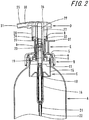
FIG. 2 is a side sectional view illustrating the state where a pump stopper is inserted to a dispenser during distribution according to Embodiment 1 of the present disclosure; -
FIG. 3 is a front half-sectional view illustrating the state where a pump stopper is inserted to a dispenser during use according to Embodiment 1 of the present disclosure; -
FIGs. 4A and 4B are each a perspective view illustrating a pump stopper according to Embodiment 1 of the present disclosure, withFIG. 4A illustrating the state where the pump stopper is used as a stopper, andFIG. 4B illustrating the state where the pump stopper is used as a finger-pressing member; -
FIGs. 5A and 5B are respectively an upper view and a front half-sectional view, each illustrating the state where a pump stopper is inserted to a dispenser during distribution according toEmbodiment 2 of the present disclosure; -
FIG. 6 is a front half-sectional view illustrating the state where a pump stopper is inserted to a dispenser during use according toEmbodiment 2 of the present disclosure; and -
FIGs. 7A and 7B are each a perspective view illustrating a pump stopper according toEmbodiment 2 of the present disclosure, withFIG. 7A illustrating the state where the pump stopper is used as a stopper, andFIG. 7B illustrating the state where the pump stopper is used as a finger-pressing member. - Preferred embodiments of the present disclosure are described below with reference to the drawings.
- In
FIGs. 1A, 1B , and2 , reference numeral A denotes a container main body containing a content liquid, reference numeral B denotes an attachment cap fitted to the container main body A, reference numeral C denotes a pump fitted to the attachment cap, reference numeral D denotes a nozzle head fitted to an upper end of the pump C, and reference numeral E denotes a pump stopper inserted detachably between the nozzle head D and the attachment cap B. - Additionally, in the following description, an upper direction as seen in
FIG. 1B is defined as "upward", and a lower direction as seen inFIG. 1B is defined as "downward". - A dispenser is formed by assembling the attachment cap B, the pump C, and the nozzle head D.
- The container main body A includes a mouth tubular portion 1 and a
trunk 2. The mouth tubular portion 1 is provided, on an outer circumference thereof, with a male screw 3 to which the attachment cap B is screwed. - The attachment cap B includes a
top wall 5, aguide tube 6 extending in a standing manner through a middle portion of thetop wall 5, and a side circumferential wall 7 extending vertically downward from an outer circumferential edge of thetop wall 5. - The
guide tube 6, on an inner circumference thereof, guides the nozzle head D being displaced upward and downward as described later, and theguide tube 6 is also provided, in an outer circumferential upper end thereof, with anengagement protruding ridge 8. - The side circumferential wall 7 is provided, in an inner circumferential upper end thereof, with an engagement portion 9 that engages with the pump C, and the side circumferential wall 7 is also provided, below the engagement portion 9, with a female screw 10 that is screwed to the male screw 3.
- As illustrated in
FIG. 2 , the pump C includes a large-diameter air cylinder 15, which is fitted via the engagement portion 9 to the inner circumferential upper end of the side circumferential wall 7 included in the attachment cap B, and a small-diameterliquid cylinder 16, which extends vertically below theair cylinder 15 coaxially. - Inside the
liquid cylinder 16 and theair cylinder 15, astem 19, which is urged upward with respect to the attachment cap B, is fitted in a manner such that thestep 19 is displaceable upward and downward. Thestem 19 has a tubular shape with open upper and lower ends, and aliquid piston 18 is fitted to a lower portion of thestem 19, and anair piston 17, which slides inside theair cylinder 15, is also coupled to an outer circumferential upper portion of thestem 19. - The
liquid cylinder 16 has a bottom portion from which apipe holding tube 21 extends integrally, and to thepipe holding tube 21, adrawing pipe 22 is connected. - Between the
stem 19 and a fittingtubular portion 20, there is defined an air-liquid mixing chamber 23, in which a liquid from theliquid cylinder 16 and air from theair cylinder 15 join. In thefitting tubular portion 20, which communicates with the air-liquid mixing chamber 23, two foamingmembers 24 are fitted. - In the present embodiment, a pair of ring bodies, with meshes having different coarseness being stretched, is fitted as the foaming
members 24. However, a single ring body, with a mesh being stretched, may be fitted, or three or more meshes may be fitted, and any of these may be selected as needed. - To an upper end of the
stem 19, thefitting tubular portion 20 is fitted, and moreover, a lower end of a fittingtubular body 27 included in the nozzle head D, which is described later, is fitted. - The inside of the pump C is configured in a known manner and not limited to a particular configuration, as long as the pump C may supply the content liquid and air and may allow the mixed liquid and air to be foamed through the foaming members and dispensed through the nozzle.
- As illustrated in
FIGs. 1A, 1B , and2 , the nozzle head D includes ahead portion 26 provided, on one side thereof, with anozzle 25, fittingtubular body 27 extending vertically below thehead portion 26, and atubular body 28. - Inside the fitting
tubular body 27, acirculation path 29 is defined in communication with thestem 19, and a dispensingpath 30, which communicates with thecirculation path 29 and extends to a front end of thenozzle 25, is also provided, with a front end thereof forming anozzle port 31. - To an inner circumference of a lower end of the
tubular body 28, anengagement member 32 is fitted, and a small gap is defined with respect to an outer circumference of the guide tube 6 (the engagement protruding ridge 8) included in the attachment cap B. - As illustrated in
FIGs. 4A and 4B , the pump stopper E includes a substantially cylindrical-shaped stoppermain body 35 that is provided with aside opening 38 in a manner such that the stoppermain body 35 is C-shaped in an upper view thereof and that is inserted to the outer circumference of theguide tube 6 included in the attachment cap B. The pump stopper E further includes two finger-pressingmembers 36, which extend radially outward from an outer circumferential lower end side of the stoppermain body 35, and atab portion 37 extending radially outward from an outer circumferential upper end side of the stoppermain body 35. - The
tab portion 37 is arranged on an opposite side to theside opening 38 of the stoppermain body 35, and the two finger-pressingmembers 36 are each arranged to foam an angle of approximately 90 degrees with respect to thetab portion 37. - Although in the present embodiment the two finger-pressing
members 36 are provided, the finger-pressing members may be omitted or, if provided, the shapes and the positions thereof may be suitably selected. - Furthermore, in the present embodiment, the
tab portion 37 has a flat-plate shape extending horizontally from the outer circumferential upper end side of the stoppermain body 35 and includes an anti-slipperyconvex portion 37a formed on an upper surface of thetab portion 37. However, the shape of thetab portion 37 may be suitably selected and may be, for example, an elongated flat-plate shape. - The stopper
main body 35 includes an innertubular wall 39, which is formed in a cylindrical shape a portion of which is cut away circumferentially alongside end surfaces 39a, an outertubular wall 40, which is connected to an outer circumferential side of the innertubular wall 39 with a predetermined distance therebetween and which is formed in a cylindrical shape a portion of which is cut away circumferentially along end surfaces 40a similarly to the innertubular wall 39, and flat plate-shaped connectingpieces 41, which connect anupper end side 39b of the innertubular wall 39 and anupper end side 40b of the outertubular wall 40 at three positions and which each has a fan shape in an upper view. - Between the inner
tubular wall 39 and the outertubular wall 40 and from the lower end side to the connectingpieces 41 on the upper end side, there is defined aspace portion 42, which permits thetubular body 28 of the nozzle head D to be displaced downward, and the three connectingpieces 41 serve as regulating portions that hinder the nozzle head D from being depressed. - Here, a description is given of modes of use and advantageous effects of the present embodiment.
- Firstly, when the pump stopper E is inserted to the
guide tube 6 included in the attachment cap B in manufacturing or the like of the dispenser in which the attachment cap B, the pump C, and the nozzle head D are assembled, as illustrated inFIGs. 1A, 1B , and4A , thetab portion 37 is held and pushed radially inward in the state where theside opening 38 of the stoppermain body 35 faces to theguide tube 6 so that the upper end side of the stoppermain body 35 that includes the three connectingpieces 41 as the regulating portions opposes to the lower end portion of thetubular body 28 included in the nozzle head D. - At this time, the side end surfaces 39a of the inner
tubular wall 39 of the stoppermain body 35 firstly abuts against an outer circumferential surface of theguide tube 6, and as the stoppermain body 35 is pushed radially inward in this state, the side end surfaces 39a of the innertubular wall 39 are stretched out due to elastic deformation, and, correspondingly, the outertubular wall 40, which is connected to the innertubular wall 39 by the connectingpieces 41, is inserted to theguide tube 6 while undergoing elastic deformation. - Thus, the pump stopper E is inserted to the
guide tube 6. - Additionally, although in the present embodiment the three connecting
pieces 41 are used to connect theupper end side 39b of the innertubular wall 39 and theupper end side 40b of the outertubular wall 40, the number of the connectingpieces 41 may be increased or reduced as needed, and even a single connecting piece may be used to connect the innertubular wall 39 and the outertubular wall 40 over the entire circumferences. - Preferably, a single connecting piece is used for connection, because, by doing so, the inner
tubular wall 39 and the outertubular wall 40 are more likely to be deformed, and this facilitates insertion of the pump stopper E to the dispenser, compared with cases where theupper end side 39b of the innertubular wall 39 and theupper end side 40b of the outertubular wall 40 are connected all over the circumferential direction. - Furthermore, in cases where the finger-pressing
members 36 of the pump stopper E are not required, the outertubular wall 40 may be omitted in the stoppermain body 35. In this case, only the innertubular wall 39, and the connectingpieces 41 and thetab portion 37, which extend radially outward from the outer circumferential upper end side of the innertubular wall 39, may be provided, and the configuration of the pump stopper E is simplified. - Thus, in the state where the pump stopper E is inserted to the
guide tube 6, the three connectingpieces 41, as the regulating portions provided on the upper end side of the stoppermain body 35, are close to or in abutment with a lower end edge of thetubular body 28 included in the nozzle head D, and the lower end side of the stoppermain body 35 is located above thetop wall 5 included in the attachment cap B. This hinders downward displacement of the nozzle head D. - Subsequently, when the pump stopper E is removed from the
guide tube 6 in use or the like of the dispenser, thetab portion 37 is pulled radially outward (in an arrow direction inFIG. 1A . Then, both circumferential end edges of the innertubular wall 39 included in the stoppermain body 35 are stretched out due to elastic deformation, and, correspondingly, the outertubular wall 40, which is connected to the innertubular wall 39 by the connectingpieces 41, undergoes elastic deformation. Thus, the pump stopper E is removed from theguide tube 6. - Subsequently, as illustrated in
FIG. 3 , after being removed from theguide tube 6, the pump stopper E is inverted upside-down and inserted to theguide tube 6 in a manner such that the three connectingpieces 41 are located above thetop wall 5 included in the attachment cap B. - This allows, when the nozzle head D is depressed, the lower end edge of the
tubular body 28 to be displaced downward in thespace portion 42 defined in the stoppermain body 35. - Furthermore, when the finger-pressing
members 36 are used, fingers may be pressed up against the finger-pressingmembers 36 for one-handed operation. - To dispense the content liquid in the form of foam, the nozzle head D is depressed. Then, the
stem 11, which is fitted to the fittingtubular body 27, is depressed and pressurizes the liquid contained in theliquid cylinder 16 and air contained in theair cylinder 15. Consequently, the liquid and air are supplied to the air-liquid mixing chamber 23 to be joined, foamed through the foamingmembers 24, and subsequently, pass through thecirculation path 29 and the dispensingpath 30 and are dispensed to the outside from thenozzle port 31 included in the nozzle head D. - Additionally, although in the present embodiment a so-called foamer pump that dispenses the liquid in the form of foam from the nozzle is illustrated as the dispenser, a pump that dispenses the liquid from the nozzle without foaming the liquid may be used instead of the foamer pump or, alternatively, a so-called aerosol dispenser may also be used.
- Next, a description is given of
Embodiment 2 in which the configuration of the finger-pressing member is changed. - Regarding the present embodiment, the same constituent portions as those in the first embodiment are denoted by the same reference numerals, and a detailed description thereof is omitted, and the description focuses on differences.
- In
FIGs. 5A and 5B , reference numeral A denotes the container main body containing a content medium, reference numeral B denotes the attachment cap fitted to the container main body A, reference numeral C denotes the pump fitted to the attachment cap, reference numeral D denotes the nozzle head fitted to an upper end of the pump C, and reference numeral F denotes a pump stopper detachably inserted between the nozzle head D and the attachment cap B. - As illustrated in
FIGs. 7A and 7B , the pump stopper F includes the stoppermain body 35, which is inserted to the outer circumference of theguide tube 6 included in the attachment cap B, and two finger-pressingmembers 43, which extend radially outward from the outer circumferential upper end side of the stoppermain body 35, and thetab portion 37. - The tab portion37 is arranged on the opposite side to the
side opening 35 of the stoppermain body 35, and the two finger-pressingmembers 43 are each arranged to foam an angle of approximately 90 degrees with respect to thetab portion 37. - Here, a description is given of modes of use and advantageous effects of the present embodiment.
- The pump stopper F according to the present embodiment differs from the pump stopper E according to the Embodiment 1 in that the positions of the finger-pressing
members 36 and the length of each finger-pressingmember 36 in the radial direction are changed. - That is to say, in the present embodiment, the finger-pressing
members 43 are arranged on the outer circumferential upper end side of the stoppermain body 35, and the finger-pressingmembers 43 extend further outward than an outer edge of the attachment cap B. - Accordingly, even when being used in a dispenser that is smaller than that in Embodiment 1, the pump stopper F according to the present embodiment allows, during use in which the pump stopper F is inverted upside-down, the finger-pressing
members 43 and thehead portion 26 to be positioned at an appropriate distance, by increasing the distance between the finger-pressingmembers 43 and thehead portion 26. - Furthermore, similarly to Embodiment 1, the configuration of the pump stopper F is simplified. That is to say, the outer
tubular wall 40 may be omitted in the stoppermain body 35, and only the innertubular wall 39, and the connectingpieces 41, the finger-pressingmembers 43, and thetab portion 37, which extend radially outward from the outer circumferential upper end side of the innertubular wall 39, may be provided. - In this case, unlike Embodiment 1, the finger-pressing
members 43 may be provided. - Other advantageous effects are substantially the same as those in Embodiment 1.
- A pump stopper according to the present disclosure is applicable to a dispenser including a foamer pump that dispenses a content liquid from a nozzle and other types of a dispenser, such as a dispenser that dispenses a content liquid directly in the form of liquid, a spray dispenser that sprays a content liquid in the form of atomized particles, and an aerosol dispenser. During distribution, the pump stopper serves as a normal pump stopper, and during use, the pump stopper is inverted upside-down and inserted to a dispenser. Accordingly, the pump stopper does not need to be stored separately, and if needed, may also be used as a finger-pressing member. Thus, the pump stopper may be widely used as a pump stopper in a pump dispenser, especially as a pump stopper for a container filled with a content medium, such as a cleanser and a cosmetic product, for which a nozzle head of the dispenser needs to be depressed during use.
-
- A
- Container main body
- B
- Attachment cap
- C
- Pump
- D
- Nozzle head
- E, F
- Pump stopper
- 1
- Mouth tubular portion
- 2
- Trunk
- 3
- Male screw
- 5
- Top wall
- 6
- Guide tube
- 7
- Side circumferential wall
- 8
- Engagement protruding ridge
- 9
- Engagement portion
- 10
- Female screw
- 15
- Air cylinder
- 16
- Liquid cylinder
- 17
- Air piston
- 18
- Liquid piston
- 19
- Stem
- 20
- Fitting tubular portion
- 21
- Pipe holding tube
- 22
- Drawing pipe
- 23
- Gas-liquid mixing chamber
- 24
- Foaming member
- 25
- Nozzle
- 26
- Head portion
- 27
- Fitting tubular body
- 28
- Tubular body
- 29
- Circulation path
- 30
- Dispensing path
- 31
- Nozzle port
- 32
- Engagement member
- 35
- Stopper main body
- 36, 43
- Finger-pressing member
- 37
- Tab portion
- 37a
- Anti-slippery convex portion
- 38
- Side opening
- 39
- Inner tubular wall
- 39a, 40a
- Side end surfaces
- 39b, 40b
- Upper end side
- 40
- Outer tubular wall
- 41
- Connecting piece (regulating portion)
- 42
- Space portion
Claims (5)
- A pump stopper configured to be inserted detachably to a dispenser including: an attachment cap that is fitted to a mouth tubular portion of a container main body and that has a top wall; a pump that is fitted to the attachment cap; and a nozzle head that is fitted to an upper end of the pump and that has a tubular body extending vertically downward, wherein
the pump stopper comprises a substantially cylindrical-shaped stopper main body provided with a side opening in a manner such that the stopper main body is C-shaped in an upper view thereof, and
the stopper main body includes, on one of an upper end side and a lower end side thereof, a regulating portion that prevents the tubular body of the nozzle head from being displaced downward, and, on another one of the upper end side and the lower end side thereof, a space portion that allows the tubular body of the nozzle head to be displaced downward when the pump stopper is inserted between the top wall of the attachment cap and the tubular body of the nozzle head. - The pump stopper according to claim 1, wherein the pump stopper further includes a finger-pressing member that extends radially outward from the stopper main body.
- The pump stopper according to claim 1 or 2, wherein the stopper main body further includes: an inner tubular wall, which is formed in a cylindrical shape a portion of which is cut away circumferentially along side end surfaces thereof; and an outer tubular wall, which is connected to an outer circumferential side of the inner tubular wall with a predetermined distance therebetween and which is formed in a cylindrical shape a portion of which is cut away circumferentially along side end surfaces thereof, and wherein the space portion is defined between the inner tubular wall and the outer tubular wall, and one of an upper end side and a lower end side of each of the inner tubular wall and the outer tubular wall is connected each other as the regulating portion.
- The pump stopper according to claim 3, wherein the regulating portion comprises at least one connecting piece that connects an end portion of the inner tubular wall and an end portion of the outer tubular wall.
- The pump stopper according to one of claims 1 to 4, wherein the stopper main body further includes a tab portion that extends radially outward on an opposite side to the side opening.
Applications Claiming Priority (2)
| Application Number | Priority Date | Filing Date | Title |
|---|---|---|---|
| JP2014113546A JP6278840B2 (en) | 2014-05-30 | 2014-05-30 | Pump stopper |
| PCT/JP2015/001828 WO2015182028A1 (en) | 2014-05-30 | 2015-03-30 | Pump stopper |
Publications (3)
| Publication Number | Publication Date |
|---|---|
| EP3150508A1 true EP3150508A1 (en) | 2017-04-05 |
| EP3150508A4 EP3150508A4 (en) | 2018-01-24 |
| EP3150508B1 EP3150508B1 (en) | 2020-03-11 |
Family
ID=54698390
Family Applications (1)
| Application Number | Title | Priority Date | Filing Date |
|---|---|---|---|
| EP15798771.0A Active EP3150508B1 (en) | 2014-05-30 | 2015-03-30 | Pump stopper |
Country Status (4)
| Country | Link |
|---|---|
| EP (1) | EP3150508B1 (en) |
| JP (1) | JP6278840B2 (en) |
| CN (1) | CN106414266B (en) |
| WO (1) | WO2015182028A1 (en) |
Families Citing this family (3)
| Publication number | Priority date | Publication date | Assignee | Title |
|---|---|---|---|---|
| JP7057223B2 (en) * | 2018-05-31 | 2022-04-19 | 株式会社吉野工業所 | Foam ejector with stopper |
| JP1640506S (en) * | 2019-02-25 | 2019-09-02 | ||
| USD913804S1 (en) * | 2019-05-06 | 2021-03-23 | Natura Cosméticos S.A. | Flask |
Family Cites Families (9)
| Publication number | Priority date | Publication date | Assignee | Title |
|---|---|---|---|---|
| JP2593100Y2 (en) * | 1992-10-12 | 1999-03-31 | 株式会社吉野工業所 | Liquid injection device |
| JP2003165591A (en) * | 2001-11-30 | 2003-06-10 | Yoshino Kogyosho Co Ltd | Container with pump |
| JP4526967B2 (en) * | 2005-01-31 | 2010-08-18 | 株式会社吉野工業所 | Container with dispenser |
| FR2907435B1 (en) * | 2006-10-20 | 2009-01-09 | Valois Sas | DEVICE FOR DISPENSING FLUID PRODUCT. |
| JP5064180B2 (en) * | 2007-11-15 | 2012-10-31 | ライオン株式会社 | Dispenser and container with dispenser |
| JP2009286486A (en) * | 2008-06-02 | 2009-12-10 | Mitani Valve Co Ltd | Stopper member for jetting container and jetting container |
| JP5253431B2 (en) * | 2010-02-15 | 2013-07-31 | 株式会社吉野工業所 | Container with dispenser |
| CN102145782B (en) * | 2011-04-28 | 2012-11-28 | 余姚晟祺塑业有限公司 | Pressing type emulsion spray nozzle |
| KR200471184Y1 (en) * | 2012-02-02 | 2014-02-11 | 주식회사 하나 | A Cosmetic Container Having Loosing Prevention Function |
-
2014
- 2014-05-30 JP JP2014113546A patent/JP6278840B2/en active Active
-
2015
- 2015-03-30 EP EP15798771.0A patent/EP3150508B1/en active Active
- 2015-03-30 WO PCT/JP2015/001828 patent/WO2015182028A1/en not_active Ceased
- 2015-03-30 CN CN201580026238.4A patent/CN106414266B/en active Active
Also Published As
| Publication number | Publication date |
|---|---|
| JP6278840B2 (en) | 2018-02-14 |
| WO2015182028A1 (en) | 2015-12-03 |
| EP3150508B1 (en) | 2020-03-11 |
| EP3150508A4 (en) | 2018-01-24 |
| CN106414266B (en) | 2018-06-12 |
| JP2015227198A (en) | 2015-12-17 |
| CN106414266A (en) | 2017-02-15 |
Similar Documents
| Publication | Publication Date | Title |
|---|---|---|
| US10737285B2 (en) | Dispenser system | |
| EP2105209B1 (en) | Apparatus for dispensing fluids using a press-fit dip tube | |
| RU2608490C2 (en) | Sprayer with built-in pressure channel | |
| US9987645B2 (en) | Concentrated cleaning capsule and atomizer for dispensing cleaning solution therefrom | |
| TW467851B (en) | Liquid container with extensible dispensing tube | |
| CN104736254B (en) | Reverse extruding foaming device | |
| CN108697221B (en) | Filling assembly for the manufacture of dual content packaging and dispensing devices | |
| US9010572B2 (en) | Tip seal having a position indicator, the tip seal being configured to dispense a foam solution | |
| US9744546B2 (en) | Sample dispenser with priming cradle | |
| WO2007126852A3 (en) | Drop dispenser for the delivery of uniform droplets of viscous liquids | |
| JP2011528585A (en) | Dispensing assembly with syringe holder and separately provided syringe | |
| EP3150508B1 (en) | Pump stopper | |
| US8950608B2 (en) | Universal adapter system for bottle containers using a dispensing pump or cap | |
| US20100224655A1 (en) | Assembly for packaging and dispensing a cosmetic product | |
| US20180214894A1 (en) | Droplet dispensing assembly and converter attachment for spray-to-droplet conversion | |
| US20170006997A1 (en) | Cosmetic dropper with clean design | |
| US20160052662A1 (en) | Application system for small dose liquid, gel, serum or cream | |
| BR112014032939B1 (en) | DISPENSER HEAD, DISPENSER DEVICE AND USE OF A DISPENSER HEAD | |
| US20170100733A1 (en) | Bottle kit | |
| JP6587550B2 (en) | Discharge container | |
| KR101474325B1 (en) | Dispensing Device for Comsmetics and Cosmetic Container Having the Same | |
| EP3774590B1 (en) | Dispenser adapter | |
| US8167220B2 (en) | Headpiece for actuator | |
| JP5554160B2 (en) | Dispenser with applicator | |
| JP2010260591A (en) | Two-part agent mixing container |
Legal Events
| Date | Code | Title | Description |
|---|---|---|---|
| STAA | Information on the status of an ep patent application or granted ep patent |
Free format text: STATUS: THE INTERNATIONAL PUBLICATION HAS BEEN MADE |
|
| PUAI | Public reference made under article 153(3) epc to a published international application that has entered the european phase |
Free format text: ORIGINAL CODE: 0009012 |
|
| STAA | Information on the status of an ep patent application or granted ep patent |
Free format text: STATUS: REQUEST FOR EXAMINATION WAS MADE |
|
| 17P | Request for examination filed |
Effective date: 20161031 |
|
| AK | Designated contracting states |
Kind code of ref document: A1 Designated state(s): AL AT BE BG CH CY CZ DE DK EE ES FI FR GB GR HR HU IE IS IT LI LT LU LV MC MK MT NL NO PL PT RO RS SE SI SK SM TR |
|
| AX | Request for extension of the european patent |
Extension state: BA ME |
|
| DAV | Request for validation of the european patent (deleted) | ||
| DAX | Request for extension of the european patent (deleted) | ||
| A4 | Supplementary search report drawn up and despatched |
Effective date: 20171222 |
|
| RIC1 | Information provided on ipc code assigned before grant |
Ipc: B05B 11/00 20060101ALI20171218BHEP Ipc: B65D 47/34 20060101AFI20171218BHEP |
|
| GRAP | Despatch of communication of intention to grant a patent |
Free format text: ORIGINAL CODE: EPIDOSNIGR1 |
|
| STAA | Information on the status of an ep patent application or granted ep patent |
Free format text: STATUS: GRANT OF PATENT IS INTENDED |
|
| INTG | Intention to grant announced |
Effective date: 20191206 |
|
| GRAS | Grant fee paid |
Free format text: ORIGINAL CODE: EPIDOSNIGR3 |
|
| GRAA | (expected) grant |
Free format text: ORIGINAL CODE: 0009210 |
|
| STAA | Information on the status of an ep patent application or granted ep patent |
Free format text: STATUS: THE PATENT HAS BEEN GRANTED |
|
| AK | Designated contracting states |
Kind code of ref document: B1 Designated state(s): AL AT BE BG CH CY CZ DE DK EE ES FI FR GB GR HR HU IE IS IT LI LT LU LV MC MK MT NL NO PL PT RO RS SE SI SK SM TR |
|
| REG | Reference to a national code |
Ref country code: GB Ref legal event code: FG4D |
|
| REG | Reference to a national code |
Ref country code: CH Ref legal event code: EP |
|
| REG | Reference to a national code |
Ref country code: AT Ref legal event code: REF Ref document number: 1242887 Country of ref document: AT Kind code of ref document: T Effective date: 20200315 |
|
| REG | Reference to a national code |
Ref country code: IE Ref legal event code: FG4D |
|
| REG | Reference to a national code |
Ref country code: DE Ref legal event code: R096 Ref document number: 602015048677 Country of ref document: DE |
|
| PG25 | Lapsed in a contracting state [announced via postgrant information from national office to epo] |
Ref country code: NO Free format text: LAPSE BECAUSE OF FAILURE TO SUBMIT A TRANSLATION OF THE DESCRIPTION OR TO PAY THE FEE WITHIN THE PRESCRIBED TIME-LIMIT Effective date: 20200611 Ref country code: RS Free format text: LAPSE BECAUSE OF FAILURE TO SUBMIT A TRANSLATION OF THE DESCRIPTION OR TO PAY THE FEE WITHIN THE PRESCRIBED TIME-LIMIT Effective date: 20200311 Ref country code: FI Free format text: LAPSE BECAUSE OF FAILURE TO SUBMIT A TRANSLATION OF THE DESCRIPTION OR TO PAY THE FEE WITHIN THE PRESCRIBED TIME-LIMIT Effective date: 20200311 |
|
| REG | Reference to a national code |
Ref country code: NL Ref legal event code: MP Effective date: 20200311 |
|
| PG25 | Lapsed in a contracting state [announced via postgrant information from national office to epo] |
Ref country code: BG Free format text: LAPSE BECAUSE OF FAILURE TO SUBMIT A TRANSLATION OF THE DESCRIPTION OR TO PAY THE FEE WITHIN THE PRESCRIBED TIME-LIMIT Effective date: 20200611 Ref country code: SE Free format text: LAPSE BECAUSE OF FAILURE TO SUBMIT A TRANSLATION OF THE DESCRIPTION OR TO PAY THE FEE WITHIN THE PRESCRIBED TIME-LIMIT Effective date: 20200311 Ref country code: LV Free format text: LAPSE BECAUSE OF FAILURE TO SUBMIT A TRANSLATION OF THE DESCRIPTION OR TO PAY THE FEE WITHIN THE PRESCRIBED TIME-LIMIT Effective date: 20200311 Ref country code: HR Free format text: LAPSE BECAUSE OF FAILURE TO SUBMIT A TRANSLATION OF THE DESCRIPTION OR TO PAY THE FEE WITHIN THE PRESCRIBED TIME-LIMIT Effective date: 20200311 Ref country code: GR Free format text: LAPSE BECAUSE OF FAILURE TO SUBMIT A TRANSLATION OF THE DESCRIPTION OR TO PAY THE FEE WITHIN THE PRESCRIBED TIME-LIMIT Effective date: 20200612 |
|
| REG | Reference to a national code |
Ref country code: LT Ref legal event code: MG4D |
|
| PG25 | Lapsed in a contracting state [announced via postgrant information from national office to epo] |
Ref country code: NL Free format text: LAPSE BECAUSE OF FAILURE TO SUBMIT A TRANSLATION OF THE DESCRIPTION OR TO PAY THE FEE WITHIN THE PRESCRIBED TIME-LIMIT Effective date: 20200311 |
|
| PG25 | Lapsed in a contracting state [announced via postgrant information from national office to epo] |
Ref country code: EE Free format text: LAPSE BECAUSE OF FAILURE TO SUBMIT A TRANSLATION OF THE DESCRIPTION OR TO PAY THE FEE WITHIN THE PRESCRIBED TIME-LIMIT Effective date: 20200311 Ref country code: SM Free format text: LAPSE BECAUSE OF FAILURE TO SUBMIT A TRANSLATION OF THE DESCRIPTION OR TO PAY THE FEE WITHIN THE PRESCRIBED TIME-LIMIT Effective date: 20200311 Ref country code: SK Free format text: LAPSE BECAUSE OF FAILURE TO SUBMIT A TRANSLATION OF THE DESCRIPTION OR TO PAY THE FEE WITHIN THE PRESCRIBED TIME-LIMIT Effective date: 20200311 Ref country code: CZ Free format text: LAPSE BECAUSE OF FAILURE TO SUBMIT A TRANSLATION OF THE DESCRIPTION OR TO PAY THE FEE WITHIN THE PRESCRIBED TIME-LIMIT Effective date: 20200311 Ref country code: RO Free format text: LAPSE BECAUSE OF FAILURE TO SUBMIT A TRANSLATION OF THE DESCRIPTION OR TO PAY THE FEE WITHIN THE PRESCRIBED TIME-LIMIT Effective date: 20200311 Ref country code: IS Free format text: LAPSE BECAUSE OF FAILURE TO SUBMIT A TRANSLATION OF THE DESCRIPTION OR TO PAY THE FEE WITHIN THE PRESCRIBED TIME-LIMIT Effective date: 20200711 Ref country code: PT Free format text: LAPSE BECAUSE OF FAILURE TO SUBMIT A TRANSLATION OF THE DESCRIPTION OR TO PAY THE FEE WITHIN THE PRESCRIBED TIME-LIMIT Effective date: 20200805 Ref country code: LT Free format text: LAPSE BECAUSE OF FAILURE TO SUBMIT A TRANSLATION OF THE DESCRIPTION OR TO PAY THE FEE WITHIN THE PRESCRIBED TIME-LIMIT Effective date: 20200311 |
|
| REG | Reference to a national code |
Ref country code: CH Ref legal event code: PL |
|
| REG | Reference to a national code |
Ref country code: AT Ref legal event code: MK05 Ref document number: 1242887 Country of ref document: AT Kind code of ref document: T Effective date: 20200311 |
|
| REG | Reference to a national code |
Ref country code: DE Ref legal event code: R097 Ref document number: 602015048677 Country of ref document: DE |
|
| REG | Reference to a national code |
Ref country code: BE Ref legal event code: MM Effective date: 20200331 |
|
| PG25 | Lapsed in a contracting state [announced via postgrant information from national office to epo] |
Ref country code: LU Free format text: LAPSE BECAUSE OF NON-PAYMENT OF DUE FEES Effective date: 20200330 Ref country code: MC Free format text: LAPSE BECAUSE OF FAILURE TO SUBMIT A TRANSLATION OF THE DESCRIPTION OR TO PAY THE FEE WITHIN THE PRESCRIBED TIME-LIMIT Effective date: 20200311 |
|
| PLBE | No opposition filed within time limit |
Free format text: ORIGINAL CODE: 0009261 |
|
| STAA | Information on the status of an ep patent application or granted ep patent |
Free format text: STATUS: NO OPPOSITION FILED WITHIN TIME LIMIT |
|
| PG25 | Lapsed in a contracting state [announced via postgrant information from national office to epo] |
Ref country code: LI Free format text: LAPSE BECAUSE OF NON-PAYMENT OF DUE FEES Effective date: 20200331 Ref country code: IT Free format text: LAPSE BECAUSE OF FAILURE TO SUBMIT A TRANSLATION OF THE DESCRIPTION OR TO PAY THE FEE WITHIN THE PRESCRIBED TIME-LIMIT Effective date: 20200311 Ref country code: DK Free format text: LAPSE BECAUSE OF FAILURE TO SUBMIT A TRANSLATION OF THE DESCRIPTION OR TO PAY THE FEE WITHIN THE PRESCRIBED TIME-LIMIT Effective date: 20200311 Ref country code: AT Free format text: LAPSE BECAUSE OF FAILURE TO SUBMIT A TRANSLATION OF THE DESCRIPTION OR TO PAY THE FEE WITHIN THE PRESCRIBED TIME-LIMIT Effective date: 20200311 Ref country code: IE Free format text: LAPSE BECAUSE OF NON-PAYMENT OF DUE FEES Effective date: 20200330 Ref country code: ES Free format text: LAPSE BECAUSE OF FAILURE TO SUBMIT A TRANSLATION OF THE DESCRIPTION OR TO PAY THE FEE WITHIN THE PRESCRIBED TIME-LIMIT Effective date: 20200311 Ref country code: CH Free format text: LAPSE BECAUSE OF NON-PAYMENT OF DUE FEES Effective date: 20200331 |
|
| 26N | No opposition filed |
Effective date: 20201214 |
|
| PG25 | Lapsed in a contracting state [announced via postgrant information from national office to epo] |
Ref country code: SI Free format text: LAPSE BECAUSE OF FAILURE TO SUBMIT A TRANSLATION OF THE DESCRIPTION OR TO PAY THE FEE WITHIN THE PRESCRIBED TIME-LIMIT Effective date: 20200311 Ref country code: PL Free format text: LAPSE BECAUSE OF FAILURE TO SUBMIT A TRANSLATION OF THE DESCRIPTION OR TO PAY THE FEE WITHIN THE PRESCRIBED TIME-LIMIT Effective date: 20200311 Ref country code: BE Free format text: LAPSE BECAUSE OF NON-PAYMENT OF DUE FEES Effective date: 20200331 |
|
| PG25 | Lapsed in a contracting state [announced via postgrant information from national office to epo] |
Ref country code: TR Free format text: LAPSE BECAUSE OF FAILURE TO SUBMIT A TRANSLATION OF THE DESCRIPTION OR TO PAY THE FEE WITHIN THE PRESCRIBED TIME-LIMIT Effective date: 20200311 Ref country code: MT Free format text: LAPSE BECAUSE OF FAILURE TO SUBMIT A TRANSLATION OF THE DESCRIPTION OR TO PAY THE FEE WITHIN THE PRESCRIBED TIME-LIMIT Effective date: 20200311 Ref country code: CY Free format text: LAPSE BECAUSE OF FAILURE TO SUBMIT A TRANSLATION OF THE DESCRIPTION OR TO PAY THE FEE WITHIN THE PRESCRIBED TIME-LIMIT Effective date: 20200311 |
|
| PG25 | Lapsed in a contracting state [announced via postgrant information from national office to epo] |
Ref country code: MK Free format text: LAPSE BECAUSE OF FAILURE TO SUBMIT A TRANSLATION OF THE DESCRIPTION OR TO PAY THE FEE WITHIN THE PRESCRIBED TIME-LIMIT Effective date: 20200311 Ref country code: AL Free format text: LAPSE BECAUSE OF FAILURE TO SUBMIT A TRANSLATION OF THE DESCRIPTION OR TO PAY THE FEE WITHIN THE PRESCRIBED TIME-LIMIT Effective date: 20200311 |
|
| PGFP | Annual fee paid to national office [announced via postgrant information from national office to epo] |
Ref country code: GB Payment date: 20250206 Year of fee payment: 11 |
|
| PGFP | Annual fee paid to national office [announced via postgrant information from national office to epo] |
Ref country code: DE Payment date: 20260204 Year of fee payment: 12 |
|
| PGFP | Annual fee paid to national office [announced via postgrant information from national office to epo] |
Ref country code: FR Payment date: 20260209 Year of fee payment: 12 |