EP3150415A1 - Hybrid vehicle driving device - Google Patents
Hybrid vehicle driving device Download PDFInfo
- Publication number
- EP3150415A1 EP3150415A1 EP16189073.6A EP16189073A EP3150415A1 EP 3150415 A1 EP3150415 A1 EP 3150415A1 EP 16189073 A EP16189073 A EP 16189073A EP 3150415 A1 EP3150415 A1 EP 3150415A1
- Authority
- EP
- European Patent Office
- Prior art keywords
- rotational speed
- engine
- motor generator
- connection
- input shaft
- Prior art date
- Legal status (The legal status is an assumption and is not a legal conclusion. Google has not performed a legal analysis and makes no representation as to the accuracy of the status listed.)
- Withdrawn
Links
Images


Classifications
-
- B—PERFORMING OPERATIONS; TRANSPORTING
- B60—VEHICLES IN GENERAL
- B60W—CONJOINT CONTROL OF VEHICLE SUB-UNITS OF DIFFERENT TYPE OR DIFFERENT FUNCTION; CONTROL SYSTEMS SPECIALLY ADAPTED FOR HYBRID VEHICLES; ROAD VEHICLE DRIVE CONTROL SYSTEMS FOR PURPOSES NOT RELATED TO THE CONTROL OF A PARTICULAR SUB-UNIT
- B60W10/00—Conjoint control of vehicle sub-units of different type or different function
- B60W10/04—Conjoint control of vehicle sub-units of different type or different function including control of propulsion units
- B60W10/06—Conjoint control of vehicle sub-units of different type or different function including control of propulsion units including control of combustion engines
-
- B—PERFORMING OPERATIONS; TRANSPORTING
- B60—VEHICLES IN GENERAL
- B60K—ARRANGEMENT OR MOUNTING OF PROPULSION UNITS OR OF TRANSMISSIONS IN VEHICLES; ARRANGEMENT OR MOUNTING OF PLURAL DIVERSE PRIME-MOVERS IN VEHICLES; AUXILIARY DRIVES FOR VEHICLES; INSTRUMENTATION OR DASHBOARDS FOR VEHICLES; ARRANGEMENTS IN CONNECTION WITH COOLING, AIR INTAKE, GAS EXHAUST OR FUEL SUPPLY OF PROPULSION UNITS IN VEHICLES
- B60K6/00—Arrangement or mounting of plural diverse prime-movers for mutual or common propulsion, e.g. hybrid propulsion systems comprising electric motors and internal combustion engines
- B60K6/20—Arrangement or mounting of plural diverse prime-movers for mutual or common propulsion, e.g. hybrid propulsion systems comprising electric motors and internal combustion engines the prime-movers consisting of electric motors and internal combustion engines, e.g. HEVs
- B60K6/22—Arrangement or mounting of plural diverse prime-movers for mutual or common propulsion, e.g. hybrid propulsion systems comprising electric motors and internal combustion engines the prime-movers consisting of electric motors and internal combustion engines, e.g. HEVs characterised by apparatus, components or means specially adapted for HEVs
- B60K6/38—Arrangement or mounting of plural diverse prime-movers for mutual or common propulsion, e.g. hybrid propulsion systems comprising electric motors and internal combustion engines the prime-movers consisting of electric motors and internal combustion engines, e.g. HEVs characterised by apparatus, components or means specially adapted for HEVs characterised by the driveline clutches
- B60K6/387—Actuated clutches, i.e. clutches engaged or disengaged by electric, hydraulic or mechanical actuating means
-
- B—PERFORMING OPERATIONS; TRANSPORTING
- B60—VEHICLES IN GENERAL
- B60W—CONJOINT CONTROL OF VEHICLE SUB-UNITS OF DIFFERENT TYPE OR DIFFERENT FUNCTION; CONTROL SYSTEMS SPECIALLY ADAPTED FOR HYBRID VEHICLES; ROAD VEHICLE DRIVE CONTROL SYSTEMS FOR PURPOSES NOT RELATED TO THE CONTROL OF A PARTICULAR SUB-UNIT
- B60W20/00—Control systems specially adapted for hybrid vehicles
- B60W20/20—Control strategies involving selection of hybrid configuration, e.g. selection between series or parallel configuration
-
- B—PERFORMING OPERATIONS; TRANSPORTING
- B60—VEHICLES IN GENERAL
- B60K—ARRANGEMENT OR MOUNTING OF PROPULSION UNITS OR OF TRANSMISSIONS IN VEHICLES; ARRANGEMENT OR MOUNTING OF PLURAL DIVERSE PRIME-MOVERS IN VEHICLES; AUXILIARY DRIVES FOR VEHICLES; INSTRUMENTATION OR DASHBOARDS FOR VEHICLES; ARRANGEMENTS IN CONNECTION WITH COOLING, AIR INTAKE, GAS EXHAUST OR FUEL SUPPLY OF PROPULSION UNITS IN VEHICLES
- B60K6/00—Arrangement or mounting of plural diverse prime-movers for mutual or common propulsion, e.g. hybrid propulsion systems comprising electric motors and internal combustion engines
- B60K6/20—Arrangement or mounting of plural diverse prime-movers for mutual or common propulsion, e.g. hybrid propulsion systems comprising electric motors and internal combustion engines the prime-movers consisting of electric motors and internal combustion engines, e.g. HEVs
- B60K6/22—Arrangement or mounting of plural diverse prime-movers for mutual or common propulsion, e.g. hybrid propulsion systems comprising electric motors and internal combustion engines the prime-movers consisting of electric motors and internal combustion engines, e.g. HEVs characterised by apparatus, components or means specially adapted for HEVs
- B60K6/36—Arrangement or mounting of plural diverse prime-movers for mutual or common propulsion, e.g. hybrid propulsion systems comprising electric motors and internal combustion engines the prime-movers consisting of electric motors and internal combustion engines, e.g. HEVs characterised by apparatus, components or means specially adapted for HEVs characterised by the transmission gearings
-
- B—PERFORMING OPERATIONS; TRANSPORTING
- B60—VEHICLES IN GENERAL
- B60K—ARRANGEMENT OR MOUNTING OF PROPULSION UNITS OR OF TRANSMISSIONS IN VEHICLES; ARRANGEMENT OR MOUNTING OF PLURAL DIVERSE PRIME-MOVERS IN VEHICLES; AUXILIARY DRIVES FOR VEHICLES; INSTRUMENTATION OR DASHBOARDS FOR VEHICLES; ARRANGEMENTS IN CONNECTION WITH COOLING, AIR INTAKE, GAS EXHAUST OR FUEL SUPPLY OF PROPULSION UNITS IN VEHICLES
- B60K6/00—Arrangement or mounting of plural diverse prime-movers for mutual or common propulsion, e.g. hybrid propulsion systems comprising electric motors and internal combustion engines
- B60K6/20—Arrangement or mounting of plural diverse prime-movers for mutual or common propulsion, e.g. hybrid propulsion systems comprising electric motors and internal combustion engines the prime-movers consisting of electric motors and internal combustion engines, e.g. HEVs
- B60K6/22—Arrangement or mounting of plural diverse prime-movers for mutual or common propulsion, e.g. hybrid propulsion systems comprising electric motors and internal combustion engines the prime-movers consisting of electric motors and internal combustion engines, e.g. HEVs characterised by apparatus, components or means specially adapted for HEVs
- B60K6/38—Arrangement or mounting of plural diverse prime-movers for mutual or common propulsion, e.g. hybrid propulsion systems comprising electric motors and internal combustion engines the prime-movers consisting of electric motors and internal combustion engines, e.g. HEVs characterised by apparatus, components or means specially adapted for HEVs characterised by the driveline clutches
- B60K6/383—One-way clutches or freewheel devices
-
- B—PERFORMING OPERATIONS; TRANSPORTING
- B60—VEHICLES IN GENERAL
- B60K—ARRANGEMENT OR MOUNTING OF PROPULSION UNITS OR OF TRANSMISSIONS IN VEHICLES; ARRANGEMENT OR MOUNTING OF PLURAL DIVERSE PRIME-MOVERS IN VEHICLES; AUXILIARY DRIVES FOR VEHICLES; INSTRUMENTATION OR DASHBOARDS FOR VEHICLES; ARRANGEMENTS IN CONNECTION WITH COOLING, AIR INTAKE, GAS EXHAUST OR FUEL SUPPLY OF PROPULSION UNITS IN VEHICLES
- B60K6/00—Arrangement or mounting of plural diverse prime-movers for mutual or common propulsion, e.g. hybrid propulsion systems comprising electric motors and internal combustion engines
- B60K6/20—Arrangement or mounting of plural diverse prime-movers for mutual or common propulsion, e.g. hybrid propulsion systems comprising electric motors and internal combustion engines the prime-movers consisting of electric motors and internal combustion engines, e.g. HEVs
- B60K6/42—Arrangement or mounting of plural diverse prime-movers for mutual or common propulsion, e.g. hybrid propulsion systems comprising electric motors and internal combustion engines the prime-movers consisting of electric motors and internal combustion engines, e.g. HEVs characterised by the architecture of the hybrid electric vehicle
- B60K6/44—Series-parallel type
- B60K6/442—Series-parallel switching type
-
- B—PERFORMING OPERATIONS; TRANSPORTING
- B60—VEHICLES IN GENERAL
- B60W—CONJOINT CONTROL OF VEHICLE SUB-UNITS OF DIFFERENT TYPE OR DIFFERENT FUNCTION; CONTROL SYSTEMS SPECIALLY ADAPTED FOR HYBRID VEHICLES; ROAD VEHICLE DRIVE CONTROL SYSTEMS FOR PURPOSES NOT RELATED TO THE CONTROL OF A PARTICULAR SUB-UNIT
- B60W20/00—Control systems specially adapted for hybrid vehicles
-
- B—PERFORMING OPERATIONS; TRANSPORTING
- B60—VEHICLES IN GENERAL
- B60W—CONJOINT CONTROL OF VEHICLE SUB-UNITS OF DIFFERENT TYPE OR DIFFERENT FUNCTION; CONTROL SYSTEMS SPECIALLY ADAPTED FOR HYBRID VEHICLES; ROAD VEHICLE DRIVE CONTROL SYSTEMS FOR PURPOSES NOT RELATED TO THE CONTROL OF A PARTICULAR SUB-UNIT
- B60W20/00—Control systems specially adapted for hybrid vehicles
- B60W20/40—Controlling the engagement or disengagement of prime movers, e.g. for transition between prime movers
-
- B—PERFORMING OPERATIONS; TRANSPORTING
- B60—VEHICLES IN GENERAL
- B60K—ARRANGEMENT OR MOUNTING OF PROPULSION UNITS OR OF TRANSMISSIONS IN VEHICLES; ARRANGEMENT OR MOUNTING OF PLURAL DIVERSE PRIME-MOVERS IN VEHICLES; AUXILIARY DRIVES FOR VEHICLES; INSTRUMENTATION OR DASHBOARDS FOR VEHICLES; ARRANGEMENTS IN CONNECTION WITH COOLING, AIR INTAKE, GAS EXHAUST OR FUEL SUPPLY OF PROPULSION UNITS IN VEHICLES
- B60K6/00—Arrangement or mounting of plural diverse prime-movers for mutual or common propulsion, e.g. hybrid propulsion systems comprising electric motors and internal combustion engines
- B60K6/20—Arrangement or mounting of plural diverse prime-movers for mutual or common propulsion, e.g. hybrid propulsion systems comprising electric motors and internal combustion engines the prime-movers consisting of electric motors and internal combustion engines, e.g. HEVs
- B60K6/22—Arrangement or mounting of plural diverse prime-movers for mutual or common propulsion, e.g. hybrid propulsion systems comprising electric motors and internal combustion engines the prime-movers consisting of electric motors and internal combustion engines, e.g. HEVs characterised by apparatus, components or means specially adapted for HEVs
- B60K6/26—Arrangement or mounting of plural diverse prime-movers for mutual or common propulsion, e.g. hybrid propulsion systems comprising electric motors and internal combustion engines the prime-movers consisting of electric motors and internal combustion engines, e.g. HEVs characterised by apparatus, components or means specially adapted for HEVs characterised by the motors or the generators
- B60K2006/266—Arrangement or mounting of plural diverse prime-movers for mutual or common propulsion, e.g. hybrid propulsion systems comprising electric motors and internal combustion engines the prime-movers consisting of electric motors and internal combustion engines, e.g. HEVs characterised by apparatus, components or means specially adapted for HEVs characterised by the motors or the generators with two coaxial motors or generators
-
- B—PERFORMING OPERATIONS; TRANSPORTING
- B60—VEHICLES IN GENERAL
- B60K—ARRANGEMENT OR MOUNTING OF PROPULSION UNITS OR OF TRANSMISSIONS IN VEHICLES; ARRANGEMENT OR MOUNTING OF PLURAL DIVERSE PRIME-MOVERS IN VEHICLES; AUXILIARY DRIVES FOR VEHICLES; INSTRUMENTATION OR DASHBOARDS FOR VEHICLES; ARRANGEMENTS IN CONNECTION WITH COOLING, AIR INTAKE, GAS EXHAUST OR FUEL SUPPLY OF PROPULSION UNITS IN VEHICLES
- B60K6/00—Arrangement or mounting of plural diverse prime-movers for mutual or common propulsion, e.g. hybrid propulsion systems comprising electric motors and internal combustion engines
- B60K6/20—Arrangement or mounting of plural diverse prime-movers for mutual or common propulsion, e.g. hybrid propulsion systems comprising electric motors and internal combustion engines the prime-movers consisting of electric motors and internal combustion engines, e.g. HEVs
- B60K6/22—Arrangement or mounting of plural diverse prime-movers for mutual or common propulsion, e.g. hybrid propulsion systems comprising electric motors and internal combustion engines the prime-movers consisting of electric motors and internal combustion engines, e.g. HEVs characterised by apparatus, components or means specially adapted for HEVs
- B60K6/26—Arrangement or mounting of plural diverse prime-movers for mutual or common propulsion, e.g. hybrid propulsion systems comprising electric motors and internal combustion engines the prime-movers consisting of electric motors and internal combustion engines, e.g. HEVs characterised by apparatus, components or means specially adapted for HEVs characterised by the motors or the generators
- B60K2006/268—Electric drive motor starts the engine, i.e. used as starter motor
-
- B—PERFORMING OPERATIONS; TRANSPORTING
- B60—VEHICLES IN GENERAL
- B60K—ARRANGEMENT OR MOUNTING OF PROPULSION UNITS OR OF TRANSMISSIONS IN VEHICLES; ARRANGEMENT OR MOUNTING OF PLURAL DIVERSE PRIME-MOVERS IN VEHICLES; AUXILIARY DRIVES FOR VEHICLES; INSTRUMENTATION OR DASHBOARDS FOR VEHICLES; ARRANGEMENTS IN CONNECTION WITH COOLING, AIR INTAKE, GAS EXHAUST OR FUEL SUPPLY OF PROPULSION UNITS IN VEHICLES
- B60K6/00—Arrangement or mounting of plural diverse prime-movers for mutual or common propulsion, e.g. hybrid propulsion systems comprising electric motors and internal combustion engines
- B60K6/20—Arrangement or mounting of plural diverse prime-movers for mutual or common propulsion, e.g. hybrid propulsion systems comprising electric motors and internal combustion engines the prime-movers consisting of electric motors and internal combustion engines, e.g. HEVs
- B60K6/22—Arrangement or mounting of plural diverse prime-movers for mutual or common propulsion, e.g. hybrid propulsion systems comprising electric motors and internal combustion engines the prime-movers consisting of electric motors and internal combustion engines, e.g. HEVs characterised by apparatus, components or means specially adapted for HEVs
- B60K6/26—Arrangement or mounting of plural diverse prime-movers for mutual or common propulsion, e.g. hybrid propulsion systems comprising electric motors and internal combustion engines the prime-movers consisting of electric motors and internal combustion engines, e.g. HEVs characterised by apparatus, components or means specially adapted for HEVs characterised by the motors or the generators
-
- B—PERFORMING OPERATIONS; TRANSPORTING
- B60—VEHICLES IN GENERAL
- B60W—CONJOINT CONTROL OF VEHICLE SUB-UNITS OF DIFFERENT TYPE OR DIFFERENT FUNCTION; CONTROL SYSTEMS SPECIALLY ADAPTED FOR HYBRID VEHICLES; ROAD VEHICLE DRIVE CONTROL SYSTEMS FOR PURPOSES NOT RELATED TO THE CONTROL OF A PARTICULAR SUB-UNIT
- B60W10/00—Conjoint control of vehicle sub-units of different type or different function
- B60W10/02—Conjoint control of vehicle sub-units of different type or different function including control of driveline clutches
-
- B—PERFORMING OPERATIONS; TRANSPORTING
- B60—VEHICLES IN GENERAL
- B60W—CONJOINT CONTROL OF VEHICLE SUB-UNITS OF DIFFERENT TYPE OR DIFFERENT FUNCTION; CONTROL SYSTEMS SPECIALLY ADAPTED FOR HYBRID VEHICLES; ROAD VEHICLE DRIVE CONTROL SYSTEMS FOR PURPOSES NOT RELATED TO THE CONTROL OF A PARTICULAR SUB-UNIT
- B60W10/00—Conjoint control of vehicle sub-units of different type or different function
- B60W10/04—Conjoint control of vehicle sub-units of different type or different function including control of propulsion units
- B60W10/08—Conjoint control of vehicle sub-units of different type or different function including control of propulsion units including control of electric propulsion units, e.g. motors or generators
-
- B—PERFORMING OPERATIONS; TRANSPORTING
- B60—VEHICLES IN GENERAL
- B60W—CONJOINT CONTROL OF VEHICLE SUB-UNITS OF DIFFERENT TYPE OR DIFFERENT FUNCTION; CONTROL SYSTEMS SPECIALLY ADAPTED FOR HYBRID VEHICLES; ROAD VEHICLE DRIVE CONTROL SYSTEMS FOR PURPOSES NOT RELATED TO THE CONTROL OF A PARTICULAR SUB-UNIT
- B60W2510/00—Input parameters relating to a particular sub-units
- B60W2510/02—Clutches
- B60W2510/0241—Clutch slip, i.e. difference between input and output speeds
-
- B—PERFORMING OPERATIONS; TRANSPORTING
- B60—VEHICLES IN GENERAL
- B60W—CONJOINT CONTROL OF VEHICLE SUB-UNITS OF DIFFERENT TYPE OR DIFFERENT FUNCTION; CONTROL SYSTEMS SPECIALLY ADAPTED FOR HYBRID VEHICLES; ROAD VEHICLE DRIVE CONTROL SYSTEMS FOR PURPOSES NOT RELATED TO THE CONTROL OF A PARTICULAR SUB-UNIT
- B60W2710/00—Output or target parameters relating to a particular sub-units
- B60W2710/02—Clutches
- B60W2710/021—Clutch engagement state
-
- B—PERFORMING OPERATIONS; TRANSPORTING
- B60—VEHICLES IN GENERAL
- B60W—CONJOINT CONTROL OF VEHICLE SUB-UNITS OF DIFFERENT TYPE OR DIFFERENT FUNCTION; CONTROL SYSTEMS SPECIALLY ADAPTED FOR HYBRID VEHICLES; ROAD VEHICLE DRIVE CONTROL SYSTEMS FOR PURPOSES NOT RELATED TO THE CONTROL OF A PARTICULAR SUB-UNIT
- B60W2710/00—Output or target parameters relating to a particular sub-units
- B60W2710/06—Combustion engines, Gas turbines
- B60W2710/0644—Engine speed
-
- B—PERFORMING OPERATIONS; TRANSPORTING
- B60—VEHICLES IN GENERAL
- B60W—CONJOINT CONTROL OF VEHICLE SUB-UNITS OF DIFFERENT TYPE OR DIFFERENT FUNCTION; CONTROL SYSTEMS SPECIALLY ADAPTED FOR HYBRID VEHICLES; ROAD VEHICLE DRIVE CONTROL SYSTEMS FOR PURPOSES NOT RELATED TO THE CONTROL OF A PARTICULAR SUB-UNIT
- B60W2710/00—Output or target parameters relating to a particular sub-units
- B60W2710/08—Electric propulsion units
- B60W2710/081—Speed
-
- B—PERFORMING OPERATIONS; TRANSPORTING
- B60—VEHICLES IN GENERAL
- B60W—CONJOINT CONTROL OF VEHICLE SUB-UNITS OF DIFFERENT TYPE OR DIFFERENT FUNCTION; CONTROL SYSTEMS SPECIALLY ADAPTED FOR HYBRID VEHICLES; ROAD VEHICLE DRIVE CONTROL SYSTEMS FOR PURPOSES NOT RELATED TO THE CONTROL OF A PARTICULAR SUB-UNIT
- B60W2710/00—Output or target parameters relating to a particular sub-units
- B60W2710/10—Change speed gearings
- B60W2710/1011—Input shaft speed, e.g. turbine speed
-
- B—PERFORMING OPERATIONS; TRANSPORTING
- B60—VEHICLES IN GENERAL
- B60Y—INDEXING SCHEME RELATING TO ASPECTS CROSS-CUTTING VEHICLE TECHNOLOGY
- B60Y2200/00—Type of vehicle
- B60Y2200/90—Vehicles comprising electric prime movers
- B60Y2200/92—Hybrid vehicles
-
- B—PERFORMING OPERATIONS; TRANSPORTING
- B60—VEHICLES IN GENERAL
- B60Y—INDEXING SCHEME RELATING TO ASPECTS CROSS-CUTTING VEHICLE TECHNOLOGY
- B60Y2300/00—Purposes or special features of road vehicle drive control systems
- B60Y2300/18—Propelling the vehicle
- B60Y2300/19—Improvement of gear change, e.g. synchronisation or smoothing gear shift
-
- B—PERFORMING OPERATIONS; TRANSPORTING
- B60—VEHICLES IN GENERAL
- B60Y—INDEXING SCHEME RELATING TO ASPECTS CROSS-CUTTING VEHICLE TECHNOLOGY
- B60Y2400/00—Special features of vehicle units
- B60Y2400/42—Clutches or brakes
- B60Y2400/427—One-way clutches
-
- Y—GENERAL TAGGING OF NEW TECHNOLOGICAL DEVELOPMENTS; GENERAL TAGGING OF CROSS-SECTIONAL TECHNOLOGIES SPANNING OVER SEVERAL SECTIONS OF THE IPC; TECHNICAL SUBJECTS COVERED BY FORMER USPC CROSS-REFERENCE ART COLLECTIONS [XRACs] AND DIGESTS
- Y02—TECHNOLOGIES OR APPLICATIONS FOR MITIGATION OR ADAPTATION AGAINST CLIMATE CHANGE
- Y02T—CLIMATE CHANGE MITIGATION TECHNOLOGIES RELATED TO TRANSPORTATION
- Y02T10/00—Road transport of goods or passengers
- Y02T10/60—Other road transportation technologies with climate change mitigation effect
- Y02T10/62—Hybrid vehicles
-
- Y—GENERAL TAGGING OF NEW TECHNOLOGICAL DEVELOPMENTS; GENERAL TAGGING OF CROSS-SECTIONAL TECHNOLOGIES SPANNING OVER SEVERAL SECTIONS OF THE IPC; TECHNICAL SUBJECTS COVERED BY FORMER USPC CROSS-REFERENCE ART COLLECTIONS [XRACs] AND DIGESTS
- Y10—TECHNICAL SUBJECTS COVERED BY FORMER USPC
- Y10S—TECHNICAL SUBJECTS COVERED BY FORMER USPC CROSS-REFERENCE ART COLLECTIONS [XRACs] AND DIGESTS
- Y10S903/00—Hybrid electric vehicles, HEVS
- Y10S903/902—Prime movers comprising electrical and internal combustion motors
- Y10S903/903—Prime movers comprising electrical and internal combustion motors having energy storing means, e.g. battery, capacitor
- Y10S903/904—Component specially adapted for hev
- Y10S903/912—Drive line clutch
- Y10S903/913—One way
-
- Y—GENERAL TAGGING OF NEW TECHNOLOGICAL DEVELOPMENTS; GENERAL TAGGING OF CROSS-SECTIONAL TECHNOLOGIES SPANNING OVER SEVERAL SECTIONS OF THE IPC; TECHNICAL SUBJECTS COVERED BY FORMER USPC CROSS-REFERENCE ART COLLECTIONS [XRACs] AND DIGESTS
- Y10—TECHNICAL SUBJECTS COVERED BY FORMER USPC
- Y10S—TECHNICAL SUBJECTS COVERED BY FORMER USPC CROSS-REFERENCE ART COLLECTIONS [XRACs] AND DIGESTS
- Y10S903/00—Hybrid electric vehicles, HEVS
- Y10S903/902—Prime movers comprising electrical and internal combustion motors
- Y10S903/903—Prime movers comprising electrical and internal combustion motors having energy storing means, e.g. battery, capacitor
- Y10S903/93—Conjoint control of different elements
Definitions
- This disclosure relates to a hybrid vehicle driving device.
- the hybrid vehicle driving device includes a first clutch for connecting and disconnecting the engine and an output shaft to and from each other, and a second clutch for connecting and disconnecting the first motor generator and the output shaft to and from each other.
- a hybrid vehicle driving device includes: a first motor generator; a second motor generator; an input shaft to which an engine is rotatably linked; an output shaft to which a driving wheel and the second motor generator are rotatably linked; a rotating member which is rotatably linked to the output shaft; a connection member to which the first motor generator is connected; a connection mechanism which connects and disconnects the connection member and the rotating member to and from each other; a one-way clutch which connects the input shaft and the connection member to each other in a case where the rotational speed of the input shaft is higher than the rotational speed of the connection member, and disconnects the input shaft and the connection member from each other in a case where the rotational speed of the input shaft is lower than the rotational speed of the connection member; a synchronization control portion which synchronizes the rotational speed of the first motor generator with the rotational speed of the rotating member in the middle of executing the engine connection control that connects the engine to the rotating member by the one-way clutch after connecting the connection member
- connection member and the rotating member are connected to each other, and the first motor generator is connected to the rotating member. Accordingly, when the first motor generator is connected to the rotating member, the inertial force of the engine is not input to the connection mechanism or the rotating member. Therefore, an excessive force does not act on a member on the driving wheel rather than the connection mechanism and the rotating member which configure the hybrid vehicle driving device, and an excessive force does not act on a member, such as a gear that changes the speed of the hybrid vehicle driving device.
- the engine is controlled by the second engine control portion so that the rotational speed of the input shaft is synchronized with the rotational speed of the connection member.
- the input shaft and the connection member are connected to each other by the one-way clutch, the engine is connected to the rotating member via the one-way clutch and the connection member, and the engine is connected to the output shaft. In other words, in a state where there is no difference in rotational speed between the input shaft and the connection member, the input shaft and the connection member are connected to each other via the one-way clutch.
- the hybrid vehicle driving device may be configured to further include: a driving force assist portion which drives the driving wheel by the second motor generator in the middle of executing the engine connection control.
- the hybrid vehicle driving device may be configured such that the one-way clutch is placed in a locked state in a case where the rotational speed of the input shaft linked to a driving shaft of the engine is higher than the rotational speed of a rotor of the first motor generator, the input shaft and the tubular connection member are connected to each other, and the driving shaft is rotatably linked to the rotor.
- the hybrid vehicle driving device may be configured such that the one-way clutch is placed in a free state in a case where the rotational speed of the input shaft is lower than the rotational speed of the tubular connection member, and the input shaft and the connection member are disconnected from each other.
- the hybrid vehicle driving device may be configured such that the rotating member is provided to be turnable around a shaft line of the tubular connection member.
- the vehicle V includes the hybrid vehicle driving device 1, a differential 19, drive shafts 20L and 20R, driving wheels 21 L and 21 R, an accelerator pedal 51, and an accelerator sensor 52.
- the hybrid vehicle driving device 1 includes an engine 2, a fly wheel 3, an automatic transmission 4, a first motor generator 11, a second motor generator 12, an inverter device 16, a battery 17, a control portion 18, an engine rotational speed sensor 171, a first motor rotational speed sensor 172, and an output shaft rotational speed sensor 173.
- the engine 2 uses hydrocarbon-based fuel, such as gasoline or diesel, and is a gasoline engine or a diesel engine which outputs the engine torque Teng to a driving shaft 2a.
- the fly wheel 3 is linked to the driving shaft 2a.
- a damper 3a which absorbs the change in the input engine torque Teng, is provided.
- a configuration of the automatic transmission 4 will be described in detail later.
- the motor generators 11 and 12 are configured of rotors 11 a and 12a, and stators 11 b and 12b.
- the rotors 11 a and 12a are provided to be rotatable on the inner circumferential side of the stators 11b and 12b.
- the battery 17 is a secondary cell that accumulates the electric power, and supplies electric power to the stators 11b and 12b of the motor generators 11 and 12 via the inverter device 16.
- the inverter device 16 Based on a command from the control portion 18, the inverter device 16 increases voltage of the electric power supplied from the battery 17, supplies the electric power to the stators 11b and 12b of the motor generators 11 and 12, and drives the motor generators 11 and 12. In addition, based on the command from the control portion 18, the inverter device 16 decreases the voltage of the electric power generated in the motor generators 11 and 12, and charges the electric power to the battery 17. In a case where a brake pedal (not illustrated) is stepped, the control portion 18 outputs the command to the inverter device 16, generates the electric power in at least one of the first motor generator 11 and the second motor generator 12, and generates a regenerative braking force.
- the differential 19 transmits the torque output from the automatic transmission 4 to the left and right driving wheels 21L and 21 R via the left and right drive shafts 20L and 20R, and absorbs the difference in the rotational speed of the left and right driving wheels 21 L and 21 R.
- the accelerator pedal 51 is provided to be oscillatable in a driver's seat of the vehicle V.
- the accelerator sensor 52 detects an accelerator stroke Sta which is an operation amount of the accelerator pedal 51, and outputs the detection result to the control portion 18.
- the control portion 18 calculates the necessary torque Trd of a driver based on the accelerator stroke Sta detected by the accelerator sensor 52.
- the automatic transmission 4 includes a first input shaft 111, a second input shaft 112, a tubular member 115, a first output shaft 121, a second output shaft 122, a first drive gear 131, a second drive gear 132, a first driven gear 141, a second driven gear 142, an overdrive driven gear 149, a first output gear 151, a second output gear 152, a one-way clutch 161, a first connection mechanism 191, a second connection mechanism 192, and a third connection mechanism 193.
- the first input shaft 111 is provided coaxially to the driving shaft 2a and in series with the driving shaft 2a.
- the first input shaft 111 is rotatably linked to the driving shaft 2a of the engine 2 via the fly wheel 3.
- the tubular member 115 (connection member) has a cylinder shape, and is provided on the outer circumferential side of the first input shaft 111 and coaxially to the first input shaft 111.
- the second input shaft 112 is provided coaxially to the first input shaft 111 and in series with the first input shaft 111.
- the first output shaft 121 and the second output shaft 122 are provided in parallel to the first input shaft 111 and the second input shaft 112 in the radial direction.
- the rotor 11 a of the first motor generator 11 is rotatably linked to the tubular member 115. According to the configuration, the rotor 11 a is provided to be rotatable around the shaft line of the tubular member 115.
- the one-way clutch 161 is provided between the first input shaft 111 and the tubular member 115.
- the one-way clutch 161 is placed in a locked state, the first input shaft 111 and the tubular member 115 (connection member) are connected to each other, and the driving shaft 2a of the engine 2 is rotatably linked to the rotor 11 a of the first motor generator 11.
- the one-way clutch 161 is placed in a free state, and the first input shaft 111 and the tubular member 115 are disconnected from each other.
- the first drive gear 131 (rotating member) is provided to be turnable (rotatable) around the shaft line of the tubular member 115.
- the second drive gear 132 and the rotor 12a of the second motor generator 12 are fixed to the second input shaft 112.
- the first output gear 151 is fixed to the first output shaft 121, and meshes with a ring gear 19a of the differential 19.
- the first output shaft 121 is rotatably linked to the driving wheels 21L and 21 R.
- the first driven gear 141 is provided to be turnable around the first output shaft 121, and meshes with the second drive gear 132.
- the second motor generator 12 is rotatably linked to the first output shaft 121.
- the overdrive driven gear 149 is fixed to the second output shaft 122, and meshes with the first drive gear 131. According to the configuration, the first drive gear 131 (rotating member) is rotatably linked to the second output shaft 122.
- the second output gear 152 is fixed to the second output shaft 122, and meshes with the ring gear 19a of the differential 19. According to the configuration, the second output shaft 122 is rotatably linked to the driving wheels 21 L and 21 R.
- the gear diameter (pitch circle diameter, reference circle diameter) of the second output gear 152 becomes greater than the gear diameter of the first output gear 151.
- the second driven gear 142 is provided to be turnable around the second output shaft 122, and meshes with the second drive gear 132. According to the configuration, as will be described later, when the second driven gear 142 is connected to the second output shaft 122, the second motor generator 12 is rotatably linked to the second output shaft 122. The gear diameter of the second driven gear 142 becomes smaller than the gear diameter of the first driven gear 141.
- the first connection mechanism 191 is a dog clutch which is converted to any of a first shift position SP1 which connects the first drive gear 131 to the tubular member 115, a second shift position SP2 which connects the first input shaft 111 to the tubular member 115, and a first neutral N1 in which one of the first drive gear 131 and the first input shaft 111 is not connected to the tubular member 115.
- the first connection mechanism 191 connects and disconnects the first drive gear 131 or the first input shaft 111 and the tubular member 115 to and from each other.
- the first connection mechanism 191 is configured of a first hub 191 a, a first engaging member 191 b, a second engaging member 191c, a first sleeve 191d, and a first actuator 191e.
- the first hub 191a is fixed to the tubular member 115.
- the first engaging member 191b is provided to be fixed to the first drive gear 131 and to be adjacent to the first hub 191 a.
- the second engaging member 191 c is provided to be fixed to the first input shaft 111 and to be adjacent to the first hub 191 a.
- the first sleeve 191 d is spline-fitted to the first hub 191 a, is selectively engaged with one of the first engaging member 191 b and the second engaging member 191c, and is not engaged with both of the first engaging member 191b and the second engaging member 191 c.
- the first actuator 191e moves the first sleeve 191d to any of the first neutral N1, the first shift position SP1, and the second shift position SP2.
- the first hub 191 a is not engaged with one of the first engaging member 191b and the second engaging member 191c, and the rotor 11 a (tubular member 115) of the first motor generator 11 and the first input shaft 111 are disconnected from the first drive gear 131.
- the first hub 191 a is engaged with the first engaging member 191 b, the first drive gear 131 is connected to the tubular member 115, and the rotor 11 a of the first motor generator 11 is connected to the first drive gear 131.
- the first hub 191 a is engaged with the second engaging member 191c, and the first input shaft 111 is connected to the tubular member 115.
- the second connection mechanism 192 is a dog clutch which is converted to one of a third shift position SP3 in which the first driven gear 141 is connected to the first output shaft 121, and a second neutral N2 in which the first driven gear 141 is disconnected from the first output shaft 121.
- the second connection mechanism 192 connects and disconnects the first driven gear 141 and the first output shaft 121 to and from each other.
- the second connection mechanism 192 is configured of a second hub 192a, a third engaging member 192b, a second sleeve 192d, and a second actuator 192e.
- the second hub 192a is fixed to the first output shaft 121.
- the third engaging member 192b is fixed to the first driven gear 141.
- Structures and functions of the second hub 192a, the third engaging member 192b, the second sleeve 192d, and the second actuator 192e, are respectively similar to the structures and the functions of the first hub 191 a, the first engaging member 191 b, the first sleeve 191 d, and the first actuator 191e.
- the third connection mechanism 193 is a dog clutch which is converted to one of a fourth shift position SP4 in which the second driven gear 142 is connected to the second output shaft 122, and a third neutral N3 in which the second driven gear 142 is disconnected from the second output shaft 122.
- the third connection mechanism 193 connects and disconnects the second driven gear 142 and the second output shaft 122 to and from each other.
- the third connection mechanism 193 is configured of a third hub 193a, a fourth engaging member 193b, a third sleeve 193d, and a third actuator 193e.
- the third hub 193a is fixed to the second output shaft 122.
- the fourth engaging member 193b is fixed to the second driven gear 142.
- Structures and functions of the third hub 193a, the fourth engaging member 193b, the third sleeve 193d, and the third actuator 193e are respectively similar to the structures and the functions of the first hub 191a, the first engaging member 191b, the first sleeve 191d, and the first actuator 191e.
- the engine rotational speed sensor 171 detects the rotational speed of the driving shaft 2a, that is, the rotational speed (engine rotational speed Neng) of the engine 2.
- the first motor rotational speed sensor 172 detects the rotational speed (first motor rotational speed Nmg1) of the first motor generator 11.
- the output shaft rotational speed sensor 173 detects the rotational speed (output shaft rotational speed N0) of the second output shaft 122.
- the output shaft rotational speed sensor 173 may detect the rotational speed of the first output shaft 121.
- the sensors 171 to 173 output the detected signals to the control portion 18.
- the control portion 18 calculates the rotational speed (first drive gear rotational speed Ng1) of the first drive gear 131 based on the rotational speed of the first output shaft 121 detected by the output shaft rotational speed sensor 173.
- An EV-L mode is a mode in which the vehicle V travels only by a driving force of the second motor generator 12.
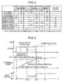
- the control portion 18 outputs the command to the connection mechanisms 191 to 193 so that the shift position becomes the field of the EV-L mode of the engagement table of Fig. 2 .
- the first driven gear 141 is connected to the first output shaft 121, and the second motor generator 12 is rotatably linked to the driving wheels 21 L and 21 R. Then, the second motor torque Tmg2 which is output from the second motor generator 12 is transmitted to the driving wheels 21 L and 21 R via the first output shaft 121.
- An EV-H mode is a mode in which the vehicle V travels only by the driving force of the second motor generator 12.
- a reduction gear ratio between the second motor generator 12 and the driving wheels 21 L and 21 R is smaller than the reduction gear ratio of the EV-L mode.
- the control portion 18 outputs the command to the connection mechanisms 191 to 193 so that the shift position becomes a field of the EV-H mode of the engagement table of Fig. 2 .
- the second driven gear 142 is connected to the second output shaft 122, and the second motor generator 12 is rotatably linked to the driving wheels 21 L and 21 R. Then, the second motor torque Tmg2 output from the second motor generator 12 is transmitted to the driving wheels 21 L and 21 R via the second output shaft 122.
- An EV-OD mode is a mode in which the vehicle V travels by the driving force of the first motor generator 11.
- the reduction gear ratio between the first motor generator 11 and the driving wheels 21 L and 21 R is smaller than the reduction gear ratio between the second motor generator 12 and the driving wheels 21 L and 21 R in the EV-H mode.
- the control portion 18 outputs the command to the connection mechanisms 191 to 193 so that the shift position becomes a field of the EV-OD mode of the engagement table of Fig. 2 .
- the first drive gear 131 is connected to the tubular member 115, and the first motor generator 11 is rotatably linked to the driving wheels 21 L and 21 R. Then, the first motor torque Tmg1 output from the first motor generator 11 is transmitted to the driving wheels 21 L and 21 R via the second output shaft 122.
- the EV-OD mode is achieved while changing the speed between the EV-L mode and the EV-H mode, the first motor torque Tmg1 is output to the driving wheels 21 L and 21 R from the first motor generator 11, and accordingly, the deceleration of the vehicle V is prevented.
- An engine travel mode is a mode in which the vehicle V travels by the driving force of the engine 2.
- the control portion 18 outputs the command to the connection mechanisms 191 to 193 so that the shift position becomes a field of the engine travel mode of the engagement table of Fig. 2 .
- the first drive gear 131 is connected to the tubular member 115.
- the one-way clutch 161 is placed in a locked state, the first input shaft 111 and the tubular member 115 are connected to each other, and the engine torque Teng is transmitted to the driving wheels 21 L and 21 R via the second output shaft 122.
- the first motor generator 11 is driven by the driving force of the engine 2, and the first motor generator 11 generates and supplies the electric power to auxiliary equipment of the vehicle V.
- the vehicle V travels by the driving force of both of the engine 2 and the first motor generator 11.
- a series L mode is a mode in which the first motor generator 11 is driven by the engine 2, the first motor generator 11 generates the electric power, and the vehicle V travels by the driving force of the second motor generator 12.
- the control portion 18 (series forming portion) outputs the command to the connection mechanisms 191 to 193 so that the shift position becomes a field of the series L mode of the engagement table of Fig. 2 .
- the first driven gear 141 is connected to the first output shaft 121, and the second motor generator 12 is rotatably linked to the driving wheels 21 L and 21 R.
- the one-way clutch 161 is locked, the first motor generator 11 is driven by the engine 2, and the electric power is generated in the first motor generator 11.
- the electric power generated in the first motor generator 11 is used in driving the second motor generator 12, and the second motor torque Tmg2 output from the second motor generator 12 is transmitted to the driving wheels 21 L and 21 R via the first output shaft 121.
- a series H mode is a mode in which the first motor generator 11 is driven by the driving force of the engine 2, the first motor generator 11 generates the electric power, and the vehicle V travels by the driving force of the second motor generator 12.
- the reduction gear ratio between the second motor generator 12 and the driving wheels 21 L and 21 R is smaller than the reduction gear ratio of the series L mode.
- the control portion 18 (series forming portion) outputs the command to the connection mechanisms 191 to 193 so that the shift position becomes a field of the series H mode of the engagement table of Fig. 2 .
- the second driven gear 142 is connected to the second output shaft 122, and the second motor generator 12 is rotatably linked to the driving wheels 21L and 21 R. Since the engine 2 is driven and the first input shaft 111 rotates, the one-way clutch 161 is locked, the first motor generator 11 is driven by the engine 2, and the electric power is generated in the first motor generator 11. The electric power generated in the first motor generator 11 is used in driving the second motor generator 12, and the second motor torque Tmg2 output from the second motor generator 12 is transmitted to the driving wheels 21 L and 21 R via the second output shaft 122.
- a parallel L mode is a mode in which the vehicle V travels by the driving force of the engine 2 and the second motor generator 12.
- the control portion 18 parallel forming portion
- the control portion 18 outputs the command to the connection mechanisms 191 to 193 so that the shift position becomes a field of the parallel L mode of the engagement table of Fig. 2 .
- the first drive gear 131 is connected to the tubular member 115, and the first motor generator 11 is rotatably linked to the driving wheels 21 L and 21 R.
- the first driven gear 141 is connected to the first output shaft 121.
- the one-way clutch 161 is locked, and the engine torque Teng output from the engine 2 is transmitted to the first motor generator 11 and the driving wheels 21 L and 21 R.
- the electric power generated in the first motor generator 11 is used in driving the second motor generator 12.
- the second motor torque Tmg2 output from the second motor generator 12 is transmitted to the driving wheels 21 L and 21 R via the first output shaft 121.
- the first motor generator 11 operates as an electric motor, and the first motor torque Tmg1 output from the first motor generator 11 is transmitted to the driving wheels 21 L and 21 R via the second output shaft 122.
- a parallel H mode is a mode in which the vehicle V travels by the driving force of the engine 2 and the second motor generator 12.
- the reduction gear ratio between the second motor generator 12 and the driving wheels 21 L and 21 R is smaller than the reduction gear ratio of the parallel L mode.
- the control portion 18 parallel forming portion
- the control portion 18 outputs the command to the connection mechanisms 191 to 193 so that the shift position becomes a field of the parallel H mode of the engagement table of Fig. 2 .
- the first drive gear 131 is connected to the tubular member 115, and the first motor generator 11 is rotatably linked to the driving wheels 21 L and 21 R.
- the second driven gear 142 is connected to the second output shaft 122. Since the engine 2 is driven and the first input shaft 111 rotates, the one-way clutch 161 is locked, and the engine torque Teng output from the engine 2 is transmitted to the first motor generator 11 and the driving wheels 21L and 21 R. The electric power generated in the first motor generator 11 is used in driving the second motor generator 12, and the second motor torque Tmg2 output from the second motor generator 12 is transmitted to the driving wheels 21L and 21 R via the second output shaft 122.
- the first motor generator 11 operates as an electric motor, and the first motor torque Tmg1 output from the first motor generator 11 is transmitted to the driving wheels 21 L and 21 R via the second output shaft 122.
- An engine start mode is a mode in which the engine 2 is started by the first motor generator 11.
- the control portion 18 outputs the command to the connection mechanisms 191 to 193 so that the shift position becomes a field of the engine start mode of the engagement table of Fig. 2 .
- the control portion 18 allows the first connection mechanism 191 to be in the second shift position SP2.
- the control portion 18 allows the second connection mechanism 192 and the third connection mechanism 193 to be in a shift position which corresponds to a traveling state of the vehicle V.
- the engine 2 is not started, when the "engine connection control" is started, the first input shaft 111 and the tubular member 115 are connected to each other by the first connection mechanism 191, and the rotor 11a of the first motor generator 11 and the driving shaft 2a of the engine 2 are connected to each other (T1 of Fig. 3 ). In addition, the engine 2 is started by the first motor generator 11 (T2 of Fig. 3 ).
- the first motor generator 11 is controlled so that the first motor rotational speed Nmg1 is synchronized with the first drive gear rotational speed Ng1 (T3 to T4 of Fig. 3 ).
- the engine rotational speed Neng is maintained to be the rotational speed lower than the first motor rotational speed Nmg1 (T3 to T4 of Fig. 3 ).
- the first drive gear 131 is connected to the tubular member 115, and the rotor 11 a of the first motor generator 11 is connected to the first drive gear 131 (T4 of Fig. 3 ).
- the engine 2 is controlled so that the engine rotational speed Neng is synchronized with the first drive gear rotational speed Ng1 (T5 to T6 of Fig. 3 ).
- the one-way clutch 161 is locked, the first input shaft 111 and the tubular member 115 are connected to each other, the driving shaft 2a of the engine 2 is connected to the first drive gear 131, and the driving shaft 2a of the engine 2 is connected to the second output shaft 122.
- the engine torque Teng is transmitted to the driving wheels 21 L and 21 R via the second output shaft 122.
- step S11 in a case where it is determined that the connection of the engine 2 to the second output shaft 122 is necessary (step S11: YES), the control portion 18 allows the program to proceed to step S12. Meanwhile, in a case where it is determined that the connection of the engine 2 to the second output shaft 122 is not necessary (step S11: NO), the control portion 18 allows the program to repeat the processing of step S11. In addition, in a case where it is determined that it is necessary to change the mode from any of the EV-L mode, the EV-H mode, the series L mode, and the series H mode, to any of the engine travel mode, the parallel L mode, and the parallel H mode, the control portion 18 determines that the connection of the engine 2 to the second output shaft 122 is necessary.
- step S12 the control portion 18 (driving force assist portion) outputs the command to the inverter device 16 so that the torque output by the hybrid vehicle driving device 1 becomes the required torque Trd, by the second motor torque Tmg2 output by the second motor generator 12. Accordingly, the driving wheels 21 L and 21 R are driven (assisted) by the second motor torque Tmg2 output by the second motor generator 12.
- step S21 in a case where it is determined that the mode of the hybrid vehicle driving device 1 is the EV-L mode or the EV-H mode and the engine 2 is stopped (step S21: YES), the control portion 18 allows the program to proceed to step S31. Meanwhile, in a case where it is determined that the mode of the hybrid vehicle driving device 1 is the series L mode or the series H mode and the engine 2 is not stopped (step S21: NO), the control portion 18 allows the program to proceed to step S41.
- step S31 the control portion 18 outputs the command to the first connection mechanism 191, connects the tubular member 115 and the first input shaft 111 to each other, and connects the rotor 11 a of the first motor generator 11 and the driving shaft 2a of the engine 2 to each other.
- step S32 the control portion 18 outputs the command to the inverter device 16 and the engine 2, and rotates the driving shaft 2a of the engine 2 by the first motor generator 11, and the engine 2 is started.
- step S33 in a case where it is determined that the start of the engine 2 is completed based on the detection result from the engine rotational speed sensor 171 (step S33: YES), the control portion 18 allows the program to proceed to step S34. Meanwhile, in a case where it is determined that the start of the engine 2 is not completed (step S33: NO), the control portion 18 allows the program to return to step S32.
- step S34 the control portion 18 outputs the command to the first connection mechanism 191, disconnects the tubular member 115 and the first input shaft 111 from each other, and disconnects the rotor 11 a of the first motor generator 11 and the driving shaft 2a of the engine 2 from each other (T3 of Fig. 3 ).
- step S41 the control portion 18 (synchronization control portion) outputs the command to the inverter device 16 and controls the first motor generator 11 so that the first motor rotational speed Nmg1 is synchronized with the first drive gear rotational speed Ng1 based on the detection result from the output shaft rotational speed sensor 173 and the first motor rotational speed sensor 172 (T3 to T4 of Fig. 3 ).
- step S42 the control portion 18 (first engine control portion) outputs the command to the engine 2 based on the detection result from the engine rotational speed sensor 171 and the first motor rotational speed sensor 172, and controls the engine 2 so that the engine rotational speed Neng becomes lower than the first motor rotational speed Nmg1 (T3 to T4 of Fig. 3 ). Accordingly, the one-way clutch 161 is placed in a free state.
- step S43 in a case where it is determined that the first motor rotational speed Nmg1 is synchronized with the first drive gear rotational speed Ng1 (step S43: YES), based on the detection result from the output shaft rotational speed sensor 173 and the first motor rotational speed sensor 172, the control portion 18 allows the program to proceed to step S44. Meanwhile, in a case where it is determined that the first motor rotational speed Nmg1 is not synchronized with the first drive gear rotational speed Ng1 (step S43: NO), the control portion 18 allows the program to return to step S41.
- step S44 the control portion 18 (connection portion) outputs the command to the first connection mechanism 191, connects the tubular member 115 and the first drive gear 131 to each other, and connects the rotor 11 a of the first motor generator 11 and the first drive gear 131 to each other (T4 of Fig. 3 ).
- the control portion 18 outputs the command to the inverter device 16, and stops the driving of the first motor generator 11.
- step S51 the control portion 18 (second engine control portion) controls the engine 2 (T5 to T6 of Fig. 3 ) so that the engine rotational speed Neng is synchronized with the first drive gear rotational speed Ng1, that is, so that the rotational speed of the first input shaft 111 is synchronized with the rotational speed of the tubular member 115 (connection member), based on the detection result from the engine rotational speed sensor 171 and the output shaft rotational speed sensor 173.
- step S52 in a case where it is determined that the engine rotational speed Neng is synchronized with the first drive gear rotational speed Ng1 (step S52: YES, T6 of Fig. 3 ) based on the detection result from the engine rotational speed sensor 171 and the output shaft rotational speed sensor 173, the control portion 18 allows the program to proceed to step S61. Meanwhile, in a case where it is determined that the engine rotational speed Neng is not synchronized with the first drive gear rotational speed Ng1 (step S52: NO), the control portion 18 allows the program to return to step S51.
- step S61 the control portion 18 changes the mode to any of the above-described engine travel mode, the parallel L mode, and the parallel H mode so that the torque output by the hybrid vehicle driving device 1 becomes the required torque Trd, and controls the engine 2, the first motor generator 11, and the second motor generator 12.
- the driving (assist) of the driving wheels 21 L and 21 R is stopped by the second motor torque Tmg2 output from the second motor generator 12.
- step S61 the control portion 18 allows the program to return to step S11.
- the inertial force of the engine 2 is not input to the first connection mechanism 191 or the first drive gear 131 (rotating member). Therefore, an excessive force does not act on the first hub 191 a, the first engaging member 191 b, and the first sleeve 191 d which configure the first connection mechanism 191, or the member on the driving wheels 21 L and 21 R rather than the first drive gear 131 (rotating member), and an excessive force does not act on the member, such as the gear which changes the speed of the hybrid vehicle driving device 1.
- the engine 2 is controlled by the control portion 18 (second engine control portion) so that the rotational speed of the first input shaft 111 is synchronized with the rotational speed of the tubular member 115 (connection member).
- the control portion 18 second engine control portion
- the rotational speed of the first input shaft 111 is synchronized with the rotational speed of the tubular member 115 (connection member) (T6 of Fig. 3 )
- the one-way clutch 161 the first input shaft 111 and the tubular member 115 (connection member) are connected to each other, and the driving shaft 2a of the engine 2 is connected to the first drive gear 131 (rotating member) via the one-way clutch 161, the tubular member 115 (rotating member), and the first connection mechanism 191, and is connected to the second output shaft 122.
- the first motor generator 11 since the first motor generator 11 has excellent responsiveness, during a short period of time, the first motor rotational speed Nmg1 is synchronized with the first drive gear rotational speed Ng1, and it is possible to connect the rotor 11 a of the first motor generator 11 to the first drive gear 131 by the first connection mechanism 191.
- the rotor 11 a of the first motor generator 11 is connected to the first drive gear 131, as the engine 2 is controlled so that the rotational speed of the first input shaft 111 is synchronized with the rotational speed of the tubular member 115 (connection member), the one-way clutch 161 is locked, and the driving shaft 2a of the engine 2 is connected to the second output shaft 122.
- connection and disconnection of the clutch compared to a configuration in which the driving shaft 2a of the engine 2 is connected to the second output shaft 122, during a short period of time, the engine 2 is connected to the second output shaft 122.
- the engine 2 is connected to the second output shaft 122.
- the control portion 18 drives the driving wheels 21 L and 21 R by the second motor generator 12 (T1 to T6 of Fig. 3 ). Therefore, in executing the "engine connection control", the deceleration of the vehicle V is suppressed, and the driver does not feel discomfort.
- the one-way clutch 161 may be placed in a locked state in a case where the rotational speed of the first input shaft 111 linked to the driving shaft 2a of the engine 2 is higher than the rotational speed of the rotor 11 a of the first motor generator 11, the first input shaft 111 and the tubular member 115 may be connected to each other, and the first driving shaft 2a may be rotatably linked to the rotor 12a.
- the one-way clutch 161 is placed in a free state in a case where the rotational speed of the first input shaft 111 is lower than the rotational speed of the tubular member 115, and the first input shaft 111 and the tubular member 115 may be disconnected from each other.
- first drive gear 131 may be provided to be turnable around a shaft line of the tubular member 115.
- the first connection mechanism 191 to the third connection mechanism 193 are dog clutches.
- the first connection mechanism 191 to the third connection mechanism 193 may be a synchronizer mechanism.
- the second connection mechanism 192 and the third connection mechanism 193 can be operated by the same actuator.
- the control portion 18 calculates the first drive gear rotational speed Ng1 based on the output shaft rotational speed No detected by the output shaft rotational speed sensor 173.
- the first drive gear rotational speed Ng1 is obtained by a sensor that detects the rotational speed of the first drive gear 131, may be employed.
- the control portion 18 calculates the first drive gear rotational speed Ng1, may be employed.
Landscapes
- Engineering & Computer Science (AREA)
- Transportation (AREA)
- Mechanical Engineering (AREA)
- Chemical & Material Sciences (AREA)
- Combustion & Propulsion (AREA)
- Automation & Control Theory (AREA)
- Electric Propulsion And Braking For Vehicles (AREA)
- Hybrid Electric Vehicles (AREA)
- Control Of Vehicle Engines Or Engines For Specific Uses (AREA)
Abstract
Description
- This disclosure relates to a hybrid vehicle driving device.
- From the related art, as described in
JP 2012-176730A - In the hybrid vehicle driving device described in
Reference 1, when the engine torque output by the engine is transmitted to the output shaft, the first clutch which is in a disconnected state is connected. At this time, there is a difference in the rotational speed between members connected by the first clutch, the power is transmitted by the connection of the first clutch, an inertial force of the engine is input to a member, such as a gear that changes the speed of the hybrid vehicle driving device via the first clutch, an excessive force acts on the member, and thus, it is necessary to take certain countermeasures against this. - Thus, a need exists for a hybrid vehicle driving device including a motor generator and an engine, in which an excessive force does not act on a member, such as a gear that changes the speed of the hybrid vehicle driving device when the engine is connected to the output shaft.
- A hybrid vehicle driving device according to an aspect of this disclosure includes: a first motor generator; a second motor generator; an input shaft to which an engine is rotatably linked; an output shaft to which a driving wheel and the second motor generator are rotatably linked; a rotating member which is rotatably linked to the output shaft; a connection member to which the first motor generator is connected; a connection mechanism which connects and disconnects the connection member and the rotating member to and from each other; a one-way clutch which connects the input shaft and the connection member to each other in a case where the rotational speed of the input shaft is higher than the rotational speed of the connection member, and disconnects the input shaft and the connection member from each other in a case where the rotational speed of the input shaft is lower than the rotational speed of the connection member; a synchronization control portion which synchronizes the rotational speed of the first motor generator with the rotational speed of the rotating member in the middle of executing the engine connection control that connects the engine to the rotating member by the one-way clutch after connecting the connection member and the rotating member to each other by the connection mechanism; a first engine control portion which maintains the rotational speed of the engine to be a rotational speed lower than the rotational speed of the first motor generator while synchronizing the rotational speed of the first motor generator with the rotational speed of the rotating member by the synchronization control portion in the middle of executing the engine connection control; a connection portion which connects the connection member and the rotating member to each other by the connection mechanism after synchronizing the rotational speed of the first motor generator with the rotational speed of the rotating member by the synchronization control portion in the middle of executing the engine connection control; and a second engine control portion which controls the engine such that the rotational speed of the input shaft is synchronized with the rotational speed of the connection member after connecting the connection member and the rotating member to each other by the connection portion in the middle of executing the engine connection control.
- In this manner, in a state where the rotational speed of the engine is maintained to be the rotational speed lower than the rotational speed of the first motor generator by the first engine control portion, and by the connection mechanism, the connection member and the rotating member are connected to each other, and the first motor generator is connected to the rotating member. Accordingly, when the first motor generator is connected to the rotating member, the inertial force of the engine is not input to the connection mechanism or the rotating member. Therefore, an excessive force does not act on a member on the driving wheel rather than the connection mechanism and the rotating member which configure the hybrid vehicle driving device, and an excessive force does not act on a member, such as a gear that changes the speed of the hybrid vehicle driving device.
- In addition, the engine is controlled by the second engine control portion so that the rotational speed of the input shaft is synchronized with the rotational speed of the connection member. In addition, when the rotational speed of the input shaft is synchronized with the rotational speed of the connection member, the input shaft and the connection member are connected to each other by the one-way clutch, the engine is connected to the rotating member via the one-way clutch and the connection member, and the engine is connected to the output shaft. In other words, in a state where there is no difference in rotational speed between the input shaft and the connection member, the input shaft and the connection member are connected to each other via the one-way clutch. Therefore, when the engine is connected to the output shaft, since the inertial force of the engine is not input to the connection member, an excessive force does not act on a member which configures the hybrid vehicle driving device and an excessive force does not act on a member, such as a gear which changes the speed of the hybrid vehicle driving device.
- The hybrid vehicle driving device according to the aspect of this disclosure may be configured to further include: a driving force assist portion which drives the driving wheel by the second motor generator in the middle of executing the engine connection control.
- The hybrid vehicle driving device according to the aspect of this disclosure may be configured such that the one-way clutch is placed in a locked state in a case where the rotational speed of the input shaft linked to a driving shaft of the engine is higher than the rotational speed of a rotor of the first motor generator, the input shaft and the tubular connection member are connected to each other, and the driving shaft is rotatably linked to the rotor.
- The hybrid vehicle driving device according to the aspect of this disclosure may be configured such that the one-way clutch is placed in a free state in a case where the rotational speed of the input shaft is lower than the rotational speed of the tubular connection member, and the input shaft and the connection member are disconnected from each other.
- The hybrid vehicle driving device according to the aspect of this disclosure may be configured such that the rotating member is provided to be turnable around a shaft line of the tubular connection member.
- The foregoing and additional features and characteristics of this disclosure will become more apparent from the following detailed description considered with the reference to the accompanying drawings, wherein:
-
Fig. 1 is a view illustrating a vehicle on which a hybrid vehicle driving device is mounted; -
Fig. 2 is an engagement table of the hybrid vehicle driving device; -
Fig. 3 is a time chart of engine connection control; and -
Fig. 4 is a flowchart of the engine connection control. - Based on
Fig. 1 , a vehicle V on which a hybridvehicle driving device 1 according to an embodiment disclosed here is mounted, will be described. As illustrated inFig. 1 , the vehicle V includes the hybridvehicle driving device 1, a differential 19,drive shafts driving wheels accelerator pedal 51, and anaccelerator sensor 52. The hybridvehicle driving device 1 includes anengine 2, afly wheel 3, anautomatic transmission 4, afirst motor generator 11, asecond motor generator 12, aninverter device 16, abattery 17, acontrol portion 18, an enginerotational speed sensor 171, a first motorrotational speed sensor 172, and an output shaftrotational speed sensor 173. - The
engine 2 uses hydrocarbon-based fuel, such as gasoline or diesel, and is a gasoline engine or a diesel engine which outputs the engine torque Teng to adriving shaft 2a. Thefly wheel 3 is linked to thedriving shaft 2a. In thefly wheel 3, adamper 3a which absorbs the change in the input engine torque Teng, is provided. A configuration of theautomatic transmission 4 will be described in detail later. - The
motor generators rotors stators rotors stators battery 17 is a secondary cell that accumulates the electric power, and supplies electric power to thestators motor generators inverter device 16. - Based on a command from the
control portion 18, theinverter device 16 increases voltage of the electric power supplied from thebattery 17, supplies the electric power to thestators motor generators motor generators control portion 18, theinverter device 16 decreases the voltage of the electric power generated in themotor generators battery 17. In a case where a brake pedal (not illustrated) is stepped, thecontrol portion 18 outputs the command to theinverter device 16, generates the electric power in at least one of thefirst motor generator 11 and thesecond motor generator 12, and generates a regenerative braking force. - The
differential 19 transmits the torque output from theautomatic transmission 4 to the left andright driving wheels right drive shafts right driving wheels - The
accelerator pedal 51 is provided to be oscillatable in a driver's seat of the vehicle V. Theaccelerator sensor 52 detects an accelerator stroke Sta which is an operation amount of theaccelerator pedal 51, and outputs the detection result to thecontrol portion 18. - The
control portion 18 calculates the necessary torque Trd of a driver based on the accelerator stroke Sta detected by theaccelerator sensor 52. - Hereinafter, the
automatic transmission 4 will be described. Theautomatic transmission 4 includes afirst input shaft 111, asecond input shaft 112, atubular member 115, afirst output shaft 121, asecond output shaft 122, afirst drive gear 131, asecond drive gear 132, a first drivengear 141, a second drivengear 142, an overdrive drivengear 149, afirst output gear 151, asecond output gear 152, a one-way clutch 161, afirst connection mechanism 191, a second connection mechanism 192, and athird connection mechanism 193. - The
first input shaft 111 is provided coaxially to the drivingshaft 2a and in series with thedriving shaft 2a. Thefirst input shaft 111 is rotatably linked to thedriving shaft 2a of theengine 2 via thefly wheel 3. The tubular member 115 (connection member) has a cylinder shape, and is provided on the outer circumferential side of thefirst input shaft 111 and coaxially to thefirst input shaft 111. Thesecond input shaft 112 is provided coaxially to thefirst input shaft 111 and in series with thefirst input shaft 111. Thefirst output shaft 121 and thesecond output shaft 122 are provided in parallel to thefirst input shaft 111 and thesecond input shaft 112 in the radial direction. - The
rotor 11 a of thefirst motor generator 11 is rotatably linked to thetubular member 115. According to the configuration, therotor 11 a is provided to be rotatable around the shaft line of thetubular member 115. The one-way clutch 161 is provided between thefirst input shaft 111 and thetubular member 115. In a case where the rotational speed of thefirst input shaft 111, that is, the rotational speed of theengine 2 is higher than the rotational speed of thetubular member 115, that is, the rotational speed of therotor 11 a, the one-way clutch 161 is placed in a locked state, thefirst input shaft 111 and the tubular member 115 (connection member) are connected to each other, and thedriving shaft 2a of theengine 2 is rotatably linked to therotor 11 a of thefirst motor generator 11. Meanwhile, in a case where the rotational speed of thefirst input shaft 111 is lower than the rotational speed of thetubular member 115, the one-way clutch 161 is placed in a free state, and thefirst input shaft 111 and thetubular member 115 are disconnected from each other. The first drive gear 131 (rotating member) is provided to be turnable (rotatable) around the shaft line of thetubular member 115. - The
second drive gear 132 and therotor 12a of thesecond motor generator 12 are fixed to thesecond input shaft 112. Thefirst output gear 151 is fixed to thefirst output shaft 121, and meshes with aring gear 19a of thedifferential 19. According to the configuration, thefirst output shaft 121 is rotatably linked to thedriving wheels gear 141 is provided to be turnable around thefirst output shaft 121, and meshes with thesecond drive gear 132. According to the configuration, as will be described later, when the first drivengear 141 is connected to thefirst output shaft 121, thesecond motor generator 12 is rotatably linked to thefirst output shaft 121. - The overdrive driven
gear 149 is fixed to thesecond output shaft 122, and meshes with thefirst drive gear 131. According to the configuration, the first drive gear 131 (rotating member) is rotatably linked to thesecond output shaft 122. - The
second output gear 152 is fixed to thesecond output shaft 122, and meshes with thering gear 19a of the differential 19. According to the configuration, thesecond output shaft 122 is rotatably linked to the drivingwheels second output gear 152 becomes greater than the gear diameter of thefirst output gear 151. - The second driven
gear 142 is provided to be turnable around thesecond output shaft 122, and meshes with thesecond drive gear 132. According to the configuration, as will be described later, when the second drivengear 142 is connected to thesecond output shaft 122, thesecond motor generator 12 is rotatably linked to thesecond output shaft 122. The gear diameter of the second drivengear 142 becomes smaller than the gear diameter of the first drivengear 141. - The
first connection mechanism 191 is a dog clutch which is converted to any of a first shift position SP1 which connects thefirst drive gear 131 to thetubular member 115, a second shift position SP2 which connects thefirst input shaft 111 to thetubular member 115, and a first neutral N1 in which one of thefirst drive gear 131 and thefirst input shaft 111 is not connected to thetubular member 115. In other words, thefirst connection mechanism 191 connects and disconnects thefirst drive gear 131 or thefirst input shaft 111 and thetubular member 115 to and from each other. Thefirst connection mechanism 191 is configured of afirst hub 191 a, a first engaging member 191 b, a second engagingmember 191c, afirst sleeve 191d, and a first actuator 191e. - The
first hub 191a is fixed to thetubular member 115. The first engaging member 191b is provided to be fixed to thefirst drive gear 131 and to be adjacent to thefirst hub 191 a. The second engagingmember 191 c is provided to be fixed to thefirst input shaft 111 and to be adjacent to thefirst hub 191 a. Thefirst sleeve 191 d is spline-fitted to thefirst hub 191 a, is selectively engaged with one of the first engaging member 191 b and the second engagingmember 191c, and is not engaged with both of the first engaging member 191b and the second engagingmember 191 c. - Based on the command from the
control portion 18, the first actuator 191e moves thefirst sleeve 191d to any of the first neutral N1, the first shift position SP1, and the second shift position SP2. In a state where thefirst sleeve 191d is positioned in the first neutral N1, thefirst hub 191 a is not engaged with one of the first engaging member 191b and the second engagingmember 191c, and therotor 11 a (tubular member 115) of thefirst motor generator 11 and thefirst input shaft 111 are disconnected from thefirst drive gear 131. In a state where thefirst sleeve 191 d is positioned in the first shift position SP1, thefirst hub 191 a is engaged with the first engaging member 191 b, thefirst drive gear 131 is connected to thetubular member 115, and therotor 11 a of thefirst motor generator 11 is connected to thefirst drive gear 131. In a state where thefirst sleeve 191d is positioned in the second shift position SP2, thefirst hub 191 a is engaged with the second engagingmember 191c, and thefirst input shaft 111 is connected to thetubular member 115. - The second connection mechanism 192 is a dog clutch which is converted to one of a third shift position SP3 in which the first driven
gear 141 is connected to thefirst output shaft 121, and a second neutral N2 in which the first drivengear 141 is disconnected from thefirst output shaft 121. In other words, the second connection mechanism 192 connects and disconnects the first drivengear 141 and thefirst output shaft 121 to and from each other. - The second connection mechanism 192 is configured of a
second hub 192a, a third engaging member 192b, asecond sleeve 192d, and a second actuator 192e. Thesecond hub 192a is fixed to thefirst output shaft 121. The third engaging member 192b is fixed to the first drivengear 141. Structures and functions of thesecond hub 192a, the third engaging member 192b, thesecond sleeve 192d, and the second actuator 192e, are respectively similar to the structures and the functions of thefirst hub 191 a, the first engaging member 191 b, thefirst sleeve 191 d, and the first actuator 191e. - The
third connection mechanism 193 is a dog clutch which is converted to one of a fourth shift position SP4 in which the second drivengear 142 is connected to thesecond output shaft 122, and a third neutral N3 in which the second drivengear 142 is disconnected from thesecond output shaft 122. In other words, thethird connection mechanism 193 connects and disconnects the second drivengear 142 and thesecond output shaft 122 to and from each other. - The
third connection mechanism 193 is configured of athird hub 193a, a fourth engagingmember 193b, athird sleeve 193d, and athird actuator 193e. Thethird hub 193a is fixed to thesecond output shaft 122. The fourth engagingmember 193b is fixed to the second drivengear 142. Structures and functions of thethird hub 193a, the fourth engagingmember 193b, thethird sleeve 193d, and thethird actuator 193e are respectively similar to the structures and the functions of thefirst hub 191a, the first engaging member 191b, thefirst sleeve 191d, and the first actuator 191e. - The engine
rotational speed sensor 171 detects the rotational speed of the drivingshaft 2a, that is, the rotational speed (engine rotational speed Neng) of theengine 2. The first motorrotational speed sensor 172 detects the rotational speed (first motor rotational speed Nmg1) of thefirst motor generator 11. The output shaftrotational speed sensor 173 detects the rotational speed (output shaft rotational speed N0) of thesecond output shaft 122. In addition, the output shaftrotational speed sensor 173 may detect the rotational speed of thefirst output shaft 121. Thesensors 171 to 173 output the detected signals to thecontrol portion 18. Thecontrol portion 18 calculates the rotational speed (first drive gear rotational speed Ng1) of thefirst drive gear 131 based on the rotational speed of thefirst output shaft 121 detected by the output shaftrotational speed sensor 173. - Next, by using the engagement table illustrated in
Fig. 2 , modes of the hybridvehicle driving device 1 will be described. - An EV-L mode is a mode in which the vehicle V travels only by a driving force of the
second motor generator 12. In a case where the EV-L mode is achieved in theautomatic transmission 4, thecontrol portion 18 outputs the command to theconnection mechanisms 191 to 193 so that the shift position becomes the field of the EV-L mode of the engagement table ofFig. 2 . When the EV-L mode is achieved in theautomatic transmission 4, the first drivengear 141 is connected to thefirst output shaft 121, and thesecond motor generator 12 is rotatably linked to the drivingwheels 21 L and 21 R. Then, the second motor torque Tmg2 which is output from thesecond motor generator 12 is transmitted to the drivingwheels first output shaft 121. - An EV-H mode is a mode in which the vehicle V travels only by the driving force of the
second motor generator 12. In the EV-H mode, a reduction gear ratio between thesecond motor generator 12 and the drivingwheels automatic transmission 4, thecontrol portion 18 outputs the command to theconnection mechanisms 191 to 193 so that the shift position becomes a field of the EV-H mode of the engagement table ofFig. 2 . When the EV-H mode is achieved in theautomatic transmission 4, the second drivengear 142 is connected to thesecond output shaft 122, and thesecond motor generator 12 is rotatably linked to the drivingwheels 21 L and 21 R. Then, the second motor torque Tmg2 output from thesecond motor generator 12 is transmitted to the drivingwheels second output shaft 122. - An EV-OD mode is a mode in which the vehicle V travels by the driving force of the
first motor generator 11. In the EV-OD mode, the reduction gear ratio between thefirst motor generator 11 and the drivingwheels second motor generator 12 and the drivingwheels automatic transmission 4, thecontrol portion 18 outputs the command to theconnection mechanisms 191 to 193 so that the shift position becomes a field of the EV-OD mode of the engagement table ofFig. 2 . When the EV-OD mode is achieved in theautomatic transmission 4, thefirst drive gear 131 is connected to thetubular member 115, and thefirst motor generator 11 is rotatably linked to the drivingwheels 21 L and 21 R. Then, the first motor torque Tmg1 output from thefirst motor generator 11 is transmitted to the drivingwheels second output shaft 122. In addition, the EV-OD mode is achieved while changing the speed between the EV-L mode and the EV-H mode, the first motor torque Tmg1 is output to the drivingwheels first motor generator 11, and accordingly, the deceleration of the vehicle V is prevented. - An engine travel mode is a mode in which the vehicle V travels by the driving force of the
engine 2. In a case where the engine travel mode is achieved in theautomatic transmission 4, thecontrol portion 18 outputs the command to theconnection mechanisms 191 to 193 so that the shift position becomes a field of the engine travel mode of the engagement table ofFig. 2 . When the engine travel mode is achieved in theautomatic transmission 4, thefirst drive gear 131 is connected to thetubular member 115. In addition, when theengine 2 outputs the engine torque Teng, the one-way clutch 161 is placed in a locked state, thefirst input shaft 111 and thetubular member 115 are connected to each other, and the engine torque Teng is transmitted to the drivingwheels second output shaft 122. In this case, thefirst motor generator 11 is driven by the driving force of theengine 2, and thefirst motor generator 11 generates and supplies the electric power to auxiliary equipment of the vehicle V. In addition, in a case where the required driving force is large, in the engine travel mode, the vehicle V travels by the driving force of both of theengine 2 and thefirst motor generator 11. - A series L mode is a mode in which the
first motor generator 11 is driven by theengine 2, thefirst motor generator 11 generates the electric power, and the vehicle V travels by the driving force of thesecond motor generator 12. In a case where the series L mode is achieved in theautomatic transmission 4, the control portion 18 (series forming portion) outputs the command to theconnection mechanisms 191 to 193 so that the shift position becomes a field of the series L mode of the engagement table ofFig. 2 . When the series L mode is achieved in theautomatic transmission 4, the first drivengear 141 is connected to thefirst output shaft 121, and thesecond motor generator 12 is rotatably linked to the drivingwheels 21 L and 21 R. Since theengine 2 is driven and thefirst input shaft 111 rotates, the one-way clutch 161 is locked, thefirst motor generator 11 is driven by theengine 2, and the electric power is generated in thefirst motor generator 11. The electric power generated in thefirst motor generator 11 is used in driving thesecond motor generator 12, and the second motor torque Tmg2 output from thesecond motor generator 12 is transmitted to the drivingwheels first output shaft 121. - A series H mode is a mode in which the
first motor generator 11 is driven by the driving force of theengine 2, thefirst motor generator 11 generates the electric power, and the vehicle V travels by the driving force of thesecond motor generator 12. In the series H mode, the reduction gear ratio between thesecond motor generator 12 and the drivingwheels automatic transmission 4, the control portion 18 (series forming portion) outputs the command to theconnection mechanisms 191 to 193 so that the shift position becomes a field of the series H mode of the engagement table ofFig. 2 . When the series H mode is achieved in theautomatic transmission 4, the second drivengear 142 is connected to thesecond output shaft 122, and thesecond motor generator 12 is rotatably linked to thedriving wheels 21L and 21 R. Since theengine 2 is driven and thefirst input shaft 111 rotates, the one-way clutch 161 is locked, thefirst motor generator 11 is driven by theengine 2, and the electric power is generated in thefirst motor generator 11. The electric power generated in thefirst motor generator 11 is used in driving thesecond motor generator 12, and the second motor torque Tmg2 output from thesecond motor generator 12 is transmitted to the drivingwheels second output shaft 122. - A parallel L mode is a mode in which the vehicle V travels by the driving force of the
engine 2 and thesecond motor generator 12. In a case where the parallel L mode is achieved in theautomatic transmission 4, the control portion 18 (parallel forming portion) outputs the command to theconnection mechanisms 191 to 193 so that the shift position becomes a field of the parallel L mode of the engagement table ofFig. 2 . When the parallel L mode is achieved in theautomatic transmission 4, thefirst drive gear 131 is connected to thetubular member 115, and thefirst motor generator 11 is rotatably linked to the drivingwheels 21 L and 21 R. In addition, the first drivengear 141 is connected to thefirst output shaft 121. Since theengine 2 is driven and thefirst input shaft 111 rotates, the one-way clutch 161 is locked, and the engine torque Teng output from theengine 2 is transmitted to thefirst motor generator 11 and the drivingwheels first motor generator 11 is used in driving thesecond motor generator 12. The second motor torque Tmg2 output from thesecond motor generator 12 is transmitted to the drivingwheels first output shaft 121. In addition, according to the case, thefirst motor generator 11 operates as an electric motor, and the first motor torque Tmg1 output from thefirst motor generator 11 is transmitted to the drivingwheels second output shaft 122. - A parallel H mode is a mode in which the vehicle V travels by the driving force of the
engine 2 and thesecond motor generator 12. In the parallel H mode, the reduction gear ratio between thesecond motor generator 12 and the drivingwheels automatic transmission 4, the control portion 18 (parallel forming portion) outputs the command to theconnection mechanisms 191 to 193 so that the shift position becomes a field of the parallel H mode of the engagement table ofFig. 2 . When the parallel H mode is achieved in theautomatic transmission 4, thefirst drive gear 131 is connected to thetubular member 115, and thefirst motor generator 11 is rotatably linked to the drivingwheels 21 L and 21 R. In addition, the second drivengear 142 is connected to thesecond output shaft 122. Since theengine 2 is driven and thefirst input shaft 111 rotates, the one-way clutch 161 is locked, and the engine torque Teng output from theengine 2 is transmitted to thefirst motor generator 11 and thedriving wheels first motor generator 11 is used in driving thesecond motor generator 12, and the second motor torque Tmg2 output from thesecond motor generator 12 is transmitted to thedriving wheels second output shaft 122. In addition, according to the case, thefirst motor generator 11 operates as an electric motor, and the first motor torque Tmg1 output from thefirst motor generator 11 is transmitted to the drivingwheels second output shaft 122. - An engine start mode is a mode in which the
engine 2 is started by thefirst motor generator 11. In a case where the engine start mode is achieved in theautomatic transmission 4, thecontrol portion 18 outputs the command to theconnection mechanisms 191 to 193 so that the shift position becomes a field of the engine start mode of the engagement table ofFig. 2 . In other words, thecontrol portion 18 allows thefirst connection mechanism 191 to be in the second shift position SP2. In addition, thecontrol portion 18 allows the second connection mechanism 192 and thethird connection mechanism 193 to be in a shift position which corresponds to a traveling state of the vehicle V. When the engine start mode is achieved in theautomatic transmission 4, therotor 11a of thefirst motor generator 11 is connected to thefirst input shaft 111. The first motor torque Tmg1 output from thefirst motor generator 11 is transmitted to theengine 2, and theengine 2 is started. - Hereinafter, by using a time chart illustrated in
Fig. 3 , an outline of the engine connection control will be described. In the embodiment, in a case where theengine 2 is connected to the drivingwheels shaft 2a of theengine 2 is connected to thesecond output shaft 122. - In a case where the
engine 2 is not started, when the "engine connection control" is started, thefirst input shaft 111 and thetubular member 115 are connected to each other by thefirst connection mechanism 191, and therotor 11a of thefirst motor generator 11 and the drivingshaft 2a of theengine 2 are connected to each other (T1 ofFig. 3 ). In addition, theengine 2 is started by the first motor generator 11 (T2 ofFig. 3 ). - Next, the
first motor generator 11 is controlled so that the first motor rotational speed Nmg1 is synchronized with the first drive gear rotational speed Ng1 (T3 to T4 ofFig. 3 ). At this time, the engine rotational speed Neng is maintained to be the rotational speed lower than the first motor rotational speed Nmg1 (T3 to T4 ofFig. 3 ). - Next, when the first motor rotational speed Nmg1 is synchronized with the first drive gear rotational speed Ng1, by the
first connection mechanism 191, thefirst drive gear 131 is connected to thetubular member 115, and therotor 11 a of thefirst motor generator 11 is connected to the first drive gear 131 (T4 ofFig. 3 ). - Next, the
engine 2 is controlled so that the engine rotational speed Neng is synchronized with the first drive gear rotational speed Ng1 (T5 to T6 ofFig. 3 ). In addition, when the engine rotational speed Neng is synchronized with the first drive gear rotational speed Ng1, the one-way clutch 161 is locked, thefirst input shaft 111 and thetubular member 115 are connected to each other, the drivingshaft 2a of theengine 2 is connected to thefirst drive gear 131, and the drivingshaft 2a of theengine 2 is connected to thesecond output shaft 122. Then, the engine torque Teng is transmitted to the drivingwheels second output shaft 122. - In this manner, as illustrated by T3 to T4 of
Fig. 3 , in a state where the engine rotational speed Neng is maintained to be the rotational speed lower than the first motor rotational speed Nmg1, by thefirst connection mechanism 191, therotor 11a of thefirst motor generator 11 is connected to thefirst drive gear 131. Accordingly, since the inertial force of theengine 2 is not input to thefirst connection mechanism 191 or thefirst drive gear 131, an excessive force does not act on thefirst connection mechanism 191, thefirst drive gear 131, and the member on the drivingwheels first drive gear 131. - In addition, when the engine rotational speed Neng is synchronized with the first drive gear rotational speed Ng1, by the one-
way clutch 161, thefirst input shaft 111 and thetubular member 115 are connected to each other, and the drivingshaft 2a of theengine 2 is connected to thefirst drive gear 131. In other words, in a state where there is no difference in the rotational speed between thefirst input shaft 111 and thetubular member 115, thefirst input shaft 111 and thetubular member 115 are connected to each other. Therefore, a force caused by the inertial force of theengine 2 is not input to thefirst hub 191 a, thefirst sleeve 191 d, the first engaging member 191 b, thefirst drive gear 131, and the overdrive drivengear 149 which are the members on the driving wheels 21Land 21 R rather than the tubular member 115 (connection member), and an excessive force does not act on the above-described members. - Hereinafter, the "engine connection control" will be described by using a flowchart illustrated in
Fig. 4 . - When ignition of the vehicle V is turned ON, a program proceeds to step S11.
- In step S11, in a case where it is determined that the connection of the
engine 2 to thesecond output shaft 122 is necessary (step S11: YES), thecontrol portion 18 allows the program to proceed to step S12. Meanwhile, in a case where it is determined that the connection of theengine 2 to thesecond output shaft 122 is not necessary (step S11: NO), thecontrol portion 18 allows the program to repeat the processing of step S11. In addition, in a case where it is determined that it is necessary to change the mode from any of the EV-L mode, the EV-H mode, the series L mode, and the series H mode, to any of the engine travel mode, the parallel L mode, and the parallel H mode, thecontrol portion 18 determines that the connection of theengine 2 to thesecond output shaft 122 is necessary. - In step S12, the control portion 18 (driving force assist portion) outputs the command to the
inverter device 16 so that the torque output by the hybridvehicle driving device 1 becomes the required torque Trd, by the second motor torque Tmg2 output by thesecond motor generator 12. Accordingly, the drivingwheels second motor generator 12. - In step S21, in a case where it is determined that the mode of the hybrid
vehicle driving device 1 is the EV-L mode or the EV-H mode and theengine 2 is stopped (step S21: YES), thecontrol portion 18 allows the program to proceed to step S31. Meanwhile, in a case where it is determined that the mode of the hybridvehicle driving device 1 is the series L mode or the series H mode and theengine 2 is not stopped (step S21: NO), thecontrol portion 18 allows the program to proceed to step S41. - In step S31, the
control portion 18 outputs the command to thefirst connection mechanism 191, connects thetubular member 115 and thefirst input shaft 111 to each other, and connects therotor 11 a of thefirst motor generator 11 and the drivingshaft 2a of theengine 2 to each other. - In step S32, the
control portion 18 outputs the command to theinverter device 16 and theengine 2, and rotates the drivingshaft 2a of theengine 2 by thefirst motor generator 11, and theengine 2 is started. - In step S33, in a case where it is determined that the start of the
engine 2 is completed based on the detection result from the engine rotational speed sensor 171 (step S33: YES), thecontrol portion 18 allows the program to proceed to step S34. Meanwhile, in a case where it is determined that the start of theengine 2 is not completed (step S33: NO), thecontrol portion 18 allows the program to return to step S32. - In step S34, the
control portion 18 outputs the command to thefirst connection mechanism 191, disconnects thetubular member 115 and thefirst input shaft 111 from each other, and disconnects therotor 11 a of thefirst motor generator 11 and the drivingshaft 2a of theengine 2 from each other (T3 ofFig. 3 ). - In step S41, the control portion 18 (synchronization control portion) outputs the command to the
inverter device 16 and controls thefirst motor generator 11 so that the first motor rotational speed Nmg1 is synchronized with the first drive gear rotational speed Ng1 based on the detection result from the output shaftrotational speed sensor 173 and the first motor rotational speed sensor 172 (T3 to T4 ofFig. 3 ). - In step S42, the control portion 18 (first engine control portion) outputs the command to the
engine 2 based on the detection result from the enginerotational speed sensor 171 and the first motorrotational speed sensor 172, and controls theengine 2 so that the engine rotational speed Neng becomes lower than the first motor rotational speed Nmg1 (T3 to T4 ofFig. 3 ). Accordingly, the one-way clutch 161 is placed in a free state. - In step S43, in a case where it is determined that the first motor rotational speed Nmg1 is synchronized with the first drive gear rotational speed Ng1 (step S43: YES), based on the detection result from the output shaft
rotational speed sensor 173 and the first motorrotational speed sensor 172, thecontrol portion 18 allows the program to proceed to step S44. Meanwhile, in a case where it is determined that the first motor rotational speed Nmg1 is not synchronized with the first drive gear rotational speed Ng1 (step S43: NO), thecontrol portion 18 allows the program to return to step S41. - In step S44, the control portion 18 (connection portion) outputs the command to the
first connection mechanism 191, connects thetubular member 115 and thefirst drive gear 131 to each other, and connects therotor 11 a of thefirst motor generator 11 and thefirst drive gear 131 to each other (T4 ofFig. 3 ). In addition, thecontrol portion 18 outputs the command to theinverter device 16, and stops the driving of thefirst motor generator 11. - In step S51, the control portion 18 (second engine control portion) controls the engine 2 (T5 to T6 of
Fig. 3 ) so that the engine rotational speed Neng is synchronized with the first drive gear rotational speed Ng1, that is, so that the rotational speed of thefirst input shaft 111 is synchronized with the rotational speed of the tubular member 115 (connection member), based on the detection result from the enginerotational speed sensor 171 and the output shaftrotational speed sensor 173. - In step S52, in a case where it is determined that the engine rotational speed Neng is synchronized with the first drive gear rotational speed Ng1 (step S52: YES, T6 of
Fig. 3 ) based on the detection result from the enginerotational speed sensor 171 and the output shaftrotational speed sensor 173, thecontrol portion 18 allows the program to proceed to step S61. Meanwhile, in a case where it is determined that the engine rotational speed Neng is not synchronized with the first drive gear rotational speed Ng1 (step S52: NO), thecontrol portion 18 allows the program to return to step S51. In addition, when the engine rotational speed Neng is synchronized with the first drive gear rotational speed Ng1, the rotational speed of thefirst input shaft 111 is synchronized with the rotational speed of the tubular member 115 (connection member), the one-way clutch 161 is locked, thefirst input shaft 111 and thetubular member 115 are connected to each other, and the drivingshaft 2a of theengine 2 is connected to thesecond output shaft 122. - In step S61, the
control portion 18 changes the mode to any of the above-described engine travel mode, the parallel L mode, and the parallel H mode so that the torque output by the hybridvehicle driving device 1 becomes the required torque Trd, and controls theengine 2, thefirst motor generator 11, and thesecond motor generator 12. In the example illustrated inFig. 3 , the driving (assist) of the drivingwheels second motor generator 12. When step S61 is finished, thecontrol portion 18 allows the program to return to step S11. - As can be apparent from the above-described description, in a state where the engine rotational speed Neng is maintained to be the rotational speed lower than the first motor rotational speed Nmg1 by the control portion 18 (first engine control portion) (T3 to T4 of
Fig. 3 ), by thefirst connection mechanism 191, the tubular member 115 (connection member) and the first drive gear 131 (rotating member) are connected to each other (T4 ofFig. 3 ), and therotor 11 a of thefirst motor generator 11 is connected to the first drive gear 131 (rotating member). Accordingly, when thefirst motor generator 11 is connected to the first drive gear 131 (rotating member), the inertial force of theengine 2 is not input to thefirst connection mechanism 191 or the first drive gear 131 (rotating member). Therefore, an excessive force does not act on thefirst hub 191 a, the first engaging member 191 b, and thefirst sleeve 191 d which configure thefirst connection mechanism 191, or the member on the drivingwheels vehicle driving device 1. - In addition, the
engine 2 is controlled by the control portion 18 (second engine control portion) so that the rotational speed of thefirst input shaft 111 is synchronized with the rotational speed of the tubular member 115 (connection member). In addition, when the rotational speed of thefirst input shaft 111 is synchronized with the rotational speed of the tubular member 115 (connection member) (T6 ofFig. 3 ), by the one-way clutch 161, thefirst input shaft 111 and the tubular member 115 (connection member) are connected to each other, and the drivingshaft 2a of theengine 2 is connected to the first drive gear 131 (rotating member) via the one-way clutch 161, the tubular member 115 (rotating member), and thefirst connection mechanism 191, and is connected to thesecond output shaft 122. In other words, in a state where there is no difference in the rotational speed between thefirst input shaft 111 and the tubular member 115 (connection member), and thefirst input shaft 111 and the tubular member 115 (connection member) are connected to each other via the one-way clutch 161. Therefore, when theengine 2 is connected to thesecond output shaft 122, since the inertial force of theengine 2 is not input to the tubular member 115 (connection member), an excessive force does not act on thefirst hub 191 a, thefirst sleeve 191 d, the first engaging member 191 b, thefirst drive gear 131, and the overdrive drivengear 149 which are the members on the drivingwheels vehicle driving device 1. - In addition, since the
first motor generator 11 has excellent responsiveness, during a short period of time, the first motor rotational speed Nmg1 is synchronized with the first drive gear rotational speed Ng1, and it is possible to connect therotor 11 a of thefirst motor generator 11 to thefirst drive gear 131 by thefirst connection mechanism 191. In addition, after therotor 11 a of thefirst motor generator 11 is connected to thefirst drive gear 131, as theengine 2 is controlled so that the rotational speed of thefirst input shaft 111 is synchronized with the rotational speed of the tubular member 115 (connection member), the one-way clutch 161 is locked, and the drivingshaft 2a of theengine 2 is connected to thesecond output shaft 122. Accordingly, by the connection and disconnection of the clutch, compared to a configuration in which the drivingshaft 2a of theengine 2 is connected to thesecond output shaft 122, during a short period of time, theengine 2 is connected to thesecond output shaft 122. As a result, during a short period of time, a change in the mode of the hybridvehicle driving device 1 is finished, and the driver does not feel discomfort. - In executing the "engine connection control", the control portion 18 (driving force assist portion) drives the driving
wheels Fig. 3 ). Therefore, in executing the "engine connection control", the deceleration of the vehicle V is suppressed, and the driver does not feel discomfort. - According to the above-described configuration, in order to achieve the above-described effects, the one-way clutch 161 may be placed in a locked state in a case where the rotational speed of the
first input shaft 111 linked to the drivingshaft 2a of theengine 2 is higher than the rotational speed of therotor 11 a of thefirst motor generator 11, thefirst input shaft 111 and thetubular member 115 may be connected to each other, and thefirst driving shaft 2a may be rotatably linked to therotor 12a. - In addition, the one-
way clutch 161 is placed in a free state in a case where the rotational speed of thefirst input shaft 111 is lower than the rotational speed of thetubular member 115, and thefirst input shaft 111 and thetubular member 115 may be disconnected from each other. - Furthermore, the
first drive gear 131 may be provided to be turnable around a shaft line of thetubular member 115. - In the above-described embodiment, the
first connection mechanism 191 to thethird connection mechanism 193 are dog clutches. However, thefirst connection mechanism 191 to thethird connection mechanism 193 may be a synchronizer mechanism. In addition, the second connection mechanism 192 and thethird connection mechanism 193 can be operated by the same actuator. - In the above-described embodiment, the
control portion 18 calculates the first drive gear rotational speed Ng1 based on the output shaft rotational speed No detected by the output shaftrotational speed sensor 173. However, an embodiment in which the first drive gear rotational speed Ng1 is obtained by a sensor that detects the rotational speed of thefirst drive gear 131, may be employed. Otherwise, based on the detection result from the sensor which detects the rotational speed of a member interlocked with thefirst drive gear 131, an embodiment in which thecontrol portion 18 calculates the first drive gear rotational speed Ng1, may be employed. - The principles, preferred embodiment and mode of operation of the present invention have been described in the foregoing specification. However, the invention which is intended to be protected is not to be construed as limited to the particular embodiments disclosed. Further, the embodiments described herein are to be regarded as illustrative rather than restrictive. Variations and changes may be made by others, and equivalents employed, without departing from the spirit of the present invention. Accordingly, it is expressly intended that all such variations, changes and equivalents which fall within the spirit and scope of the present invention as defined in the claims, be embraced thereby.
- It is explicitly stated that all features disclosed in the description and/or the claims are intended to be disclosed separately and independently from each other for the purpose of original disclosure as well as for the purpose of restricting the claimed invention independent of the composition of the features in the embodiments and/or the claims. It is explicitly stated that all value ranges or indications of groups of entities disclose every possible intermediate value or intermediate entity for the purpose of original disclosure as well as for the purpose of restricting the claimed invention, in particular as limits of value ranges.
Claims (5)
- A hybrid vehicle driving device (1) comprising:a first motor generator (11);a second motor generator (12);an input shaft (111) to which an engine (2) is rotatably linked;an output shaft (121,122) to which a driving wheel (21L, 21R) and the second motor generator are rotatably linked;a rotating member (131) which is rotatably linked to the output shaft;a connection member (115) to which the first motor generator is connected;a connection mechanism (191) which connects and disconnects the connection member and the rotating member to and from each other;a one-way clutch (161) which connects the input shaft and the connection member to each other in a case where the rotational speed of the input shaft is higher than the rotational speed of the connection member, and disconnects the input shaft and the connection member from each other in a case where the rotational speed of the input shaft is lower than the rotational speed of the connection member;a synchronization control portion (18) which synchronizes the rotational speed of the first motor generator with the rotational speed of the rotating member in the middle of executing the engine connection control that connects the engine to the rotating member by the one-way clutch after connecting the connection member and the rotating member to each other by the connection mechanism;a first engine control portion (18) which maintains the rotational speed of the engine to be a rotational speed lower than the rotational speed of the first motor generator while synchronizing the rotational speed of the first motor generator with the rotational speed of the rotating member by the synchronization control portion in the middle of executing the engine connection control;a connection portion (18) which connects the connection member and the rotating member to each other by the connection mechanism after synchronizing the rotational speed of the first motor generator with the rotational speed of the rotating member by the synchronization control portion in the middle of executing the engine connection control; anda second engine control portion (18) which controls the engine such that the rotational speed of the input shaft is synchronized with the rotational speed of the connection member after connecting the connection member and the rotating member to each other by the connection portion in the middle of executing the engine connection control.
- The hybrid vehicle driving device according to claim 1, further comprising:a driving force assist portion (18) which drives the driving wheel by the second motor generator in the middle of executing the engine connection control.
- The hybrid vehicle driving device according to claim 1 or claim 2,
wherein the one-way clutch is placed in a locked state in a case where the rotational speed of the input shaft linked to a driving shaft of the engine is higher than the rotational speed of a rotor of the first motor generator, the input shaft and the tubular connection member are connected to each other, and the driving shaft is rotatably linked to the rotor. - The hybrid vehicle driving device according to any one of the preceding claims, wherein the one-way clutch is placed in a free state in a case where the rotational speed of the input shaft is lower than the rotational speed of the tubular connection member, and the input shaft and the connection member are disconnected from each other.
- The hybrid vehicle driving device according to any one of the preceding claims, wherein the rotating member is provided to be turnable around a shaft line of the tubular connection member.
Applications Claiming Priority (1)
| Application Number | Priority Date | Filing Date | Title |
|---|---|---|---|
| JP2015193800A JP2017065505A (en) | 2015-09-30 | 2015-09-30 | Driving device for hybrid vehicle |
Publications (1)
| Publication Number | Publication Date |
|---|---|
| EP3150415A1 true EP3150415A1 (en) | 2017-04-05 |
Family
ID=56943375
Family Applications (1)
| Application Number | Title | Priority Date | Filing Date |
|---|---|---|---|
| EP16189073.6A Withdrawn EP3150415A1 (en) | 2015-09-30 | 2016-09-15 | Hybrid vehicle driving device |
Country Status (4)
| Country | Link |
|---|---|
| US (1) | US9776627B2 (en) |
| EP (1) | EP3150415A1 (en) |
| JP (1) | JP2017065505A (en) |
| CN (1) | CN106965796A (en) |
Cited By (1)
| Publication number | Priority date | Publication date | Assignee | Title |
|---|---|---|---|---|
| CN111251870A (en) * | 2018-11-30 | 2020-06-09 | 比亚迪股份有限公司 | Hybrid drive systems and vehicles |
Families Citing this family (2)
| Publication number | Priority date | Publication date | Assignee | Title |
|---|---|---|---|---|
| JP6766083B2 (en) * | 2018-01-18 | 2020-10-07 | 株式会社豊田中央研究所 | Hybrid vehicle |
| CN111098689B (en) * | 2018-10-29 | 2021-10-08 | 上海汽车集团股份有限公司 | A hybrid system and vehicle |
Citations (4)
| Publication number | Priority date | Publication date | Assignee | Title |
|---|---|---|---|---|
| US20100314185A1 (en) * | 2009-06-12 | 2010-12-16 | Gm Global Technology Operations, Inc. | Hybrid Module for Interconnecting an Engine and a Dual-Clutch Transmission |
| JP2012176730A (en) | 2011-02-28 | 2012-09-13 | Denso Corp | Power transmission device for vehicle |
| FR2977196A1 (en) * | 2011-06-30 | 2013-01-04 | Peugeot Citroen Automobiles Sa | Drive train structure for main motorization unit of hybrid car, has starter comprising armature shaft whose drive pinion is mounted in end region of armature shaft via free wheel and permanently engaged with primary drive unit |
| US20140083246A1 (en) * | 2012-09-26 | 2014-03-27 | IFP Energies Nouvelles | Powertrain for a hybrid type vehicle |
Family Cites Families (12)
| Publication number | Priority date | Publication date | Assignee | Title |
|---|---|---|---|---|
| JP2857535B2 (en) * | 1992-05-19 | 1999-02-17 | 株式会社エクォス・リサーチ | Hybrid vehicle |
| US5558173A (en) * | 1993-09-23 | 1996-09-24 | General Motors Corporation | Integrated hybrid transmission with mechanical accessory drive |
| KR100507494B1 (en) * | 2003-07-07 | 2005-08-17 | 현대자동차주식회사 | Power train system of hybrid electric vehicle |
| CN1927609B (en) * | 2006-10-11 | 2013-01-09 | 芦晓民 | Motor driving system with speed adaptation capability and controlling method thereof |
| JP4203527B1 (en) * | 2007-07-18 | 2009-01-07 | アイシン・エィ・ダブリュ株式会社 | Hybrid vehicle drive device |
| EP2360044B1 (en) * | 2008-12-18 | 2014-04-30 | Honda Motor Co., Ltd. | Transmission for hybrid vehicle |
| WO2010116818A1 (en) * | 2009-03-30 | 2010-10-14 | 本田技研工業株式会社 | Power transmitting device for hybrid vehicle |
| JP5019080B2 (en) * | 2010-09-03 | 2012-09-05 | 本田技研工業株式会社 | Driving system for automobile and control method thereof |
| JP2012122497A (en) * | 2010-12-06 | 2012-06-28 | Toyota Motor Corp | Vehicle control apparatus |
| WO2013051158A1 (en) * | 2011-10-07 | 2013-04-11 | トヨタ自動車株式会社 | Drive device for hybrid vehicle |
| JP5943083B2 (en) * | 2012-08-28 | 2016-06-29 | トヨタ自動車株式会社 | Hybrid vehicle drive device |
| JP5935790B2 (en) * | 2013-12-25 | 2016-06-15 | トヨタ自動車株式会社 | Power transmission device |
-
2015
- 2015-09-30 JP JP2015193800A patent/JP2017065505A/en active Pending
-
2016
- 2016-09-15 EP EP16189073.6A patent/EP3150415A1/en not_active Withdrawn
- 2016-09-19 US US15/269,344 patent/US9776627B2/en not_active Expired - Fee Related
- 2016-09-29 CN CN201610867324.4A patent/CN106965796A/en active Pending
Patent Citations (4)
| Publication number | Priority date | Publication date | Assignee | Title |
|---|---|---|---|---|
| US20100314185A1 (en) * | 2009-06-12 | 2010-12-16 | Gm Global Technology Operations, Inc. | Hybrid Module for Interconnecting an Engine and a Dual-Clutch Transmission |
| JP2012176730A (en) | 2011-02-28 | 2012-09-13 | Denso Corp | Power transmission device for vehicle |
| FR2977196A1 (en) * | 2011-06-30 | 2013-01-04 | Peugeot Citroen Automobiles Sa | Drive train structure for main motorization unit of hybrid car, has starter comprising armature shaft whose drive pinion is mounted in end region of armature shaft via free wheel and permanently engaged with primary drive unit |
| US20140083246A1 (en) * | 2012-09-26 | 2014-03-27 | IFP Energies Nouvelles | Powertrain for a hybrid type vehicle |
Cited By (2)
| Publication number | Priority date | Publication date | Assignee | Title |
|---|---|---|---|---|
| CN111251870A (en) * | 2018-11-30 | 2020-06-09 | 比亚迪股份有限公司 | Hybrid drive systems and vehicles |
| CN111251870B (en) * | 2018-11-30 | 2021-06-18 | 比亚迪股份有限公司 | Hybrid drive systems and vehicles |
Also Published As
| Publication number | Publication date |
|---|---|
| US20170088121A1 (en) | 2017-03-30 |
| CN106965796A (en) | 2017-07-21 |
| JP2017065505A (en) | 2017-04-06 |
| US9776627B2 (en) | 2017-10-03 |
Similar Documents
| Publication | Publication Date | Title |
|---|---|---|
| US9096219B2 (en) | Drive apparatus for hybrid vehicle | |
| EP3321145B1 (en) | Device for controlling driving force of hybrid vehicle | |
| JP5638075B2 (en) | Driving system for automobile and control method thereof | |
| JP6015770B2 (en) | Hybrid vehicle drive device | |
| US9156344B2 (en) | Motor-assisted transmission | |
| JP5565468B2 (en) | Control device for hybrid vehicle | |
| US10737682B2 (en) | Drive force control system for hybrid vehicle | |
| JP2012031970A (en) | Vehicular power transmission control apparatus | |
| JP5918953B2 (en) | Vehicle power transmission control device | |
| JP6115572B2 (en) | Power transmission device | |
| JPWO2016158928A1 (en) | Control device | |
| JP5997452B2 (en) | Drive device for hybrid vehicle | |
| JP2013154682A (en) | Driving device of hybrid vehicle | |
| US9776627B2 (en) | Hybrid vehicle driving device | |
| WO2017110427A1 (en) | Drive device for hybrid vehicle | |
| EP2548780A2 (en) | Power transmission control device for vehicle | |
| US9267573B2 (en) | Manual transmission | |
| CN110345249B (en) | Gear display device and hybrid vehicle | |
| JP2014051146A (en) | Hybrid vehicle drive device | |
| JP6589757B2 (en) | Driving mode switching control device for hybrid vehicle | |
| JP2017043311A (en) | Hybrid vehicle drive device | |
| JP6011515B2 (en) | Control device for hybrid vehicle | |
| US10393231B2 (en) | Automatic transmission and control method of automatic transmission | |
| JP5990023B2 (en) | Vehicle power transmission control device | |
| JP2012210834A (en) | Vehicle drive device |
Legal Events
| Date | Code | Title | Description |
|---|---|---|---|
| PUAI | Public reference made under article 153(3) epc to a published international application that has entered the european phase |
Free format text: ORIGINAL CODE: 0009012 |
|
| AK | Designated contracting states |
Kind code of ref document: A1 Designated state(s): AL AT BE BG CH CY CZ DE DK EE ES FI FR GB GR HR HU IE IS IT LI LT LU LV MC MK MT NL NO PL PT RO RS SE SI SK SM TR |
|
| AX | Request for extension of the european patent |
Extension state: BA ME |
|
| 17P | Request for examination filed |
Effective date: 20171005 |
|
| RBV | Designated contracting states (corrected) |
Designated state(s): AL AT BE BG CH CY CZ DE DK EE ES FI FR GB GR HR HU IE IS IT LI LT LU LV MC MK MT NL NO PL PT RO RS SE SI SK SM TR |
|
| STAA | Information on the status of an ep patent application or granted ep patent |
Free format text: STATUS: THE APPLICATION HAS BEEN WITHDRAWN |
|
| 18W | Application withdrawn |
Effective date: 20180704 |
|
| RIC1 | Information provided on ipc code assigned before grant |
Ipc: B60W 10/08 20060101ALI20170222BHEP Ipc: B60W 20/40 20160101ALI20170222BHEP Ipc: B60K 6/442 20071001AFI20170222BHEP Ipc: B60K 6/387 20071001ALI20170222BHEP Ipc: B60K 6/383 20071001ALI20170222BHEP Ipc: B60W 10/06 20060101ALI20170222BHEP Ipc: B60W 10/02 20060101ALI20170222BHEP |