EP3150271A1 - Compressed-air drying system - Google Patents
Compressed-air drying system Download PDFInfo
- Publication number
- EP3150271A1 EP3150271A1 EP15799346.0A EP15799346A EP3150271A1 EP 3150271 A1 EP3150271 A1 EP 3150271A1 EP 15799346 A EP15799346 A EP 15799346A EP 3150271 A1 EP3150271 A1 EP 3150271A1
- Authority
- EP
- European Patent Office
- Prior art keywords
- oil mist
- air
- drain
- mist separator
- air dryer
- Prior art date
- Legal status (The legal status is an assumption and is not a legal conclusion. Google has not performed a legal analysis and makes no representation as to the accuracy of the status listed.)
- Granted
Links
Images


Classifications
-
- B—PERFORMING OPERATIONS; TRANSPORTING
- B01—PHYSICAL OR CHEMICAL PROCESSES OR APPARATUS IN GENERAL
- B01D—SEPARATION
- B01D53/00—Separation of gases or vapours; Recovering vapours of volatile solvents from gases; Chemical or biological purification of waste gases, e.g. engine exhaust gases, smoke, fumes, flue gases, aerosols
- B01D53/26—Drying gases or vapours
- B01D53/261—Drying gases or vapours by adsorption
-
- B—PERFORMING OPERATIONS; TRANSPORTING
- B01—PHYSICAL OR CHEMICAL PROCESSES OR APPARATUS IN GENERAL
- B01D—SEPARATION
- B01D46/00—Filters or filtering processes specially modified for separating dispersed particles from gases or vapours
- B01D46/0027—Filters or filtering processes specially modified for separating dispersed particles from gases or vapours with additional separating or treating functions
- B01D46/0036—Filters or filtering processes specially modified for separating dispersed particles from gases or vapours with additional separating or treating functions by adsorption or absorption
-
- B—PERFORMING OPERATIONS; TRANSPORTING
- B01—PHYSICAL OR CHEMICAL PROCESSES OR APPARATUS IN GENERAL
- B01D—SEPARATION
- B01D46/00—Filters or filtering processes specially modified for separating dispersed particles from gases or vapours
- B01D46/66—Regeneration of the filtering material or filter elements inside the filter
- B01D46/70—Regeneration of the filtering material or filter elements inside the filter by acting counter-currently on the filtering surface, e.g. by flushing on the non-cake side of the filter
- B01D46/71—Regeneration of the filtering material or filter elements inside the filter by acting counter-currently on the filtering surface, e.g. by flushing on the non-cake side of the filter with pressurised gas, e.g. pulsed air
-
- B—PERFORMING OPERATIONS; TRANSPORTING
- B01—PHYSICAL OR CHEMICAL PROCESSES OR APPARATUS IN GENERAL
- B01D—SEPARATION
- B01D53/00—Separation of gases or vapours; Recovering vapours of volatile solvents from gases; Chemical or biological purification of waste gases, e.g. engine exhaust gases, smoke, fumes, flue gases, aerosols
- B01D53/26—Drying gases or vapours
-
- B—PERFORMING OPERATIONS; TRANSPORTING
- B60—VEHICLES IN GENERAL
- B60T—VEHICLE BRAKE CONTROL SYSTEMS OR PARTS THEREOF; BRAKE CONTROL SYSTEMS OR PARTS THEREOF, IN GENERAL; ARRANGEMENT OF BRAKING ELEMENTS ON VEHICLES IN GENERAL; PORTABLE DEVICES FOR PREVENTING UNWANTED MOVEMENT OF VEHICLES; VEHICLE MODIFICATIONS TO FACILITATE COOLING OF BRAKES
- B60T17/00—Component parts, details, or accessories of power brake systems not covered by groups B60T8/00, B60T13/00 or B60T15/00, or presenting other characteristic features
-
- F—MECHANICAL ENGINEERING; LIGHTING; HEATING; WEAPONS; BLASTING
- F04—POSITIVE - DISPLACEMENT MACHINES FOR LIQUIDS; PUMPS FOR LIQUIDS OR ELASTIC FLUIDS
- F04B—POSITIVE-DISPLACEMENT MACHINES FOR LIQUIDS; PUMPS
- F04B39/00—Component parts, details, or accessories, of pumps or pumping systems specially adapted for elastic fluids, not otherwise provided for in, or of interest apart from, groups F04B25/00 - F04B37/00
- F04B39/04—Measures to avoid lubricant contaminating the pumped fluid
-
- F—MECHANICAL ENGINEERING; LIGHTING; HEATING; WEAPONS; BLASTING
- F04—POSITIVE - DISPLACEMENT MACHINES FOR LIQUIDS; PUMPS FOR LIQUIDS OR ELASTIC FLUIDS
- F04B—POSITIVE-DISPLACEMENT MACHINES FOR LIQUIDS; PUMPS
- F04B39/00—Component parts, details, or accessories, of pumps or pumping systems specially adapted for elastic fluids, not otherwise provided for in, or of interest apart from, groups F04B25/00 - F04B37/00
- F04B39/16—Filtration; Moisture separation
-
- B—PERFORMING OPERATIONS; TRANSPORTING
- B60—VEHICLES IN GENERAL
- B60G—VEHICLE SUSPENSION ARRANGEMENTS
- B60G2600/00—Indexing codes relating to particular elements, systems or processes used on suspension systems or suspension control systems
- B60G2600/66—Humidifying or drying means
-
- B—PERFORMING OPERATIONS; TRANSPORTING
- B60—VEHICLES IN GENERAL
- B60T—VEHICLE BRAKE CONTROL SYSTEMS OR PARTS THEREOF; BRAKE CONTROL SYSTEMS OR PARTS THEREOF, IN GENERAL; ARRANGEMENT OF BRAKING ELEMENTS ON VEHICLES IN GENERAL; PORTABLE DEVICES FOR PREVENTING UNWANTED MOVEMENT OF VEHICLES; VEHICLE MODIFICATIONS TO FACILITATE COOLING OF BRAKES
- B60T17/00—Component parts, details, or accessories of power brake systems not covered by groups B60T8/00, B60T13/00 or B60T15/00, or presenting other characteristic features
- B60T17/002—Air treatment devices
- B60T17/004—Draining and drying devices
-
- F—MECHANICAL ENGINEERING; LIGHTING; HEATING; WEAPONS; BLASTING
- F15—FLUID-PRESSURE ACTUATORS; HYDRAULICS OR PNEUMATICS IN GENERAL
- F15B—SYSTEMS ACTING BY MEANS OF FLUIDS IN GENERAL; FLUID-PRESSURE ACTUATORS, e.g. SERVOMOTORS; DETAILS OF FLUID-PRESSURE SYSTEMS, NOT OTHERWISE PROVIDED FOR
- F15B21/00—Common features of fluid actuator systems; Fluid-pressure actuator systems or details thereof, not covered by any other group of this subclass
- F15B21/04—Special measures taken in connection with the properties of the fluid
- F15B21/048—Arrangements for compressed air preparation, e.g. comprising air driers, air condensers, filters, lubricators or pressure regulators
Definitions
- the present invention relates to a compressed-air drying system that is configured to remove oil mist and water contained in compressed air delivered from a compressor.
- compressed air delivered from the compressor which is directly connected to the internal combustion engine, in order to control systems such as brakes and suspensions.
- compressed air delivered from a compressor includes oil mist, which is atomized lubricant, as well as water contained in the atmosphere.
- an air dryer is provided downstream of the compressor to remove water and oil mist from compressed air (for example, Patent Document 1).
- the above described air dryer When executing a loading mode operation (dehumidification), the above described air dryer removes oil and water from compressed air. When executing an unloading mode (regeneration), the air dryer removes adsorbed oil and water from the desiccant and drains resultant liquid containing the removed oil and water to the outside. The air dryer delivers the drained liquid to an oil separator to prevent the liquid from being discharged onto the road surface. The oil separator causes air containing oil and water to strike impingement members to separate gas and liquid from each other, thereby collecting oil and discharging cleaned air.
- dehumidification dehumidification
- unloading mode regeneration
- the air dryer delivers the drained liquid to an oil separator to prevent the liquid from being discharged onto the road surface.
- the oil separator causes air containing oil and water to strike impingement members to separate gas and liquid from each other, thereby collecting oil and discharging cleaned air.
- Patent Document 1 Japanese Laid-Open Patent Publication No. 2013-234632
- a system in addition to an air dryer, an oil mist separator to reduce the content rate of oil in compressed dried air.
- the oil mist separator traps oil contained in compressed air as oil mist.
- the oil mist separator also operates to drain liquid containing trapped oil.
- a compressed-air drying system configured to remove oil and water contained in compressed air delivered from a compressor.
- the system includes an air dryer, an oil mist separator, and a reservoir.
- the air dryer includes desiccant and a drain port configured to drain liquid generated through regeneration of the desiccant.
- the oil mist separator includes a trapping portion and a drain port.
- the trapping portion is configured to trap oil contained, as oil mist, in the compressed air.
- the drain port is configured to drain liquid containing the trapped oil.
- the oil mist separator is provided in a passage between the compressor and the air dryer.
- the reservoir is configured to store the liquid drained from the air dryer and the liquid drained from the oil mist separator.
- the drain port of the air dryer and the drain port of the oil mist separator are connected to the reservoir.
- the drain port of the oil mist separator is connected to the reservoir.
- the drain port of the oil mist separator is connected to the reservoir.
- the compressed-air drying system preferably further includes a drain passage and a connecting portion.
- the drain passage is configured to drain, to the reservoir, the liquid drained from the air dryer and the liquid drained from the oil mist separator.
- the connecting portion connects, to the drain passage, the drain port of the air dryer and the drain port of the oil mist separator.
- the drain port of the oil mist separator is connected to the reservoir via the connecting portion and the drain passage.
- the liquid drained from the oil mist separator is collected by the reservoir.
- the oil mist separator and the air dryer share the drain passage, the space occupied by the compressed-air drying system is reduced.
- the compressed-air drying system is preferably configured such that the drain port of the air dryer is connected to an upstream drain passage configured to drain the liquid drained from the air dryer to a downstream side, and that the connecting portion includes a first inlet connected to the drain port of the oil mist separator, a second inlet connected to the upstream drain passage, and an outlet connected to the drain passage.
- the first inlet of the connecting portion is directly connected to the discharge port of the oil mist separator. This reduces the number of components compared to, for example, a case in which the connecting portion connects an upstream drain passage connected to an oil mist separator to an upstream discharge port connected to an air dryer.
- the compressed-air drying system is preferably configured such that the first inlet and the outlet of the connecting portion are connected to each other by a straight passage.
- the first inlet and the outlet of the connecting portion connected to the discharge port of the oil mist separator are connected by the straight passage. This reduces the pressure loss when the oil mist separator, which has a small purge volume, drains liquid, allowing the liquid to be drained preferentially.
- the compressed-air drying system is preferably configured such that the oil mist separator is one of a plurality of oil mist separators arranged between the air dryer and the compressor, and that the drain port of the oil mist separator that is closest to the compressor is connected to the first inlet of the connecting portion.
- the oil mist separator closest to the compressor reduces the pressure loss when discharging liquid. This reduces the pressure loss of the other oil mist separators and the air dryer.
- the compressed-air drying system is preferably configured such that the air dryer includes a pressure governor configured to output an air pressure signal to a supply passage and a drain valve device configured to be opened by the air pressure signal.
- the oil mist separator preferably includes a drain valve device configured to be opened by the air pressure signal output by the pressure governor.
- the drain valve device of the air dryer is preferably connected to the drain valve device of the oil mist separator via the supply passage.
- One of the drain valve device of the oil mist separator and the drain valve device of the air dryer is preferably configured to be opened prior to the other.
- the drain valve device of the air dryer and the drain valve device of the oil mist separator can be opened by an air pressure signal output by the pressure governor of the air dryer.
- the fluid in the passage for discharging liquid is drawn toward the downstream side.
- the liquid is easily drained from the latter one.
- the present invention is capable of collecting liquid drained from both an oil mist separator and an air dryer.
- the compressed-air drying system is mounted on a vehicle.
- the compressed-air drying system includes an oil mist separator 11, an air dryer 12, and an oil separator 40, which corresponds to a reservoir.
- the oil mist separator 11 has an inlet 11b and an outlet 11c.
- the inlet 11b is connected to a compressed-air delivery port of a compressor 15.
- the outlet 11c is connected to an inlet 12b of the air dryer 12 via a passage 13.
- the oil mist separator 11 removes oil mist from compressed air and delivers the oil mist via the outlet 11c.
- the air dryer 12 has an outlet 12c connected to an air tank 16.
- the air dryer 12 discharges compressed dried air through the outlet 12c.
- the air tank 16 temporarily retains the compressed dried air and supplies it to loads such as air suspension systems and brake systems.
- a check valve 14 is arranged between the oil mist separator 11 and the air dryer 12.
- the check valve 14 restricts flow the direction of which is opposite to that of the flow of compressed dried air from the compressor 15 to the air tank 16. That is, the check valve 14 is closed by backflow of the compressed air from the air dryer 12 toward the oil mist separator 11.
- the air dryer 12 includes desiccant for trapping water and a filter for trapping oil mist.
- the air dryer 12 removes water contained in the compressed air and oil mist, or residual oil, from the compressed air.
- the air dryer 12 includes a pressure governor 20, which outputs air pressure signals to a signal supply line 25.
- the pressure governor 20 detects the pressure in the air tank 16. When the pressure in the air tank 16 reaches a preset cut-out value, the pressure governor 20 outputs an air pressure signal.
- the air dryer 12 further incorporates a check valve 23. The check valve 23 is arranged at the outlet 12c and is open at normal times, when the air dryer 12 is delivering compressed dried air.
- the air dryer 12 has a drain port 12a.
- the drain port 12a is connected to the oil separator 40 so that the pressure at the drain port 12a is the atmospheric pressure.
- a drain valve device 22 is provided at the drain port 12a.
- the drain valve device 22 is closed at normal times.
- the drain valve device 22 is opened when the output of an air pressure signal from the pressure governor 20 causes the air pressure on the upstream side of the drain valve device 22 to exceed a predetermined pressure.
- the drain port 12a is opened. Accordingly, the compressed dried air in the air dryer 12 flows back through the desiccant to discharge water in the desiccant to the downstream side, thereby regenerating the desiccant.
- the oil in the filter for trapping oil mist is discharged to the downstream side of the filter. Liquid that contains the water and the oil is drained to the downstream side from the drain port 12a.
- the drain valve device 22 When the pressure in the air tank 16 reaches the preset cut-out value, the drain valve device 22 is opened and the compressed dried air in the air tank 16 acts to flow back to the outlet of the air dryer 12. This flow closes the check valve 23, which is incorporated in the air dryer 12.
- the oil mist separator 11 includes a trapping portion, which is a filter, and causes compressed air to pass through the filter to trap oil mist contained in the compressed air delivered from the compressor 15.
- the oil mist separator 11 has a drain port 11 a.
- the drain port 11 a is connected to the oil separator 40 so that the pressure at the drain port 11a is the atmospheric pressure.
- a drain valve device 21 is provided at the drain port 11a of the oil mist separator 11.
- the drain valve device 21 has a pressure signal input port 11e.
- the pressure signal input port 11e is connected to the pressure governor 20 via the signal supply line 25.
- An air pressure signal output by the pressure governor 20 is delivered to the pressure signal input port 11e via the signal supply line 25.
- compressed air is supplied to the drain valve device 21 of the oil mist separator 11.
- the drain valve device 21 is opened.
- the pressure signal input port 11e and pipes connected thereto are shown in a schematic manner.
- the drain valve device 21 of the oil mist separator 11 When the drain valve device 21 of the oil mist separator 11 is opened, the compressed air in the oil mist separator 11 flows back through the filter.
- the compressed air that flows back through the filter discharges oil trapped in the filter to the downstream side.
- the oil discharged to the downstream side of the filter is drained as liquid through the drain port 11a.
- the signal supply line 25 is also connected to the compressor 15.
- the compressor 15 When receiving an air pressure signal, the compressor 15 is switched from a mode for continuing to supply compressed air to a mode for stopping supply of compressed air, for example, through idling.
- the oil separator 40 includes a separating portion, which is a filter, a reservoir for storing liquid, and a discharge port.
- the filter traps oil contained in the compressed air discharged from the oil mist separator 11 and the air dryer 12.
- the discharge port discharges the compressed air that has passed through the filter to the atmosphere.
- the compressed air, which has been cleaned by passing through the filter, is discharged to the atmosphere.
- the drain port 11a of the oil mist separator 11 is connected to a branch pipe 30 that has three ports.
- the drain port 12a of the air dryer 12 is connected to one end of an upstream hose 31 via an upstream drain passage, which is an L-shaped coupling pipe 37.
- the other end of the upstream hose 31 is connected to one of the ports of the branch pipe 30.
- Another port of the branch pipe 30 is connected to a drain passage, which is a common hose 32.
- the common hose 32 connects the branch pipe 30 to the oil separator 40. That is, the oil mist separator 11 and the air dryer 12 share the common hose 32.
- the branch pipe 30 and the upstream hose 31 constitute a connecting portion that connects the oil mist separator 11 and the air dryer 12 to a common drain passage.
- the branch pipe 30 includes a T-shaped pipe joint 33 and hose connecting portions 34, 35 for connecting the upstream hose 31 and the common hose 32 to each other.
- a coupling portion 36 is provided between the drain port 11a of the oil mist separator 11 and the pipe joint 33.
- the coupling portion 36 is directly connected to the drain port 11a.
- the coupling portion 36 has an external thread portion 36a at the distal end. The external thread portion 36a is screwed into an internal thread portion (not shown) inside the drain port 11a, so that the branch pipe 30 is suspended from the oil mist separator 11.
- the branch pipe 30 has a first inlet 30a, which is connected to the oil mist separator 11, a second inlet 30b, which is connected to the outlet of the upstream hose 31, and an outlet 30c, which is connected to the inlet of the common hose 32.
- the first inlet 30a which is connected to the drain port 11a of the oil mist separator 11, and the outlet 30c are connected to each other via a straight passage formed by the coupling portion 36, the pipe joint 33, and the hose connecting portion 35. That is, the passage from the first inlet 30a to the outlet 30c of the branch pipe 30 is straight.
- the second inlet 30b which is connected to the drain port 12a of the air dryer 12, and the outlet 30c are connected to each other via a bent passage. That is, the passage from the second inlet 30b to the outlet 30c is crooked.
- the drain port 11a of the oil mist separator 11 is connected to the inlet of the oil separator 40 via a passage formed by the branch pipe 30 and the common hose 32.
- the drain port 12a of the air dryer 12 is connected to the inlet of the oil separator 40 via a passage formed by the coupling pipe 37, the upstream hose 31, the branch pipe 30, and the common hose 32. That is, the passage length from the oil mist separator 11 to the oil separator 40 is shorter than the passage length from the air dryer 12 to the oil separator 40. Thus, the pressure loss that occurs when liquid is drained from the oil mist separator 11 is less than the pressure loss that occurs when liquid is drained from the air dryer 12.
- the compressed air delivered from the compressor 15 flows into the oil mist separator 11 and passes through the filter, so that oil mist is trapped.
- the compressed air delivered from the oil mist separator 11 flows into the air dryer 12.
- water and residual oil mist in the compressed air are trapped.
- the compressed dried air delivered from the air dryer 12 is stored in the air tank 16.
- the unloading mode operation is executed.
- the pressure governor 20 outputs an air pressure signal.
- the drain valve device 21 of the oil mist separator 11 is opened before the drain valve device 22.
- the valve opening pressure of the drain valve device 21 of the oil mist separator 11 may be set lower than the valve opening pressure of the drain valve device 22 of the air dryer 12, so that the drain valve device 21 of the oil mist separator 11 is opened before the drain valve device 22.
- the valve opening pressures of the drain valve devices 21, 22 can be regulated by adjusting the force of the springs in the drain valve devices 21, 22.
- the drain valve device 21 When the drain valve device 21 is opened, the compressed air in the oil mist separator 11 flows back through the filter and discharges the oil in the filter to the downstream side.
- the oil and the like discharged to the downstream side of the filter is drained as liquid through the drain port 11a.
- the liquid drained from the drain port 11a flows into the common hose 32 via the branch pipe 30 and is drained to the oil separator 40.
- the pressure loss that occurs when liquid is drained from the oil mist separator 11 is reduced compared to that when liquid is drained from the air dryer 12.
- the compressed air quickly flows through the filter, increasing the oil discharge efficiency from the oil mist separator 11.
- the drain valve device 22 of the air dryer 12 is opened by the air pressure signal. Then, the back flow of the compressed dried air from the air tank 16 closes the check valve 23 incorporated in the air dryer 12. As a result, the compressed air in the air dryer 12 flows back through the desiccant and the filter, so that liquid containing water is drained from the drain port 12a. At this time, since the liquid has already been drained from the oil mist separator 11, fluid is drawn to the downstream side in the branch pipe 30 and the upstream hose 31, so that the branch pipe 30 and the upstream hose 31 are depressurized. This facilitates drainage of liquid from the air dryer 12.
- the liquid drained from the air dryer 12 is collected in the oil separator 40 via the upstream hose 31, the branch pipe 30, and the common hose 32.
- the above described separating portion separates water, oil, and the like from air in the liquid collected by the oil separator 40.
- the pressure governor 20 stops outputting the air pressure signal.
- the drain valve devices 21, 22 are closed and the compressor 15 is activated, so that the loading mode operation is started.
- the drain valve device 21 of the oil mist separator 11, of which the purge volume is small is opened first and the liquid is drained preferentially.
- the branch pipe 30 is connected to the drain port 11a of the oil mist separator 11, the pressure loss is reduced significantly.
- the oil mist separator 11 and the air dryer 12 share the common hose 32 and the oil separator 40.
- the space occupied by the compressed-air drying system is reduced.
- the branch pipe 30 since the branch pipe 30 is connected to the drain port 11a of the oil mist separator 11, the number of components is reduced compared to a case in which, for example, a hose is connected to the drain port 11a of the oil mist separator 11, and this hose is connected to the upstream hose 31.
- the branch pipe 30 is directly connected to the oil mist separator 11 to be suspended from the oil mist separator 11, no structure is required for fixing the branch pipe 30 to the vehicle body.
- the above described connecting structure allows the oil separator 40 to be easily connected to the oil mist separator 11, which has already been installed in the vehicle.
- the branch pipe 30 is coupled to the oil mist separator 11.
- the upstream hose 31 connected to the air dryer 12 or another hose is connected to the second inlet 30b of the branch pipe 30 of the oil mist separator 11, and the outlet 30c of the branch pipe 30 is connected the oil separator 40 with the common hose 32. This allows the existing oil separator 40 to be effectively utilized.
- the present embodiment achieves the following advantages.
- the connecting structure of the oil mist separator 11 and the air dryer 12 with the oil separator 40 may be changed as illustrated in Fig. 3 . That is, the connecting structure may include a coupling pipe 44 and an upstream hose 41, which are connected to the oil mist separator 11, a coupling pipe 37 and an upstream hose 31, which are connected to the air dryer 12, a T-shaped branch pipe 42, which connects the hoses 41, 31 together, and a common hose 43, which is connected to the outlet of the branch pipe 30.
- the branch pipe 42 is fixed to the vehicle body.
- two oil mist separators 11A, 11 B may be arranged between the compressor 15 and the air tank 16.
- the drain port 11a of the one closest to the compressor 15 is connected to the first inlet 30a of the branch pipe 30, and the outlet of the branch pipe 30 and the oil separator 40 are connected to each other by the common hose 32.
- the second inlet 30b of the branch pipe 30 and the drain port 11 d of the oil mist separator 11 B on the downstream side are connected to each other by a hose 51 and T-shaped branch pipe 50.
- the branch pipe 50 is either fixed to the vehicle body or suspended from the oil mist separator 11 B as shown in Fig. 2 .
- the discharge port of the oil mist separator 11 B on the downstream side and the drain port 12a of the air dryer 12 are connected to each other by the branch pipe 50 and a hose 52.
- the passage length to the oil separator 40 increases in the order of the oil mist separator 11 A on the upstream side, the oil mist separator 11 B on the downstream side, and the air dryer 12. Accordingly, the pressure loss at drainage of liquid increases in the same order.
- liquid is drained from the oil mist separator 11A on the upstream side, the oil mist separator 11B on the downstream side, and the air dryer 12 in order.
- the oil mist separator 11A closest to the compressor 15 reduces the pressure loss when discharging liquid. This reduces the pressure loss of the other oil mist separator 11 B and the air dryer 12.
- the branch pipe 30 is also connected to the drain port 11d of the oil mist separator 11 B and the drain port 12a of the air dryer 12.
- the branch pipe 30 may be provided in the vicinity of the oil separator 40.
- the upstream hose 41 which is connected to the oil mist separator 11, may be connected to the branch pipe 30 via the coupling pipe 37.
- the upstream hose 31, which is connected to the air dryer 12 may be connected to the branch pipe 30 via the coupling pipe 37.
- the signal supply line 25 and the like are omitted.
- the air dryer 12 is configured to include a filter for trapping oil mist.
- the filter may be omitted depending on the oil trapping performance of the oil mist separator 11.
- the air dryer 12 is configured to incorporate the check valve 23.
- any other valve device may be employed at the outlet of the air dryer 12 as long as that valve device is configured to close during the unloading mode operation.
- the check valve 23, which is incorporated in the air dryer 12, may be located outside the air dryer 12 and arranged between the outlet of the air dryer 12 and the air tank 16.
- the check valve 14, which is arranged between the oil mist separator 11 and the air dryer 12, may be incorporated in the oil mist separator 11.
- the check valve 14 is preferably arranged in the vicinity of the outlet of the oil mist separator 11.
- the drain valve device 21 of the oil mist separator 11 is configured to be opened by an air pressure signal from the pressure governor 20 of the air dryer 12.
- the oil mist separator 11 may be provided with a dedicated pressure governor.
- the drain valve device 21 of the oil mist separator 11 is configured to be opened prior to the drain valve device 22 of the air dryer 12.
- the drain valve device 22 of the air dryer 12 may be opened first.
- the drain port 12a of the air dryer 12 is connected to the branch pipe 30, and the drain port 11a of the oil mist separator 11 is connected to the upstream hose 31.
- the oil separator 40 which separates liquid from compressed air, is used as a reservoir.
- any structure that stores liquid without discharging it onto the road surface may be employed as a reservoir.
- the upstream hose 31 and the branch pipe 30 constitute the connecting portion that connects the drain port 12a of the air dryer 12, the drain port 11 a of the oil mist separator 11, and the common hose 32 to one another.
- any other members may constitute the connecting portion as long as those members achieve the passage structure similar to that in the above illustrated embodiment.
- a unit obtained by integrating the upstream hose 31 and the branch pipe 30 may be employed.
- the drain port 11a of the oil mist separator 11 and an inlet of the oil separator 40 may be connected to each other by a hose 60.
- the drain port 12a of the air dryer 12 and another inlet of the oil separator 40 may be connected to each other by a hose 61 that is different from the hose 60 connected to the oil mist separator 11. Even with this configuration, the oil separator 40 is allowed to collect liquid drained not only from the air dryer 12, but also from the oil mist separator 11.
- the oil mist separator is provided with a filter for trapping oil mist.
- oil mist may be separated, for example, through centrifuge separation or heat exchange.
- the branch pipe 30 or the upstream hose 41 is connected to a drain port for draining liquid, which is the oil separated from compressed air.
- the present invention is applied to a compressed-air drying system mounted on a vehicle.
- the present invention may also be applicable to a system for other mobile bodies with engines such as ships and aircrafts.
Landscapes
- Engineering & Computer Science (AREA)
- Chemical & Material Sciences (AREA)
- Mechanical Engineering (AREA)
- Chemical Kinetics & Catalysis (AREA)
- General Engineering & Computer Science (AREA)
- Analytical Chemistry (AREA)
- Oil, Petroleum & Natural Gas (AREA)
- General Chemical & Material Sciences (AREA)
- Transportation (AREA)
- Fluid Mechanics (AREA)
- Physics & Mathematics (AREA)
- Valves And Accessory Devices For Braking Systems (AREA)
- Drying Of Gases (AREA)
- Compressor (AREA)
Abstract
Description
- The present invention relates to a compressed-air drying system that is configured to remove oil mist and water contained in compressed air delivered from a compressor.
- For example, vehicles such as trucks, buses, and construction machines use compressed air delivered from the compressor, which is directly connected to the internal combustion engine, in order to control systems such as brakes and suspensions. In the system mentioned above and other systems, compressed air delivered from a compressor includes oil mist, which is atomized lubricant, as well as water contained in the atmosphere. When compressed air containing water and oil mist enters such a system, it may become a cause of an operation defect of the systems. Thus, an air dryer is provided downstream of the compressor to remove water and oil mist from compressed air (for example, Patent Document 1).
- When executing a loading mode operation (dehumidification), the above described air dryer removes oil and water from compressed air. When executing an unloading mode (regeneration), the air dryer removes adsorbed oil and water from the desiccant and drains resultant liquid containing the removed oil and water to the outside. The air dryer delivers the drained liquid to an oil separator to prevent the liquid from being discharged onto the road surface. The oil separator causes air containing oil and water to strike impingement members to separate gas and liquid from each other, thereby collecting oil and discharging cleaned air.
- Patent Document 1:
Japanese Laid-Open Patent Publication No. 2013-234632 - In recent years, a system has been developed that includes, in addition to an air dryer, an oil mist separator to reduce the content rate of oil in compressed dried air. The oil mist separator traps oil contained in compressed air as oil mist. The oil mist separator also operates to drain liquid containing trapped oil.
- In a system having both a conventional oil mist separator and air dryer there is no device for collecting the liquid drained from the oil mist separator and it is therefore desired to be improved in this respect.
- Accordingly, it is an objective of the present invention to provide a compressed-air drying system that is capable of collecting liquid drained from both an oil mist separator and an air dryer.
- Means and operational advantages for solving the above-described problem will now be described.
- To achieve the foregoing objectives and in accordance with one aspect of the present invention, a compressed-air drying system is provided that is configured to remove oil and water contained in compressed air delivered from a compressor. The system includes an air dryer, an oil mist separator, and a reservoir. The air dryer includes desiccant and a drain port configured to drain liquid generated through regeneration of the desiccant. The oil mist separator includes a trapping portion and a drain port. The trapping portion is configured to trap oil contained, as oil mist, in the compressed air. The drain port is configured to drain liquid containing the trapped oil. The oil mist separator is provided in a passage between the compressor and the air dryer. The reservoir is configured to store the liquid drained from the air dryer and the liquid drained from the oil mist separator. The drain port of the air dryer and the drain port of the oil mist separator are connected to the reservoir.
- With the above configuration, the drain port of the oil mist separator is connected to the reservoir. Thus, not only the liquid drained from the air dryer, but also the liquid drained from the oil mist separator is collected by the reservoir.
- The compressed-air drying system preferably further includes a drain passage and a connecting portion. The drain passage is configured to drain, to the reservoir, the liquid drained from the air dryer and the liquid drained from the oil mist separator. The connecting portion connects, to the drain passage, the drain port of the air dryer and the drain port of the oil mist separator.
- With the above configuration, the drain port of the oil mist separator is connected to the reservoir via the connecting portion and the drain passage. Thus, the liquid drained from the oil mist separator is collected by the reservoir. Also, since the oil mist separator and the air dryer share the drain passage, the space occupied by the compressed-air drying system is reduced.
- The compressed-air drying system is preferably configured such that the drain port of the air dryer is connected to an upstream drain passage configured to drain the liquid drained from the air dryer to a downstream side, and that the connecting portion includes a first inlet connected to the drain port of the oil mist separator, a second inlet connected to the upstream drain passage, and an outlet connected to the drain passage.
- With the above configuration, the first inlet of the connecting portion is directly connected to the discharge port of the oil mist separator. This reduces the number of components compared to, for example, a case in which the connecting portion connects an upstream drain passage connected to an oil mist separator to an upstream discharge port connected to an air dryer.
- The compressed-air drying system is preferably configured such that the first inlet and the outlet of the connecting portion are connected to each other by a straight passage.
- With the above configuration, the first inlet and the outlet of the connecting portion connected to the discharge port of the oil mist separator are connected by the straight passage. This reduces the pressure loss when the oil mist separator, which has a small purge volume, drains liquid, allowing the liquid to be drained preferentially.
- The compressed-air drying system is preferably configured such that the oil mist separator is one of a plurality of oil mist separators arranged between the air dryer and the compressor, and that the drain port of the oil mist separator that is closest to the compressor is connected to the first inlet of the connecting portion.
- With the above configuration, the oil mist separator closest to the compressor reduces the pressure loss when discharging liquid. This reduces the pressure loss of the other oil mist separators and the air dryer.
- The compressed-air drying system is preferably configured such that the air dryer includes a pressure governor configured to output an air pressure signal to a supply passage and a drain valve device configured to be opened by the air pressure signal. The oil mist separator preferably includes a drain valve device configured to be opened by the air pressure signal output by the pressure governor. The drain valve device of the air dryer is preferably connected to the drain valve device of the oil mist separator via the supply passage. One of the drain valve device of the oil mist separator and the drain valve device of the air dryer is preferably configured to be opened prior to the other.
- With the above configuration, the drain valve device of the air dryer and the drain valve device of the oil mist separator can be opened by an air pressure signal output by the pressure governor of the air dryer. In this case, since one of the drain valve devices discharges liquid prior to the other, the fluid in the passage for discharging liquid is drawn toward the downstream side. Thus, even if one of the drain valve devices is opened prior to the other, the liquid is easily drained from the latter one.
- The present invention is capable of collecting liquid drained from both an oil mist separator and an air dryer.
-
-
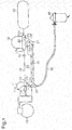
Fig. 1 is a diagram illustrating a compressed-air drying system. -
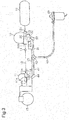
Fig. 2 is an explanatory front view showing the connecting structure of the oil mist separator and the branch pipe, which constitute the compressed-air drying system. -
Fig. 3 is a diagram illustrating a compressed-air drying system of a modification. -
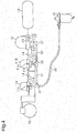
Fig. 4 is a diagram illustrating a compressed-air drying system of a modification. -
Fig. 5 is a schematic diagram illustrating a compressed-air drying system of a modification. -
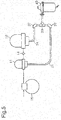
Fig. 6 is a schematic diagram illustrating a compressed-air drying system of a modification. - A compressed-air drying system according to one embodiment will now be described. In the present embodiment, the compressed-air drying system is mounted on a vehicle.
- As shown in
Fig. 1 , the compressed-air drying system includes anoil mist separator 11, anair dryer 12, and anoil separator 40, which corresponds to a reservoir. Theoil mist separator 11 has aninlet 11b and anoutlet 11c. Theinlet 11b is connected to a compressed-air delivery port of acompressor 15. Theoutlet 11c is connected to aninlet 12b of theair dryer 12 via apassage 13. Theoil mist separator 11 removes oil mist from compressed air and delivers the oil mist via theoutlet 11c. Theair dryer 12 has anoutlet 12c connected to anair tank 16. Theair dryer 12 discharges compressed dried air through theoutlet 12c. Theair tank 16 temporarily retains the compressed dried air and supplies it to loads such as air suspension systems and brake systems. - A
check valve 14 is arranged between theoil mist separator 11 and theair dryer 12. Thecheck valve 14 restricts flow the direction of which is opposite to that of the flow of compressed dried air from thecompressor 15 to theair tank 16. That is, thecheck valve 14 is closed by backflow of the compressed air from theair dryer 12 toward theoil mist separator 11. - The
air dryer 12 includes desiccant for trapping water and a filter for trapping oil mist. Theair dryer 12 removes water contained in the compressed air and oil mist, or residual oil, from the compressed air. - The
air dryer 12 includes apressure governor 20, which outputs air pressure signals to asignal supply line 25. Thepressure governor 20 detects the pressure in theair tank 16. When the pressure in theair tank 16 reaches a preset cut-out value, thepressure governor 20 outputs an air pressure signal. Theair dryer 12 further incorporates acheck valve 23. Thecheck valve 23 is arranged at theoutlet 12c and is open at normal times, when theair dryer 12 is delivering compressed dried air. - The
air dryer 12 has adrain port 12a. Thedrain port 12a is connected to theoil separator 40 so that the pressure at thedrain port 12a is the atmospheric pressure. Adrain valve device 22 is provided at thedrain port 12a. Thedrain valve device 22 is closed at normal times. Thedrain valve device 22 is opened when the output of an air pressure signal from thepressure governor 20 causes the air pressure on the upstream side of thedrain valve device 22 to exceed a predetermined pressure. When the supply of compressed air from thecompressor 15 is stopped and thedrain valve device 22 is opened, thedrain port 12a is opened. Accordingly, the compressed dried air in theair dryer 12 flows back through the desiccant to discharge water in the desiccant to the downstream side, thereby regenerating the desiccant. Also, the oil in the filter for trapping oil mist is discharged to the downstream side of the filter. Liquid that contains the water and the oil is drained to the downstream side from thedrain port 12a. - When the pressure in the
air tank 16 reaches the preset cut-out value, thedrain valve device 22 is opened and the compressed dried air in theair tank 16 acts to flow back to the outlet of theair dryer 12. This flow closes thecheck valve 23, which is incorporated in theair dryer 12. - The
oil mist separator 11 includes a trapping portion, which is a filter, and causes compressed air to pass through the filter to trap oil mist contained in the compressed air delivered from thecompressor 15. - The
oil mist separator 11 has adrain port 11 a. Thedrain port 11 a is connected to theoil separator 40 so that the pressure at thedrain port 11a is the atmospheric pressure. Adrain valve device 21 is provided at thedrain port 11a of theoil mist separator 11. Thedrain valve device 21 has a pressuresignal input port 11e. The pressuresignal input port 11e is connected to thepressure governor 20 via thesignal supply line 25. An air pressure signal output by thepressure governor 20 is delivered to the pressuresignal input port 11e via thesignal supply line 25. When the air pressure signal is input to the pressuresignal input port 11e, compressed air is supplied to thedrain valve device 21 of theoil mist separator 11. When the pressure on the upstream side of thedrain valve device 21 exceeds a predetermined pressure, thedrain valve device 21 is opened. For illustrative purposes, the pressuresignal input port 11e and pipes connected thereto are shown in a schematic manner. - When the
drain valve device 21 of theoil mist separator 11 is opened, the compressed air in theoil mist separator 11 flows back through the filter. The compressed air that flows back through the filter discharges oil trapped in the filter to the downstream side. The oil discharged to the downstream side of the filter is drained as liquid through thedrain port 11a. - In the present embodiment, the
signal supply line 25 is also connected to thecompressor 15. When receiving an air pressure signal, thecompressor 15 is switched from a mode for continuing to supply compressed air to a mode for stopping supply of compressed air, for example, through idling. - The
oil separator 40 includes a separating portion, which is a filter, a reservoir for storing liquid, and a discharge port. The filter traps oil contained in the compressed air discharged from theoil mist separator 11 and theair dryer 12. The discharge port discharges the compressed air that has passed through the filter to the atmosphere. The compressed air, which has been cleaned by passing through the filter, is discharged to the atmosphere. - Next, the structure of the passage will be described that drains the liquid drained from the
oil mist separator 11 and the liquid drained from theair dryer 12 to theoil separator 40. Thedrain port 11a of theoil mist separator 11 is connected to abranch pipe 30 that has three ports. Thedrain port 12a of theair dryer 12 is connected to one end of anupstream hose 31 via an upstream drain passage, which is an L-shapedcoupling pipe 37. The other end of theupstream hose 31 is connected to one of the ports of thebranch pipe 30. Another port of thebranch pipe 30 is connected to a drain passage, which is acommon hose 32. Thecommon hose 32 connects thebranch pipe 30 to theoil separator 40. That is, theoil mist separator 11 and theair dryer 12 share thecommon hose 32. Thebranch pipe 30 and theupstream hose 31 constitute a connecting portion that connects theoil mist separator 11 and theair dryer 12 to a common drain passage. - As shown in
Fig. 2 , thebranch pipe 30 includes a T-shaped pipe joint 33 andhose connecting portions upstream hose 31 and thecommon hose 32 to each other. Acoupling portion 36 is provided between thedrain port 11a of theoil mist separator 11 and the pipe joint 33. Thecoupling portion 36 is directly connected to thedrain port 11a. Thecoupling portion 36 has anexternal thread portion 36a at the distal end. Theexternal thread portion 36a is screwed into an internal thread portion (not shown) inside thedrain port 11a, so that thebranch pipe 30 is suspended from theoil mist separator 11. Thebranch pipe 30 has afirst inlet 30a, which is connected to theoil mist separator 11, asecond inlet 30b, which is connected to the outlet of theupstream hose 31, and anoutlet 30c, which is connected to the inlet of thecommon hose 32. - The
first inlet 30a, which is connected to thedrain port 11a of theoil mist separator 11, and theoutlet 30c are connected to each other via a straight passage formed by thecoupling portion 36, the pipe joint 33, and thehose connecting portion 35. That is, the passage from thefirst inlet 30a to theoutlet 30c of thebranch pipe 30 is straight. In contrast, thesecond inlet 30b, which is connected to thedrain port 12a of theair dryer 12, and theoutlet 30c are connected to each other via a bent passage. That is, the passage from thesecond inlet 30b to theoutlet 30c is crooked. Further, thedrain port 11a of theoil mist separator 11 is connected to the inlet of theoil separator 40 via a passage formed by thebranch pipe 30 and thecommon hose 32. In contrast, thedrain port 12a of theair dryer 12 is connected to the inlet of theoil separator 40 via a passage formed by thecoupling pipe 37, theupstream hose 31, thebranch pipe 30, and thecommon hose 32. That is, the passage length from theoil mist separator 11 to theoil separator 40 is shorter than the passage length from theair dryer 12 to theoil separator 40. Thus, the pressure loss that occurs when liquid is drained from theoil mist separator 11 is less than the pressure loss that occurs when liquid is drained from theair dryer 12. - Operation of the compressed-air drying system will now be described. During the loading mode operation for removing oil mist and water from compressed air, the compressed air delivered from the
compressor 15 flows into theoil mist separator 11 and passes through the filter, so that oil mist is trapped. The compressed air delivered from theoil mist separator 11 flows into theair dryer 12. When the compressed air passes through theair dryer 12, water and residual oil mist in the compressed air are trapped. The compressed dried air delivered from theair dryer 12 is stored in theair tank 16. - When the pressure in the
air tank 16 reaches the preset cut-out value, the unloading mode operation is executed. In the unloading mode operation, thepressure governor 20 outputs an air pressure signal. In the present embodiment, when the air pressure signal is output, thedrain valve device 21 of theoil mist separator 11 is opened before thedrain valve device 22. For example, the valve opening pressure of thedrain valve device 21 of theoil mist separator 11 may be set lower than the valve opening pressure of thedrain valve device 22 of theair dryer 12, so that thedrain valve device 21 of theoil mist separator 11 is opened before thedrain valve device 22. The valve opening pressures of thedrain valve devices drain valve devices - When the
drain valve device 21 is opened, the compressed air in theoil mist separator 11 flows back through the filter and discharges the oil in the filter to the downstream side. The oil and the like discharged to the downstream side of the filter is drained as liquid through thedrain port 11a. The liquid drained from thedrain port 11a flows into thecommon hose 32 via thebranch pipe 30 and is drained to theoil separator 40. - As described above, the pressure loss that occurs when liquid is drained from the
oil mist separator 11 is reduced compared to that when liquid is drained from theair dryer 12. Thus, the compressed air quickly flows through the filter, increasing the oil discharge efficiency from theoil mist separator 11. - The
drain valve device 22 of theair dryer 12 is opened by the air pressure signal. Then, the back flow of the compressed dried air from theair tank 16 closes thecheck valve 23 incorporated in theair dryer 12. As a result, the compressed air in theair dryer 12 flows back through the desiccant and the filter, so that liquid containing water is drained from thedrain port 12a. At this time, since the liquid has already been drained from theoil mist separator 11, fluid is drawn to the downstream side in thebranch pipe 30 and theupstream hose 31, so that thebranch pipe 30 and theupstream hose 31 are depressurized. This facilitates drainage of liquid from theair dryer 12. The liquid drained from theair dryer 12 is collected in theoil separator 40 via theupstream hose 31, thebranch pipe 30, and thecommon hose 32. The above described separating portion separates water, oil, and the like from air in the liquid collected by theoil separator 40. - When the pressure in the
air tank 16 reaches the preset cut-in value, thepressure governor 20 stops outputting the air pressure signal. As a result, thedrain valve devices compressor 15 is activated, so that the loading mode operation is started. - As described above, the
drain valve device 21 of theoil mist separator 11, of which the purge volume is small, is opened first and the liquid is drained preferentially. This limits the pressure loss that occurs when theoil mist separator 11 drains the liquid and also the pressure loss that occurs when thedrain valve device 22 of theair dryer 12 is opened to drain the liquid after theoil mist separator 11. Particularly, in a case in which thebranch pipe 30 is connected to thedrain port 11a of theoil mist separator 11, the pressure loss is reduced significantly. - The
oil mist separator 11 and theair dryer 12 share thecommon hose 32 and theoil separator 40. Compared to a configuration in which anoil separator 40 is provided for each of theoil mist separator 11 and theair dryer 12, the space occupied by the compressed-air drying system is reduced. Thus, even a vehicle with a limited installation space can mount theoil separator 40, which collects liquid drained from theoil mist separator 11. Further, since thebranch pipe 30 is connected to thedrain port 11a of theoil mist separator 11, the number of components is reduced compared to a case in which, for example, a hose is connected to thedrain port 11a of theoil mist separator 11, and this hose is connected to theupstream hose 31. Also, since thebranch pipe 30 is directly connected to theoil mist separator 11 to be suspended from theoil mist separator 11, no structure is required for fixing thebranch pipe 30 to the vehicle body. - The above described connecting structure allows the
oil separator 40 to be easily connected to theoil mist separator 11, which has already been installed in the vehicle. When theoil mist separator 11 and theoil separator 40 are connected to each other, thebranch pipe 30 is coupled to theoil mist separator 11. Theupstream hose 31 connected to theair dryer 12 or another hose is connected to thesecond inlet 30b of thebranch pipe 30 of theoil mist separator 11, and theoutlet 30c of thebranch pipe 30 is connected theoil separator 40 with thecommon hose 32. This allows the existingoil separator 40 to be effectively utilized. - As described above, the present embodiment achieves the following advantages.
- (1) Since the
drain port 11a of theoil mist separator 11 is connected to theoil separator 40 via thebranch pipe 30 and thecommon hose 32, the liquid drained from theoil mist separator 11 can be collected. Also, since theoil mist separator 11 and theair dryer 12 share thecommon hose 32 and theoil separator 40, the space occupied by the compressed-air drying system is reduced. - (2) The
first inlet 30a of thebranch pipe 30 is directly connected to thedrain port 11a of theoil mist separator 11. Thus, the number of components is reduced compared to a case in which, for example, an upstream hose connected to theoil mist separator 11 and theupstream hose 31 are coupled to each other with a branch pipe. - (3) The
first inlet 30a, to which theoil mist separator 11 is connected, and theoutlet 30c of thebranch pipe 30 are connected to each other by the straight passage. This reduces the pressure loss when theoil mist separator 11, which has a small purge volume, drains liquid, allowing the liquid to be discharged preferentially. - (4) The
drain valve device 22 of theair dryer 12 is connected to thedrain valve device 21 of theoil mist separator 11 by thesignal supply line 25. This allows thedrain valve devices pressure governor 20. The valve opening pressure of theoil mist separator 11 is lower than the valve opening pressure of theair dryer 12. Thus, when the air pressure signal is output, theoil mist separator 11 first drains liquid before theair dryer 12. This allows theair dryer 12 to easily drain liquid. - The above described embodiment may be modified as follows.
- The connecting structure of the
oil mist separator 11 and theair dryer 12 with theoil separator 40 may be changed as illustrated inFig. 3 . That is, the connecting structure may include acoupling pipe 44 and anupstream hose 41, which are connected to theoil mist separator 11, acoupling pipe 37 and anupstream hose 31, which are connected to theair dryer 12, a T-shapedbranch pipe 42, which connects thehoses common hose 43, which is connected to the outlet of thebranch pipe 30. Thebranch pipe 42 is fixed to the vehicle body. Although having a greater number of components than the structure of the above illustrated embodiment, this structure may be more advantageous when the space below thedrain port 11a of theoil mist separator 11 is limited. - As shown in
Fig. 4 , twooil mist separators 11A, 11 B may be arranged between thecompressor 15 and theair tank 16. When two or moreoil mist separators 11 are provided, thedrain port 11a of the one closest to thecompressor 15 is connected to thefirst inlet 30a of thebranch pipe 30, and the outlet of thebranch pipe 30 and theoil separator 40 are connected to each other by thecommon hose 32. Thesecond inlet 30b of thebranch pipe 30 and thedrain port 11 d of theoil mist separator 11 B on the downstream side are connected to each other by ahose 51 and T-shapedbranch pipe 50. Thebranch pipe 50 is either fixed to the vehicle body or suspended from theoil mist separator 11 B as shown inFig. 2 . Further, the discharge port of theoil mist separator 11 B on the downstream side and thedrain port 12a of theair dryer 12 are connected to each other by thebranch pipe 50 and ahose 52. The passage length to theoil separator 40 increases in the order of the oil mist separator 11 A on the upstream side, theoil mist separator 11 B on the downstream side, and theair dryer 12. Accordingly, the pressure loss at drainage of liquid increases in the same order. During the unloading mode operation, liquid is drained from the oil mist separator 11A on the upstream side, theoil mist separator 11B on the downstream side, and theair dryer 12 in order. As described above, the oil mist separator 11A closest to thecompressor 15 reduces the pressure loss when discharging liquid. This reduces the pressure loss of the otheroil mist separator 11 B and theair dryer 12. Thebranch pipe 30 is also connected to thedrain port 11d of theoil mist separator 11 B and thedrain port 12a of theair dryer 12. - As shown in
Fig. 5 , thebranch pipe 30 may be provided in the vicinity of theoil separator 40. For example, theupstream hose 41, which is connected to theoil mist separator 11, may be connected to thebranch pipe 30 via thecoupling pipe 37. Further, theupstream hose 31, which is connected to theair dryer 12, may be connected to thebranch pipe 30 via thecoupling pipe 37. InFig. 5 , thesignal supply line 25 and the like are omitted. - The
air dryer 12 is configured to include a filter for trapping oil mist. However, the filter may be omitted depending on the oil trapping performance of theoil mist separator 11. - The
air dryer 12 is configured to incorporate thecheck valve 23. However, any other valve device may be employed at the outlet of theair dryer 12 as long as that valve device is configured to close during the unloading mode operation. Thecheck valve 23, which is incorporated in theair dryer 12, may be located outside theair dryer 12 and arranged between the outlet of theair dryer 12 and theair tank 16. - The
check valve 14, which is arranged between theoil mist separator 11 and theair dryer 12, may be incorporated in theoil mist separator 11. In this case, thecheck valve 14 is preferably arranged in the vicinity of the outlet of theoil mist separator 11. - In the above illustrated embodiment, the
drain valve device 21 of theoil mist separator 11 is configured to be opened by an air pressure signal from thepressure governor 20 of theair dryer 12. However, theoil mist separator 11 may be provided with a dedicated pressure governor. - In the above illustrated embodiment, the
drain valve device 21 of theoil mist separator 11 is configured to be opened prior to thedrain valve device 22 of theair dryer 12. However, thedrain valve device 22 of theair dryer 12 may be opened first. In this case, thedrain port 12a of theair dryer 12 is connected to thebranch pipe 30, and thedrain port 11a of theoil mist separator 11 is connected to theupstream hose 31. - In the above illustrated embodiment, the
oil separator 40, which separates liquid from compressed air, is used as a reservoir. However, any structure that stores liquid without discharging it onto the road surface may be employed as a reservoir. For example, it is possible to use a tank that has no filter and simply stores liquid drained from thecommon hose 32. - In the above illustrated embodiment, the
upstream hose 31 and thebranch pipe 30 constitute the connecting portion that connects thedrain port 12a of theair dryer 12, thedrain port 11 a of theoil mist separator 11, and thecommon hose 32 to one another. However, any other members may constitute the connecting portion as long as those members achieve the passage structure similar to that in the above illustrated embodiment. For example, a unit obtained by integrating theupstream hose 31 and thebranch pipe 30 may be employed. - As shown in
Fig. 6 , thedrain port 11a of theoil mist separator 11 and an inlet of theoil separator 40 may be connected to each other by ahose 60. Also, thedrain port 12a of theair dryer 12 and another inlet of theoil separator 40 may be connected to each other by ahose 61 that is different from thehose 60 connected to theoil mist separator 11. Even with this configuration, theoil separator 40 is allowed to collect liquid drained not only from theair dryer 12, but also from theoil mist separator 11. - In the above illustrated embodiment, the oil mist separator is provided with a filter for trapping oil mist. However, oil mist may be separated, for example, through centrifuge separation or heat exchange. In any of these cases, the
branch pipe 30 or theupstream hose 41 is connected to a drain port for draining liquid, which is the oil separated from compressed air. - In the above illustrated embodiment, the present invention is applied to a compressed-air drying system mounted on a vehicle. However, the present invention may also be applicable to a system for other mobile bodies with engines such as ships and aircrafts.
- 11, 11A, 11B...Oil Mist Separator; 11a...Drain Port; 11b...lnlet; 11c...Outlet; 11d...Drain Port; 12...Air Dryer; 12a...Drain Port; 12b...lnlet; 12c...Outlet; 13...Passage, 14...Check Valve; 15...Compressor: 16...Air Tank; 20...Pressure Governor; 21, 22...Drain Valve Device; 23... Check Valve; 25... Signal Supply Passage; 30...Branch Pipe; 30a... First Inlet; 30b... Second Inlet; 30c...Outlet; 31...Upstream Hose; 32...Common Hose; 33...Pipe Joint; 34...Hose Connecting Portion; 35...Hose Connecting Portion; 36... Coupling Portion; 37...Coupling Pipe; 40...Oil Separator; 41... Upstream Hose; 42... Branch Pipe; 43... Common Hose; 44...Coupling Pipe; 50... Branch Pipe; 51, 52, 60, 61...Hose
Claims (6)
- A compressed-air drying system configured to remove oil and water contained in compressed air delivered from a compressor, the system comprising:an air dryer including desiccant and a drain port configured to drain liquid generated through regeneration of the desiccant;an oil mist separator that includesa trapping portion configured to trap oil contained, as oil mist, in the compressed air, anda drain port configured to drain liquid containing the trapped oil,wherein the oil mist separator is provided in a passage between the compressor and the air dryer; anda reservoir configured to store the liquid drained from the air dryer and the liquid drained from the oil mist separator,wherein the drain port of the air dryer and the drain port of the oil mist separator are connected to the reservoir.
- The compressed-air drying system according to claim 1, further comprising:a drain passage configured to drain, to the reservoir, the liquid drained from the air dryer and the liquid drained from the oil mist separator; anda connecting portion that connects, to the drain passage, the drain port of the air dryer and the drain port of the oil mist separator.
- The compressed-air drying system according to claim 2, wherein
the drain port of the air dryer is connected to an upstream drain passage configured to drain the liquid drained from the air dryer to a downstream side, and
the connecting portion includesa first inlet connected to the drain port of the oil mist separator,a second inlet connected to the upstream drain passage, andan outlet connected to the drain passage. - The compressed-air drying system according to claim 3, wherein the first inlet and the outlet of the connecting portion are connected to each other by a straight passage.
- The compressed-air drying system according to claim 3 or 4, wherein
the oil mist separator is one of a plurality of oil mist separators arranged between the air dryer and the compressor, and
the drain port of the oil mist separator that is closest to the compressor is connected to the first inlet of the connecting portion. - The compressed-air drying system according to any one of claims 1 to 5, wherein
the air dryer includesa pressure governor configured to output an air pressure signal to a supply passage, anda drain valve device configured to be opened by the air pressure signal,the oil mist separator includes a drain valve device configured to be opened by the air pressure signal output by the pressure governor,
the drain valve device of the air dryer is connected to the drain valve device of the oil mist separator via the supply passage, and
one of the drain valve device of the oil mist separator and the drain valve device of the air dryer is configured to be opened prior to the other.
Applications Claiming Priority (2)
| Application Number | Priority Date | Filing Date | Title |
|---|---|---|---|
| JP2014109128 | 2014-05-27 | ||
| PCT/JP2015/065031 WO2015182582A1 (en) | 2014-05-27 | 2015-05-26 | Compressed-air drying system |
Publications (3)
| Publication Number | Publication Date |
|---|---|
| EP3150271A1 true EP3150271A1 (en) | 2017-04-05 |
| EP3150271A4 EP3150271A4 (en) | 2018-04-18 |
| EP3150271B1 EP3150271B1 (en) | 2024-05-15 |
Family
ID=54698907
Family Applications (1)
| Application Number | Title | Priority Date | Filing Date |
|---|---|---|---|
| EP15799346.0A Active EP3150271B1 (en) | 2014-05-27 | 2015-05-26 | Compressed-air drying system |
Country Status (5)
| Country | Link |
|---|---|
| US (1) | US10369516B2 (en) |
| EP (1) | EP3150271B1 (en) |
| JP (1) | JP6876433B2 (en) |
| CN (1) | CN106659966B (en) |
| WO (1) | WO2015182582A1 (en) |
Cited By (1)
| Publication number | Priority date | Publication date | Assignee | Title |
|---|---|---|---|---|
| CN111841191A (en) * | 2020-06-29 | 2020-10-30 | 浙江固特气动科技股份有限公司 | Compressed air filter |
Families Citing this family (7)
| Publication number | Priority date | Publication date | Assignee | Title |
|---|---|---|---|---|
| US10843112B2 (en) * | 2014-08-29 | 2020-11-24 | Nabtesco Automotive Corporation | Oil separator and compressed air drying system |
| CN107300114A (en) * | 2017-08-14 | 2017-10-27 | 宁波晨光威腾自动化机械有限公司 | Oil sprayer is filtered in integrated pressure regulation |
| KR102602424B1 (en) * | 2018-10-11 | 2023-11-14 | 현대자동차주식회사 | System and method for removing residual pressure in the motor driven air compressor management system |
| JP6826144B2 (en) * | 2019-03-19 | 2021-02-03 | 日本エアードライヤー販売株式会社 | Compressed air condensing method and compressed air condensing device |
| CN113085819B (en) * | 2021-05-10 | 2022-08-30 | 浙江吉利控股集团有限公司 | Automobile, automobile braking energy recovery method and computer readable storage medium |
| CN115503776A (en) * | 2022-09-16 | 2022-12-23 | 中车大同电力机车有限公司 | a wind source system |
| JP7688935B2 (en) * | 2023-08-29 | 2025-06-05 | 株式会社フクハラ | Drain discharge device |
Family Cites Families (18)
| Publication number | Priority date | Publication date | Assignee | Title |
|---|---|---|---|---|
| JPS6144218U (en) * | 1984-08-21 | 1986-03-24 | 株式会社ナブコ | Compressed air storage tank with compressed air dryer |
| CH666899A5 (en) * | 1986-05-09 | 1988-08-31 | Sika Ag | REACTIVE MELT ADHESIVE. |
| US4892569A (en) * | 1987-02-23 | 1990-01-09 | Nippon Air Brake Co., Ltd. | Compressed air pressure supply system |
| JPH0618572Y2 (en) * | 1987-04-02 | 1994-05-18 | 日野自動車工業株式会社 | Vehicle compressed air purification device |
| JPH0646496Y2 (en) * | 1988-09-28 | 1994-11-30 | 株式会社ナブコ | Compressed air source device |
| AT394167B (en) * | 1990-03-21 | 1992-02-10 | Jenbacher Werke Ag | Compressed-air device, particularly for mobile compressed- air systems |
| DE4109177A1 (en) * | 1991-03-20 | 1992-09-24 | Knorr Bremse Ag | COMPRESSED AIR SUPPLY DEVICE FOR COMPRESSED AIR SYSTEMS OF VEHICLES |
| JP2592875Y2 (en) * | 1993-04-07 | 1999-03-31 | 三輪精機株式会社 | Air dryer device |
| JPH10500053A (en) * | 1993-05-26 | 1998-01-06 | エー・ピー・システムス(オーストラリア)プロプライアタリー・リミテッド | Air drying purification system |
| JPH074880U (en) * | 1993-06-16 | 1995-01-24 | 株式会社ナブコ | Oil mist separator |
| JPH0710478U (en) * | 1993-07-23 | 1995-02-14 | 三輪精機株式会社 | Oil discharge device for compressed air passages for vehicles |
| WO2000074819A1 (en) * | 1999-06-04 | 2000-12-14 | Flair Corporation | Rotating drum adsorber process and system |
| US20050045041A1 (en) * | 2003-08-29 | 2005-03-03 | Hechinger Glenn R. | Removable cartridge for swing-type adsorption system |
| JP2006212610A (en) * | 2005-02-03 | 2006-08-17 | Fukuhara Co Ltd | Apparatus for making dry compressed air |
| US7857882B1 (en) * | 2007-12-13 | 2010-12-28 | Johnson Welded Products Inc. | Water and oil mist elimination apparatus for a vehicular compressed air storage system |
| JP5542388B2 (en) * | 2009-08-11 | 2014-07-09 | ナブテスコオートモーティブ株式会社 | Air dryer |
| JP2013234632A (en) | 2012-05-10 | 2013-11-21 | Nabtesco Automotive Corp | Oil separator |
| JP6138530B2 (en) * | 2013-03-15 | 2017-05-31 | 日野自動車株式会社 | Air supply system |
-
2015
- 2015-05-26 WO PCT/JP2015/065031 patent/WO2015182582A1/en not_active Ceased
- 2015-05-26 CN CN201580026506.2A patent/CN106659966B/en active Active
- 2015-05-26 EP EP15799346.0A patent/EP3150271B1/en active Active
- 2015-05-26 JP JP2016523502A patent/JP6876433B2/en active Active
- 2015-05-26 US US15/311,702 patent/US10369516B2/en active Active
Cited By (2)
| Publication number | Priority date | Publication date | Assignee | Title |
|---|---|---|---|---|
| CN111841191A (en) * | 2020-06-29 | 2020-10-30 | 浙江固特气动科技股份有限公司 | Compressed air filter |
| CN111841191B (en) * | 2020-06-29 | 2021-09-28 | 浙江固特气动科技股份有限公司 | Compressed air filter |
Also Published As
| Publication number | Publication date |
|---|---|
| EP3150271B1 (en) | 2024-05-15 |
| US20170157558A1 (en) | 2017-06-08 |
| US10369516B2 (en) | 2019-08-06 |
| CN106659966A (en) | 2017-05-10 |
| JP6876433B2 (en) | 2021-05-26 |
| EP3150271A4 (en) | 2018-04-18 |
| CN106659966B (en) | 2019-09-03 |
| WO2015182582A1 (en) | 2015-12-03 |
| JPWO2015182582A1 (en) | 2017-04-20 |
Similar Documents
| Publication | Publication Date | Title |
|---|---|---|
| EP3150271B1 (en) | Compressed-air drying system | |
| JP6373757B2 (en) | Compressed air dryer | |
| CN111169504B (en) | Wind source device for rail transit vehicle | |
| US10099159B2 (en) | Oil separator and drain discharge system | |
| US8114199B2 (en) | Sweep air system for membrane air dryer | |
| US9346334B2 (en) | Air supply device for a vehicle having pneumatic devices | |
| JP6153223B2 (en) | Air supply system | |
| JP6280842B2 (en) | Oil separator | |
| JP6609550B2 (en) | Oil separator and vehicle oil separation system | |
| US20210046419A1 (en) | Air dryer with prefiltration stage bypass | |
| JP6138530B2 (en) | Air supply system | |
| EP3611377B1 (en) | Air supply circuit | |
| JP2024040147A (en) | oil separator | |
| CN108290568B (en) | Compressed air preparation device and method for operating a compressed air preparation device | |
| CN203637810U (en) | Integral type air supply treatment unit | |
| CN108568194A (en) | Flow-optimized dehydrating cartridge | |
| JPS60102920A (en) | Drying method of compressed air | |
| JP2016050521A (en) | Oil separator | |
| JPH10180024A (en) | Drain removal device | |
| JP7476110B2 (en) | Air Supply System | |
| JP5967825B2 (en) | Air supply system | |
| JPS60104786A (en) | Compressed air source with dryer |
Legal Events
| Date | Code | Title | Description |
|---|---|---|---|
| STAA | Information on the status of an ep patent application or granted ep patent |
Free format text: STATUS: THE INTERNATIONAL PUBLICATION HAS BEEN MADE |
|
| PUAI | Public reference made under article 153(3) epc to a published international application that has entered the european phase |
Free format text: ORIGINAL CODE: 0009012 |
|
| STAA | Information on the status of an ep patent application or granted ep patent |
Free format text: STATUS: REQUEST FOR EXAMINATION WAS MADE |
|
| 17P | Request for examination filed |
Effective date: 20161221 |
|
| AK | Designated contracting states |
Kind code of ref document: A1 Designated state(s): AL AT BE BG CH CY CZ DE DK EE ES FI FR GB GR HR HU IE IS IT LI LT LU LV MC MK MT NL NO PL PT RO RS SE SI SK SM TR |
|
| AX | Request for extension of the european patent |
Extension state: BA ME |
|
| DAV | Request for validation of the european patent (deleted) | ||
| DAX | Request for extension of the european patent (deleted) | ||
| A4 | Supplementary search report drawn up and despatched |
Effective date: 20180316 |
|
| RIC1 | Information provided on ipc code assigned before grant |
Ipc: B01D 53/26 20060101ALI20180312BHEP Ipc: F04B 39/04 20060101ALI20180312BHEP Ipc: F15B 21/04 20060101AFI20180312BHEP Ipc: F04B 39/16 20060101ALI20180312BHEP Ipc: B60T 17/00 20060101ALI20180312BHEP |
|
| STAA | Information on the status of an ep patent application or granted ep patent |
Free format text: STATUS: EXAMINATION IS IN PROGRESS |
|
| 17Q | First examination report despatched |
Effective date: 20211103 |
|
| GRAP | Despatch of communication of intention to grant a patent |
Free format text: ORIGINAL CODE: EPIDOSNIGR1 |
|
| STAA | Information on the status of an ep patent application or granted ep patent |
Free format text: STATUS: GRANT OF PATENT IS INTENDED |
|
| INTG | Intention to grant announced |
Effective date: 20231204 |
|
| GRAS | Grant fee paid |
Free format text: ORIGINAL CODE: EPIDOSNIGR3 |
|
| GRAA | (expected) grant |
Free format text: ORIGINAL CODE: 0009210 |
|
| STAA | Information on the status of an ep patent application or granted ep patent |
Free format text: STATUS: THE PATENT HAS BEEN GRANTED |
|
| P01 | Opt-out of the competence of the unified patent court (upc) registered |
Effective date: 20240308 |
|
| AK | Designated contracting states |
Kind code of ref document: B1 Designated state(s): AL AT BE BG CH CY CZ DE DK EE ES FI FR GB GR HR HU IE IS IT LI LT LU LV MC MK MT NL NO PL PT RO RS SE SI SK SM TR |
|
| REG | Reference to a national code |
Ref country code: CH Ref legal event code: EP Ref country code: GB Ref legal event code: FG4D |
|
| REG | Reference to a national code |
Ref country code: IE Ref legal event code: FG4D |
|
| REG | Reference to a national code |
Ref country code: DE Ref legal event code: R096 Ref document number: 602015088716 Country of ref document: DE |
|
| REG | Reference to a national code |
Ref country code: LT Ref legal event code: MG9D |
|
| REG | Reference to a national code |
Ref country code: NL Ref legal event code: MP Effective date: 20240515 |
|
| PG25 | Lapsed in a contracting state [announced via postgrant information from national office to epo] |
Ref country code: IS Free format text: LAPSE BECAUSE OF FAILURE TO SUBMIT A TRANSLATION OF THE DESCRIPTION OR TO PAY THE FEE WITHIN THE PRESCRIBED TIME-LIMIT Effective date: 20240915 |
|
| PG25 | Lapsed in a contracting state [announced via postgrant information from national office to epo] |
Ref country code: BG Free format text: LAPSE BECAUSE OF FAILURE TO SUBMIT A TRANSLATION OF THE DESCRIPTION OR TO PAY THE FEE WITHIN THE PRESCRIBED TIME-LIMIT Effective date: 20240515 |
|
| PG25 | Lapsed in a contracting state [announced via postgrant information from national office to epo] |
Ref country code: HR Free format text: LAPSE BECAUSE OF FAILURE TO SUBMIT A TRANSLATION OF THE DESCRIPTION OR TO PAY THE FEE WITHIN THE PRESCRIBED TIME-LIMIT Effective date: 20240515 Ref country code: FI Free format text: LAPSE BECAUSE OF FAILURE TO SUBMIT A TRANSLATION OF THE DESCRIPTION OR TO PAY THE FEE WITHIN THE PRESCRIBED TIME-LIMIT Effective date: 20240515 |
|
| PG25 | Lapsed in a contracting state [announced via postgrant information from national office to epo] |
Ref country code: GR Free format text: LAPSE BECAUSE OF FAILURE TO SUBMIT A TRANSLATION OF THE DESCRIPTION OR TO PAY THE FEE WITHIN THE PRESCRIBED TIME-LIMIT Effective date: 20240816 |
|
| PG25 | Lapsed in a contracting state [announced via postgrant information from national office to epo] |
Ref country code: PT Free format text: LAPSE BECAUSE OF FAILURE TO SUBMIT A TRANSLATION OF THE DESCRIPTION OR TO PAY THE FEE WITHIN THE PRESCRIBED TIME-LIMIT Effective date: 20240916 |
|
| REG | Reference to a national code |
Ref country code: AT Ref legal event code: MK05 Ref document number: 1687125 Country of ref document: AT Kind code of ref document: T Effective date: 20240515 |
|
| PG25 | Lapsed in a contracting state [announced via postgrant information from national office to epo] |
Ref country code: NL Free format text: LAPSE BECAUSE OF FAILURE TO SUBMIT A TRANSLATION OF THE DESCRIPTION OR TO PAY THE FEE WITHIN THE PRESCRIBED TIME-LIMIT Effective date: 20240515 |
|
| PG25 | Lapsed in a contracting state [announced via postgrant information from national office to epo] |
Ref country code: ES Free format text: LAPSE BECAUSE OF FAILURE TO SUBMIT A TRANSLATION OF THE DESCRIPTION OR TO PAY THE FEE WITHIN THE PRESCRIBED TIME-LIMIT Effective date: 20240515 |
|
| PG25 | Lapsed in a contracting state [announced via postgrant information from national office to epo] |
Ref country code: AT Free format text: LAPSE BECAUSE OF FAILURE TO SUBMIT A TRANSLATION OF THE DESCRIPTION OR TO PAY THE FEE WITHIN THE PRESCRIBED TIME-LIMIT Effective date: 20240515 |
|
| PG25 | Lapsed in a contracting state [announced via postgrant information from national office to epo] |
Ref country code: PL Free format text: LAPSE BECAUSE OF FAILURE TO SUBMIT A TRANSLATION OF THE DESCRIPTION OR TO PAY THE FEE WITHIN THE PRESCRIBED TIME-LIMIT Effective date: 20240515 |
|
| PG25 | Lapsed in a contracting state [announced via postgrant information from national office to epo] |
Ref country code: LV Free format text: LAPSE BECAUSE OF FAILURE TO SUBMIT A TRANSLATION OF THE DESCRIPTION OR TO PAY THE FEE WITHIN THE PRESCRIBED TIME-LIMIT Effective date: 20240515 |
|
| PG25 | Lapsed in a contracting state [announced via postgrant information from national office to epo] |
Ref country code: PT Free format text: LAPSE BECAUSE OF FAILURE TO SUBMIT A TRANSLATION OF THE DESCRIPTION OR TO PAY THE FEE WITHIN THE PRESCRIBED TIME-LIMIT Effective date: 20240916 Ref country code: PL Free format text: LAPSE BECAUSE OF FAILURE TO SUBMIT A TRANSLATION OF THE DESCRIPTION OR TO PAY THE FEE WITHIN THE PRESCRIBED TIME-LIMIT Effective date: 20240515 Ref country code: NO Free format text: LAPSE BECAUSE OF FAILURE TO SUBMIT A TRANSLATION OF THE DESCRIPTION OR TO PAY THE FEE WITHIN THE PRESCRIBED TIME-LIMIT Effective date: 20240815 Ref country code: NL Free format text: LAPSE BECAUSE OF FAILURE TO SUBMIT A TRANSLATION OF THE DESCRIPTION OR TO PAY THE FEE WITHIN THE PRESCRIBED TIME-LIMIT Effective date: 20240515 Ref country code: LV Free format text: LAPSE BECAUSE OF FAILURE TO SUBMIT A TRANSLATION OF THE DESCRIPTION OR TO PAY THE FEE WITHIN THE PRESCRIBED TIME-LIMIT Effective date: 20240515 Ref country code: IS Free format text: LAPSE BECAUSE OF FAILURE TO SUBMIT A TRANSLATION OF THE DESCRIPTION OR TO PAY THE FEE WITHIN THE PRESCRIBED TIME-LIMIT Effective date: 20240915 Ref country code: HR Free format text: LAPSE BECAUSE OF FAILURE TO SUBMIT A TRANSLATION OF THE DESCRIPTION OR TO PAY THE FEE WITHIN THE PRESCRIBED TIME-LIMIT Effective date: 20240515 Ref country code: GR Free format text: LAPSE BECAUSE OF FAILURE TO SUBMIT A TRANSLATION OF THE DESCRIPTION OR TO PAY THE FEE WITHIN THE PRESCRIBED TIME-LIMIT Effective date: 20240816 Ref country code: FI Free format text: LAPSE BECAUSE OF FAILURE TO SUBMIT A TRANSLATION OF THE DESCRIPTION OR TO PAY THE FEE WITHIN THE PRESCRIBED TIME-LIMIT Effective date: 20240515 Ref country code: ES Free format text: LAPSE BECAUSE OF FAILURE TO SUBMIT A TRANSLATION OF THE DESCRIPTION OR TO PAY THE FEE WITHIN THE PRESCRIBED TIME-LIMIT Effective date: 20240515 Ref country code: BG Free format text: LAPSE BECAUSE OF FAILURE TO SUBMIT A TRANSLATION OF THE DESCRIPTION OR TO PAY THE FEE WITHIN THE PRESCRIBED TIME-LIMIT Effective date: 20240515 Ref country code: AT Free format text: LAPSE BECAUSE OF FAILURE TO SUBMIT A TRANSLATION OF THE DESCRIPTION OR TO PAY THE FEE WITHIN THE PRESCRIBED TIME-LIMIT Effective date: 20240515 Ref country code: RS Free format text: LAPSE BECAUSE OF FAILURE TO SUBMIT A TRANSLATION OF THE DESCRIPTION OR TO PAY THE FEE WITHIN THE PRESCRIBED TIME-LIMIT Effective date: 20240815 |
|
| REG | Reference to a national code |
Ref country code: CH Ref legal event code: PL |
|
| PG25 | Lapsed in a contracting state [announced via postgrant information from national office to epo] |
Ref country code: DK Free format text: LAPSE BECAUSE OF FAILURE TO SUBMIT A TRANSLATION OF THE DESCRIPTION OR TO PAY THE FEE WITHIN THE PRESCRIBED TIME-LIMIT Effective date: 20240515 |
|
| PG25 | Lapsed in a contracting state [announced via postgrant information from national office to epo] |
Ref country code: LU Free format text: LAPSE BECAUSE OF NON-PAYMENT OF DUE FEES Effective date: 20240526 |
|
| PG25 | Lapsed in a contracting state [announced via postgrant information from national office to epo] |
Ref country code: EE Free format text: LAPSE BECAUSE OF FAILURE TO SUBMIT A TRANSLATION OF THE DESCRIPTION OR TO PAY THE FEE WITHIN THE PRESCRIBED TIME-LIMIT Effective date: 20240515 |
|
| PG25 | Lapsed in a contracting state [announced via postgrant information from national office to epo] |
Ref country code: CZ Free format text: LAPSE BECAUSE OF FAILURE TO SUBMIT A TRANSLATION OF THE DESCRIPTION OR TO PAY THE FEE WITHIN THE PRESCRIBED TIME-LIMIT Effective date: 20240515 |
|
| PG25 | Lapsed in a contracting state [announced via postgrant information from national office to epo] |
Ref country code: SK Free format text: LAPSE BECAUSE OF FAILURE TO SUBMIT A TRANSLATION OF THE DESCRIPTION OR TO PAY THE FEE WITHIN THE PRESCRIBED TIME-LIMIT Effective date: 20240515 Ref country code: RO Free format text: LAPSE BECAUSE OF FAILURE TO SUBMIT A TRANSLATION OF THE DESCRIPTION OR TO PAY THE FEE WITHIN THE PRESCRIBED TIME-LIMIT Effective date: 20240515 |
|
| PG25 | Lapsed in a contracting state [announced via postgrant information from national office to epo] |
Ref country code: SM Free format text: LAPSE BECAUSE OF FAILURE TO SUBMIT A TRANSLATION OF THE DESCRIPTION OR TO PAY THE FEE WITHIN THE PRESCRIBED TIME-LIMIT Effective date: 20240515 |
|
| PG25 | Lapsed in a contracting state [announced via postgrant information from national office to epo] |
Ref country code: SM Free format text: LAPSE BECAUSE OF FAILURE TO SUBMIT A TRANSLATION OF THE DESCRIPTION OR TO PAY THE FEE WITHIN THE PRESCRIBED TIME-LIMIT Effective date: 20240515 Ref country code: SK Free format text: LAPSE BECAUSE OF FAILURE TO SUBMIT A TRANSLATION OF THE DESCRIPTION OR TO PAY THE FEE WITHIN THE PRESCRIBED TIME-LIMIT Effective date: 20240515 Ref country code: RO Free format text: LAPSE BECAUSE OF FAILURE TO SUBMIT A TRANSLATION OF THE DESCRIPTION OR TO PAY THE FEE WITHIN THE PRESCRIBED TIME-LIMIT Effective date: 20240515 Ref country code: LU Free format text: LAPSE BECAUSE OF NON-PAYMENT OF DUE FEES Effective date: 20240526 Ref country code: EE Free format text: LAPSE BECAUSE OF FAILURE TO SUBMIT A TRANSLATION OF THE DESCRIPTION OR TO PAY THE FEE WITHIN THE PRESCRIBED TIME-LIMIT Effective date: 20240515 Ref country code: DK Free format text: LAPSE BECAUSE OF FAILURE TO SUBMIT A TRANSLATION OF THE DESCRIPTION OR TO PAY THE FEE WITHIN THE PRESCRIBED TIME-LIMIT Effective date: 20240515 Ref country code: CZ Free format text: LAPSE BECAUSE OF FAILURE TO SUBMIT A TRANSLATION OF THE DESCRIPTION OR TO PAY THE FEE WITHIN THE PRESCRIBED TIME-LIMIT Effective date: 20240515 Ref country code: CH Free format text: LAPSE BECAUSE OF NON-PAYMENT OF DUE FEES Effective date: 20240531 |
|
| PG25 | Lapsed in a contracting state [announced via postgrant information from national office to epo] |
Ref country code: IT Free format text: LAPSE BECAUSE OF FAILURE TO SUBMIT A TRANSLATION OF THE DESCRIPTION OR TO PAY THE FEE WITHIN THE PRESCRIBED TIME-LIMIT Effective date: 20240515 Ref country code: MC Free format text: LAPSE BECAUSE OF FAILURE TO SUBMIT A TRANSLATION OF THE DESCRIPTION OR TO PAY THE FEE WITHIN THE PRESCRIBED TIME-LIMIT Effective date: 20240515 |
|
| REG | Reference to a national code |
Ref country code: DE Ref legal event code: R097 Ref document number: 602015088716 Country of ref document: DE |
|
| REG | Reference to a national code |
Ref country code: BE Ref legal event code: MM Effective date: 20240531 |
|
| PLBE | No opposition filed within time limit |
Free format text: ORIGINAL CODE: 0009261 |
|
| STAA | Information on the status of an ep patent application or granted ep patent |
Free format text: STATUS: NO OPPOSITION FILED WITHIN TIME LIMIT |
|
| PG25 | Lapsed in a contracting state [announced via postgrant information from national office to epo] |
Ref country code: IE Free format text: LAPSE BECAUSE OF NON-PAYMENT OF DUE FEES Effective date: 20240526 |
|
| 26N | No opposition filed |
Effective date: 20250218 |
|
| PG25 | Lapsed in a contracting state [announced via postgrant information from national office to epo] |
Ref country code: SI Free format text: LAPSE BECAUSE OF FAILURE TO SUBMIT A TRANSLATION OF THE DESCRIPTION OR TO PAY THE FEE WITHIN THE PRESCRIBED TIME-LIMIT Effective date: 20240515 Ref country code: BE Free format text: LAPSE BECAUSE OF NON-PAYMENT OF DUE FEES Effective date: 20240531 |
|
| PGFP | Annual fee paid to national office [announced via postgrant information from national office to epo] |
Ref country code: DE Payment date: 20250521 Year of fee payment: 11 |
|
| PGFP | Annual fee paid to national office [announced via postgrant information from national office to epo] |
Ref country code: GB Payment date: 20250521 Year of fee payment: 11 |
|
| PGFP | Annual fee paid to national office [announced via postgrant information from national office to epo] |
Ref country code: FR Payment date: 20250528 Year of fee payment: 11 |
|
| PG25 | Lapsed in a contracting state [announced via postgrant information from national office to epo] |
Ref country code: HU Free format text: LAPSE BECAUSE OF FAILURE TO SUBMIT A TRANSLATION OF THE DESCRIPTION OR TO PAY THE FEE WITHIN THE PRESCRIBED TIME-LIMIT; INVALID AB INITIO Effective date: 20150526 |
|
| PG25 | Lapsed in a contracting state [announced via postgrant information from national office to epo] |
Ref country code: SE Free format text: LAPSE BECAUSE OF FAILURE TO SUBMIT A TRANSLATION OF THE DESCRIPTION OR TO PAY THE FEE WITHIN THE PRESCRIBED TIME-LIMIT Effective date: 20240515 |
|
| PG25 | Lapsed in a contracting state [announced via postgrant information from national office to epo] |
Ref country code: CY Free format text: LAPSE BECAUSE OF FAILURE TO SUBMIT A TRANSLATION OF THE DESCRIPTION OR TO PAY THE FEE WITHIN THE PRESCRIBED TIME-LIMIT; INVALID AB INITIO Effective date: 20150526 |