EP3150249A1 - Catheter, examination system and thrombus removing device - Google Patents
Catheter, examination system and thrombus removing device Download PDFInfo
- Publication number
- EP3150249A1 EP3150249A1 EP16196427.5A EP16196427A EP3150249A1 EP 3150249 A1 EP3150249 A1 EP 3150249A1 EP 16196427 A EP16196427 A EP 16196427A EP 3150249 A1 EP3150249 A1 EP 3150249A1
- Authority
- EP
- European Patent Office
- Prior art keywords
- optical fiber
- capillary tube
- catheter
- removing device
- thrombus
- Prior art date
- Legal status (The legal status is an assumption and is not a legal conclusion. Google has not performed a legal analysis and makes no representation as to the accuracy of the status listed.)
- Granted
Links
Images


Classifications
-
- A—HUMAN NECESSITIES
- A61—MEDICAL OR VETERINARY SCIENCE; HYGIENE
- A61B—DIAGNOSIS; SURGERY; IDENTIFICATION
- A61B18/00—Surgical instruments, devices or methods for transferring non-mechanical forms of energy to or from the body
- A61B18/18—Surgical instruments, devices or methods for transferring non-mechanical forms of energy to or from the body by applying electromagnetic radiation, e.g. microwaves
- A61B18/20—Surgical instruments, devices or methods for transferring non-mechanical forms of energy to or from the body by applying electromagnetic radiation, e.g. microwaves using laser
- A61B18/22—Surgical instruments, devices or methods for transferring non-mechanical forms of energy to or from the body by applying electromagnetic radiation, e.g. microwaves using laser the beam being directed along or through a flexible conduit, e.g. an optical fibre; Couplings or hand-pieces therefor
- A61B18/24—Surgical instruments, devices or methods for transferring non-mechanical forms of energy to or from the body by applying electromagnetic radiation, e.g. microwaves using laser the beam being directed along or through a flexible conduit, e.g. an optical fibre; Couplings or hand-pieces therefor with a catheter
-
- A—HUMAN NECESSITIES
- A61—MEDICAL OR VETERINARY SCIENCE; HYGIENE
- A61B—DIAGNOSIS; SURGERY; IDENTIFICATION
- A61B90/00—Instruments, implements or accessories specially adapted for surgery or diagnosis and not covered by any of the groups A61B1/00 - A61B50/00, e.g. for luxation treatment or for protecting wound edges
- A61B90/39—Markers, e.g. radio-opaque or breast lesions markers
-
- A—HUMAN NECESSITIES
- A61—MEDICAL OR VETERINARY SCIENCE; HYGIENE
- A61M—DEVICES FOR INTRODUCING MEDIA INTO, OR ONTO, THE BODY; DEVICES FOR TRANSDUCING BODY MEDIA OR FOR TAKING MEDIA FROM THE BODY; DEVICES FOR PRODUCING OR ENDING SLEEP OR STUPOR
- A61M25/00—Catheters; Hollow probes
- A61M25/0021—Catheters; Hollow probes characterised by the form of the tubing
- A61M25/0023—Catheters; Hollow probes characterised by the form of the tubing by the form of the lumen, e.g. cross-section, variable diameter
- A61M25/0026—Multi-lumen catheters with stationary elements
- A61M2025/0037—Multi-lumen catheters with stationary elements characterized by lumina being arranged side-by-side
-
- A—HUMAN NECESSITIES
- A61—MEDICAL OR VETERINARY SCIENCE; HYGIENE
- A61M—DEVICES FOR INTRODUCING MEDIA INTO, OR ONTO, THE BODY; DEVICES FOR TRANSDUCING BODY MEDIA OR FOR TAKING MEDIA FROM THE BODY; DEVICES FOR PRODUCING OR ENDING SLEEP OR STUPOR
- A61M5/00—Devices for bringing media into the body in a subcutaneous, intra-vascular or intramuscular way; Accessories therefor, e.g. filling or cleaning devices, arm-rests
- A61M5/007—Devices for bringing media into the body in a subcutaneous, intra-vascular or intramuscular way; Accessories therefor, e.g. filling or cleaning devices, arm-rests for contrast media
Definitions
- the present invention relates to a catheter, an examination system, and a thrombus removing device.
- a catheter is a flexible tube with a diameter of approximately 2mm and a length of approximately 1m.
- the catheter can be inserted from a femoral artery and advanced to a target site such as the heart or the brain.
- a contrast agent is supplied from the front end of the catheter, radiography can be performed.
- a catheter through a hole of which a guide wire is passed has been known.
- the catheter is inserted from a femoral region, first, the wire is first inserted in the femoral region, and then the catheter is sent out along the guide wire, whereby the catheter can be made to reach a target site.
- a catheter is inserted in the body, and a thrombolytic agent (urokinase) is released from a front-end portion thereof.
- a thrombolytic treatment using a laser beam is also known. Since the laser beam is attenuated by blood vessels, several devices have been proposed.
- the present invention has been made in view of such a problem, and an object thereof is to provide a catheter which can effectively irradiate an object with a laser beam and an examination system and a thrombus removing device which can effectively dissolve a thrombus as the object.
- a catheter according to the present invention includes: a resinous capillary tube having a hole to pass a wire therethrough; a marker attached to a front-end portion of the capillary tube; and an optical fiber which is buried in the capillary tube and whose position relative to the marker is fixed.
- the wire When the catheter is inserted from a femoral region, the wire is first inserted in the femoral region, and then the catheter is sent out along the wire, whereby the catheter is made to reach a target site.
- the marker when radiography is performed, the marker is displayed on a screen.
- a metal marker that absorbs X-rays is favorably used. Since the position of this metal marker relative to the optical fiber is fixed, the metal marker can be moved up close to the target site such as a thrombus. More specifically, since the distance between the target site and the front end of the optical fiber is known, it becomes unnecessary to use a large quantity of contrast agent and irradiate a laser beam depending on skill and intuition, and therefore an effective laser beam irradiation becomes possible.
- the catheter further includes a resin material interposed between the optical fiber and the capillary tube.
- the resin material is also bent when the catheter is curved, to suppress trace elements in blood from entering. Therefore, deterioration of the optical fiber can be prevented.
- An examination system having this catheter includes: the catheter; and a light source which emits light to be inputted to the optical fiber of the catheter.
- the light source is a laser light source, and a center wavelength ⁇ , a pulse width T, and a repetition frequency f of the laser beam are set as follows: 520 nm ⁇ ⁇ ⁇ 590 nm 1 ⁇ sec ⁇ T ⁇ 100 ⁇ sec 1 Hz ⁇ f ⁇ 10 Hz
- a laser beam can be effectively irradiated onto a target, so that a thrombus being the target can be effectively dissolved.
- Fig. 1 is a longitudinal sectional view of a catheter.
- a catheter 1 includes a resinous capillary tube 4 having a hole 3 to pass a wire 2 therethrough, a metal marker 5 attached to a front-end portion of the capillary tube 4, and an optical fiber 6 which is embedded in the capillary tube 4 and whose position relative to the metal marker 5 is fixed.
- the capillary tube 4 has a branching portion 4a, and the hole 3 passes through one branched capillary tube 4X and an optical fiber 6 passes through the other branched capillary tube 4Y.
- the annular metal marker 5 made of a metal such as platinum is fitted to the front-end portion of the capillary tube 4, and is thus fixed to the capillary tube 4.
- the metal marker 5 may be formed by plating or vapor-depositing the resin capillary tube 4 with a metal material.
- a Y-type branching adapter 7 is fixed to a base-end portion of the branched capillary tube 4X.
- the branching adapter 7 has a wire inserting through-hole 7a and a contrast agent introducing through-hole 7b, these through-holes 7a and 7b are connected at the branching capillary tube 4X side to form a common through-hole 7c, and this is connected with the hole 3 of the branched capillary tube 4X.
- the branched capillary tube 4X and the branching adapter 7 are coupled by a connector 8.
- a coupling portion 7d at the branched capillary tube 4X side of the branching adapter 7 has a screw portion 7y at the periphery and includes, at the inside, a branched capillary tube insertion hole 7x communicated with the common through-hole 7c.
- a base-end portion 4X1 of the branched capillary tube 4X is inserted in the branched capillary tube insertion hole 7x, and the periphery of the base-end portion 4X1 has a screw portion 4X1T.
- the connector 8 forms a cap being a cylinder with a bottom, has a screw portion 8a at the inner surface of its cylindrical portion, and has a screw portion 8b at the inside of an opening of its bottom portion.
- the screw portions 8a and 8b at the inside thereof are screwed with screw portions 7y and 4X1T formed on the periphery of the coupling portion 7d and the periphery of the base-end portion 4X1, whereby the branching adapter 7 is fixed to the branched capillary tube 4X.
- a connecting portion 7e at the side of a contrast agent introducing tube 9 of the branching adapter 7 has a screw portion 7f at the periphery and includes, at the inside, a contrast agent introducing tube insertion hole 7g communicated with the contrast agent introducing through-hole 7b.
- a contrast agent introducing tube insertion hole 7g communicated with the contrast agent introducing through-hole 7b.
- a base-end portion 91 of the contrast agent introducing tube 9 is inserted, and the periphery of the base-end portion 91 has a screw portion 91T.
- the connector 10 forms a cap being a cylinder with a bottom, has a screw portion 10a at the inner surface of its cylindrical portion, and has a screw portion 10b at the inside of an opening at its bottom portion.
- the screw portions 10a and 10b at the inside thereof are screwed with the screw portions 7f and 91T formed on the periphery of the coupling portion 7e and the periphery of the base-end portion 91, whereby the contrast agent introducing tube 9 is fixed to the branching adapter 7.
- a wire inserting tail-end portion 7h of the branching adaptor 7 has a screw portion 7i at the periphery and includes, on its tail-end face, a packing 11 that blocks the wire inserting through-hole 7 a.
- a tail-end cap 12 is a cylinder with a bottom, and has a screw portion 12a at the inner surface of its cylinder portion.
- the screw portion 12a at the inside thereof is screwed with the screw portion 7i formed on the periphery of the wire inserting tail-end portion 7h, and the packing 11 is pressed against the wire inserting tail-end portion 7h.
- the columnar-shaped packing 11 has a wire passing hole 11a at the center, and the wire 2 passes through the wire passing hole 11a.
- the connector 13 is composed of a connector body 13X and caps 13Y and 13Z provided at both ends of the connector body 13X.
- the connector body 13X has a branched capillary tube insertion hole 13a and a ferule insertion hole 13b, and these insertion holes 13a and 13b are communicated within the connector.
- a coupling portion 13d at the branched capillary tube 4Y side of the connector body 13X has a screw portion 13y at the periphery.
- a base-end portion 4Y1 of the branched capillary tube 4Y is inserted, and the periphery of the base-end portion 4Y1 has a screw portion 4Y1T.
- a cap 13Y forms a cylinder with a bottom, has a screw portion 13Ya at the inner surface of its cylindrical portion, and has a screw portion 13Yb at the inside of its bottom portion.
- the screw portions 13Ya and 13Yb at the inside thereof are screwed with screw portions 13y and 4Y1T formed on the periphery of the coupling portion 13d and the periphery of the base-end portion 4Y1, whereby the branched capillary tube 4Y is connected to the connector 13.
- a coupling portion 13e at the ferule side of the connector body 13X has a screw portion 13f at the periphery.
- the ferule 61a that includes the optical fiber 61 is inserted.
- a cap 13Z forms a cylinder with a bottom, and has a screw portion 13Za at the inner surface of its cylindrical portion.
- the screw portion 13Za at the inside thereof is screwed with the screw portion 13f formed at the periphery of the coupling portion 13e, whereby the ferule 61a is fixed to the connector 13. Therefore, the ferule 61a and the branched capillary tube 4Y are coupled by the connector 13, and the optical fiber 61 and the optical fiber 6 within these respective portions are optically coupled.
- a laser beam is introduced into the optical fiber 61 from a laser diode LD (light source), the laser beam is inputted to the optical fiber 6, and is emitted from the front end of the catheter 1.
- a laser diode LD light source
- the catheter 1 When the catheter 1 is inserted in the body from a femoral region, the wire 2 that slides within the capillary tube 4 is first inserted in the femoral region, and then the catheter 1 is sent out along the wire, whereby the catheter 1 is made to reach a target site.
- the metal marker 5 is displayed on a screen of an X-ray apparatus.
- the position of the metal marker 5 relative to the optical fiber 6 is fixed, and the metal marker 5 can be moved up close to the target site such as a thrombus.
- the position, in an optical fiber longitudinal direction, of a front-end face of the optical fiber 6 is coincident with the position, in an optical fiber longitudinal direction, of a front-end face of the metal marker 5, the invention is not limited thereto. More specifically, since the distance between the target site and the front end of the optical fiber 6 is known by radiography, it becomes unnecessary to use a large quantity of contrast agent and irradiate a laser beam depending on skill and intuition, and therefore an effective laser beam irradiation becomes possible.
- the front end of the optical fiber 6 can be approximated to such an extent as to contact the thrombus or up to a close range. In such a state, it becomes possible to dissolve the thrombus more safely by only irradiating a laser beam with a specific wavelength, a specific pulse width, and a repetition frequency from the optical fiber 6.
- a contrast agent (iodine containing water-soluble contrast medium) is introduced via the contrast agent introducing tube 9 according to necessity, passed through the through-holes 7b, 7c, and 3, and released from the front end of the catheter 1. Also, when the contrast agent is introduced, it is preferable to withdraw the wire 2 from the capillary tube 4 of the catheter 1.
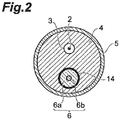
- Fig. 2 is a sectional view along arrows II-II of the catheter shown in Fig. 1 .
- the optical fiber 6 is provided in a buried condition in the resinous capillary tube (body) 4, and its longitudinal direction is coincident with a longitudinal direction of the capillary tube 4.
- the center position of the optical fiber 6 is off the center position in a section vertical to the longitudinal direction of the capillary tube 4, and the wire 2 passes through the inside of the hole 3 provided side by side with the optical fiber 6.
- the capillary tube 4 is made of a material such as Teflon (registered trademark).
- a resin material 14 is interposed between the optical fiber 6 and the capillary tube 4.
- the resin material 14 is also bent when the catheter 1 is curved, to suppress trace elements in blood from entering the optical fiber 6, so that deterioration of the optical fiber 6 can be prevented.
- the resin material 14 is an elastic material, which is formed of a silicone resin or the like.
- the optical fiber 6 may be directly buried in the capillary tube 4.
- a method for burying the optical fiber 6 is for forming a capillary tube 4 opened with one hole by metallic molding, then passing an optical fiber 6 coated with an unsolidified resin material 14 through one narrow hole, and cutting a front-end portion of the capillary tube 4 along with the optical fiber 6 after the resin material 14 is solidified. Mechanical polishing is performed for this front-end portion.
- a method for arranging an optical fiber 6 coated with a solidified resin material 14 and a molding wire such as a piano wire in a die for a capillary tube 4, introducing a capillary tube forming material into this die and solidifying the material, then withdrawing the molding wire from the capillary tube 4, and then cutting a front-end portion of the capillary tube 4 along with the optical fiber 6. Mechanical polishing is performed for this front-end portion.
- the optical fiber 6 is composed of a core 6a made of silica glass and a clad 6b located around the core 6a. A laser beam that has passed through the core 6a of the optical fiber 6 is emitted from the front-end face.
- Fig. 3 is a block diagram of an inspection system to which the catheter shown in Fig. 1 is connected.
- a thrombus can be dissolved more safely by only irradiating a laser beam with a specific wavelength, a specific pulse width, and a repetition frequency from the optical fiber 6. More specifically, the present examination system functions mainly as a thrombus removing device.
- the present examination system includes the catheter 1, the laser diode LD that emits a laser beam to be inputted to the optical fiber 6 of the catheter 1, and a drive circuit DRV of the laser diode LD.
- a center wavelength ⁇ , a pulse width T, and a repetition frequency f of the laser beam has the following relationship.
- Center wavelength ⁇ 532nm (effective wavelength: 520nm ⁇ 590nm) 1 ⁇ sec ⁇ T ⁇ 100 ⁇ sec 1 Hz ⁇ f ⁇ 10 Hz .
- the power of the laser beam is set to 10 to 100mJ.
- Laser driving conditions of the drive circuit DRV are set by a controller CON. After the catheter 1 is inserted in the body, the wire 2 is withdrawn, and a contrast agent is released from the contrast agent injector INJ into the contrast agent introducing tube 9 according to necessity. The contrast agent injector INJ is controlled by the controller CON.
- a laser light source (laser diode LD) has been exemplified as the light source
- the light source is not limited thereto and may be, for example, a light-emitting diode, a DPSS laser (Diode Pumped Solid-State Laser) or the like.
- the present invention can be used for a catheter, an examination system, and a thrombus removing device.
Landscapes
- Health & Medical Sciences (AREA)
- Surgery (AREA)
- Physics & Mathematics (AREA)
- Life Sciences & Earth Sciences (AREA)
- Heart & Thoracic Surgery (AREA)
- Medical Informatics (AREA)
- Nuclear Medicine, Radiotherapy & Molecular Imaging (AREA)
- Electromagnetism (AREA)
- Engineering & Computer Science (AREA)
- Biomedical Technology (AREA)
- Optics & Photonics (AREA)
- Otolaryngology (AREA)
- Molecular Biology (AREA)
- Animal Behavior & Ethology (AREA)
- General Health & Medical Sciences (AREA)
- Public Health (AREA)
- Veterinary Medicine (AREA)
- Laser Surgery Devices (AREA)
- Media Introduction/Drainage Providing Device (AREA)
- Radiation-Therapy Devices (AREA)
Abstract
Description
- The present invention relates to a catheter, an examination system, and a thrombus removing device.
- A catheter is a flexible tube with a diameter of approximately 2mm and a length of approximately 1m. The catheter can be inserted from a femoral artery and advanced to a target site such as the heart or the brain. When a contrast agent is supplied from the front end of the catheter, radiography can be performed.
- A catheter through a hole of which a guide wire is passed has been known. When the catheter is inserted from a femoral region, first, the wire is first inserted in the femoral region, and then the catheter is sent out along the guide wire, whereby the catheter can be made to reach a target site.
- For a thrombolytic treatment of heart and brain vessels, a catheter is inserted in the body, and a thrombolytic agent (urokinase) is released from a front-end portion thereof. Moreover, a thrombolytic treatment using a laser beam is also known. Since the laser beam is attenuated by blood vessels, several devices have been proposed.
- In a thrombolytic treatment described in the following Patent Document 1, it has been described that attenuation of a laser beam can be suppressed by advancing a laser beam into a contrast agent while releasing the contrast agent from the front-end portion of a catheter, whereby a thrombus can be dissolved. It has been provided that the laser beam is emitted from a movable optical fiber through a hole provided in the catheter.
- In a thrombolytic treatment described in the following
Patent Document 2, it has been provided that a pulsed laser radiation is emitted from the front end of an optical fiber protruded from the front-end portion of a capillary tube to cause ultrasonic vibration, whereby a thrombus can be dissolved. - Patent Document 1:
Japanese Patent Registration No. 322885 - Patent Document 2:
Japanese Translation of International Application (Kohyo) No. 2000-508938 - Meanwhile, with a conventional catheter, since the distance between a laser beam and a thrombus is unclear, a large quantity of contrast agent has been used and a laser beam has been emitted depending on skill and intuition, and thus the laser beam could not be effectively irradiated onto a target such as a thrombus.
- The present invention has been made in view of such a problem, and an object thereof is to provide a catheter which can effectively irradiate an object with a laser beam and an examination system and a thrombus removing device which can effectively dissolve a thrombus as the object.
- In order to solve the problem described above, a catheter according to the present invention includes: a resinous capillary tube having a hole to pass a wire therethrough; a marker attached to a front-end portion of the capillary tube; and an optical fiber which is buried in the capillary tube and whose position relative to the marker is fixed.
- When the catheter is inserted from a femoral region, the wire is first inserted in the femoral region, and then the catheter is sent out along the wire, whereby the catheter is made to reach a target site. In this case, when radiography is performed, the marker is displayed on a screen. As the marker, a metal marker that absorbs X-rays is favorably used. Since the position of this metal marker relative to the optical fiber is fixed, the metal marker can be moved up close to the target site such as a thrombus. More specifically, since the distance between the target site and the front end of the optical fiber is known, it becomes unnecessary to use a large quantity of contrast agent and irradiate a laser beam depending on skill and intuition, and therefore an effective laser beam irradiation becomes possible.
- It is preferable that the catheter further includes a resin material interposed between the optical fiber and the capillary tube. The resin material is also bent when the catheter is curved, to suppress trace elements in blood from entering. Therefore, deterioration of the optical fiber can be prevented.
- An examination system having this catheter includes: the catheter; and a light source which emits light to be inputted to the optical fiber of the catheter. Here, it is preferable the light source is a laser light source, and a center wavelength λ, a pulse width T, and a repetition frequency f of the laser beam are set as follows:



- In this case, since the laser beam effectively acts for thrombolysis and does not act on vessel walls, a thrombus can be dissolved efficiently and safely in a short time.
- According to the catheter, examination system, and thrombus removing device of the present invention, a laser beam can be effectively irradiated onto a target, so that a thrombus being the target can be effectively dissolved.
- Further aspects of the present disclosure as set forth in the following numbered clauses:
- Clause 1. A catheter comprising:
- a resinous capillary tube having a hole to pass a wire therethrough;
- a marker attached to a front-end portion of the capillary tube; and
- an optical fiber which is buried in the capillary tube and whose position relative to the marker is fixed.
-
Clause 2. The catheter according to Clause 1, further comprising a resin material interposed between the optical fiber and the capillary tube. -
Clause 3. An examination system comprising:- the catheter according to Clause 1; and
- a light source which emits light to be inputted to the optical fiber of the catheter.
-
Clause 4. The examination system according toClause 3, wherein
the light source is a laser light source, and
a center wavelength λ, a pulse width T, and a repetition frequency f of the laser beam are set as follows:


-
Clause 5. A thrombus removing device comprising:- a catheter according to Clause 1; and
- a light source which emits light to be inputted to the optical fiber of the catheter, wherein
- the light source is a laser light source, and
- a center wavelength λ, a pulse width T, and a repetition frequency f of the laser beam are set as follows:


-
- [
Fig. 1 ] A longitudinal sectional view of a catheter. - [
Fig. 2 ] A sectional view along arrows II-II of the catheter shown inFig. 1 . - [
Fig. 3 ] A block diagram of an inspection system to which the catheter shown inFig. 1 is connected. - 1... catheter, 2 ... wire, 3 ... hole, 5 ... marker, 6 ... optical fiber, 7 ... branching adapter, 8 ... connector, 9 ... contrast agent introducing tube, 10 ... connector, 11 ... packing, 12 ... terminal cap, 13 ... connector, 61a ... ferule, 61 ... optical fiber, DRV ... drive circuit, DSP ... display, INJ ...contrast agent injector, LD ... laser diode.
- Hereinafter, a catheter, an examination system, and a removing device according to an embodiment will be described. Here, identical elements are designated with identical numerical symbols so as to avoid overlapping descriptions.
-
Fig. 1 is a longitudinal sectional view of a catheter. - A catheter 1 includes a resinous
capillary tube 4 having ahole 3 to pass awire 2 therethrough, ametal marker 5 attached to a front-end portion of thecapillary tube 4, and anoptical fiber 6 which is embedded in thecapillary tube 4 and whose position relative to themetal marker 5 is fixed. - The
capillary tube 4 has a branchingportion 4a, and thehole 3 passes through one branchedcapillary tube 4X and anoptical fiber 6 passes through the other branchedcapillary tube 4Y. Theannular metal marker 5 made of a metal such as platinum is fitted to the front-end portion of thecapillary tube 4, and is thus fixed to thecapillary tube 4. Themetal marker 5 may be formed by plating or vapor-depositing theresin capillary tube 4 with a metal material. - To a base-end portion of the branched
capillary tube 4X, a Y-type branching adapter 7 is fixed. The branchingadapter 7 has a wire inserting through-hole 7a and a contrast agent introducing through-hole 7b, these through-holes capillary tube 4X side to form a common through-hole 7c, and this is connected with thehole 3 of the branchedcapillary tube 4X. The branchedcapillary tube 4X and the branchingadapter 7 are coupled by aconnector 8. - A
coupling portion 7d at the branchedcapillary tube 4X side of the branchingadapter 7 has ascrew portion 7y at the periphery and includes, at the inside, a branched capillarytube insertion hole 7x communicated with the common through-hole 7c. A base-end portion 4X1 of the branchedcapillary tube 4X is inserted in the branched capillarytube insertion hole 7x, and the periphery of the base-end portion 4X1 has a screw portion 4X1T. - The
connector 8 forms a cap being a cylinder with a bottom, has ascrew portion 8a at the inner surface of its cylindrical portion, and has ascrew portion 8b at the inside of an opening of its bottom portion. When theconnector 8 serving as a cap is screwed on, thescrew portions screw portions 7y and 4X1T formed on the periphery of thecoupling portion 7d and the periphery of the base-end portion 4X1, whereby the branchingadapter 7 is fixed to the branchedcapillary tube 4X. - A connecting
portion 7e at the side of a contrastagent introducing tube 9 of the branchingadapter 7 has ascrew portion 7f at the periphery and includes, at the inside, a contrast agent introducingtube insertion hole 7g communicated with the contrast agent introducing through-hole 7b. In the contrast agent introducingtube insertion hole 7g, a base-end portion 91 of the contrastagent introducing tube 9 is inserted, and the periphery of the base-end portion 91 has ascrew portion 91T. - The
connector 10 forms a cap being a cylinder with a bottom, has ascrew portion 10a at the inner surface of its cylindrical portion, and has ascrew portion 10b at the inside of an opening at its bottom portion. When theconnector 12 serving as a cap is screwed on, thescrew portions screw portions coupling portion 7e and the periphery of the base-end portion 91, whereby the contrastagent introducing tube 9 is fixed to the branchingadapter 7. - A wire inserting tail-
end portion 7h of the branchingadaptor 7 has ascrew portion 7i at the periphery and includes, on its tail-end face, a packing 11 that blocks the wire inserting through-hole 7 a. - A tail-
end cap 12 is a cylinder with a bottom, and has ascrew portion 12a at the inner surface of its cylinder portion. When thecap 12 is screwed on, thescrew portion 12a at the inside thereof is screwed with thescrew portion 7i formed on the periphery of the wire inserting tail-end portion 7h, and the packing 11 is pressed against the wire inserting tail-end portion 7h. The columnar-shapedpacking 11 has awire passing hole 11a at the center, and thewire 2 passes through thewire passing hole 11a. - To a base-end portion of the branched
capillary tube 4Y, anotheroptical fiber 61 is connected via aconnector 13, and theoptical fiber 61 within the branchedcapillary tube 4Y is optically coupled with theoptical fiber 61. Aferrule 61 a is attached to the periphery of theoptical fiber 61. Theconnector 13 is composed of aconnector body 13X and caps 13Y and 13Z provided at both ends of theconnector body 13X. Theconnector body 13X has a branched capillary tube insertion hole 13a and aferule insertion hole 13b, and theseinsertion holes 13a and 13b are communicated within the connector. - A coupling portion 13d at the branched
capillary tube 4Y side of theconnector body 13X has ascrew portion 13y at the periphery. In the branched capillary tube insertion hole 13a, a base-end portion 4Y1 of the branchedcapillary tube 4Y is inserted, and the periphery of the base-end portion 4Y1 has a screw portion 4Y1T. - A
cap 13Y forms a cylinder with a bottom, has a screw portion 13Ya at the inner surface of its cylindrical portion, and has a screw portion 13Yb at the inside of its bottom portion. When thecap 13Y is screwed on, the screw portions 13Ya and 13Yb at the inside thereof are screwed withscrew portions 13y and 4Y1T formed on the periphery of the coupling portion 13d and the periphery of the base-end portion 4Y1, whereby the branchedcapillary tube 4Y is connected to theconnector 13. - A
coupling portion 13e at the ferule side of theconnector body 13X has ascrew portion 13f at the periphery. In theferule insertion hole 13b, theferule 61a that includes theoptical fiber 61 is inserted. Acap 13Z forms a cylinder with a bottom, and has a screw portion 13Za at the inner surface of its cylindrical portion. When thecap 13Z is screwed on, the screw portion 13Za at the inside thereof is screwed with thescrew portion 13f formed at the periphery of thecoupling portion 13e, whereby theferule 61a is fixed to theconnector 13. Therefore, theferule 61a and the branchedcapillary tube 4Y are coupled by theconnector 13, and theoptical fiber 61 and theoptical fiber 6 within these respective portions are optically coupled. - Since a laser beam is introduced into the
optical fiber 61 from a laser diode LD (light source), the laser beam is inputted to theoptical fiber 6, and is emitted from the front end of the catheter 1. - When the catheter 1 is inserted in the body from a femoral region, the
wire 2 that slides within thecapillary tube 4 is first inserted in the femoral region, and then the catheter 1 is sent out along the wire, whereby the catheter 1 is made to reach a target site. In this case, when radiography of a front-end portion of the catheter is performed, themetal marker 5 is displayed on a screen of an X-ray apparatus. - The position of the
metal marker 5 relative to theoptical fiber 6 is fixed, and themetal marker 5 can be moved up close to the target site such as a thrombus. Although it is preferable that the position, in an optical fiber longitudinal direction, of a front-end face of theoptical fiber 6 is coincident with the position, in an optical fiber longitudinal direction, of a front-end face of themetal marker 5, the invention is not limited thereto. More specifically, since the distance between the target site and the front end of theoptical fiber 6 is known by radiography, it becomes unnecessary to use a large quantity of contrast agent and irradiate a laser beam depending on skill and intuition, and therefore an effective laser beam irradiation becomes possible. - In other words, the front end of the
optical fiber 6 can be approximated to such an extent as to contact the thrombus or up to a close range. In such a state, it becomes possible to dissolve the thrombus more safely by only irradiating a laser beam with a specific wavelength, a specific pulse width, and a repetition frequency from theoptical fiber 6. - Moreover, when radiography of the target site is performed, a contrast agent (iodine containing water-soluble contrast medium) is introduced via the contrast
agent introducing tube 9 according to necessity, passed through the through-holes wire 2 from thecapillary tube 4 of the catheter 1. -
Fig. 2 is a sectional view along arrows II-II of the catheter shown inFig. 1 . - The
optical fiber 6 is provided in a buried condition in the resinous capillary tube (body) 4, and its longitudinal direction is coincident with a longitudinal direction of thecapillary tube 4. The center position of theoptical fiber 6 is off the center position in a section vertical to the longitudinal direction of thecapillary tube 4, and thewire 2 passes through the inside of thehole 3 provided side by side with theoptical fiber 6. Thecapillary tube 4 is made of a material such as Teflon (registered trademark). - A
resin material 14 is interposed between theoptical fiber 6 and thecapillary tube 4. Theresin material 14 is also bent when the catheter 1 is curved, to suppress trace elements in blood from entering theoptical fiber 6, so that deterioration of theoptical fiber 6 can be prevented. Theresin material 14 is an elastic material, which is formed of a silicone resin or the like. Here, without using theresin material 14, theoptical fiber 6 may be directly buried in thecapillary tube 4. - As a method for burying the
optical fiber 6, a method can be mentioned, which is for forming acapillary tube 4 opened with one hole by metallic molding, then passing anoptical fiber 6 coated with anunsolidified resin material 14 through one narrow hole, and cutting a front-end portion of thecapillary tube 4 along with theoptical fiber 6 after theresin material 14 is solidified. Mechanical polishing is performed for this front-end portion. - Moreover, as another method, a method can be mentioned, which is for arranging an
optical fiber 6 coated with a solidifiedresin material 14 and a molding wire such as a piano wire in a die for acapillary tube 4, introducing a capillary tube forming material into this die and solidifying the material, then withdrawing the molding wire from thecapillary tube 4, and then cutting a front-end portion of thecapillary tube 4 along with theoptical fiber 6. Mechanical polishing is performed for this front-end portion. - Further, as a method for branching the
capillary tube 4, a method for tearing one capillary tube up to halfway can be mentioned, besides the abovementioned metallic molding. - The
optical fiber 6 is composed of acore 6a made of silica glass and a clad 6b located around thecore 6a. A laser beam that has passed through the core 6a of theoptical fiber 6 is emitted from the front-end face. -
Fig. 3 is a block diagram of an inspection system to which the catheter shown inFig. 1 is connected. - As described above, in this examination system, a thrombus can be dissolved more safely by only irradiating a laser beam with a specific wavelength, a specific pulse width, and a repetition frequency from the
optical fiber 6. More specifically, the present examination system functions mainly as a thrombus removing device. The present examination system includes the catheter 1, the laser diode LD that emits a laser beam to be inputted to theoptical fiber 6 of the catheter 1, and a drive circuit DRV of the laser diode LD. - A center wavelength λ, a pulse width T, and a repetition frequency f of the laser beam has the following relationship.
Center wavelength λ: 532nm (effective wavelength: 520nm≤λ≤590nm)

- In this case, since the laser beam effectively acts for thrombolysis and does not act on vessel walls, a thrombus can be dissolved efficiently and safely in a short time. The power of the laser beam is set to 10 to 100mJ.
- Laser driving conditions of the drive circuit DRV are set by a controller CON. After the catheter 1 is inserted in the body, the
wire 2 is withdrawn, and a contrast agent is released from the contrast agent injector INJ into the contrastagent introducing tube 9 according to necessity. The contrast agent injector INJ is controlled by the controller CON. - When an image of the thrombus and marker 5 (see Fig. 5) is obtained by an X-ray apparatus XI, this image data is transferred to a display DSP of the controller CON and displayed on the display DSP. Once the thrombus and
marker 5 approximate to visually contact each other on the screen, the controller CON inputs a control signal to the drive circuit DRV to drive the laser diode LD by the abovementioned conditions. This allows dissolving the thrombus very safely and efficiently. - Although, in the above embodiment, a laser light source (laser diode LD) has been exemplified as the light source, the light source is not limited thereto and may be, for example, a light-emitting diode, a DPSS laser (Diode Pumped Solid-State Laser) or the like.
- The present invention can be used for a catheter, an examination system, and a thrombus removing device.
Claims (5)
- A thrombus removing device comprising:a catheter (1) including:a resinous capillary tube (4) having a hole (3) to pass a wire (2) therethrough;an annular shaped marker (5) made of platinum that is fitted to and attached to an outer surface of a front-end portion of the capillary tube (4); andan optical fiber (6) which is buried in the capillary tube (4) and whose position relative to the marker (5) is fixed;whereinthe marker (5) is configured to surround the capillary tube (4), material between the optical fiber (6) and the capillary tube (4), and the optical fiber (6); anda laser which emits light to be inputted to the optical fiber (6) of the catheter (1),whereinthe capillary tube (4) is separated into first and second branched capillary tubes (4X, 4Y);the optical fiber (6) passes through a one of the branched capillary tubes (4X, 4Y) and extends to the front end portion of the capillary tube (4);the position of the optical fiber (6) is shifted from the central axis of the capillary tube (4);the position of the hole (3) is shifted from the central axis of the capillary tube (4),the optical fiber (6) is composed of a core (6a) made of silica glass and a clad (6b) located around the core (6a),the optical fiber (6) is a single fiber, anda resin material (14) is interposed between the capillary tube (4) and the clad (6b), and this resin material (14) extends to the front end portion of the capillary tube (4).
- A thrombus removing device according to claim 1 further comprising:a drive circuit of the laser ; anda controller for the drive circuit.
- A thrombus removing device according to claim 2, wherein the laser is a laser diode.
- A thrombus removing device according to any preceding claim, wherein the resin material (14) is an elastic material.
- A thrombus removing device according to any preceding claim, wherein the resinous capillary tube (4) is made of Teflon (RTM), and wherein the resin material (14) is silicone resin.
Applications Claiming Priority (3)
| Application Number | Priority Date | Filing Date | Title |
|---|---|---|---|
| JP2005310218A JP4409499B2 (en) | 2005-10-25 | 2005-10-25 | Thrombolysis device |
| EP06822201.7A EP1944054B1 (en) | 2005-10-25 | 2006-10-25 | Catheter, examination system and thrombus removing device |
| PCT/JP2006/321224 WO2007049632A1 (en) | 2005-10-25 | 2006-10-25 | Catheter, examination system and thrombus removing device |
Related Parent Applications (2)
| Application Number | Title | Priority Date | Filing Date |
|---|---|---|---|
| EP06822201.7A Division EP1944054B1 (en) | 2005-10-25 | 2006-10-25 | Catheter, examination system and thrombus removing device |
| EP06822201.7A Division-Into EP1944054B1 (en) | 2005-10-25 | 2006-10-25 | Catheter, examination system and thrombus removing device |
Publications (2)
| Publication Number | Publication Date |
|---|---|
| EP3150249A1 true EP3150249A1 (en) | 2017-04-05 |
| EP3150249B1 EP3150249B1 (en) | 2019-05-15 |
Family
ID=37967742
Family Applications (2)
| Application Number | Title | Priority Date | Filing Date |
|---|---|---|---|
| EP06822201.7A Not-in-force EP1944054B1 (en) | 2005-10-25 | 2006-10-25 | Catheter, examination system and thrombus removing device |
| EP16196427.5A Not-in-force EP3150249B1 (en) | 2005-10-25 | 2006-10-25 | Catheter, examination system and thrombus removing device |
Family Applications Before (1)
| Application Number | Title | Priority Date | Filing Date |
|---|---|---|---|
| EP06822201.7A Not-in-force EP1944054B1 (en) | 2005-10-25 | 2006-10-25 | Catheter, examination system and thrombus removing device |
Country Status (5)
| Country | Link |
|---|---|
| US (1) | US10456200B2 (en) |
| EP (2) | EP1944054B1 (en) |
| JP (1) | JP4409499B2 (en) |
| CN (1) | CN101296728B (en) |
| WO (1) | WO2007049632A1 (en) |
Families Citing this family (16)
| Publication number | Priority date | Publication date | Assignee | Title |
|---|---|---|---|---|
| KR20130008575A (en) * | 2010-02-26 | 2013-01-22 | 각고호우징 게이오기주크 | Catheter performing photodynamic ablation of cardiac muscle tissue by photochemical reaction |
| US10842567B2 (en) | 2013-03-13 | 2020-11-24 | The Spectranetics Corporation | Laser-induced fluid filled balloon catheter |
| US9320530B2 (en) | 2013-03-13 | 2016-04-26 | The Spectranetics Corporation | Assisted cutting balloon |
| US10201387B2 (en) | 2013-03-13 | 2019-02-12 | The Spectranetics Corporation | Laser-induced fluid filled balloon catheter |
| KR101451975B1 (en) | 2013-03-19 | 2014-10-23 | 주식회사 루트로닉 | Apparatus for irradiating Laser and Method for irradiating Laser |
| US11246659B2 (en) | 2014-08-25 | 2022-02-15 | The Spectranetics Corporation | Liquid laser-induced pressure wave emitting catheter sheath |
| US11058492B2 (en) | 2014-12-30 | 2021-07-13 | The Spectranetics Corporation | Laser-induced pressure wave emitting catheter sheath |
| WO2016109739A1 (en) | 2014-12-30 | 2016-07-07 | The Spectranetics Corporation | Electrically-induced pressure wave emitting catheter sheath |
| US10850078B2 (en) | 2014-12-30 | 2020-12-01 | The Spectranetics Corporation | Electrically-induced fluid filled balloon catheter |
| JP6833371B2 (en) | 2016-07-12 | 2021-02-24 | 浜松ホトニクス株式会社 | Optical output monitoring device, optical output monitoring method, protective cap and adapter |
| TWI813569B (en) | 2017-05-15 | 2023-09-01 | 日商濱松赫德尼古斯股份有限公司 | Optical measuring device, catheter set and optical measuring method |
| JP7267195B2 (en) | 2017-05-15 | 2023-05-01 | 浜松ホトニクス株式会社 | catheter kit |
| CN110621251B (en) | 2017-05-15 | 2023-05-02 | 浜松光子学株式会社 | catheter set |
| JP6727245B2 (en) * | 2018-04-25 | 2020-07-22 | 浜松ホトニクス株式会社 | Laser thrombolysis device |
| WO2020158572A1 (en) * | 2019-01-30 | 2020-08-06 | 日本ゼオン株式会社 | Intra-aortic balloon catheter |
| US20220226063A1 (en) | 2019-05-08 | 2022-07-21 | Universidade Do Minho | Laser pointer device for use in a laproscopic surgery procedure |
Citations (6)
| Publication number | Priority date | Publication date | Assignee | Title |
|---|---|---|---|---|
| EP0355996A2 (en) * | 1988-07-21 | 1990-02-28 | Advanced Interventional Systems, Inc. | Guidance and delivery system for high-energy pulsed laser light and endoscope |
| JPH0322885A (en) | 1989-06-16 | 1991-01-31 | Matsushita Electric Ind Co Ltd | Driving force transfer device of electrostatic micromotor |
| US5344419A (en) * | 1993-04-23 | 1994-09-06 | Wayne State University | Apparatus and method for making a diffusing tip in a balloon catheter system |
| JP2000508938A (en) | 1996-04-24 | 2000-07-18 | ザ リージェンツ オブ ザ ユニヴァーシティー オブ カリフォルニア | Photoacoustic thrombolysis |
| WO2002026150A1 (en) * | 2000-09-29 | 2002-04-04 | Endovasix, Inc. | Flexible flow apparatus and method for the disruption of occlusions |
| US20040006333A1 (en) * | 1994-09-09 | 2004-01-08 | Cardiofocus, Inc. | Coaxial catheter instruments for ablation with radiant energy |
Family Cites Families (27)
| Publication number | Priority date | Publication date | Assignee | Title |
|---|---|---|---|---|
| EP0100517B1 (en) * | 1982-07-31 | 1990-12-27 | Sumitomo Electric Industries Limited | Optical fiber sensor |
| JPS60263109A (en) * | 1984-06-11 | 1985-12-26 | Furukawa Electric Co Ltd:The | Manufacture of optical tape type unit |
| US5989243A (en) * | 1984-12-07 | 1999-11-23 | Advanced Interventional Systems, Inc. | Excimer laser angioplasty system |
| US5104392A (en) * | 1985-03-22 | 1992-04-14 | Massachusetts Institute Of Technology | Laser spectro-optic imaging for diagnosis and treatment of diseased tissue |
| US5693043A (en) * | 1985-03-22 | 1997-12-02 | Massachusetts Institute Of Technology | Catheter for laser angiosurgery |
| US5199431A (en) * | 1985-03-22 | 1993-04-06 | Massachusetts Institute Of Technology | Optical needle for spectroscopic diagnosis |
| US5034010A (en) * | 1985-03-22 | 1991-07-23 | Massachusetts Institute Of Technology | Optical shield for a laser catheter |
| US4785806A (en) * | 1987-01-08 | 1988-11-22 | Yale University | Laser ablation process and apparatus |
| US5053006A (en) * | 1988-04-19 | 1991-10-01 | Watson Brant D | Method for the permanent occlusion of arteries |
| US6066130A (en) | 1988-10-24 | 2000-05-23 | The General Hospital Corporation | Delivering laser energy |
| US5005180A (en) * | 1989-09-01 | 1991-04-02 | Schneider (Usa) Inc. | Laser catheter system |
| US5540677A (en) * | 1990-06-15 | 1996-07-30 | Rare Earth Medical, Inc. | Endoscopic systems for photoreactive suturing of biological materials |
| US5053033A (en) * | 1990-10-10 | 1991-10-01 | Boston Advanced Technologies, Inc. | Inhibition of restenosis by ultraviolet radiation |
| US5383467A (en) * | 1992-11-18 | 1995-01-24 | Spectrascience, Inc. | Guidewire catheter and apparatus for diagnostic imaging |
| US5466234A (en) * | 1994-01-31 | 1995-11-14 | Trimedyne, Inc. | Expandable laser catheter |
| US5573531A (en) * | 1994-06-20 | 1996-11-12 | Gregory; Kenton W. | Fluid core laser angioscope |
| US5817144A (en) * | 1994-10-25 | 1998-10-06 | Latis, Inc. | Method for contemporaneous application OF laser energy and localized pharmacologic therapy |
| US5944687A (en) * | 1996-04-24 | 1999-08-31 | The Regents Of The University Of California | Opto-acoustic transducer for medical applications |
| US9033961B2 (en) * | 1999-07-14 | 2015-05-19 | Cardiofocus, Inc. | Cardiac ablation catheters for forming overlapping lesions |
| US8900219B2 (en) * | 1999-07-14 | 2014-12-02 | Cardiofocus, Inc. | System and method for visualizing tissue during ablation procedures |
| US7590323B2 (en) * | 2001-08-30 | 2009-09-15 | Crystal Fibre A/S | Optical fibre with high numerical aperture, method of its production, and use thereof |
| EP1453430A4 (en) * | 2001-11-09 | 2009-02-18 | Cardio Optics Inc | Direct, real-time imaging guidance of cardiac catheterization |
| US7524316B2 (en) * | 2002-10-31 | 2009-04-28 | Cooltouch, Inc. | Endovenous closure of varicose veins with mid infrared laser |
| US7740626B2 (en) * | 2003-11-21 | 2010-06-22 | Terumo Kabushiki Kaisha | Laser induced liquid jet generating apparatus |
| US7582057B2 (en) * | 2004-02-24 | 2009-09-01 | Japan Atomic Energy Research Institute | Endoscopic system using an extremely fine composite optical fiber |
| ES2552252T3 (en) * | 2004-03-23 | 2015-11-26 | Boston Scientific Limited | Live View System |
| AU2005270037B2 (en) * | 2004-07-02 | 2012-02-09 | The General Hospital Corporation | Endoscopic imaging probe comprising dual clad fibre |
-
2005
- 2005-10-25 JP JP2005310218A patent/JP4409499B2/en not_active Expired - Fee Related
-
2006
- 2006-10-25 EP EP06822201.7A patent/EP1944054B1/en not_active Not-in-force
- 2006-10-25 US US12/091,075 patent/US10456200B2/en active Active
- 2006-10-25 EP EP16196427.5A patent/EP3150249B1/en not_active Not-in-force
- 2006-10-25 CN CN2006800400313A patent/CN101296728B/en not_active Expired - Fee Related
- 2006-10-25 WO PCT/JP2006/321224 patent/WO2007049632A1/en not_active Ceased
Patent Citations (6)
| Publication number | Priority date | Publication date | Assignee | Title |
|---|---|---|---|---|
| EP0355996A2 (en) * | 1988-07-21 | 1990-02-28 | Advanced Interventional Systems, Inc. | Guidance and delivery system for high-energy pulsed laser light and endoscope |
| JPH0322885A (en) | 1989-06-16 | 1991-01-31 | Matsushita Electric Ind Co Ltd | Driving force transfer device of electrostatic micromotor |
| US5344419A (en) * | 1993-04-23 | 1994-09-06 | Wayne State University | Apparatus and method for making a diffusing tip in a balloon catheter system |
| US20040006333A1 (en) * | 1994-09-09 | 2004-01-08 | Cardiofocus, Inc. | Coaxial catheter instruments for ablation with radiant energy |
| JP2000508938A (en) | 1996-04-24 | 2000-07-18 | ザ リージェンツ オブ ザ ユニヴァーシティー オブ カリフォルニア | Photoacoustic thrombolysis |
| WO2002026150A1 (en) * | 2000-09-29 | 2002-04-04 | Endovasix, Inc. | Flexible flow apparatus and method for the disruption of occlusions |
Also Published As
| Publication number | Publication date |
|---|---|
| CN101296728B (en) | 2011-01-12 |
| WO2007049632A1 (en) | 2007-05-03 |
| EP1944054A4 (en) | 2012-06-13 |
| EP1944054A1 (en) | 2008-07-16 |
| CN101296728A (en) | 2008-10-29 |
| JP2007117189A (en) | 2007-05-17 |
| US20090270846A1 (en) | 2009-10-29 |
| EP1944054B1 (en) | 2016-12-14 |
| EP3150249B1 (en) | 2019-05-15 |
| US10456200B2 (en) | 2019-10-29 |
| JP4409499B2 (en) | 2010-02-03 |
Similar Documents
| Publication | Publication Date | Title |
|---|---|---|
| EP3150249B1 (en) | Catheter, examination system and thrombus removing device | |
| AU2023270305B2 (en) | Methods For Implanting And Reversing Stimuli-Responsive Implants | |
| EP1568333B1 (en) | Endoscopic system using an extremely fine composite optical fiber | |
| EP0214712B1 (en) | Infrared laser catheter apparatus | |
| EP0445182B1 (en) | Delivering laser energy | |
| US6159203A (en) | Infrared laser catheter system | |
| US5178616A (en) | Method and apparatus for intravascular laser surgery | |
| DE3650688T2 (en) | Fiber optic probe system for the spectral diagnosis of tissue | |
| US5324285A (en) | Laser-catheter | |
| US20230064371A1 (en) | Connector for multiplexer optical coupling | |
| US20240041520A1 (en) | Optoelectrical connector for intravascular lithotripsy device | |
| CN114469336B (en) | Laser output device and laser ablation system | |
| EP0225913A1 (en) | Laser angioplasty | |
| EP0247746A1 (en) | Laser catheter | |
| EP3673853B1 (en) | Laser lithotripsy system | |
| JP2007209465A (en) | Laser induced liquid jet generator | |
| US11369273B2 (en) | Guidewire connector and ultrasonic imaging apparatus | |
| JP3026844B2 (en) | Endoscope | |
| CN220089625U (en) | Device for treating oviduct obstruction based on laser-induced cavitation bubble technology | |
| JP2000189426A (en) | Embolic device in organism | |
| KR20170081112A (en) | using optical fiber for treatment of vascular laser and camera | |
| JP2001120567A (en) | Laser mestip | |
| EP0369036A1 (en) | Laser-aided intravascular operation equipment | |
| CN120981753A (en) | Scanning optical fiber, laser irradiation device, and manufacturing method of scanning optical fiber | |
| Arai et al. | Combined guidance technique using angioscope and fluoroscope images for CO laser angioplasty: in-vivo animal experiment |
Legal Events
| Date | Code | Title | Description |
|---|---|---|---|
| PUAI | Public reference made under article 153(3) epc to a published international application that has entered the european phase |
Free format text: ORIGINAL CODE: 0009012 |
|
| 17P | Request for examination filed |
Effective date: 20161028 |
|
| AC | Divisional application: reference to earlier application |
Ref document number: 1944054 Country of ref document: EP Kind code of ref document: P |
|
| AK | Designated contracting states |
Kind code of ref document: A1 Designated state(s): DE FR GB SE |
|
| GRAP | Despatch of communication of intention to grant a patent |
Free format text: ORIGINAL CODE: EPIDOSNIGR1 |
|
| INTG | Intention to grant announced |
Effective date: 20181204 |
|
| GRAS | Grant fee paid |
Free format text: ORIGINAL CODE: EPIDOSNIGR3 |
|
| GRAA | (expected) grant |
Free format text: ORIGINAL CODE: 0009210 |
|
| RIN1 | Information on inventor provided before grant (corrected) |
Inventor name: YAMASHITA, DAISUKE Inventor name: NAKAYAMA, TEIJI Inventor name: UMEMURA, KAZUO Inventor name: YAMASHITA, YUTAKA Inventor name: OKADA, HIROYUKI Inventor name: KOBAYASHI, KATSUHIRO |
|
| AC | Divisional application: reference to earlier application |
Ref document number: 1944054 Country of ref document: EP Kind code of ref document: P |
|
| AK | Designated contracting states |
Kind code of ref document: B1 Designated state(s): DE FR GB SE |
|
| REG | Reference to a national code |
Ref country code: DE Ref legal event code: R096 Ref document number: 602006058000 Country of ref document: DE |
|
| REG | Reference to a national code |
Ref country code: SE Ref legal event code: TRGR |
|
| REG | Reference to a national code |
Ref country code: DE Ref legal event code: R097 Ref document number: 602006058000 Country of ref document: DE |
|
| PLBE | No opposition filed within time limit |
Free format text: ORIGINAL CODE: 0009261 |
|
| STAA | Information on the status of an ep patent application or granted ep patent |
Free format text: STATUS: NO OPPOSITION FILED WITHIN TIME LIMIT |
|
| 26N | No opposition filed |
Effective date: 20200218 |
|
| PGFP | Annual fee paid to national office [announced via postgrant information from national office to epo] |
Ref country code: GB Payment date: 20230831 Year of fee payment: 18 |
|
| PGFP | Annual fee paid to national office [announced via postgrant information from national office to epo] |
Ref country code: SE Payment date: 20230912 Year of fee payment: 18 Ref country code: FR Payment date: 20230911 Year of fee payment: 18 |
|
| PGFP | Annual fee paid to national office [announced via postgrant information from national office to epo] |
Ref country code: DE Payment date: 20230830 Year of fee payment: 18 |
|
| REG | Reference to a national code |
Ref country code: DE Ref legal event code: R119 Ref document number: 602006058000 Country of ref document: DE |
|
| REG | Reference to a national code |
Ref country code: SE Ref legal event code: EUG |
|
| GBPC | Gb: european patent ceased through non-payment of renewal fee |
Effective date: 20241025 |
|
| PG25 | Lapsed in a contracting state [announced via postgrant information from national office to epo] |
Ref country code: DE Free format text: LAPSE BECAUSE OF NON-PAYMENT OF DUE FEES Effective date: 20250501 |
|
| PG25 | Lapsed in a contracting state [announced via postgrant information from national office to epo] |
Ref country code: GB Free format text: LAPSE BECAUSE OF NON-PAYMENT OF DUE FEES Effective date: 20241025 |
|
| PG25 | Lapsed in a contracting state [announced via postgrant information from national office to epo] |
Ref country code: FR Free format text: LAPSE BECAUSE OF NON-PAYMENT OF DUE FEES Effective date: 20241031 |
|
| PG25 | Lapsed in a contracting state [announced via postgrant information from national office to epo] |
Ref country code: SE Free format text: LAPSE BECAUSE OF NON-PAYMENT OF DUE FEES Effective date: 20241026 |