EP3149304B1 - A degassing system - Google Patents
A degassing system Download PDFInfo
- Publication number
- EP3149304B1 EP3149304B1 EP15739360.4A EP15739360A EP3149304B1 EP 3149304 B1 EP3149304 B1 EP 3149304B1 EP 15739360 A EP15739360 A EP 15739360A EP 3149304 B1 EP3149304 B1 EP 3149304B1
- Authority
- EP
- European Patent Office
- Prior art keywords
- slot
- gases
- degassing system
- collection chamber
- degassing
- Prior art date
- Legal status (The legal status is an assumption and is not a legal conclusion. Google has not performed a legal analysis and makes no representation as to the accuracy of the status listed.)
- Active
Links
Images
Classifications
-
- F—MECHANICAL ENGINEERING; LIGHTING; HEATING; WEAPONS; BLASTING
- F01—MACHINES OR ENGINES IN GENERAL; ENGINE PLANTS IN GENERAL; STEAM ENGINES
- F01P—COOLING OF MACHINES OR ENGINES IN GENERAL; COOLING OF INTERNAL-COMBUSTION ENGINES
- F01P11/00—Component parts, details, or accessories not provided for in, or of interest apart from, groups F01P1/00 - F01P9/00
- F01P11/02—Liquid-coolant filling, overflow, venting, or draining devices
- F01P11/0285—Venting devices
-
- F—MECHANICAL ENGINEERING; LIGHTING; HEATING; WEAPONS; BLASTING
- F01—MACHINES OR ENGINES IN GENERAL; ENGINE PLANTS IN GENERAL; STEAM ENGINES
- F01P—COOLING OF MACHINES OR ENGINES IN GENERAL; COOLING OF INTERNAL-COMBUSTION ENGINES
- F01P7/00—Controlling of coolant flow
- F01P7/14—Controlling of coolant flow the coolant being liquid
- F01P7/16—Controlling of coolant flow the coolant being liquid by thermostatic control
Definitions
- the present invention relates to a degassing system which enables to discharge the gas accumulating particularly in internal combustion engine cooling systems.
- Cooling systems are developed in order to maintain the engine at the most suitable operation temperature.
- the said cooling systems generally carry the heat they receive from the engine to the radiator by means of a coolant. This way, the excessive heat in the engine is transferred to the environment.
- the engine is cold at the initial startup of the engine. The engine should run for a while in order to reach the most suitable operation temperature. If the said cooling system is operational during the time in which the engine reaches from the initial startup to the most suitable operation temperature, the time for the engine to reach the most suitable operation temperature will increase. This in turn will cause engine wear-out, failure to burn the fuel efficiently, and thus increase of both the fuel consumption and the unburned fuel discharged through the exhaust.
- thermostats are used in order to ensure that the cooling system is not operational until the engine reaches the most suitable temperature. If the temperature of the coolant is lower than a predetermined temperature, the thermostat prevents the coolant from going to the radiator. As the temperature of the coolant rises, the thermostat is opened and thus enables the coolant to go to the radiator. Air may be accumulated in the said cooling system from time to time. In this case, efficiency of the cooling system declines.
- the said thermostats are below the highest coolant level; thus it is not possible to discharge the gases accumulating in the cooling system.
- Degassing in poppet type thermostats is generally carried out via a discharge valve provided on the thermostat in by-pass positions. For this reason, degassing is carried out more easily in comparison to the sleeve type thermostats.
- United States patent document no. US4300718 an application in the state of the art, discloses a housing comprised of a poppet type thermostat and degassing passage placed at the cooling system outlet of the engine.
- the upstream side thermostat is arranged on a predetermined angle position on a circumference relative to a virtual straight line where a central position of an opening start area of the first valve passes through centers of the two communication holes.
- the objective of the present invention is to provide a degassing system according to claim 1, which enables to discharge the gas accumulating particularly in internal combustion engine cooling systems, especially at every position of the thermostat.
- the degassing system (1) of the present invention comprises
- the degassing system (1) of the present invention basically comprises at least one body (2) which is in the form of a cover whose sides are higher than its middle part, A tray which is flat in the middle having sides that curve upwards can be given as an example for the form of the body (2).
- the said slots (3) are preferably circular in compliance with the upper section of the thermostats that will be disposed therein.
- the said circular shape forms a cylinder by rising from the middle part of the body (2) in the same direction with the sides of the body (2).
- the degassing system (1) of the present invention comprises at least one collection chamber (6) in which the air carried by the delivery channels (5) accumulate.
- the degassing system (1) of the present invention also comprises at least one collection channel (7), which is located on the collection chamber (6), and which enables the gases that may have accumulated in the body (2) to be discharged from the body (2) and the said gases to be taken into the collection chamber (6).
- the collection chamber (6) comprises at least one discharge channel (8) which enables the air accumulating in the chamber to be discharged.
- the said discharge channel (8) enables the gases; which accumulate in the cooling system, to which the degassing system (1) of the present invention is connected; and which are collected by the degassing system (1); to be discharged from the said cooling system.
- the bodies of the thermostats installed in the degassing system (1) of the present invention are positioned at a higher point than the coolant provided in the cooling system to which the degassing system (1) is connected.
- the slot openings (4) enable degassing at the semi-open, fully-open and by-pass positions of the thermostats that are connected to the degassing system (1) of the present invention.
- the collection channel (7) enables degassing at the semi-open and by-pass positions of the said thermostats. Thus degassing can be enabled for each position of the said thermostats.
- the slot openings (4) and the delivery channels (5) are circular having a diameter of 4 mm.
- the discharge channel (8) is circular having a diameter of 1.5 mm.
Landscapes
- Engineering & Computer Science (AREA)
- Chemical & Material Sciences (AREA)
- Combustion & Propulsion (AREA)
- Mechanical Engineering (AREA)
- General Engineering & Computer Science (AREA)
- Temperature-Responsive Valves (AREA)
- Applications Or Details Of Rotary Compressors (AREA)
- Feeding, Discharge, Calcimining, Fusing, And Gas-Generation Devices (AREA)
- Lubrication Details And Ventilation Of Internal Combustion Engines (AREA)
- Sampling And Sample Adjustment (AREA)
Description
- The present invention relates to a degassing system which enables to discharge the gas accumulating particularly in internal combustion engine cooling systems.
- As the operation time of the internal combustion engines increase, their temperatures rise. Cooling systems are developed in order to maintain the engine at the most suitable operation temperature. The said cooling systems generally carry the heat they receive from the engine to the radiator by means of a coolant. This way, the excessive heat in the engine is transferred to the environment. However, the engine is cold at the initial startup of the engine. The engine should run for a while in order to reach the most suitable operation temperature. If the said cooling system is operational during the time in which the engine reaches from the initial startup to the most suitable operation temperature, the time for the engine to reach the most suitable operation temperature will increase. This in turn will cause engine wear-out, failure to burn the fuel efficiently, and thus increase of both the fuel consumption and the unburned fuel discharged through the exhaust. For this reason, thermostats are used in order to ensure that the cooling system is not operational until the engine reaches the most suitable temperature. If the temperature of the coolant is lower than a predetermined temperature, the thermostat prevents the coolant from going to the radiator. As the temperature of the coolant rises, the thermostat is opened and thus enables the coolant to go to the radiator. Air may be accumulated in the said cooling system from time to time. In this case, efficiency of the cooling system declines.
- Particularly in the engines of heavy commercial vehicles comprising two sleeve-type thermostats, the said thermostats are below the highest coolant level; thus it is not possible to discharge the gases accumulating in the cooling system. Degassing in poppet type thermostats is generally carried out via a discharge valve provided on the thermostat in by-pass positions. For this reason, degassing is carried out more easily in comparison to the sleeve type thermostats.
- International patent document no.
WO9713059 - United States Patent document no.
US6045051 , an application known in the state of the art, discloses an improved known thermostat cover having certain form. - United States patent document no.
US4300718 , an application in the state of the art, discloses a housing comprised of a poppet type thermostat and degassing passage placed at the cooling system outlet of the engine. - Japan Patent document no.
JP2012026279 (A - The objective of the present invention is to provide a degassing system according to
claim 1, which enables to discharge the gas accumulating particularly in internal combustion engine cooling systems, especially at every position of the thermostat. - A degassing system developed to fulfill the objective of the present invention is illustrated in the accompanying figures, in which
-
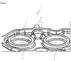
Figure 1 is a schematic view of the degassing system. -
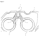
Figure 2 is another view of the degassing system. - The components in the figures are given reference numbers as follows:
- 1. Degassing system
- 2. Body
- 3. Slot
- 4. Slot opening
- 5. Delivery channel
- 6. Collection chamber
- 7. Collection channel
- 8. Discharge channel
- The degassing system (1) of the present invention comprises
- at least one body (2) which is in the form of a cover whose sides are higher than its middle part,
- at least two slots (3), each one of which can cover at least one part of a thermostat, and which preferably rise from the middle part of the body (2) in the same direction with the sides of the body (2),
- at least two slot openings (4), of which there is one provided in each slot (3), and which enable the gases accumulating in the slot (3) to be discharged from the slot (3),
- at least two delivery channels (5), of which there is one provided at each slot opening (4), and which enable to carry the gases arriving at the slot opening (4),
- at least one collection chamber (6) in which the gases carried by the delivery channels (5) accumulate,
- at least one collection channel (7), which is located on the collection chamber (6), and which enables the gases that may have accumulated in the body (2) to be discharged from the body (2) and the said gases to be taken into the collection chamber (6),
- at least one discharge channel (8) which enables the air accumulating in the collection chamber (6) to be discharged.
- The degassing system (1) of the present invention basically comprises at least one body (2) which is in the form of a cover whose sides are higher than its middle part, A tray which is flat in the middle having sides that curve upwards can be given as an example for the form of the body (2). There are at least two slots (3) on the flat part of the body (2), each one of which can cover at least one part of a thermostat. The said slots (3) are preferably circular in compliance with the upper section of the thermostats that will be disposed therein. The said circular shape forms a cylinder by rising from the middle part of the body (2) in the same direction with the sides of the body (2). There are at least two slot openings (4), of which there is one provided in each of the said slots (3) in order to enable the gases accumulating in the slot (3) to be discharged from the slot (3). The said slot openings (4) are connected to at least two delivery channels (5), of which there is one provided at each slot opening (4), and which enable to carry the gases arriving at the said slot openings (4). The degassing system (1) of the present invention comprises at least one collection chamber (6) in which the air carried by the delivery channels (5) accumulate. The degassing system (1) of the present invention also comprises at least one collection channel (7), which is located on the collection chamber (6), and which enables the gases that may have accumulated in the body (2) to be discharged from the body (2) and the said gases to be taken into the collection chamber (6). The collection chamber (6) comprises at least one discharge channel (8) which enables the air accumulating in the chamber to be discharged. The said discharge channel (8) enables the gases; which accumulate in the cooling system, to which the degassing system (1) of the present invention is connected; and which are collected by the degassing system (1); to be discharged from the said cooling system.
- In the preferred embodiment of the invention, the bodies of the thermostats installed in the degassing system (1) of the present invention are positioned at a higher point than the coolant provided in the cooling system to which the degassing system (1) is connected.
- In the preferred embodiment of the invention, the slot openings (4) enable degassing at the semi-open, fully-open and by-pass positions of the thermostats that are connected to the degassing system (1) of the present invention. In this embodiment, the collection channel (7) enables degassing at the semi-open and by-pass positions of the said thermostats. Thus degassing can be enabled for each position of the said thermostats.
- In the preferred embodiment of the invention, the slot openings (4) and the delivery channels (5) are circular having a diameter of 4 mm. In this embodiment, the discharge channel (8) is circular having a diameter of 1.5 mm. These values are given for the present embodiment; however these values can be different for different embodiments.
Claims (4)
- A degassing system (1) comprising- at least one body (2) which is in the form of a cover whose sides are higher than its middle part,- at least two slots (3), each one of which being adapted for covering at least one part of a thermostat, and which preferably rise from the middle part of the body (2) in the same direction with the sides of the body (2), and characterized by- at least two slot openings (4), of which there is one provided in each slot (3), and which enable the gases accumulating in the slot (3) to be discharged from the slot (3),- at least two delivery channels (5), of which there is one provided at each slot opening (4), and which enable to carry the gases arriving at the slot opening (4),- at least one collection chamber (6) in which the gases carried by the delivery channels (5) accumulate,- at least one collection channel (7), which is located on the collection chamber (6), and which enables the gases that may have accumulated in the body (2) to be discharged from the body (2) and the said gases to be taken into the collection chamber (6),- at least one discharge channel (8) which enables the air accumulating in the collection chamber (6) to be discharged.
- A degassing system (1) according to claim 1, characterized by the slot openings (4) which are circular having a diameter of 4 mm.
- A degassing system (1) according to any one of the preceding claims, characterized by the delivery channels (5) which are circular having a diameter of 4 mm.
- A degassing system (1) according to any one of the preceding claims, characterized by the discharge channel (8) which is circular having a diameter of 1.5 mm.
Applications Claiming Priority (2)
| Application Number | Priority Date | Filing Date | Title |
|---|---|---|---|
| TR201406100 | 2014-05-29 | ||
| PCT/TR2015/000221 WO2015183222A1 (en) | 2014-05-29 | 2015-05-28 | A degassing system |
Publications (2)
| Publication Number | Publication Date |
|---|---|
| EP3149304A1 EP3149304A1 (en) | 2017-04-05 |
| EP3149304B1 true EP3149304B1 (en) | 2018-04-25 |
Family
ID=53682774
Family Applications (1)
| Application Number | Title | Priority Date | Filing Date |
|---|---|---|---|
| EP15739360.4A Active EP3149304B1 (en) | 2014-05-29 | 2015-05-28 | A degassing system |
Country Status (6)
| Country | Link |
|---|---|
| EP (1) | EP3149304B1 (en) |
| CN (1) | CN106414942B (en) |
| BR (1) | BR112016028053B1 (en) |
| RU (1) | RU2649165C1 (en) |
| TR (1) | TR201616748T1 (en) |
| WO (1) | WO2015183222A1 (en) |
Families Citing this family (1)
| Publication number | Priority date | Publication date | Assignee | Title |
|---|---|---|---|---|
| CN110529280A (en) * | 2019-07-31 | 2019-12-03 | 上海中船三井造船柴油机有限公司 | The ventilative pipeline structure of diesel engine cylinder lid for ship/jacket-cooling water |
Family Cites Families (9)
| Publication number | Priority date | Publication date | Assignee | Title |
|---|---|---|---|---|
| DE2314301C3 (en) * | 1973-03-22 | 1978-07-20 | Bayerische Motoren Werke Ag, 8000 Muenchen | Uni-running cooling device for piston internal combustion engines |
| US4300718A (en) * | 1980-04-10 | 1981-11-17 | Ford Motor Company | Engine cooling system air venting arrangement |
| SU1373838A2 (en) * | 1986-06-13 | 1988-02-15 | Московский автомобильный завод им.И.А.Лихачева | Liquid-type cooling system of internal combustion engine |
| US5497734A (en) * | 1993-12-22 | 1996-03-12 | Nissan Motor Co., Ltd. | Cooling system for liquid-cooled engine |
| FR2739432B1 (en) * | 1995-09-29 | 1997-10-31 | Renault | THERMOSTATIC VALVE FOR INTERNAL COMBUSTION ENGINE |
| JP3819681B2 (en) * | 2000-07-03 | 2006-09-13 | 本田技研工業株式会社 | Water cooling engine cooling system |
| JP5672808B2 (en) * | 2010-07-20 | 2015-02-18 | トヨタ自動車株式会社 | Engine cooling system |
| JP2013068161A (en) * | 2011-09-22 | 2013-04-18 | Yamaha Motor Co Ltd | Saddle-type vehicle |
| US8967091B2 (en) * | 2011-12-14 | 2015-03-03 | Cummins Inc. | Thermostat housing which provides optimized coolant flow |
-
2015
- 2015-05-28 WO PCT/TR2015/000221 patent/WO2015183222A1/en not_active Ceased
- 2015-05-28 TR TR2016/16748T patent/TR201616748T1/en unknown
- 2015-05-28 CN CN201580028604.XA patent/CN106414942B/en active Active
- 2015-05-28 EP EP15739360.4A patent/EP3149304B1/en active Active
- 2015-05-28 BR BR112016028053-9A patent/BR112016028053B1/en active IP Right Grant
- 2015-05-28 RU RU2016151687A patent/RU2649165C1/en active
Non-Patent Citations (1)
| Title |
|---|
| None * |
Also Published As
| Publication number | Publication date |
|---|---|
| BR112016028053A2 (en) | 2018-06-19 |
| BR112016028053B1 (en) | 2021-11-03 |
| WO2015183222A1 (en) | 2015-12-03 |
| EP3149304A1 (en) | 2017-04-05 |
| CN106414942B (en) | 2019-04-12 |
| TR201616748T1 (en) | 2017-08-21 |
| RU2649165C1 (en) | 2018-03-30 |
| CN106414942A (en) | 2017-02-15 |
Similar Documents
| Publication | Publication Date | Title |
|---|---|---|
| JP5582133B2 (en) | Engine coolant circulation system | |
| US20150184576A1 (en) | Engine cooling system | |
| SE530802C2 (en) | Arrangement for heating oil in a gearbox | |
| US10060326B2 (en) | Cooling apparatus for internal combustion engine | |
| KR101953644B1 (en) | Multifunctional rotary valve module | |
| US8910471B2 (en) | Structure of exhaust pipe for exhaust heat recovery | |
| CN104210351A (en) | Powertrain cooling system with cooling and heating modes for heat exchangers | |
| WO2013011573A1 (en) | Engine cooling device | |
| US10480392B2 (en) | Engine cooling system having coolant temperature sensor | |
| RU2016140186A (en) | COOLING SYSTEM AND METHOD FOR INTERNAL COMBUSTION ENGINE AND THERMOSTAT UNIT FOR COOLING SYSTEM | |
| EP3109428A1 (en) | Exhaust heat recovery structure | |
| EP3246540B1 (en) | Dual catalytic converter exhaust-gas aftertreatment arrangement | |
| CN109653893B (en) | Cooling jacket for cylinder head | |
| KR102463203B1 (en) | Coolant control valve unit, and cooling system having this | |
| SE536826C2 (en) | Cooling | |
| WO2015183222A1 (en) | A degassing system | |
| US10215079B2 (en) | Thermostatic valve | |
| EP3066313B1 (en) | Method for operating an internal combustion engine | |
| JP6576702B2 (en) | Cooling water control device for vehicle internal combustion engine | |
| KR101307322B1 (en) | Automobile exhaust heat recovery device | |
| KR20190062803A (en) | Coolant control valve unit, and cooling system having this | |
| US20140230798A1 (en) | Internal combustion engine and method for operating an internal combustion engine | |
| JP6214447B2 (en) | Catalytic converter cooling mechanism | |
| KR102552021B1 (en) | Control method of cooling system | |
| JP6041001B2 (en) | Engine cooling system |
Legal Events
| Date | Code | Title | Description |
|---|---|---|---|
| PUAI | Public reference made under article 153(3) epc to a published international application that has entered the european phase |
Free format text: ORIGINAL CODE: 0009012 |
|
| 17P | Request for examination filed |
Effective date: 20161118 |
|
| AK | Designated contracting states |
Kind code of ref document: A1 Designated state(s): AL AT BE BG CH CY CZ DE DK EE ES FI FR GB GR HR HU IE IS IT LI LT LU LV MC MK MT NL NO PL PT RO RS SE SI SK SM TR |
|
| AX | Request for extension of the european patent |
Extension state: BA ME |
|
| RIN1 | Information on inventor provided before grant (corrected) |
Inventor name: TURGUT, IBRAHIM Inventor name: CEYHUN, OMER Inventor name: UNUVAR, BULENT Inventor name: BULUT, BARIS |
|
| RIN1 | Information on inventor provided before grant (corrected) |
Inventor name: CEYHUN, OMER Inventor name: UNUVAR, BULENT Inventor name: TURGUT, IBRAHIM Inventor name: BULUT, BARIS |
|
| DAV | Request for validation of the european patent (deleted) | ||
| DAX | Request for extension of the european patent (deleted) | ||
| REG | Reference to a national code |
Ref country code: DE Ref legal event code: R079 Ref document number: 602015010481 Country of ref document: DE Free format text: PREVIOUS MAIN CLASS: F01P0011020000 Ipc: F01P0007160000 |
|
| GRAP | Despatch of communication of intention to grant a patent |
Free format text: ORIGINAL CODE: EPIDOSNIGR1 |
|
| RIC1 | Information provided on ipc code assigned before grant |
Ipc: F01P 11/02 20060101ALI20171115BHEP Ipc: F01P 7/16 20060101AFI20171115BHEP |
|
| INTG | Intention to grant announced |
Effective date: 20171215 |
|
| GRAA | (expected) grant |
Free format text: ORIGINAL CODE: 0009210 |
|
| GRAS | Grant fee paid |
Free format text: ORIGINAL CODE: EPIDOSNIGR3 |
|
| AK | Designated contracting states |
Kind code of ref document: B1 Designated state(s): AL AT BE BG CH CY CZ DE DK EE ES FI FR GB GR HR HU IE IS IT LI LT LU LV MC MK MT NL NO PL PT RO RS SE SI SK SM TR |
|
| REG | Reference to a national code |
Ref country code: GB Ref legal event code: FG4D |
|
| REG | Reference to a national code |
Ref country code: CH Ref legal event code: EP |
|
| REG | Reference to a national code |
Ref country code: AT Ref legal event code: REF Ref document number: 993166 Country of ref document: AT Kind code of ref document: T Effective date: 20180515 |
|
| REG | Reference to a national code |
Ref country code: IE Ref legal event code: FG4D |
|
| REG | Reference to a national code |
Ref country code: DE Ref legal event code: R096 Ref document number: 602015010481 Country of ref document: DE |
|
| REG | Reference to a national code |
Ref country code: NL Ref legal event code: MP Effective date: 20180425 |
|
| REG | Reference to a national code |
Ref country code: LT Ref legal event code: MG4D |
|
| PG25 | Lapsed in a contracting state [announced via postgrant information from national office to epo] |
Ref country code: NL Free format text: LAPSE BECAUSE OF FAILURE TO SUBMIT A TRANSLATION OF THE DESCRIPTION OR TO PAY THE FEE WITHIN THE PRESCRIBED TIME-LIMIT Effective date: 20180425 |
|
| PG25 | Lapsed in a contracting state [announced via postgrant information from national office to epo] |
Ref country code: SE Free format text: LAPSE BECAUSE OF FAILURE TO SUBMIT A TRANSLATION OF THE DESCRIPTION OR TO PAY THE FEE WITHIN THE PRESCRIBED TIME-LIMIT Effective date: 20180425 Ref country code: LT Free format text: LAPSE BECAUSE OF FAILURE TO SUBMIT A TRANSLATION OF THE DESCRIPTION OR TO PAY THE FEE WITHIN THE PRESCRIBED TIME-LIMIT Effective date: 20180425 Ref country code: ES Free format text: LAPSE BECAUSE OF FAILURE TO SUBMIT A TRANSLATION OF THE DESCRIPTION OR TO PAY THE FEE WITHIN THE PRESCRIBED TIME-LIMIT Effective date: 20180425 Ref country code: BG Free format text: LAPSE BECAUSE OF FAILURE TO SUBMIT A TRANSLATION OF THE DESCRIPTION OR TO PAY THE FEE WITHIN THE PRESCRIBED TIME-LIMIT Effective date: 20180725 Ref country code: FI Free format text: LAPSE BECAUSE OF FAILURE TO SUBMIT A TRANSLATION OF THE DESCRIPTION OR TO PAY THE FEE WITHIN THE PRESCRIBED TIME-LIMIT Effective date: 20180425 Ref country code: NO Free format text: LAPSE BECAUSE OF FAILURE TO SUBMIT A TRANSLATION OF THE DESCRIPTION OR TO PAY THE FEE WITHIN THE PRESCRIBED TIME-LIMIT Effective date: 20180725 Ref country code: PL Free format text: LAPSE BECAUSE OF FAILURE TO SUBMIT A TRANSLATION OF THE DESCRIPTION OR TO PAY THE FEE WITHIN THE PRESCRIBED TIME-LIMIT Effective date: 20180425 |
|
| PG25 | Lapsed in a contracting state [announced via postgrant information from national office to epo] |
Ref country code: GR Free format text: LAPSE BECAUSE OF FAILURE TO SUBMIT A TRANSLATION OF THE DESCRIPTION OR TO PAY THE FEE WITHIN THE PRESCRIBED TIME-LIMIT Effective date: 20180726 Ref country code: LV Free format text: LAPSE BECAUSE OF FAILURE TO SUBMIT A TRANSLATION OF THE DESCRIPTION OR TO PAY THE FEE WITHIN THE PRESCRIBED TIME-LIMIT Effective date: 20180425 Ref country code: RS Free format text: LAPSE BECAUSE OF FAILURE TO SUBMIT A TRANSLATION OF THE DESCRIPTION OR TO PAY THE FEE WITHIN THE PRESCRIBED TIME-LIMIT Effective date: 20180425 Ref country code: HR Free format text: LAPSE BECAUSE OF FAILURE TO SUBMIT A TRANSLATION OF THE DESCRIPTION OR TO PAY THE FEE WITHIN THE PRESCRIBED TIME-LIMIT Effective date: 20180425 |
|
| REG | Reference to a national code |
Ref country code: CH Ref legal event code: PL |
|
| REG | Reference to a national code |
Ref country code: AT Ref legal event code: MK05 Ref document number: 993166 Country of ref document: AT Kind code of ref document: T Effective date: 20180425 |
|
| PG25 | Lapsed in a contracting state [announced via postgrant information from national office to epo] |
Ref country code: PT Free format text: LAPSE BECAUSE OF FAILURE TO SUBMIT A TRANSLATION OF THE DESCRIPTION OR TO PAY THE FEE WITHIN THE PRESCRIBED TIME-LIMIT Effective date: 20180827 |
|
| REG | Reference to a national code |
Ref country code: DE Ref legal event code: R097 Ref document number: 602015010481 Country of ref document: DE |
|
| REG | Reference to a national code |
Ref country code: BE Ref legal event code: MM Effective date: 20180531 |
|
| PG25 | Lapsed in a contracting state [announced via postgrant information from national office to epo] |
Ref country code: MC Free format text: LAPSE BECAUSE OF FAILURE TO SUBMIT A TRANSLATION OF THE DESCRIPTION OR TO PAY THE FEE WITHIN THE PRESCRIBED TIME-LIMIT Effective date: 20180425 Ref country code: CZ Free format text: LAPSE BECAUSE OF FAILURE TO SUBMIT A TRANSLATION OF THE DESCRIPTION OR TO PAY THE FEE WITHIN THE PRESCRIBED TIME-LIMIT Effective date: 20180425 Ref country code: RO Free format text: LAPSE BECAUSE OF FAILURE TO SUBMIT A TRANSLATION OF THE DESCRIPTION OR TO PAY THE FEE WITHIN THE PRESCRIBED TIME-LIMIT Effective date: 20180425 Ref country code: SK Free format text: LAPSE BECAUSE OF FAILURE TO SUBMIT A TRANSLATION OF THE DESCRIPTION OR TO PAY THE FEE WITHIN THE PRESCRIBED TIME-LIMIT Effective date: 20180425 Ref country code: EE Free format text: LAPSE BECAUSE OF FAILURE TO SUBMIT A TRANSLATION OF THE DESCRIPTION OR TO PAY THE FEE WITHIN THE PRESCRIBED TIME-LIMIT Effective date: 20180425 Ref country code: AT Free format text: LAPSE BECAUSE OF FAILURE TO SUBMIT A TRANSLATION OF THE DESCRIPTION OR TO PAY THE FEE WITHIN THE PRESCRIBED TIME-LIMIT Effective date: 20180425 Ref country code: DK Free format text: LAPSE BECAUSE OF FAILURE TO SUBMIT A TRANSLATION OF THE DESCRIPTION OR TO PAY THE FEE WITHIN THE PRESCRIBED TIME-LIMIT Effective date: 20180425 |
|
| REG | Reference to a national code |
Ref country code: IE Ref legal event code: MM4A |
|
| PG25 | Lapsed in a contracting state [announced via postgrant information from national office to epo] |
Ref country code: CH Free format text: LAPSE BECAUSE OF NON-PAYMENT OF DUE FEES Effective date: 20180531 Ref country code: LI Free format text: LAPSE BECAUSE OF NON-PAYMENT OF DUE FEES Effective date: 20180531 Ref country code: SM Free format text: LAPSE BECAUSE OF FAILURE TO SUBMIT A TRANSLATION OF THE DESCRIPTION OR TO PAY THE FEE WITHIN THE PRESCRIBED TIME-LIMIT Effective date: 20180425 Ref country code: IT Free format text: LAPSE BECAUSE OF FAILURE TO SUBMIT A TRANSLATION OF THE DESCRIPTION OR TO PAY THE FEE WITHIN THE PRESCRIBED TIME-LIMIT Effective date: 20180425 |
|
| PLBE | No opposition filed within time limit |
Free format text: ORIGINAL CODE: 0009261 |
|
| STAA | Information on the status of an ep patent application or granted ep patent |
Free format text: STATUS: NO OPPOSITION FILED WITHIN TIME LIMIT |
|
| PG25 | Lapsed in a contracting state [announced via postgrant information from national office to epo] |
Ref country code: LU Free format text: LAPSE BECAUSE OF NON-PAYMENT OF DUE FEES Effective date: 20180528 |
|
| 26N | No opposition filed |
Effective date: 20190128 |
|
| PG25 | Lapsed in a contracting state [announced via postgrant information from national office to epo] |
Ref country code: FR Free format text: LAPSE BECAUSE OF NON-PAYMENT OF DUE FEES Effective date: 20180625 Ref country code: IE Free format text: LAPSE BECAUSE OF NON-PAYMENT OF DUE FEES Effective date: 20180528 |
|
| PG25 | Lapsed in a contracting state [announced via postgrant information from national office to epo] |
Ref country code: SI Free format text: LAPSE BECAUSE OF FAILURE TO SUBMIT A TRANSLATION OF THE DESCRIPTION OR TO PAY THE FEE WITHIN THE PRESCRIBED TIME-LIMIT Effective date: 20180425 Ref country code: BE Free format text: LAPSE BECAUSE OF NON-PAYMENT OF DUE FEES Effective date: 20180531 |
|
| PG25 | Lapsed in a contracting state [announced via postgrant information from national office to epo] |
Ref country code: AL Free format text: LAPSE BECAUSE OF FAILURE TO SUBMIT A TRANSLATION OF THE DESCRIPTION OR TO PAY THE FEE WITHIN THE PRESCRIBED TIME-LIMIT Effective date: 20180425 |
|
| GBPC | Gb: european patent ceased through non-payment of renewal fee |
Effective date: 20190528 |
|
| PG25 | Lapsed in a contracting state [announced via postgrant information from national office to epo] |
Ref country code: MT Free format text: LAPSE BECAUSE OF NON-PAYMENT OF DUE FEES Effective date: 20180528 |
|
| PG25 | Lapsed in a contracting state [announced via postgrant information from national office to epo] |
Ref country code: TR Free format text: LAPSE BECAUSE OF FAILURE TO SUBMIT A TRANSLATION OF THE DESCRIPTION OR TO PAY THE FEE WITHIN THE PRESCRIBED TIME-LIMIT Effective date: 20180425 |
|
| PG25 | Lapsed in a contracting state [announced via postgrant information from national office to epo] |
Ref country code: GB Free format text: LAPSE BECAUSE OF NON-PAYMENT OF DUE FEES Effective date: 20190528 |
|
| PG25 | Lapsed in a contracting state [announced via postgrant information from national office to epo] |
Ref country code: CY Free format text: LAPSE BECAUSE OF FAILURE TO SUBMIT A TRANSLATION OF THE DESCRIPTION OR TO PAY THE FEE WITHIN THE PRESCRIBED TIME-LIMIT Effective date: 20180425 Ref country code: MK Free format text: LAPSE BECAUSE OF NON-PAYMENT OF DUE FEES Effective date: 20180425 Ref country code: HU Free format text: LAPSE BECAUSE OF FAILURE TO SUBMIT A TRANSLATION OF THE DESCRIPTION OR TO PAY THE FEE WITHIN THE PRESCRIBED TIME-LIMIT; INVALID AB INITIO Effective date: 20150528 |
|
| PG25 | Lapsed in a contracting state [announced via postgrant information from national office to epo] |
Ref country code: IS Free format text: LAPSE BECAUSE OF FAILURE TO SUBMIT A TRANSLATION OF THE DESCRIPTION OR TO PAY THE FEE WITHIN THE PRESCRIBED TIME-LIMIT Effective date: 20180825 |
|
| P01 | Opt-out of the competence of the unified patent court (upc) registered |
Effective date: 20230619 |
|
| PGFP | Annual fee paid to national office [announced via postgrant information from national office to epo] |
Ref country code: DE Payment date: 20250528 Year of fee payment: 11 |