EP3149267B1 - Fluid line exit block with dual metal-to-metal sealing - Google Patents
Fluid line exit block with dual metal-to-metal sealing Download PDFInfo
- Publication number
- EP3149267B1 EP3149267B1 EP15724494.8A EP15724494A EP3149267B1 EP 3149267 B1 EP3149267 B1 EP 3149267B1 EP 15724494 A EP15724494 A EP 15724494A EP 3149267 B1 EP3149267 B1 EP 3149267B1
- Authority
- EP
- European Patent Office
- Prior art keywords
- fluid line
- production device
- hydrocarbon production
- fluid
- block
- Prior art date
- Legal status (The legal status is an assumption and is not a legal conclusion. Google has not performed a legal analysis and makes no representation as to the accuracy of the status listed.)
- Active
Links
Images



Classifications
-
- E—FIXED CONSTRUCTIONS
- E21—EARTH OR ROCK DRILLING; MINING
- E21B—EARTH OR ROCK DRILLING; OBTAINING OIL, GAS, WATER, SOLUBLE OR MELTABLE MATERIALS OR A SLURRY OF MINERALS FROM WELLS
- E21B23/00—Apparatus for displacing, setting, locking, releasing or removing tools, packers or the like in boreholes or wells
- E21B23/14—Apparatus for displacing, setting, locking, releasing or removing tools, packers or the like in boreholes or wells for displacing a cable or a cable-operated tool, e.g. for logging or perforating operations in deviated wells
-
- E—FIXED CONSTRUCTIONS
- E21—EARTH OR ROCK DRILLING; MINING
- E21B—EARTH OR ROCK DRILLING; OBTAINING OIL, GAS, WATER, SOLUBLE OR MELTABLE MATERIALS OR A SLURRY OF MINERALS FROM WELLS
- E21B33/00—Sealing or packing boreholes or wells
- E21B33/02—Surface sealing or packing
- E21B33/03—Well heads; Setting-up thereof
- E21B33/035—Well heads; Setting-up thereof specially adapted for underwater installations
- E21B33/038—Connectors used on well heads, e.g. for connecting blow-out preventer and riser
-
- E—FIXED CONSTRUCTIONS
- E21—EARTH OR ROCK DRILLING; MINING
- E21B—EARTH OR ROCK DRILLING; OBTAINING OIL, GAS, WATER, SOLUBLE OR MELTABLE MATERIALS OR A SLURRY OF MINERALS FROM WELLS
- E21B33/00—Sealing or packing boreholes or wells
- E21B33/02—Surface sealing or packing
- E21B33/03—Well heads; Setting-up thereof
- E21B33/068—Well heads; Setting-up thereof having provision for introducing objects or fluids into, or removing objects from, wells
Definitions
- This invention relates in general to wellhead systems, and in particular, to a fluid line exit block seal arrangement of a wellhead system.
- hydrocarbon production devices such as a series of pipes, fittings, valves, and gauges
- a wellhead assembly to control the flow of fluids into the well.
- One, or a plurality of, penetrators or stems are typically installed in the hydrocarbon production device to allow downhole fluid lines, such as hydraulic control lines or fluid injection lines, to be routed through a sidewall of the hydrocarbon production device and down to a location below the wellhead.
- Wellhead assemblies are required to have an increasing number of downhole control lines and chemical injection lines.
- US 2013/168104 A1 discloses a well completion system which includes a wellhead, a control line assembly for use in completions that is mounted to the wellhead, and a tubing hanger.
- US 4181175 A discloses a control line exiting coupling which provides radial penetration of a control line through a tubing hanger wall, with a back seat for sealing should internal pressure create a packing leak on the penetrator.
- WO 2009/014797 A1 discloses a sealing system including an energizing member that simultaneously seats a plurality of sealing elements about a plurality of control lines, respectively.
- WO 2010/107987 A1 discloses a penetrator comprising a housing and a bulkhead positioned within the housing and configured to slide relative to the housing.
- Embodiments of the current disclosure can provide multiple fluid lines passing into a pressure containing portion of the wellhead assembly.
- Embodiments of the current disclosure provide control line exit blocks for mounting to a hydrocarbon production device that is suitable for high temperature and high pressure applications, such as for temperatures up to 176,7 Grad Celsius (350 °F) and pressures up to 1034 bar (15,000 psi).
- Dual metal to metal seals prevent pressure and fluids from escaping from the pressure containing portion and into the atmosphere between the control line exit block and hydrocarbon production device. The integrity of the dual metal to metal seals can be verified before installation of the control line exit block is completed.
- hydrocarbon production device 10 is shown, as an example, as a wellhead assembly. Hydrocarbon production device 10 could alternately be part of a Christmas tree or other choke, valve, adapter, or tubular assembly associated with a hydrocarbon well, that is subject to internal pressure. Termination block assemblies 12 are mounted to hydrocarbon production device 10. In embodiments of this disclosure, there can be one or more termination block assemblies 12, and as an example, there can be eight termination block assemblies 12, spaced radially around the outer diameter of hydrocarbon production device 10 at a generally similar axial location along hydrocarbon production device 10.
- Figure 3 is a section view of a portion of hydrocarbon production device 10 that does not show the central axis of hydrocarbon production device 10; but instead is a section view of fluid line 14 as it passes through sidewall passage 15 of hydrocarbon production device 10 and into termination block assembly 12.
- Fluid line 14 can be a control line, such as a hydraulic control line, a chemical injection line, or another type of fluid conduit used to convey fluids or communicate pressure through a sidewall of hydrocarbon production device 10.
- Fluid line 14 extends through the sidewall of hydrocarbon production device 10 by way of sidewall passage 15, from pressure containing portion 16 of hydrocarbon production device 10 to an outside surface of hydrocarbon production device 10.
- fluid line 14 extends into a pressurized annulus between tubular members located within the wellbore. In alternate embodiments of this disclosure, fluid line 14 extends into the pressurized main central bore of the hydrocarbon well, which is a non-annular space. In the example of Figure 2 , fluid line 14 extends into an annular space between hanger 18 and concentric tubular member 20 that is located radially inward from hanger 18. After passing out of a lower end of hanger 18, fluid line 14 can extend within the annular space between the outer wellhead member 22 and the tubular member 20. In certain embodiments, portions of fluid line 14 could be defined by passages formed within a sidewall of hanger 18. Tubular member 20 could be, for example, production tubing, casing, or unfinished pipe. Outer wellhead member 22 could be, for example, a multibowl wellhead.
- termination block assembly 12 includes fluid line block 28.
- fluid line block 28 is a generally square or rectangular block shaped member formed of metal.
- Fluid line block 28 has inner surface 30 that mates with corresponding surface 32 of hydrocarbon production device 10.
- Fluid line block 28 can be secured to hydrocarbon production device 10 with threaded members 34 or with other known fasteners.
- Fluid line block 28 has protruding member 36 that extends from inner surface 30.
- Protruding member 36 can be formed as an integral part of fluid line block 28 and has a cylindrical outer surface and block inner bore 38.
- Block inner bore 38 extends from an end of protruding member 36 to a junction with fluid passage 42, which is made up of a number of linear fluid passage segments 42a-42d, as will be further described below ( Figures 6 , 10 , 14 ).
- Termination block assembly 12 includes inlet port 40.
- Inlet port 40 is located at an outer surface of fluid line block 28, which as illustrated is on an opposite side of inner surface 30.
- Inlet port 40 can be used for injecting fluids, such as pressurized media for a control system or chemicals for injection into the hydrocarbon well.
- Inlet port connector 41 can be located in inlet port 40 to mate with the fluid delivery system used to provide the fluid to inlet port 40 and to seal inlet port 40 when no fluids are being supplied to inlet port 40.
- Inlet port connector 41 can be selected to withstand high pressure and high temperature, such as a temperature of up to 176,7 Grad Celsius (350 °F) and a pressure of up to 1034 bar (15,000 psi).
- fluid line block 28 can have one inlet port 40 ( Figures 6 , 13 ), and in alternate embodiments, fluid line block 28 can have more than one inlet port 40, such as, for example, three inlet ports 40 ( Figure 9 ).
- Fluid passage 42 is located within fluid line block 28 for allowing fluid communication between inlet port 40 and fluid line 14. Fluid passage 42 extends from block inner bore 38 to inlet port 40. When fluid line block 28 is secured to hydrocarbon production device 10, fluids can flow through inlet port 40, through fluid passage 42 to block inner bore 38, and pass into fluid line 14. Fluid passage 42 is made up of a number of linear fluid passage segments 42a-42d that intersect each other, where 42a is the fluid passage segment that is adjacent to inlet port 40 and the fluid passage segments are lettered consecutively from inlet port 40 to block inner bore 38.
- termination block assembly 12 can have second port 44 that provides a potential flow path from outside of fluid line block 28 to fluid line 14 and provides additional access to fluid passage 42.
- Second bore connector 46 can be located in second port 44 to seal second port 44 so that fluids from within fluid line block 28 cannot escape through second port 44 to the outside environment.
- Second bore connector 46 can be threaded into second port 44 and can be selected to withstand high pressure and high temperature, such as a temperature of up to 176,7 Grad Celsius (350 °F) and a pressure of up to 1034 bar (15,000 psi).
- second port 44 is located on a surface opposite protruding member 36 ( Figures 3-6 ).
- second port 44 is located on a different face of fluid line block 28 than protruding member 36 at an end of a portion of fluid passage 42 ( Figures 9 , 13 ).
- fluid line block has one second port 44 ( Figures 3-6 , 11-13 ).
- fluid line block has more than one second port 44, such as, for example, three second ports 44 ( Figures 7-9 ).
- Termination block assembly 12 includes needle valve assembly 48.
- Needle valve assembly 48 can affect the flow of fluids through fluid passage 42.
- Needle valve assembly 48 includes needle valve body 50 with a needle portion 52 and an external needle valve portion 53. Needle portion 52 moves axially along a segment of fluid passage 42 and has needle end 54 that mates with needle seat 56 formed within such segment of fluid passage 42. Needle seat 56 is defined by a change in inner diameter of fluid passage 42. Needle end 54 extends across fluid passage 42 at needle seat 56 to create a seal and prevent the flow of fluids past needle end 54. Needle seat 56 can be located proximate to a junction of fluid passage segments 42a-42d to prevent fluids from moving from one fluid passage segment 42a-42d to the next fluid passage segment 42a-42d.
- External needle valve portion 53 extends outside of fluid line block 28 and can be used to adjust the position of needle portion 52.
- fluid line block 28 has one needle valve assembly 48 ( Figure 6 ) and in other embodiments, fluid line block 28 has more than one needle valve assembly 48, such as, for example six needle valve assemblies 48 ( Figures 7 , 9-10 ) or two needle valve assemblies ( Figures 11 , 13-14 ).
- Termination block assembly 12 further includes primary seal 58.
- Primary seal 58 is located at the end of protruding member 36 and can be formed as an integral part of fluid line block 28.
- Primary seal 58 is a tubular shaped flexible end portion of protruding member 36.
- Primary seal 58 has outer diameter 62 that engages a sidewall passage surface of sidewall passage 15 of hydrocarbon production device 10, forming a metal to metal seal between fluid line block 28 and hydrocarbon production device 10.
- the inner diameter block inner bore 38 can be successively smaller away from the outer end of protruding member 36 so that the largest diameter of block inner bore 38 is at the open outer end of block inner bore 38.
- the wall thickness of primary seal 58 tapers so that it is smaller at the outer open end of block inner bore 38.
- the wall thickness of primary seal 58 deceases towards the outer open end of block inner bore 38 due to the increasing inner diameter of block inner bore 38.
- the shape of outer diameter 62 and of block inner bore 38 of primary seal 58 may be frusto-conical so that the wall thickness of primary seal 58 decreases towards the outer open end of block inner bore 38.
- Primary seal 58 is biased to be urged radially inward when fluid line block 28 is secured to hydrocarbon production device 10 so that primary seal 58 applies a radially outward force on sidewall passage 15.
- the inner diameter of the sidewall passage surface of sidewall passage 15 can be smaller than the relaxed diameter of outer diameter 62 so that when primary seal 58 is located within sidewall passage 15, primary seal 58 will be forced to flex inward to fit within sidewall passage 15.
- Termination block assembly 12 additionally includes secondary seal 64.
- Secondary seal 64 is a generally ring shaped member that circumscribes protruding member 36.
- Secondary seal 64 can be a metal seal ring with base 66 and leg 68 that extends radially outward from base 66.
- Leg 68 extends in a direction generally normal to base 66 in a direction opposite to protruding member 36.
- Leg 68 is located within, and in a relaxed state protrudes from, radial recess 69 on inner surface 30.
- One side of leg 68 engages inner surface 30 and the opposite side of leg 68 can engage corresponding surface 32 when fluid line block 28 is secured to hydrocarbon production device 10, forming a metal to metal seal between fluid line block 28 and hydrocarbon production device 10.
- Base 66 of secondary seal 64 is located within annular cavity 70.
- Primary seal 58 and secondary seal 64 define annular cavity 70 between fluid line block 28 and hydrocarbon production device 10.
- Annular cavity 70 is also defined in part by block annular groove 72 located on inner surface 30 and in part by apparatus annular groove 74 located on corresponding surface 32.
- the surface of base 66 from which leg 68 extends engages an inner diameter of annular cavity 70.
- the surface of base 66 on one side of leg 68 engages an inner diameter of block annular groove 72 and the surface of base 66 on an opposite side of leg 68 engages an inner diameter of apparatus annular groove 74.
- Termination block assembly 12 has a test port 76.
- Test port 76 is located at a surface of termination block assembly 12.
- Test passage 78 extends from test port 76 to block annular groove 72, providing a fluid path from test port 76 to annular cavity 70.
- a test port fitting 77 is located within test port 76 to seal test port 76 when test port 76 is not in use.
- fluid line 14 can be fed out of pressure containing portion 16 of hydrocarbon production device 10 through sidewall passage 15 to corresponding surface 32 at an outside of hydrocarbon production device 10.
- Anchor fitting 80 can be fitted over fluid line 14 to retain fluid line 14 in position relative to the hydrocarbon production device 10.
- Anchor fitting 80 is non-pressure containing.
- Anchor fitting 80 has an outer diameter that engages an inner diameter of sidewall passage 15 and an inner diameter that engages fluid line 14 so that fluid line 14 does not move radially inward along the axis of sidewall passage 15.
- Secondary seal 64 is placed over protruding member 36 so that secondary seal 64 circumscribes protruding member 36 and is spaced radially outward from protruding member 36. As discussed above, a portion of base 66 of secondary seal 64 is located within block annular groove 72 so that leg 68 sits partially within radial recess 69 on inner surface 30. The outer end of fluid line 14 can then be fed into the open outer end of protruding member 36 and along block inner bore 38 so that block inner bore 38 circumscribes fluid line 14. In an example of operation, as fluid line 14 is being fed through block inner bore 38, fluid line block 28 will be moved towards hydrocarbon production device 10 and primary seal 58 inserted into sidewall passage 15.
- the elasticity of the material used for forming primary seal 58 allows it to flex inward to fit within sidewall passage 15, creating a first metal to metal seal between outer diameter 62 of primary seal 58 and the inner surface of sidewall passage 15, thereby sealing between fluid line block 28 and hydrocarbon production device 10.
- Moving fluid line block 28 towards hydrocarbon production device 10 mates inner surface 30 of fluid line block 28 with corresponding surface 32 of hydrocarbon production device 10.
- Rotating threaded fasteners 34 secures fluid line block 28 to hydrocarbon production device 10.
- Mating inner surface 30 with corresponding surface 32 engages leg 68 of secondary seal 64 with both inner surface 30 of fluid line block 28 and corresponding surface 32 of hydrocarbon production device 10.
- Mating surfaces 30, 32 energizes secondary seal 64 to form a second metal to metal seal between fluid line block 28 and hydrocarbon production device 10.
- the axial height of leg 68 is greater than the axial height of radial recess 69, thus leg 68 will deform when energized to fill the radial length of radial recess 69.
- the integrity of primary and secondary seals 58, 64 can be tested by way of test port 76.
- pressure media As a pressure media is injected through test port 76 and into test passage 78, pressure media will enter annular cavity 70 and be in fluid communication with both primary seal 58 and secondary seal 64.
- the pressure of pressure media is monitored, monitoring can take place in the test passage 78, cavity 70, test port 76, or a combination of these. Detecting a decrease in pressure of pressure media can indicate that either primary or secondary seal 58, 64 is leaking. If pressure media escapes around secondary seal 64, it can be supposed that secondary seal 64 is leaking. If no pressure media escapes around secondary seal 64, and the pressure of the pressure media is decreasing, secondary seal 58 may be leaking.
- a fluid line connector 82 can be secured to the end of fluid line 14 and second port connector 46 can be installed in second port 44.
- control fluids, injection fluids, or other fluids used in conjunction with hydrocarbon production device 10 can be injected through inlet port 40.
- Needle valve assembly 48 can be used to provide pressure integrity by adjusting access of the fluids to fluid passage 42.
- needle end 54 can move axially along fluid passage segment 42b. When needle end 54 is mated with needle seat 56, fluid will not be able to travel along fluid passage segment 42b.
- fluid can travel from inlet port 40, through fluid passage segment 42a then through fluid passage segment 42b, and into block inner bore 38. From block inner bore 38, fluid can enter fluid line 14 and into pressure containing portion 16 of hydrocarbon production device 10.
- termination block assembly 12 has six needle valve assemblies 48'.
- Three needle valve assemblies 48a' can block fluid from traveling along fluid passage segment 42a' and three needle valve assemblies 48b' can block fluid from traveling along fluid passage segment 42c'.
- needle end 54 of each of the needle valve assemblies 48' is spaced apart from needle seat 56, fluid can travel from one of three inlet ports 40, through one of three corresponding fluid passage segments 42a' and fluid passage segments 42b', into a single fluid passage segment 42c' and then into single block inner bore 38. From block inner bore 38, fluid can enter fluid line 14 and into pressure containing portion 16 of hydrocarbon production device 10.
- termination block assembly 12 has two needle valve assemblies 48". Needle valve assembly 48a” can block fluid from traveling along fluid passage segment 42a" and needle valve assembly 48b” can block fluid from traveling along fluid passage segment 42c". When needle end 54 of each of the needle valve assemblies 48" is spaced apart from needle seat 56, fluid can travel from inlet port 40, through fluid passage segment 42a", fluid passage segment 42b", and fluid passage segment 42c" and then into block inner bore 38. From block inner bore 38, fluid can enter fluid line 14 and into pressure containing portion 16 of hydrocarbon production device 10.
- primary seal 58 and secondary seal 64 prevent pressure and fluids from pressure containing portion 16 of hydrocarbon production device 10 from being discharged to the environment.
- Primary seal 58 and secondary seal 64 are redundant seals, both sealing between fluid line block 28 and hydrocarbon production device 10, and providing dual metal to metal sealing capabilities suitable for high pressure and high temperature applications.
Landscapes
- Life Sciences & Earth Sciences (AREA)
- Engineering & Computer Science (AREA)
- Geology (AREA)
- Mining & Mineral Resources (AREA)
- Physics & Mathematics (AREA)
- Environmental & Geological Engineering (AREA)
- Fluid Mechanics (AREA)
- General Life Sciences & Earth Sciences (AREA)
- Geochemistry & Mineralogy (AREA)
- Production Of Liquid Hydrocarbon Mixture For Refining Petroleum (AREA)
Description
- This invention relates in general to wellhead systems, and in particular, to a fluid line exit block seal arrangement of a wellhead system.
- For many surface and subsea oil and gas wells, hydrocarbon production devices, such as a series of pipes, fittings, valves, and gauges, are used on a wellhead as part of a wellhead assembly to control the flow of fluids into the well. One, or a plurality of, penetrators or stems are typically installed in the hydrocarbon production device to allow downhole fluid lines, such as hydraulic control lines or fluid injection lines, to be routed through a sidewall of the hydrocarbon production device and down to a location below the wellhead. Wellhead assemblies are required to have an increasing number of downhole control lines and chemical injection lines.
US 2013/168104 A1 discloses a well completion system which includes a wellhead, a control line assembly for use in completions that is mounted to the wellhead, and a tubing hanger.
US 4181175 A discloses a control line exiting coupling which provides radial penetration of a control line through a tubing hanger wall, with a back seat for sealing should internal pressure create a packing leak on the penetrator.
WO 2009/014797 A1 discloses a sealing system including an energizing member that simultaneously seats a plurality of sealing elements about a plurality of control lines, respectively.
WO 2010/107987 A1 discloses a penetrator comprising a housing and a bulkhead positioned within the housing and configured to slide relative to the housing. - Methods and systems of embodiments of the current disclosure can provide multiple fluid lines passing into a pressure containing portion of the wellhead assembly. Embodiments of the current disclosure provide control line exit blocks for mounting to a hydrocarbon production device that is suitable for high temperature and high pressure applications, such as for temperatures up to 176,7 Grad Celsius (350 °F) and pressures up to 1034 bar (15,000 psi). Dual metal to metal seals prevent pressure and fluids from escaping from the pressure containing portion and into the atmosphere between the control line exit block and hydrocarbon production device. The integrity of the dual metal to metal seals can be verified before installation of the control line exit block is completed.
- The invention is defined by the claims.
- Some of the features and benefits of the present invention having been stated, others will become apparent as the description proceeds when taken in conjunction with the accompanying drawings, in which:
-
Figure 1 is a perspective view of an example of a hydrocarbon production device with a termination block assembly in accordance with an embodiment of this disclosure. -
Figure 2 is a perspective view of the hydrocarbon production device ofFigure 1 , with an external multibowl portion not shown, in order to better visualize the fluid lines. -
Figure 3 is a section view of the hydrocarbon production device ofFigure 1 , showing a control line extending out of the hydrocarbon production device and to the termination block assembly. -
Figure 4 is a detail sectional view of a portion of the hydrocarbon production device and the termination block assembly ofFigure 3 . -
Figure 5 is a section view of the termination block assembly ofFigure 3 . -
Figure 6 is another section view of the termination block assembly ofFigure 3 . -
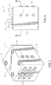
Figure 7 is a perspective view of an alternate termination block assembly in accordance with an embodiment of this disclosure. -
Figure 8 is a side elevation view of the termination block assembly ofFigure 7 . -
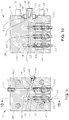
Figure 9 is a section view of the termination block assembly ofFigure 7 , viewed along the section line indicated inFigure 8 . -
Figure 10 is a section view of the termination block assembly ofFigure 7 , viewed along the section line indicated inFigure 9 . -
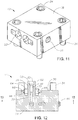
Figure 11 is a perspective view of an alternate termination block assembly in accordance with an embodiment of this disclosure. -
Figure 12 is a section view of the termination block assembly ofFigure 11 , viewed along the section line indicated inFigure 14 . -
Figure 13 is a section view of the termination block assembly ofFigure 11 , viewed along the section line indicated inFigure 12 . -
Figure 14 is a section view of the termination block assembly ofFigure 11 , viewed along the section line indicated inFigure 13 . - The methods and systems of the present disclosure will now be described more fully hereinafter with reference to the accompanying drawings in which embodiments are shown. The methods and systems of the present disclosure may be in many different forms and should not be construed as limited to the illustrated embodiments set forth herein; rather, these embodiments are provided so that this disclosure will be thorough and complete, and will fully convey its scope to those skilled in the art. Like numbers refer to like elements throughout.
- In the drawings and specification, there have been disclosed illustrative embodiments and, although specific terms are employed, they are used in a generic and descriptive sense only and not for the purpose of limitation.
- Referring to
Figure 1 ,hydrocarbon production device 10 is shown, as an example, as a wellhead assembly.Hydrocarbon production device 10 could alternately be part of a Christmas tree or other choke, valve, adapter, or tubular assembly associated with a hydrocarbon well, that is subject to internal pressure.Termination block assemblies 12 are mounted tohydrocarbon production device 10. In embodiments of this disclosure, there can be one or moretermination block assemblies 12, and as an example, there can be eighttermination block assemblies 12, spaced radially around the outer diameter ofhydrocarbon production device 10 at a generally similar axial location alonghydrocarbon production device 10. -
Figure 3 is a section view of a portion ofhydrocarbon production device 10 that does not show the central axis ofhydrocarbon production device 10; but instead is a section view offluid line 14 as it passes throughsidewall passage 15 ofhydrocarbon production device 10 and intotermination block assembly 12.Fluid line 14 can be a control line, such as a hydraulic control line, a chemical injection line, or another type of fluid conduit used to convey fluids or communicate pressure through a sidewall ofhydrocarbon production device 10.Fluid line 14 extends through the sidewall ofhydrocarbon production device 10 by way ofsidewall passage 15, frompressure containing portion 16 ofhydrocarbon production device 10 to an outside surface ofhydrocarbon production device 10. - In certain embodiments of this disclosure,
fluid line 14 extends into a pressurized annulus between tubular members located within the wellbore. In alternate embodiments of this disclosure,fluid line 14 extends into the pressurized main central bore of the hydrocarbon well, which is a non-annular space. In the example ofFigure 2 ,fluid line 14 extends into an annular space betweenhanger 18 and concentrictubular member 20 that is located radially inward fromhanger 18. After passing out of a lower end ofhanger 18,fluid line 14 can extend within the annular space between theouter wellhead member 22 and thetubular member 20. In certain embodiments, portions offluid line 14 could be defined by passages formed within a sidewall ofhanger 18.Tubular member 20 could be, for example, production tubing, casing, or unfinished pipe.Outer wellhead member 22 could be, for example, a multibowl wellhead. - Looking at
Figures 1-14 ,termination block assembly 12 includesfluid line block 28. In the non-limiting illustrated examples,fluid line block 28 is a generally square or rectangular block shaped member formed of metal.Fluid line block 28 hasinner surface 30 that mates withcorresponding surface 32 ofhydrocarbon production device 10.Fluid line block 28 can be secured tohydrocarbon production device 10 with threadedmembers 34 or with other known fasteners.Fluid line block 28 has protrudingmember 36 that extends frominner surface 30. Protrudingmember 36 can be formed as an integral part offluid line block 28 and has a cylindrical outer surface and blockinner bore 38. Blockinner bore 38 extends from an end of protrudingmember 36 to a junction withfluid passage 42, which is made up of a number of linearfluid passage segments 42a-42d, as will be further described below (Figures 6 ,10 ,14 ). -
Termination block assembly 12 includesinlet port 40.Inlet port 40 is located at an outer surface offluid line block 28, which as illustrated is on an opposite side ofinner surface 30.Inlet port 40 can be used for injecting fluids, such as pressurized media for a control system or chemicals for injection into the hydrocarbon well.Inlet port connector 41 can be located ininlet port 40 to mate with the fluid delivery system used to provide the fluid toinlet port 40 and to sealinlet port 40 when no fluids are being supplied toinlet port 40.Inlet port connector 41 can be selected to withstand high pressure and high temperature, such as a temperature of up to 176,7 Grad Celsius (350 °F) and a pressure of up to 1034 bar (15,000 psi). In embodiments of this disclosure,fluid line block 28 can have one inlet port 40 (Figures 6 ,13 ), and in alternate embodiments,fluid line block 28 can have more than oneinlet port 40, such as, for example, three inlet ports 40 (Figure 9 ). -
Fluid passage 42 is located withinfluid line block 28 for allowing fluid communication betweeninlet port 40 andfluid line 14.Fluid passage 42 extends from block inner bore 38 toinlet port 40. Whenfluid line block 28 is secured tohydrocarbon production device 10, fluids can flow throughinlet port 40, throughfluid passage 42 to blockinner bore 38, and pass intofluid line 14.Fluid passage 42 is made up of a number of linearfluid passage segments 42a-42d that intersect each other, where 42a is the fluid passage segment that is adjacent toinlet port 40 and the fluid passage segments are lettered consecutively frominlet port 40 to blockinner bore 38. - In addition to
inlet port 40,termination block assembly 12 can havesecond port 44 that provides a potential flow path from outside offluid line block 28 tofluid line 14 and provides additional access tofluid passage 42.Second bore connector 46 can be located insecond port 44 to sealsecond port 44 so that fluids from withinfluid line block 28 cannot escape throughsecond port 44 to the outside environment.Second bore connector 46 can be threaded intosecond port 44 and can be selected to withstand high pressure and high temperature, such as a temperature of up to 176,7 Grad Celsius (350 °F) and a pressure of up to 1034 bar (15,000 psi). In embodiments of this disclosure,second port 44 is located on a surface opposite protruding member 36 (Figures 3-6 ). In alternate embodiments,second port 44 is located on a different face offluid line block 28 than protrudingmember 36 at an end of a portion of fluid passage 42 (Figures 9 ,13 ). In embodiments of this disclosure, fluid line block has one second port 44 (Figures 3-6 ,11-13 ). In alternate embodiments fluid line block has more than onesecond port 44, such as, for example, three second ports 44 (Figures 7-9 ). -
Termination block assembly 12 includesneedle valve assembly 48.Needle valve assembly 48 can affect the flow of fluids throughfluid passage 42.Needle valve assembly 48 includesneedle valve body 50 with aneedle portion 52 and an externalneedle valve portion 53.Needle portion 52 moves axially along a segment offluid passage 42 and hasneedle end 54 that mates withneedle seat 56 formed within such segment offluid passage 42.Needle seat 56 is defined by a change in inner diameter offluid passage 42.Needle end 54 extends acrossfluid passage 42 atneedle seat 56 to create a seal and prevent the flow of fluidspast needle end 54.Needle seat 56 can be located proximate to a junction offluid passage segments 42a-42d to prevent fluids from moving from onefluid passage segment 42a-42d to the nextfluid passage segment 42a-42d. Externalneedle valve portion 53 extends outside offluid line block 28 and can be used to adjust the position ofneedle portion 52. In certain embodiments of this disclosure,fluid line block 28 has one needle valve assembly 48 (Figure 6 ) and in other embodiments,fluid line block 28 has more than oneneedle valve assembly 48, such as, for example six needle valve assemblies 48 (Figures 7 ,9-10 ) or two needle valve assemblies (Figures 11 ,13-14 ). -
Termination block assembly 12 further includesprimary seal 58.Primary seal 58 is located at the end of protrudingmember 36 and can be formed as an integral part offluid line block 28.Primary seal 58 is a tubular shaped flexible end portion of protrudingmember 36.Primary seal 58 hasouter diameter 62 that engages a sidewall passage surface ofsidewall passage 15 ofhydrocarbon production device 10, forming a metal to metal seal betweenfluid line block 28 andhydrocarbon production device 10. The inner diameter block inner bore 38 can be successively smaller away from the outer end of protrudingmember 36 so that the largest diameter of block inner bore 38 is at the open outer end of blockinner bore 38. The wall thickness ofprimary seal 58 tapers so that it is smaller at the outer open end of blockinner bore 38. The wall thickness ofprimary seal 58 deceases towards the outer open end of block inner bore 38 due to the increasing inner diameter of blockinner bore 38. In addition, the shape ofouter diameter 62 and of block inner bore 38 ofprimary seal 58 may be frusto-conical so that the wall thickness ofprimary seal 58 decreases towards the outer open end of blockinner bore 38. Whenfluid line block 28 is secured tohydrocarbon production device 10, blockinner bore 38 circumscribes a portion offluid line 14, which extends fromhydrocarbon production device 10. -
Primary seal 58 is biased to be urged radially inward whenfluid line block 28 is secured tohydrocarbon production device 10 so thatprimary seal 58 applies a radially outward force onsidewall passage 15. For example, the inner diameter of the sidewall passage surface ofsidewall passage 15 can be smaller than the relaxed diameter ofouter diameter 62 so that whenprimary seal 58 is located withinsidewall passage 15,primary seal 58 will be forced to flex inward to fit withinsidewall passage 15. This biasesprimary seal 58 so that it applies a radially outward force along the inner diameter of the sidewall passage surface ofsidewall passage 15, creating a seal betweenouter diameter 62 ofprimary seal 58 and the inner diameter of the sidewall passage surface ofsidewall passage 15. In this way, a first metal to metal seal is formed betweenfluid line block 28 andhydrocarbon production device 10 withprimary seal 58. -
Termination block assembly 12 additionally includessecondary seal 64.Secondary seal 64 is a generally ring shaped member that circumscribes protrudingmember 36.Secondary seal 64 can be a metal seal ring withbase 66 andleg 68 that extends radially outward frombase 66.Leg 68 extends in a direction generally normal tobase 66 in a direction opposite to protrudingmember 36.Leg 68 is located within, and in a relaxed state protrudes from,radial recess 69 oninner surface 30. One side ofleg 68 engagesinner surface 30 and the opposite side ofleg 68 can engage correspondingsurface 32 whenfluid line block 28 is secured tohydrocarbon production device 10, forming a metal to metal seal betweenfluid line block 28 andhydrocarbon production device 10.Base 66 ofsecondary seal 64 is located withinannular cavity 70.Primary seal 58 andsecondary seal 64 defineannular cavity 70 betweenfluid line block 28 andhydrocarbon production device 10.Annular cavity 70 is also defined in part by blockannular groove 72 located oninner surface 30 and in part by apparatusannular groove 74 located on correspondingsurface 32. The surface ofbase 66 from whichleg 68 extends engages an inner diameter ofannular cavity 70. The surface ofbase 66 on one side ofleg 68 engages an inner diameter of blockannular groove 72 and the surface ofbase 66 on an opposite side ofleg 68 engages an inner diameter of apparatusannular groove 74. -
Termination block assembly 12 has atest port 76.Test port 76 is located at a surface oftermination block assembly 12.Test passage 78 extends fromtest port 76 to blockannular groove 72, providing a fluid path fromtest port 76 toannular cavity 70. A test port fitting 77 is located withintest port 76 to sealtest port 76 whentest port 76 is not in use. - In an example of operation, to terminate
fluid line 14 athydrocarbon production device 10,fluid line 14 can be fed out ofpressure containing portion 16 ofhydrocarbon production device 10 throughsidewall passage 15 to correspondingsurface 32 at an outside ofhydrocarbon production device 10. Anchor fitting 80 can be fitted overfluid line 14 to retainfluid line 14 in position relative to thehydrocarbon production device 10. Anchor fitting 80 is non-pressure containing. Anchor fitting 80 has an outer diameter that engages an inner diameter ofsidewall passage 15 and an inner diameter that engagesfluid line 14 so thatfluid line 14 does not move radially inward along the axis ofsidewall passage 15. -
Secondary seal 64 is placed over protrudingmember 36 so thatsecondary seal 64circumscribes protruding member 36 and is spaced radially outward from protrudingmember 36. As discussed above, a portion ofbase 66 ofsecondary seal 64 is located within blockannular groove 72 so thatleg 68 sits partially withinradial recess 69 oninner surface 30. The outer end offluid line 14 can then be fed into the open outer end of protrudingmember 36 and along block inner bore 38 so that block inner bore 38 circumscribesfluid line 14. In an example of operation, asfluid line 14 is being fed through block inner bore 38,fluid line block 28 will be moved towardshydrocarbon production device 10 andprimary seal 58 inserted intosidewall passage 15. The elasticity of the material used for formingprimary seal 58 allows it to flex inward to fit withinsidewall passage 15, creating a first metal to metal seal betweenouter diameter 62 ofprimary seal 58 and the inner surface ofsidewall passage 15, thereby sealing betweenfluid line block 28 andhydrocarbon production device 10. - Moving
fluid line block 28 towardshydrocarbon production device 10 matesinner surface 30 offluid line block 28 with correspondingsurface 32 ofhydrocarbon production device 10. Rotating threadedfasteners 34 securesfluid line block 28 tohydrocarbon production device 10. Matinginner surface 30 with correspondingsurface 32, engagesleg 68 ofsecondary seal 64 with bothinner surface 30 offluid line block 28 and correspondingsurface 32 ofhydrocarbon production device 10. Mating surfaces 30, 32 energizessecondary seal 64 to form a second metal to metal seal betweenfluid line block 28 andhydrocarbon production device 10. In the illustrated examples the axial height ofleg 68 is greater than the axial height ofradial recess 69, thusleg 68 will deform when energized to fill the radial length ofradial recess 69. - The integrity of primary and
secondary seals test port 76. As a pressure media is injected throughtest port 76 and intotest passage 78, pressure media will enterannular cavity 70 and be in fluid communication with bothprimary seal 58 andsecondary seal 64. In an example of operation, the pressure of pressure media is monitored, monitoring can take place in thetest passage 78,cavity 70,test port 76, or a combination of these. Detecting a decrease in pressure of pressure media can indicate that either primary orsecondary seal secondary seal 64, it can be supposed thatsecondary seal 64 is leaking. If no pressure media escapes aroundsecondary seal 64, and the pressure of the pressure media is decreasing,secondary seal 58 may be leaking. - Looking at
Figures 3-6 , afluid line connector 82 can be secured to the end offluid line 14 andsecond port connector 46 can be installed insecond port 44. During use offluid line 14, control fluids, injection fluids, or other fluids used in conjunction withhydrocarbon production device 10 can be injected throughinlet port 40.Needle valve assembly 48 can be used to provide pressure integrity by adjusting access of the fluids tofluid passage 42. In the embodiment ofFigure 6 ,needle end 54 can move axially alongfluid passage segment 42b. Whenneedle end 54 is mated withneedle seat 56, fluid will not be able to travel alongfluid passage segment 42b. Whenneedle end 54 is spaced apart fromneedle seat 56, fluid can travel frominlet port 40, throughfluid passage segment 42a then throughfluid passage segment 42b, and into block inner bore 38. From block inner bore 38, fluid can enterfluid line 14 and intopressure containing portion 16 ofhydrocarbon production device 10. - Turning to
Figures 7-10 ,termination block assembly 12 has sixneedle valve assemblies 48'. Three needle valve assemblies 48a' can block fluid from traveling alongfluid passage segment 42a' and threeneedle valve assemblies 48b' can block fluid from traveling alongfluid passage segment 42c'. When needle end 54 of each of theneedle valve assemblies 48' is spaced apart fromneedle seat 56, fluid can travel from one of threeinlet ports 40, through one of three correspondingfluid passage segments 42a' andfluid passage segments 42b', into a singlefluid passage segment 42c' and then into single block inner bore 38. From block inner bore 38, fluid can enterfluid line 14 and intopressure containing portion 16 ofhydrocarbon production device 10. - Turning to
Figures 11-14 ,termination block assembly 12 has twoneedle valve assemblies 48". Needle valve assembly 48a" can block fluid from traveling alongfluid passage segment 42a" andneedle valve assembly 48b" can block fluid from traveling alongfluid passage segment 42c". When needle end 54 of each of theneedle valve assemblies 48" is spaced apart fromneedle seat 56, fluid can travel frominlet port 40, throughfluid passage segment 42a",fluid passage segment 42b", andfluid passage segment 42c" and then into block inner bore 38. From block inner bore 38, fluid can enterfluid line 14 and intopressure containing portion 16 ofhydrocarbon production device 10. - Returning again to
Figures 2-14 , in each of the embodiments of the current disclosure,primary seal 58 andsecondary seal 64 prevent pressure and fluids frompressure containing portion 16 ofhydrocarbon production device 10 from being discharged to the environment.Primary seal 58 andsecondary seal 64 are redundant seals, both sealing betweenfluid line block 28 andhydrocarbon production device 10, and providing dual metal to metal sealing capabilities suitable for high pressure and high temperature applications. - The terms "vertical", "horizontal", "upward", "downward", "above", and "below" are used herein only for convenience because elements of embodiments of this disclosure may be utilized in various positions.
- The system and method described herein, therefore, are well adapted to carry out the objects and attain the ends and advantages mentioned, as well as others inherent therein. While a presently preferred embodiment of the system and method has been given for purposes of disclosure, numerous changes exist in the details of procedures for accomplishing the desired results.
Claims (9)
- A termination block assembly for fluidly coupling a fluid line (14) at a hydrocarbon production device (10), the termination block assembly comprising:a fluid line block (28) with an inner surface (30) adapted to be selectively mated to a corresponding surface (32) of the hydrocarbon production device (10), the fluid line block (28) having a protruding member (36) extending from the inner surface (30);a primary seal (58) located at an end of the protruding member (36), the primary seal (58) having an inner diameter suitable for selectively circumscribing the fluid line (14) extending from the hydrocarbon production device (10), and an outer diameter suitable for selectively engaging a sidewall passage surface of the hydrocarbon production device (10) and sealing between the fluid line block (28) and the hydrocarbon production device (10);a secondary seal (64) circumscribing the protruding member (36), engaging both the inner surface (30) of the fluid line block (28) and the corresponding surface (32) of the hydrocarbon production device (10) and sealing between the fluid line block (28) and the hydrocarbon production device (10), characterized in that the primary seal and the secondary seal define an annular cavity (70) between the fluid line block and the hydrocarbon production device; and in that a test port (76) is in fluid communication with the annular cavity for monitoring pressure within the annular cavity.
- The termination block assembly of claim 1, wherein the primary seal (58) includes a flexible end portion of the protruding member (36) selectively forming a metal to metal seal with the sidewall passage surface of the hydrocarbon production device (10).
- The termination block assembly of claim 1 or 2, wherein the secondary seal (64) is a metal seal ring with a base (66) and a leg (68) that extends from the base (66) and engages both the inner surface (30) of the fluid line block (28) and the corresponding surface (32) of the hydrocarbon production device (10).
- The termination block assembly of any of claims 1-3, wherein the fluid line block (28) has the test port (76) and wherein the primary seal (58) and the secondary seal (64) are testable with the test port (76).
- The termination block assembly of any of claims 1-4, further comprising an anchor fitting (80) adapted to be attached to the fluid line (14) retaining the fluid line (14) in position relative to the hydrocarbon production device (10).
- The termination block assembly of any of claims claim 1-5, wherein the fluid line block (28) includes an inlet port (40) and a fluid passage (42) between the inlet port (40) and the fluid line (14).
- The termination block assembly of claim 6, wherein the fluid line block (28) includes at least one needle valve assembly (48) with a needle end (54) that engages a needle seat (56) within the fluid passage (42), selectively sealing the fluid passage (42).
- The termination block assembly of claim 6, wherein the inlet port (40) is in fluid communication with an annulus between tubular members (18, 20) of a wellbore.
- The termination block assembly of claim 6, wherein the inlet port (40) is in fluid communication with a non-annular bore of a hydrocarbon well.
Applications Claiming Priority (2)
| Application Number | Priority Date | Filing Date | Title |
|---|---|---|---|
| US14/289,503 US20150345243A1 (en) | 2014-05-28 | 2014-05-28 | Fluid Line Exit Block With Dual Metal-to-Metal Sealing |
| PCT/US2015/030678 WO2015183562A1 (en) | 2014-05-28 | 2015-05-14 | Fluid line exit block with dual metal-to-metal sealing |
Publications (2)
| Publication Number | Publication Date |
|---|---|
| EP3149267A1 EP3149267A1 (en) | 2017-04-05 |
| EP3149267B1 true EP3149267B1 (en) | 2019-03-27 |
Family
ID=53264831
Family Applications (1)
| Application Number | Title | Priority Date | Filing Date |
|---|---|---|---|
| EP15724494.8A Active EP3149267B1 (en) | 2014-05-28 | 2015-05-14 | Fluid line exit block with dual metal-to-metal sealing |
Country Status (3)
| Country | Link |
|---|---|
| US (1) | US20150345243A1 (en) |
| EP (1) | EP3149267B1 (en) |
| WO (1) | WO2015183562A1 (en) |
Families Citing this family (3)
| Publication number | Priority date | Publication date | Assignee | Title |
|---|---|---|---|---|
| GB2590583B (en) * | 2016-03-04 | 2021-09-22 | Aker Solutions As | Subsea well equipment landing indicator and locking indicator |
| US10480272B2 (en) * | 2016-07-08 | 2019-11-19 | Cameron International Corporation | Isolation flange assembly |
| GB2579242C (en) * | 2018-11-27 | 2024-08-21 | Siemens Energy Global Gmbh & Co Kg | Seal assembly and method of testing |
Family Cites Families (10)
| Publication number | Priority date | Publication date | Assignee | Title |
|---|---|---|---|---|
| US4181175A (en) * | 1978-09-27 | 1980-01-01 | Combustion Engineering, Inc. | Control line exiting coupling |
| US4476897A (en) * | 1979-10-24 | 1984-10-16 | Smith International, Inc. | Flowline connector seal |
| US6050338A (en) * | 1998-06-16 | 2000-04-18 | Dril-Quip, Inc. | Subsea wellhead apparatus |
| US6598680B2 (en) * | 2001-06-25 | 2003-07-29 | Dril-Quip, Inc. | Subsea wellhead equipment |
| US20050067167A1 (en) * | 2003-09-25 | 2005-03-31 | Hall Douglas D. | Radial penetrator assembly and method |
| GB2486109B (en) * | 2007-07-25 | 2012-07-18 | Cameron Int Corp | System and method to seal multiple control lines |
| US8235125B2 (en) * | 2009-01-05 | 2012-08-07 | Vetco Gray Inc. | System and method for terminating tubing |
| AU2010226562B2 (en) * | 2009-03-18 | 2014-11-20 | Aker Solutions Inc. | Locking penetrator |
| US9103182B2 (en) * | 2011-12-28 | 2015-08-11 | Vetco Gray Inc. | Metal-to-metal sealing arrangement for control line and method of using same |
| US9976377B2 (en) * | 2014-12-01 | 2018-05-22 | Cameron International Corporation | Control line termination assembly |
-
2014
- 2014-05-28 US US14/289,503 patent/US20150345243A1/en not_active Abandoned
-
2015
- 2015-05-14 EP EP15724494.8A patent/EP3149267B1/en active Active
- 2015-05-14 WO PCT/US2015/030678 patent/WO2015183562A1/en not_active Ceased
Non-Patent Citations (1)
| Title |
|---|
| None * |
Also Published As
| Publication number | Publication date |
|---|---|
| US20150345243A1 (en) | 2015-12-03 |
| WO2015183562A1 (en) | 2015-12-03 |
| EP3149267A1 (en) | 2017-04-05 |
Similar Documents
| Publication | Publication Date | Title |
|---|---|---|
| EP2464813B1 (en) | Dual barrier plug system for a wellhead | |
| US9103182B2 (en) | Metal-to-metal sealing arrangement for control line and method of using same | |
| EP3495604B1 (en) | Subsea isolation sleeve system | |
| US10513921B2 (en) | Control line retainer for a downhole tool | |
| EP2625373B1 (en) | Subsea wellhead | |
| US20150345243A1 (en) | Fluid Line Exit Block With Dual Metal-to-Metal Sealing | |
| EP3921507B1 (en) | One-piece production/annulus bore stab with integral flow paths | |
| EP3701117B1 (en) | Subsea tree with rotatable production outlet | |
| US20160237777A1 (en) | Metal Chevron Seal | |
| US2748869A (en) | Sealing and pressuring apparatus | |
| US10494889B2 (en) | Lockdown system and method | |
| US20130341051A1 (en) | Metal to metal packoff for use in a wellhead assembly | |
| EP3227525B1 (en) | Control line termination assembly | |
| EP3482040B1 (en) | Isolation flange assembly | |
| US9885220B2 (en) | Hanger running tool |
Legal Events
| Date | Code | Title | Description |
|---|---|---|---|
| STAA | Information on the status of an ep patent application or granted ep patent |
Free format text: STATUS: THE INTERNATIONAL PUBLICATION HAS BEEN MADE |
|
| PUAI | Public reference made under article 153(3) epc to a published international application that has entered the european phase |
Free format text: ORIGINAL CODE: 0009012 |
|
| STAA | Information on the status of an ep patent application or granted ep patent |
Free format text: STATUS: REQUEST FOR EXAMINATION WAS MADE |
|
| 17P | Request for examination filed |
Effective date: 20170102 |
|
| AK | Designated contracting states |
Kind code of ref document: A1 Designated state(s): AL AT BE BG CH CY CZ DE DK EE ES FI FR GB GR HR HU IE IS IT LI LT LU LV MC MK MT NL NO PL PT RO RS SE SI SK SM TR |
|
| AX | Request for extension of the european patent |
Extension state: BA ME |
|
| DAV | Request for validation of the european patent (deleted) | ||
| DAX | Request for extension of the european patent (deleted) | ||
| STAA | Information on the status of an ep patent application or granted ep patent |
Free format text: STATUS: EXAMINATION IS IN PROGRESS |
|
| 17Q | First examination report despatched |
Effective date: 20180515 |
|
| GRAP | Despatch of communication of intention to grant a patent |
Free format text: ORIGINAL CODE: EPIDOSNIGR1 |
|
| STAA | Information on the status of an ep patent application or granted ep patent |
Free format text: STATUS: GRANT OF PATENT IS INTENDED |
|
| INTG | Intention to grant announced |
Effective date: 20181122 |
|
| GRAS | Grant fee paid |
Free format text: ORIGINAL CODE: EPIDOSNIGR3 |
|
| GRAA | (expected) grant |
Free format text: ORIGINAL CODE: 0009210 |
|
| STAA | Information on the status of an ep patent application or granted ep patent |
Free format text: STATUS: THE PATENT HAS BEEN GRANTED |
|
| AK | Designated contracting states |
Kind code of ref document: B1 Designated state(s): AL AT BE BG CH CY CZ DE DK EE ES FI FR GB GR HR HU IE IS IT LI LT LU LV MC MK MT NL NO PL PT RO RS SE SI SK SM TR |
|
| REG | Reference to a national code |
Ref country code: GB Ref legal event code: FG4D |
|
| REG | Reference to a national code |
Ref country code: CH Ref legal event code: EP |
|
| REG | Reference to a national code |
Ref country code: AT Ref legal event code: REF Ref document number: 1113306 Country of ref document: AT Kind code of ref document: T Effective date: 20190415 |
|
| REG | Reference to a national code |
Ref country code: IE Ref legal event code: FG4D |
|
| REG | Reference to a national code |
Ref country code: DE Ref legal event code: R096 Ref document number: 602015027129 Country of ref document: DE |
|
| PG25 | Lapsed in a contracting state [announced via postgrant information from national office to epo] |
Ref country code: FI Free format text: LAPSE BECAUSE OF FAILURE TO SUBMIT A TRANSLATION OF THE DESCRIPTION OR TO PAY THE FEE WITHIN THE PRESCRIBED TIME-LIMIT Effective date: 20190327 Ref country code: SE Free format text: LAPSE BECAUSE OF FAILURE TO SUBMIT A TRANSLATION OF THE DESCRIPTION OR TO PAY THE FEE WITHIN THE PRESCRIBED TIME-LIMIT Effective date: 20190327 Ref country code: LT Free format text: LAPSE BECAUSE OF FAILURE TO SUBMIT A TRANSLATION OF THE DESCRIPTION OR TO PAY THE FEE WITHIN THE PRESCRIBED TIME-LIMIT Effective date: 20190327 |
|
| REG | Reference to a national code |
Ref country code: NL Ref legal event code: MP Effective date: 20190327 |
|
| PG25 | Lapsed in a contracting state [announced via postgrant information from national office to epo] |
Ref country code: LV Free format text: LAPSE BECAUSE OF FAILURE TO SUBMIT A TRANSLATION OF THE DESCRIPTION OR TO PAY THE FEE WITHIN THE PRESCRIBED TIME-LIMIT Effective date: 20190327 Ref country code: RS Free format text: LAPSE BECAUSE OF FAILURE TO SUBMIT A TRANSLATION OF THE DESCRIPTION OR TO PAY THE FEE WITHIN THE PRESCRIBED TIME-LIMIT Effective date: 20190327 Ref country code: NL Free format text: LAPSE BECAUSE OF FAILURE TO SUBMIT A TRANSLATION OF THE DESCRIPTION OR TO PAY THE FEE WITHIN THE PRESCRIBED TIME-LIMIT Effective date: 20190327 Ref country code: HR Free format text: LAPSE BECAUSE OF FAILURE TO SUBMIT A TRANSLATION OF THE DESCRIPTION OR TO PAY THE FEE WITHIN THE PRESCRIBED TIME-LIMIT Effective date: 20190327 Ref country code: GR Free format text: LAPSE BECAUSE OF FAILURE TO SUBMIT A TRANSLATION OF THE DESCRIPTION OR TO PAY THE FEE WITHIN THE PRESCRIBED TIME-LIMIT Effective date: 20190628 Ref country code: BG Free format text: LAPSE BECAUSE OF FAILURE TO SUBMIT A TRANSLATION OF THE DESCRIPTION OR TO PAY THE FEE WITHIN THE PRESCRIBED TIME-LIMIT Effective date: 20190627 |
|
| REG | Reference to a national code |
Ref country code: AT Ref legal event code: MK05 Ref document number: 1113306 Country of ref document: AT Kind code of ref document: T Effective date: 20190327 |
|
| REG | Reference to a national code |
Ref country code: NO Ref legal event code: T2 Effective date: 20190327 |
|
| PG25 | Lapsed in a contracting state [announced via postgrant information from national office to epo] |
Ref country code: EE Free format text: LAPSE BECAUSE OF FAILURE TO SUBMIT A TRANSLATION OF THE DESCRIPTION OR TO PAY THE FEE WITHIN THE PRESCRIBED TIME-LIMIT Effective date: 20190327 Ref country code: ES Free format text: LAPSE BECAUSE OF FAILURE TO SUBMIT A TRANSLATION OF THE DESCRIPTION OR TO PAY THE FEE WITHIN THE PRESCRIBED TIME-LIMIT Effective date: 20190327 Ref country code: RO Free format text: LAPSE BECAUSE OF FAILURE TO SUBMIT A TRANSLATION OF THE DESCRIPTION OR TO PAY THE FEE WITHIN THE PRESCRIBED TIME-LIMIT Effective date: 20190327 Ref country code: CZ Free format text: LAPSE BECAUSE OF FAILURE TO SUBMIT A TRANSLATION OF THE DESCRIPTION OR TO PAY THE FEE WITHIN THE PRESCRIBED TIME-LIMIT Effective date: 20190327 Ref country code: IT Free format text: LAPSE BECAUSE OF FAILURE TO SUBMIT A TRANSLATION OF THE DESCRIPTION OR TO PAY THE FEE WITHIN THE PRESCRIBED TIME-LIMIT Effective date: 20190327 Ref country code: PT Free format text: LAPSE BECAUSE OF FAILURE TO SUBMIT A TRANSLATION OF THE DESCRIPTION OR TO PAY THE FEE WITHIN THE PRESCRIBED TIME-LIMIT Effective date: 20190727 Ref country code: SK Free format text: LAPSE BECAUSE OF FAILURE TO SUBMIT A TRANSLATION OF THE DESCRIPTION OR TO PAY THE FEE WITHIN THE PRESCRIBED TIME-LIMIT Effective date: 20190327 Ref country code: AL Free format text: LAPSE BECAUSE OF FAILURE TO SUBMIT A TRANSLATION OF THE DESCRIPTION OR TO PAY THE FEE WITHIN THE PRESCRIBED TIME-LIMIT Effective date: 20190327 |
|
| PG25 | Lapsed in a contracting state [announced via postgrant information from national office to epo] |
Ref country code: PL Free format text: LAPSE BECAUSE OF FAILURE TO SUBMIT A TRANSLATION OF THE DESCRIPTION OR TO PAY THE FEE WITHIN THE PRESCRIBED TIME-LIMIT Effective date: 20190327 Ref country code: SM Free format text: LAPSE BECAUSE OF FAILURE TO SUBMIT A TRANSLATION OF THE DESCRIPTION OR TO PAY THE FEE WITHIN THE PRESCRIBED TIME-LIMIT Effective date: 20190327 |
|
| REG | Reference to a national code |
Ref country code: DE Ref legal event code: R119 Ref document number: 602015027129 Country of ref document: DE |
|
| REG | Reference to a national code |
Ref country code: CH Ref legal event code: PL |
|
| PG25 | Lapsed in a contracting state [announced via postgrant information from national office to epo] |
Ref country code: AT Free format text: LAPSE BECAUSE OF FAILURE TO SUBMIT A TRANSLATION OF THE DESCRIPTION OR TO PAY THE FEE WITHIN THE PRESCRIBED TIME-LIMIT Effective date: 20190327 Ref country code: IS Free format text: LAPSE BECAUSE OF FAILURE TO SUBMIT A TRANSLATION OF THE DESCRIPTION OR TO PAY THE FEE WITHIN THE PRESCRIBED TIME-LIMIT Effective date: 20190727 |
|
| PG25 | Lapsed in a contracting state [announced via postgrant information from national office to epo] |
Ref country code: LI Free format text: LAPSE BECAUSE OF NON-PAYMENT OF DUE FEES Effective date: 20190531 Ref country code: MC Free format text: LAPSE BECAUSE OF FAILURE TO SUBMIT A TRANSLATION OF THE DESCRIPTION OR TO PAY THE FEE WITHIN THE PRESCRIBED TIME-LIMIT Effective date: 20190327 Ref country code: CH Free format text: LAPSE BECAUSE OF NON-PAYMENT OF DUE FEES Effective date: 20190531 Ref country code: DK Free format text: LAPSE BECAUSE OF FAILURE TO SUBMIT A TRANSLATION OF THE DESCRIPTION OR TO PAY THE FEE WITHIN THE PRESCRIBED TIME-LIMIT Effective date: 20190327 |
|
| REG | Reference to a national code |
Ref country code: BE Ref legal event code: MM Effective date: 20190531 |
|
| PLBE | No opposition filed within time limit |
Free format text: ORIGINAL CODE: 0009261 |
|
| STAA | Information on the status of an ep patent application or granted ep patent |
Free format text: STATUS: NO OPPOSITION FILED WITHIN TIME LIMIT |
|
| PG25 | Lapsed in a contracting state [announced via postgrant information from national office to epo] |
Ref country code: LU Free format text: LAPSE BECAUSE OF NON-PAYMENT OF DUE FEES Effective date: 20190514 Ref country code: SI Free format text: LAPSE BECAUSE OF FAILURE TO SUBMIT A TRANSLATION OF THE DESCRIPTION OR TO PAY THE FEE WITHIN THE PRESCRIBED TIME-LIMIT Effective date: 20190327 |
|
| 26N | No opposition filed |
Effective date: 20200103 |
|
| PG25 | Lapsed in a contracting state [announced via postgrant information from national office to epo] |
Ref country code: TR Free format text: LAPSE BECAUSE OF FAILURE TO SUBMIT A TRANSLATION OF THE DESCRIPTION OR TO PAY THE FEE WITHIN THE PRESCRIBED TIME-LIMIT Effective date: 20190327 |
|
| PG25 | Lapsed in a contracting state [announced via postgrant information from national office to epo] |
Ref country code: IE Free format text: LAPSE BECAUSE OF NON-PAYMENT OF DUE FEES Effective date: 20190514 Ref country code: DE Free format text: LAPSE BECAUSE OF NON-PAYMENT OF DUE FEES Effective date: 20191203 |
|
| PG25 | Lapsed in a contracting state [announced via postgrant information from national office to epo] |
Ref country code: BE Free format text: LAPSE BECAUSE OF NON-PAYMENT OF DUE FEES Effective date: 20190531 |
|
| PG25 | Lapsed in a contracting state [announced via postgrant information from national office to epo] |
Ref country code: FR Free format text: LAPSE BECAUSE OF NON-PAYMENT OF DUE FEES Effective date: 20190527 |
|
| PG25 | Lapsed in a contracting state [announced via postgrant information from national office to epo] |
Ref country code: CY Free format text: LAPSE BECAUSE OF FAILURE TO SUBMIT A TRANSLATION OF THE DESCRIPTION OR TO PAY THE FEE WITHIN THE PRESCRIBED TIME-LIMIT Effective date: 20190327 |
|
| PG25 | Lapsed in a contracting state [announced via postgrant information from national office to epo] |
Ref country code: HU Free format text: LAPSE BECAUSE OF FAILURE TO SUBMIT A TRANSLATION OF THE DESCRIPTION OR TO PAY THE FEE WITHIN THE PRESCRIBED TIME-LIMIT; INVALID AB INITIO Effective date: 20150514 Ref country code: MT Free format text: LAPSE BECAUSE OF FAILURE TO SUBMIT A TRANSLATION OF THE DESCRIPTION OR TO PAY THE FEE WITHIN THE PRESCRIBED TIME-LIMIT Effective date: 20190327 |
|
| PG25 | Lapsed in a contracting state [announced via postgrant information from national office to epo] |
Ref country code: MK Free format text: LAPSE BECAUSE OF FAILURE TO SUBMIT A TRANSLATION OF THE DESCRIPTION OR TO PAY THE FEE WITHIN THE PRESCRIBED TIME-LIMIT Effective date: 20190327 |
|
| PGFP | Annual fee paid to national office [announced via postgrant information from national office to epo] |
Ref country code: GB Payment date: 20250423 Year of fee payment: 11 |
|
| PGFP | Annual fee paid to national office [announced via postgrant information from national office to epo] |
Ref country code: NO Payment date: 20250424 Year of fee payment: 11 |
|
| REG | Reference to a national code |
Ref country code: GB Ref legal event code: 732E Free format text: REGISTERED BETWEEN 20260108 AND 20260114 |