EP3149147B1 - Method and apparatus to prepare cardiac organoids in a bioreactor system - Google Patents
Method and apparatus to prepare cardiac organoids in a bioreactor system Download PDFInfo
- Publication number
- EP3149147B1 EP3149147B1 EP15800086.9A EP15800086A EP3149147B1 EP 3149147 B1 EP3149147 B1 EP 3149147B1 EP 15800086 A EP15800086 A EP 15800086A EP 3149147 B1 EP3149147 B1 EP 3149147B1
- Authority
- EP
- European Patent Office
- Prior art keywords
- cannula
- balloon
- organoid
- ring
- open
- Prior art date
- Legal status (The legal status is an assumption and is not a legal conclusion. Google has not performed a legal analysis and makes no representation as to the accuracy of the status listed.)
- Active
Links
Images


Classifications
-
- C—CHEMISTRY; METALLURGY
- C12—BIOCHEMISTRY; BEER; SPIRITS; WINE; VINEGAR; MICROBIOLOGY; ENZYMOLOGY; MUTATION OR GENETIC ENGINEERING
- C12M—APPARATUS FOR ENZYMOLOGY OR MICROBIOLOGY; APPARATUS FOR CULTURING MICROORGANISMS FOR PRODUCING BIOMASS, FOR GROWING CELLS OR FOR OBTAINING FERMENTATION OR METABOLIC PRODUCTS, i.e. BIOREACTORS OR FERMENTERS
- C12M21/00—Bioreactors or fermenters specially adapted for specific uses
- C12M21/08—Bioreactors or fermenters specially adapted for specific uses for producing artificial tissue or for ex-vivo cultivation of tissue
-
- C—CHEMISTRY; METALLURGY
- C12—BIOCHEMISTRY; BEER; SPIRITS; WINE; VINEGAR; MICROBIOLOGY; ENZYMOLOGY; MUTATION OR GENETIC ENGINEERING
- C12M—APPARATUS FOR ENZYMOLOGY OR MICROBIOLOGY; APPARATUS FOR CULTURING MICROORGANISMS FOR PRODUCING BIOMASS, FOR GROWING CELLS OR FOR OBTAINING FERMENTATION OR METABOLIC PRODUCTS, i.e. BIOREACTORS OR FERMENTERS
- C12M23/00—Constructional details, e.g. recesses, hinges
- C12M23/26—Constructional details, e.g. recesses, hinges flexible
-
- C—CHEMISTRY; METALLURGY
- C12—BIOCHEMISTRY; BEER; SPIRITS; WINE; VINEGAR; MICROBIOLOGY; ENZYMOLOGY; MUTATION OR GENETIC ENGINEERING
- C12M—APPARATUS FOR ENZYMOLOGY OR MICROBIOLOGY; APPARATUS FOR CULTURING MICROORGANISMS FOR PRODUCING BIOMASS, FOR GROWING CELLS OR FOR OBTAINING FERMENTATION OR METABOLIC PRODUCTS, i.e. BIOREACTORS OR FERMENTERS
- C12M23/00—Constructional details, e.g. recesses, hinges
- C12M23/38—Caps; Covers; Plugs; Pouring means
-
- C—CHEMISTRY; METALLURGY
- C12—BIOCHEMISTRY; BEER; SPIRITS; WINE; VINEGAR; MICROBIOLOGY; ENZYMOLOGY; MUTATION OR GENETIC ENGINEERING
- C12M—APPARATUS FOR ENZYMOLOGY OR MICROBIOLOGY; APPARATUS FOR CULTURING MICROORGANISMS FOR PRODUCING BIOMASS, FOR GROWING CELLS OR FOR OBTAINING FERMENTATION OR METABOLIC PRODUCTS, i.e. BIOREACTORS OR FERMENTERS
- C12M35/00—Means for application of stress for stimulating the growth of microorganisms or the generation of fermentation or metabolic products; Means for electroporation or cell fusion
- C12M35/02—Electrical or electromagnetic means, e.g. for electroporation or for cell fusion
Definitions
- the present invention is generally directed to an organoid bioreactor and more specifically, to an apparatus and method for engineering cardiac organoids (organoid chambers) from a cell source (e.g., human cells) with the apparatus being configured to pump fluid and mimic key aspects of natural heart pump function.
- a cell source e.g., human cells
- techniques for creating a cardiac organoid typically require 1) introducing a cold cell-matrix solution into a an outer cup-shaped mold; 2) inflating a balloon catheter in the cell-matrix solution to a desired chamber size to form the inner mold boundary; 3) placing a small ring above the balloon contacting the cell-matrix solution to prevent tissue slippage during culture; 4) removing the outer cup-shaped mold after a specified time period, such as 24 hours; 5) incubating the remaining cell-matrix solution with the balloon catheter for a specified time period, such as 7 to 10 days, during which the engineered cardiac tissue (organoid) would form a coordinated network compacted around the balloon; 6) carefully deflating the balloon and removing the organoid from the deflated balloon catheter following the incubation period; and 7) connecting the organoid to an isolated heart setup by suturing it to a fluid-filled cannula.
- the bioreactor system includes a first vessel having a hollow interior and an open top.
- a first cover is mated with the open top of the first vessel.
- the first cover has a first opening formed therein.
- the system further includes a cannula having a lumen that extends from an open first end to an open second end.
- the cannula is disposed within the first opening of the first cover such that a portion of the cannula lies below the first cover and for insertion into the hollow interior of the first vessel.
- a porous ring is coupled to the cannula at or proximate the open second end thereof.
- the system also includes a balloon catheter having an inflatable balloon at a distal end of a catheter shaft (e.g., a flexible tubular structure).
- the balloon catheter is adapted to pass through the lumen of the cannula when the balloon is in a deflated state.
- the balloon catheter is axially adjustable within the lumen to allow the balloon in an inflated state to be disposed adjacent: (1) the open second end of the cannula; and (2) the porous ring for preparing the cardiac organoid chamber about the inflated balloon and porous ring.
- the cannula and porous ring construction and combination allows for the balloon to be deflated and removed from the lumen of the cannula while the engineered cardiac organoid chamber remains attached to the porous ring.
- organoid pump function such as organoid pressure and volume characteristics
- organoid pump function such as organoid pressure and volume characteristics
- an apparatus and method are provided for preparing an engineered organoid structure and more specifically, for preparing a cardiac organoid (cardiac organoid chamber) using a bioreactor, with the organoid configured to pump fluid and mimic key aspects of natural heart pump function.
- the apparatus and system of the present invention does not require removal of the cardiac organoid from one instrument and then placement of the engineered cardiac organoid on a second instrument for testing the organoid pump function.
- Appendix A sets forth a list of exemplary materials that can be used in the apparatus (bioreactor) and associated test equipment that are described herein.
- a bioreactor (system) 100 is used to create cell-populated cardiac organoid chambers.
- the bioreactor 100 is part of an overall system that is configured for testing the organoid function, including pump function, after the organoid is engineered in the bioreactor 100.
- a balloon catheter 110 is used in the bioreactor 100 and comprises an elongated shaft 112 that has a distal end 114.
- the shaft 112 can be in the form of a tubular structure that is flexible.
- the shaft 112 includes at least one lumen formed therein.
- an inflatable balloon 120 is disposed at the distal end 114.
- the inflatable balloon 120 is in fluid communication with the lumen formed in the shaft 112 such that an inflation fluid can be delivered through the lumen or removed through the lumen or another lumen for changing the inflation characteristics of the balloon 120.
- the shaft 112 can extend through the balloon 120 to provide additional support and in this embodiment the balloon 120 surrounds the distal end of the shaft.
- the balloon 120 can be unsupported and be sealingly attached to the distal end of the shaft 112 such that at least a portion of the balloon 120 is unsupported and spaced from the shaft 112.
- the catheter 110 can be constructed by modifying an existing balloon catheter, such as a flexible Foley catheter.
- an existing balloon catheter such as a flexible Foley catheter.
- the distal tip that is typically found in Foley catheters can be removed.
- the tip of the catheter is cut off, the bottom of the balloon 120 is flush with the end of the catheter shaft 112.
- the open cut end of the shaft can be sealed with an appropriate material, such as silicone (caulking).
- a first ring (porous ring) 130 is used during the cell culturing process as described below.
- the first ring 130 can be in the form of a hydrophilic porous polyethylene ring.
- the first ring 130 is for use with a first cannula 140.
- the first cannula 140 is in the form of an elongated cannula that has a distal end 142 and an opposite proximal end 144.
- the first cannula 140 is formed of a suitable biocompatible material that will not corrode, rust, degrade, dissolve, etc., in the culture media that is used in the bioreactor 100.
- the first cannula 140 is formed of a material that can be easily sterilized, such as by autoclave, UV exposure, etc.
- the first cannula 140 is a 9-gauge stainless steel tube of predetermined length (e.g., about 8 cm) and having a predetermined width (e.g., an outer diameter (O/D) of about 0.15 inch and an inner diameter (I/D) of about 0.12 inch).
- predetermined length e.g., about 8 cm
- predetermined width e.g., an outer diameter (O/D) of about 0.15 inch and an inner diameter (I/D) of about 0.12 inch.
- the first ring 130 is centered on the cannula 140 and an O-ring 135 is preferably used in combination with the first ring 130 (See, Fig. 9 ).
- the O-ring 135 is formed of a suitable material, such as rubber.
- the O-ring 135 is placed on the cannula 140 and the first ring 130 is arranged such that it is disposed at the distal end of the cannula 140.
- the O-ring 135 is pushed down on top of the first ring 130 without displacing the first ring 130 from the distal end of the cannula 140.
- the O-ring 135 provides a water-tight seal to prevent fluid leakage.
- the cannula 140 has sufficient rigidity to allow the inflated balloon 120 to be held in place at the distal end of the cannula 140 once the catheter 110 is inserted through the lumen of the cannula 140 and the balloon 120 is inflated as described below.
- the cannula 140 is sufficiently rigid such that it holds its shape and allows the insertion and removal of the catheter 110 from the lumen thereof and further is not deformed by the O-ring 135 which is sealingly disposed thereabout.
- a mold 150 is prepared by preparing a suitable mold material which is then disposed within a first mold container (vessel) 152.
- the first mold container 152 has a hollow interior and can have a rectangular shape.
- a predetermined amount of the mold material is then added to the hollow interior of the first mold container 152.
- the mold material is an Agarose hydrogel solution, such as a 2% Agarose solution, that provides structural support yet is permeable and non-adherent.
- about 20 mls of the Agarose solution is added to the first mold container 152.
- the mold is then prepared by introducing a mandrel 153 into the mold material.
- the mandrel 153 can be in the form of a cylindrical structure with a hemispherical tip, such as a test tube (e.g., a 13 mm test tube).
- the mandrel 153 is centered within the first mold container 152 and is also positioned such that it is normal (perpendicular) to the mold material within the first mold container 152. It will be appreciated that one mandrel 153 forms one mold cavity when the molding process is complete and the mandrel is withdrawn.
- the mandrel 153 can be suspended in the mold material using a first support member (cover) or first jig 200.
- the first jig 200 is designed to cover the first mold container 152 much like a shoe box cover covers the bottom of the box.
- the first jig 200 has a top surface 202 and side walls 204.
- the top surface 202 has an opening 206 formed therein, with the opening 206 being configured to receive the mandrel 153.
- the mandrel 153 can thus be supported by the first jig 200 such that the mandrel 153 can be locked in a desired position such that the desired spacing between the bottom of the mandrel 153 and the bottom of the first mold container 153 is achieved.
- the mandrel 153 can thus be slidingly moved within the opening 206 and a lock mechanism 210 can be used to lock the mandrel 153 in the desired position.
- a first set screw 212 that extends through one side wall 204 can be used to secure the mandrel 153 in place within the mold material that is within the first mold container 152.
- the set screw 212 is loosened to allow axial movement of the mandrel 153 and when the mandrel 153 is in the desired position, the set screw 212 is tightened.
- Other locking mechanisms can be used.
- the mandrel is positioned within the mold material (Agarose solution) so that there is about 0.5 to 0.75 cm of the mold material between the bottom of the mandrel and the bottom of the first mold container 152.
- the mandrel is carefully removed from the mold material leaving a void (e.g., the imprint of the test tube) in the mold material.
- This void defines the formed mold cavity 155 which is cup-shaped ( Figs. 1A and 6 ).
- the mold formed within the first mold container 152 is then placed under a UV light or the like to sterilize the mold.
- Additional steps can be performed to ready the mold for use. For example, about 1.5 ml of a sterile 2% BSA (bovine serum albumin) solution can be added to the mold and then the first mold container 152 is covered and the mold is incubated for a predetermined period of time (e.g., 1 hour at about 37°C). After the incubation period is completed, the mold can be washed with one or more solutions including a phosphate-buffered saline and deionized water. In one embodiment, the wash process involves washing the mold three times with a phosphate buffered saline solution and one time with deionized water. The deionized water is then removed from the mold and the mold is allowed to dry.
- BSA bovine serum albumin
- the mold 150 can thus be formed of 2% agarose in phosphate-buffered saline (PBS).
- PBS phosphate-buffered saline
- a second support member (cover) or first jig 220 is provided to mate with an open end of a vessel or container, such as first mold container 152.
- the second jig 220 is designed to cover the first mold container 152 and another vessel used subsequently as described below.
- the second jig 220 has a top surface 222 and side walls 224 (which can be fitted over the side walls of the vessel 300).
- the top surface 222 has a plurality of openings formed therein.
- the second jig 220 has three openings 230, 232, 234 formed therein, with the second opening 232 being the middle one.
- the openings 230, 232, 234 do not have to have the same characteristics (shapes and/or dimensions) and in the illustrated embodiment, the opening 232 is different than the openings 230, 234. More specifically, the opening 232 which represent a middle opening between the openings 230, 234 is larger (greater diameter) than the openings 230, 234.
- the second jig 220 has a lock mechanism for securely positioning and retaining members (tools/instruments) that are inserted into any one of the openings 230, 232, 234.
- a plurality of set screws 240 can be used and in particular, the set screws 240 pass through one or more of the side walls 224.
- the set screw 240 for the middle opening 232 passes through one side wall 224, while the other two set screws 240 for the openings 230, 234 pass through an opposite side wall 224 to facilitate unencumbered manipulation of individual set screws 240.
- the set screws 240 can be in the form of nylon screws to avoid corrosion and minimize damage to inserted tools/instruments.
- the middle opening 232 is constructed to receive the cannula 140.
- the distal end of the cannula 140 is thus passed through the middle opening 232 so as to position the distal end of the cannula 140 below the second jig 220.
- the cannula 140 includes the first ring 130 and the O-ring 135 (both of which are disposed at or near the distal end of the cannula).
- the catheter 110 is passed through the lumen formed in the cannula 140.
- the balloon 120 is in a deflated state as the catheter 110 is passed through the lumen ( Fig. 7 ).
- the catheter 110 is advanced through the lumen until the balloon 120 extends beyond the open distal end of the cannula 140.
- the balloon 120 is then inflated as by injecting an inflation fluid (e.g., deionized water) into the balloon 120.
- an inflation fluid e.g., deionized water
- the catheter 110 is gently pulled back so as to position the inflated balloon 120 against the distal end of the cannula 140 ( Fig. 8 ).
- the inflated balloon 120 thus lies directly below the first ring 130 (support ring).
- the set screw 240 can be used to secure the cannula 140 in place relative to the second jig 220.
- the catheter 110 is typically a flexible member that is sized to be slightly smaller than the lumen of the cannula and therefore, a frictional coupling can be formed between the catheter 110 and the cannula 140. In any event, the catheter 110 slidingly travels within the lumen of the cannula 140 to permit repositioning thereof as well as insertion and removal of the catheter 110.
- the catheter 110 can be secured in the desired position using a retaining mechanism.
- a clamp 250 or the like can be used to hold the catheter 110 in place or a set screw can be used to apply tension on the catheter 110 that is within the lumen of the cannula 140.
- a frictional fit can exist between the catheter 110 and the cannula 140 and thus, the catheter 110 is frictionally held in place within the cannula 140.
- the second jig 220 is then inserted into the first mold container 152 that contains the formed cup-shaped agarose mold 150.
- the inflated balloon 120 can then be further manipulated where needed to position the balloon 120 in a target location in the cup-shaped mold cavity.
- the balloon 120 can be centered within the mold cavity such that there is approximately 2 mm of space, uniformly distributed, between the agarose wall and the balloon 120.
- the volume of the balloon 120 can also be adjusted to increase or decrease this gap spacing, which ultimately determines the wall thickness of the resulting organoid chamber.
- the position of the second jig 220 can be adjusted and in particular, the second jig 220 can be positioned at angle to aid in alignment of the balloon 120 within the mold cavity.
- the balloon 120 is also lowered within the mold cavity 155 until it is at a target location.
- the balloon 120 can be lowered until the balloon 120 is disposed approximately 2 mm from the bottom of the agarose mold.
- the balloon 120 can thus be concentrically located within the mold 150.
- the 2 mm sized spacing mentioned above is merely exemplary and not limiting of the present invention since in different applications, the dimension of this spacing can be different than 2 mm.
- the balloon 120 can be spaced (uniformly) from the mold a distance between about 0.5 mm and about 3mm. The gap is shown in an exaggerated state in the figures to allow the balloon and side walls of the mold cavity to be seen.
- human cardiomyocytes are used as part of the process for forming the human engineered cardiac organoid chamber (hCOC).
- hCMs human cardiomyocytes
- an ice-cold sterile collagen solution is prepared using purified bovine dermal type 1 collagen. This gel is mixed with Matrigel basement membrane matrix and a cell suspension according to a predetermined ratio. This results in a cold cell-matrix solution being formed and the detailed Example set forth below describes the detailed steps for creating one cold cell-matrix solution.
- One of the unoccupied openings 230, 234 can be used as a media access port or a dedicated port 235 can be formed for delivering the cold cell-matrix solution (tissue culture mixture) into the mold cavity 155 using a suitable instrument ( Fig. 1A ).
- a pipette e.g., a 1000 mL pipet
- the cold cell-matrix solution thus flows around the inflated balloon 120 and is contained within the mold cavity 155 defined by the gap space between the outer cup-shaped mold 150 and around the inflated balloon 120 and the cannula 140.
- the first ring 130 is to be entirely submerged in the cold cell-matrix solution and thus, the axial position of the balloon 120, or the volume of the cold cell-matrix solution, can be adjusted to ensure that the first ring 130 remains submerged.
- the first ring 130 serves to prevent tissue slippage during tissue culture.
- the entire assembly is then incubated under prescribed conditions that result in initiation of collagen gel polymerization.
- the assembly can be incubated at 37°C in 20% O 2 , 5% CO 2 and 95% ambient humidity for two hours.
- the tissues can be "floated" two hours later by adding enough neonatal bovine serum (NBS)-supplemented culture media to completely submerge the tissue and then the assembly can be returned to the incubator ( Fig. 1A ).
- NBS neonatal bovine serum
- the jig assembly (defined by the jig 220 and attached cannula 140 and balloon catheter 110) is removed from the mold cavity 155.
- the jig assembly is then placed on top of a second container 300 which can be similar or identical to the first mold container 152 with the exception that the second container 300 does not include an agarose mold and instead is empty.
- the dimensions of the second container 300 can be the same as the first container 152.
- the second container 300 is also sterilized prior to mating the jig assembly to the open top of the second container 300.
- a culture media is then added to the second container 300 through the media access port (e.g., opening 235) formed in the second jig 220 ( Fig. 1B ). Half of the culture media is renewed daily.
- the media access port e.g., opening 235
- the balloon 120 remains inflated and the first ring 130 remains immediately above the inflated balloon 120 and surrounds the cannula 140.
- the second container 300 with the culture media is maintained in the incubator for a predetermined period of time, such as 7 to 10 days.
- the myocytes begin contracting and forming a coordinated network as the engineered tissue becomes compacted around the balloon 120.
- an engineered cardiac organoid chamber is generated around the balloon 120 and once the balloon 120 is removed, an organoid 199 ( Fig. 1C ) remains in place and is sealingly coupled to the first ring 130 disposed about the cannula 140.
- beating cardiac chambers were created from human cardiac cells.
- the present invention combines organoid chamber engineering techniques with human cardiomyocytes derived from pluripotent stem cells. This combination results in a unique human beating heart chamber that provides a new bridge between traditional in vitro culture systems and preclinical testing in animals and human patients.
- Tissue e.g ., Organoid Pump Function
- the spontaneously beating cardiac organoid is prepared for testing.
- pacing and mapping experiments can be performed beginning at around day 7 to 10.
- the catheter 110 is removed from the jig assembly by first deflating the balloon 120 carefully while leaving behind the cardiac organoid.
- the clamp 250 ( FIG. 1C ) is loosened to allow for removal of the catheter 110.
- One technique for removing the catheter 110 is to gently twist the catheter 110 back and forth to check for any attachment of the tissue to the balloon 120. If any attachment of the tissue is noticed, the tissue can be returned to the incubator for 15 minutes as this usually helps the tissue detach from the balloon 120.
- the catheter 110 is then gently withdrawn (removed) out of the open proximal end of the cannula 140 (see Fig. 1C ).
- a small amount (100-200 ⁇ l) of NBS media can be added to the open proximal end of the cannula 140 as the catheter 110 is removed.
- a vacuum forms in the mold cavity (chamber) as the catheter 110 is removed. Adding the NBS media can help mitigate the vacuum if formed.
- the catheter 110 can be twisted back and forth as this also aids in releasing any vacuum.
- the tissue is tested in a closed-loop system 400 such as the one shown in Fig. 9 (which is a schematic of one exemplary organoid function testing system).
- the system 400 includes the bioreactor 100 and in particular, the second container 300 that is filled with culture media with the organoid shown at 199.
- the organoid 199 generated according to the teachings of the present invention is grown in-situ about the cannula 140 and in particular, the organoid 199 is attached to the cannula 140 via the porous support ring 130 and the water-tight O-ring seal 135 to prevent fluid leakage.
- a connector 410 such as a T-connector, is sealingly and fluidly connected to the open proximal end of the cannula 140.
- the connector 410 thus has a first leg 412 and a second leg 414 to which other objects can be attached.
- An open fluid reservoir 420 is sealingly connected to the first leg 412 by a conduit 430.
- the open fluid reservoir 420 contains the culture media and can include additional substances, such as phenol red to enable pH to be monitored and enhance the organoid image contrast.
- the conduit 430 can be in the form of flexible tubing which allows flow of the culture media.
- the mean chamber pressure (within the organoid 199) can be controlled by adjusting the height of the open fluid reservoir 420 and in particular, the open fluid reservoir 420 can sit on an adjustable platform (jack 425) that allows the height of the reservoir 420 to be adjusted (e.g., manually or via motor control) to control the hydrostatic pressure load on the organoid 199.
- Chamber pressures are measured relative to the external reservoir 420 using a suitable pressure transducer 440, such as an indwelling electronic pressure transducer.
- the transducer 440 has a probe element 442 that passes through the second leg 414 and through the lumen of the cannula 140 into the center of the organoid 199.
- the probe element 442 is sealed to second leg 414 with a suitable sealing material 415, such as a wad of malleable gum to maintain a closed fluid connection via the conduit 430 which is connected to the open fluid reservoir 420.
- a suitable sealing material 415 such as a wad of malleable gum to maintain a closed fluid connection via the conduit 430 which is connected to the open fluid reservoir 420.
- the resulting passive and active pressures within the organoid chamber are recorded by the pressure transducer 440 to assess contractile function.
- a high-speed video camera (digital camera) 450 is used to monitor changes in organoid size synchronized with the pressure recordings.
- a pair of electrodes 500 (connected to an electrical stimulator apparatus) is used to electrically pace the organoid chamber using a technique known as electrical field stimulation.
- the electrodes 500 are received through openings 230, 234 formed in the top of the second jig 220. Since the openings 230, 234 are at a fixed, spaced relationship relative to the opening 232, the electrodes 500 are maintained at a fixed position and spaced a fixed distance from the cannula 140 (and thus from the organoid), to ensure a well-defined electrical field gradient during pacing.
- any number of techniques can be used to securely attach or couple the electrodes 500 to the second jig 220, such as nylon set screws 240.
- the electrodes 500 depend downwardly into the culture media and are at least generally parallel to the cannula 140.
- the electrodes 500 can be selected from any number of suitable conductive and non-corrosive electrode materials, including carbon rod electrodes. The electrodes 500 are thus proximate and spaced from the organoid 199 that is attached to the first ring 130 at the distal end of the cannula 140.
- a resulting extracellular electrogram can be recorded using conventional devices, such as a microelectrode AC amplifier that includes a band-pass filter and is sampled at a predetermined frequency.
- Extracellular voltage, chamber pressure, and digital video can be acquired simultaneously using an A/D converter on a personal computer.
- Chamber cross-sectional area can be measured from the digital video by applying grayscale threshold and automatic detection of the tissue boundary using suitable image processing software, such as ImageJ.
- the following graphs show pressure within the organoid chamber versus time without the O-ring seal 135 ( Fig. 11 ) and with the O-ring seal 135 ( Fig. 12 ).
- the pressure data are measured using a Millar Mikro-Tip pressure transducer threaded through the cannula 140 and into the organoid lumen, with the end of the tube/transducer sealed with modeling clay to create a closed fluid system ( Fig. 10 ).
- the data in Fig. 11 clearly shows that without the O-ring seal 135, the pressure load on the organoid can be increased but it rapidly falls as the fluid leaks out of the system.
- Fig. 11 Organoid chamber pressure versus time during example test without the rubber O-ring seal in place.
- the pressure is increased by about 8 mmH2O (Region A)
- the pressure is not held steady, and rapidly falls back toward baseline in less than 10 seconds (Region B) due to fluid leaking out of the chamber.
- oscillations in the pressure signal are due to beating of the organoid during testing. Accurate analysis of these oscillations is greatly hampered by the non-steady nature of the loading pressure.
- Fig. 12 Organoid chamber pressure versus time during example test with the rubber O-ring seal in place. Region A shows incremental step loading of approximately 5 mmH2O every 5 seconds from baseline of about 2 mmH2O up to 40 mmH2O. The steady regions after each increment demonstrate that the closed system is able to hold constant pressures. After some adjustment near the maximum (Region B), the pressure was reduced to approximately 35 mmH2O and held steady for about 20 seconds (Region C), indicating no appreciable fluid leakage in the system. The pressure was then rapidly reduced back to zero at the end of the test (Region C), indicating an ability to accurately control the organoid chamber pressure over a wide range. Note the difference in scale for both the pressure axis and the time axis in Fig. 11 , which is very zoomed in compared to Fig. 12 .
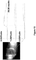
- Fig. 13 Organoid chamber during optical mapping of electrical signals.
- the image shows pseudo-color of fluorescence intensity using voltage-sensitive fluorescent dye (di-4-ANEPPS), with individual tracings of signal intensity (i.e. voltage) vs. time at multiple sites on the organoid, indicating propagation of the electrical wave from left to right.
- di-4-ANEPPS voltage-sensitive fluorescent dye
- the construction of the bioreactor 100 and related equipment overcomes the deficiencies associated with the conventional equipment in that the organoid chamber is grown directly on an instrument, in this case the cannula 140, that is configured to be used in the testing phase as well as the initial culturing phase in which the organoid is generated.
- the construction of the bioreactor 100 of the present invention thus avoids the need to physically detach the organoid from the balloon catheter and then transfer and attach the organoid to a test instrument, such as pressure transducer equipment, using a suture or similar method-this process often results in damage to the organoid and compromises sterility and viability of the living engineered tissue.
- the human organoid chambers and the related bioreactor systems disclosed herein have a vast number of practical applications for creating functional in vitro models the human heart with biomimetic structural and functional properties for enhanced drug/toxicity screening and other (cell, gene) therapeutic discovery/preclinical testing applications. Accordingly, by creating a biomimetic in vitro surrogate for the human heart, the present technology helps bridge the longstanding gap between traditional cell culture systems and in vivo animal models and eventual clinical trials.
- the present invention essentially provides an in vitro preclinical human organ model with reduced and controlled biocomplexity for improved screening applications that can improve the efficiency and success rate of novel or repurposed drugs.
- Creating tissues from human adult pluripotent stem cells e.g., iPSCs
- the human organoid chambers generated using the bioreactor systems disclosed herein are also uniquely suitable when clinically relevant pressure-volume characteristics are required, or when optical mapping of electrophysiological characteristics is of interest.
- 3D cell alignment is generated by silicone balloon surface patterning. More specifically, various surface patterns can be formed on the outer surface of the balloon 120. These textured balloons induce cell and matrix alignment in the 3D organoid chambers, more like the natural heart wall.
- the resulting anisotropy fundamentally impacts the structural organization of the tissue as well as the resulting mechanical properties and electrical conduction properties, providing a novel strategy to improve overall pump function of the organoids.
- the hCMs are ready for use after the single cells have re-aggregated into small clusters of cells (such as a cluster of 15-20 cells).
- the plate on which the hCMs are present should be inspected prior to cell transfer and is a substantial number of cells have attached to the plate, the cells can be scraped with a cell lifter, such as a Corning cell lifter.
- the cell/tissue culture is then further prepared by performing the steps of: pelleting the cells (300 x g for a selected time period (e.g., three minutes)) and then aspirating off the supernatant, leaving approximately 500 ⁇ L of solution (resulting solution).
- the supernatant is then resuspended in the 500 ⁇ L of solution and is transferred to a different vessel, such as an Eppendorf tube.
- the cells undergo a pelleting procedure again (200 x g) in a microfuge for a predetermined period of time (e.g., 5 minutes).
- the resulting solution (tissue culture) is then set aside.
- the cannula 140 can have one or more of the following features/properties:
- the porous support ring (first ring 130) can be in the form of a ring that is formed (cut/stamped) from a 1/16" thick sheet of hydrophilic-treated porous polyethylene with 70-um pore size; however, the first ring 130 can be formed from other suitable materials and have other properties.
- the porous support ring 130 can have one or more of the following features/properties:
- the first ring 130 can be cut from 1/16" thick sheet of hydrophilic-treated porous polyethylene with 70-um pore size.
- the O-ring 135 can be a silicone rubber O-ring with an inner diameter of about 5/64" and an outer diameter of about 13/64", with a thickness of about 1/16".
- the O-ring 135 can have one or more of the following features:
- the O-ring 135 and porous ring 130 can be coupled to one another (at least temporarily) prior to coupling to the cannula 140.
- Bovine Type I Collagen (Life Technologies, Cat # A10644-01) 10x Minimum Essential Medium Eagle (MEM) (Sigma, Cat # M0275) Bovine Serum Albumin (Sigma, Cat # A9418) High Vacuum Grease (Dow Corning) (Fisher Scientific, Cat # 146355D) PBS (Sigma, Cat # P3813) Matrigel - hESC-qualified matrix (BD Biosciences, Cat # 354277) in 150 ⁇ L aliquots HEPES (Sigma, Cat # H4034) Dulbecco's Modified Eagle's Medium (DMEM) - high glucose (Sigma, Cat # D5648) Neonatal Bovine Serum (NBS) (Atlanta Biologics, Cat # S11250) Penicillin-Streptomycin (Pen-Strep) (CellGro, Cat # 30-002-CI) Amphotericin B (Sigma, Cat # A2411-1G) Agarose I (VWR, Cat # 0710-25G) Silicon
Landscapes
- Health & Medical Sciences (AREA)
- Life Sciences & Earth Sciences (AREA)
- Engineering & Computer Science (AREA)
- Wood Science & Technology (AREA)
- Organic Chemistry (AREA)
- Bioinformatics & Cheminformatics (AREA)
- Chemical & Material Sciences (AREA)
- Zoology (AREA)
- Genetics & Genomics (AREA)
- Biotechnology (AREA)
- Biomedical Technology (AREA)
- Biochemistry (AREA)
- Sustainable Development (AREA)
- General Engineering & Computer Science (AREA)
- General Health & Medical Sciences (AREA)
- Microbiology (AREA)
- Clinical Laboratory Science (AREA)
- Molecular Biology (AREA)
- Physics & Mathematics (AREA)
- Electromagnetism (AREA)
- Cell Biology (AREA)
- Apparatus Associated With Microorganisms And Enzymes (AREA)
Description
- The present invention is generally directed to an organoid bioreactor and more specifically, to an apparatus and method for engineering cardiac organoids (organoid chambers) from a cell source (e.g., human cells) with the apparatus being configured to pump fluid and mimic key aspects of natural heart pump function.
- Repairing a damaged heart remains a major challenge since the human heart has only a limited capacity to regenerate itself and damage to the heart muscle usually results in irreversible cardiac dysfunction. Much research is ongoing to develop technologies that may allow the refurbishing of failing myocardium with new muscle. Many of the existing cardiac tissue constructs used for in vitro models are in the form of tissue strips or patches. These tissue strips and patches can be used to measure contractile force, but cannot directly generate the types of measures that cardiologists are trained to understand, such as volume, pressure, ejection fraction, and stroke work. More recently, techniques have been developed to produce cardiac tissue chambers (organoids) that can generate these types of measures (see e.g. Lee E J et al. (2008), Tissue Engineering: Part A, col. 14, No. 2, pages 215-225), and these newer techniques require a number of complex steps.
- For instance, techniques for creating a cardiac organoid typically require 1) introducing a cold cell-matrix solution into a an outer cup-shaped mold; 2) inflating a balloon catheter in the cell-matrix solution to a desired chamber size to form the inner mold boundary; 3) placing a small ring above the balloon contacting the cell-matrix solution to prevent tissue slippage during culture; 4) removing the outer cup-shaped mold after a specified time period, such as 24 hours; 5) incubating the remaining cell-matrix solution with the balloon catheter for a specified time period, such as 7 to 10 days, during which the engineered cardiac tissue (organoid) would form a coordinated network compacted around the balloon; 6) carefully deflating the balloon and removing the organoid from the deflated balloon catheter following the incubation period; and 7) connecting the organoid to an isolated heart setup by suturing it to a fluid-filled cannula.
- While these newer techniques have been effective in generating the types of measures that are important for cardiologists in evaluating the efficacy of the engineered cardiac tissue, they require the investigators to be very delicate with the organoid when removing the balloon catheter and suturing the organoid to the cannula so as to avoid damaging or compromising the structure of the organoid.
- A bioreactor system for preparing a cardiac organoid chamber and for subsequent testing thereof is described herein and shown in the exemplary drawing figures. The bioreactor system includes a first vessel having a hollow interior and an open top. A first cover is mated with the open top of the first vessel. The first cover has a first opening formed therein. The system further includes a cannula having a lumen that extends from an open first end to an open second end. The cannula is disposed within the first opening of the first cover such that a portion of the cannula lies below the first cover and for insertion into the hollow interior of the first vessel. A porous ring is coupled to the cannula at or proximate the open second end thereof. The system also includes a balloon catheter having an inflatable balloon at a distal end of a catheter shaft (e.g., a flexible tubular structure). The balloon catheter is adapted to pass through the lumen of the cannula when the balloon is in a deflated state. The balloon catheter is axially adjustable within the lumen to allow the balloon in an inflated state to be disposed adjacent: (1) the open second end of the cannula; and (2) the porous ring for preparing the cardiac organoid chamber about the inflated balloon and porous ring. The cannula and porous ring construction and combination allows for the balloon to be deflated and removed from the lumen of the cannula while the engineered cardiac organoid chamber remains attached to the porous ring. This permits the testing of organoid pump function, such as organoid pressure and volume characteristics, without having to transfer the engineered cardiac organoid from one tool (e.g., an incubation tool) to another tool (e.g., a functional testing apparatus), which can damage the organoid and compromise sterility and viability of the living tissue.
-
-
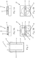
Figs. 1A-C are schematic illustrations of cardiac organoid chamber culture system (bioreactor) showing inFig. 1A tissue casting between inner silicone balloon and outer agarose mold for first 24 hours; tissue after removal of agarose mold and placement in a cell culture media as shown inFig. 1B ; and the entire bioreactor with carbon rods in place for electrical pacing as shown inFig. 1C ; -
Fig. 2 is side view of the entire bioreactor design including a jig for alignment of external and internal components of the hCOC mold; -
Figs. 3A and 3B show side and top views, respectively, of a cannula/electrode jig; -
Fig. 4A and 4B show side and top views, respectively, of an agarose mold jig; -
Fig. 5 is a cross-sectional view showing a mandrel (test tube) positioned with the agarose mold; -
Fig. 6 is a cross-sectional view showing the agarose mold with the mandrel removed; -
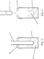
Fig. 7 is a cross-sectional view showing a balloon catheter being threaded through a lumen of a cannula; -
Fig. 8 is a cross-sectional view showing the balloon of the catheter inflated; -
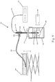
Fig. 9 is a schematic of an exemplary organoid function testing system; -
Fig. 10 is a schematic of another exemplary organoid function testing system; -
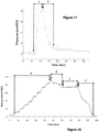
Fig. 11 is a graph showing the organoid chamber pressure versus time during a test without the rubber O-ring seal in place; -
Fig. 12 is a graph showing the organoid chamber pressure versus time with the rubber O-ring seal in place; and -
Fig. 13 is a graph showing the organoid chamber during optical mapping of electrical signals. - In accordance with the present invention, an apparatus and method are provided for preparing an engineered organoid structure and more specifically, for preparing a cardiac organoid (cardiac organoid chamber) using a bioreactor, with the organoid configured to pump fluid and mimic key aspects of natural heart pump function. Unlike the conventional engineering and testing techniques described herein, the apparatus and system of the present invention does not require removal of the cardiac organoid from one instrument and then placement of the engineered cardiac organoid on a second instrument for testing the organoid pump function. Appendix A sets forth a list of exemplary materials that can be used in the apparatus (bioreactor) and associated test equipment that are described herein.
- Referring to
Figs. 1-8 , to create cell-populated cardiac organoid chambers, a bioreactor (system) 100 is used. As described herein, thebioreactor 100 is part of an overall system that is configured for testing the organoid function, including pump function, after the organoid is engineered in thebioreactor 100. - One
exemplary bioreactor 100 is prepared as follows. Aballoon catheter 110 is used in thebioreactor 100 and comprises anelongated shaft 112 that has a distal end 114. Theshaft 112 can be in the form of a tubular structure that is flexible. Theshaft 112 includes at least one lumen formed therein. At the distal end 114, aninflatable balloon 120 is disposed. Theinflatable balloon 120 is in fluid communication with the lumen formed in theshaft 112 such that an inflation fluid can be delivered through the lumen or removed through the lumen or another lumen for changing the inflation characteristics of theballoon 120. - It will be appreciated that the
shaft 112 can extend through theballoon 120 to provide additional support and in this embodiment theballoon 120 surrounds the distal end of the shaft. Alternatively, theballoon 120 can be unsupported and be sealingly attached to the distal end of theshaft 112 such that at least a portion of theballoon 120 is unsupported and spaced from theshaft 112. - The
catheter 110 can be constructed by modifying an existing balloon catheter, such as a flexible Foley catheter. In particular, the distal tip that is typically found in Foley catheters can be removed. When the tip of the catheter is cut off, the bottom of theballoon 120 is flush with the end of thecatheter shaft 112. The open cut end of the shaft can be sealed with an appropriate material, such as silicone (caulking). - A first ring (porous ring) 130 is used during the cell culturing process as described below. The
first ring 130 can be in the form of a hydrophilic porous polyethylene ring. Thefirst ring 130 is for use with afirst cannula 140. Thefirst cannula 140 is in the form of an elongated cannula that has adistal end 142 and an oppositeproximal end 144. Thefirst cannula 140 is formed of a suitable biocompatible material that will not corrode, rust, degrade, dissolve, etc., in the culture media that is used in thebioreactor 100. In addition, thefirst cannula 140 is formed of a material that can be easily sterilized, such as by autoclave, UV exposure, etc. - In one embodiment, the
first cannula 140 is a 9-gauge stainless steel tube of predetermined length (e.g., about 8 cm) and having a predetermined width (e.g., an outer diameter (O/D) of about 0.15 inch and an inner diameter (I/D) of about 0.12 inch). - The
first ring 130 is centered on thecannula 140 and an O-ring 135 is preferably used in combination with the first ring 130 (See,Fig. 9 ). The O-ring 135 is formed of a suitable material, such as rubber. The O-ring 135 is placed on thecannula 140 and thefirst ring 130 is arranged such that it is disposed at the distal end of thecannula 140. The O-ring 135 is pushed down on top of thefirst ring 130 without displacing thefirst ring 130 from the distal end of thecannula 140. The O-ring 135 provides a water-tight seal to prevent fluid leakage. - It will be appreciated that the
cannula 140 has sufficient rigidity to allow theinflated balloon 120 to be held in place at the distal end of thecannula 140 once thecatheter 110 is inserted through the lumen of thecannula 140 and theballoon 120 is inflated as described below. In addition, thecannula 140 is sufficiently rigid such that it holds its shape and allows the insertion and removal of thecatheter 110 from the lumen thereof and further is not deformed by the O-ring 135 which is sealingly disposed thereabout. - As shown in
Figs. 5-6 , amold 150 is prepared by preparing a suitable mold material which is then disposed within a first mold container (vessel) 152. Thefirst mold container 152 has a hollow interior and can have a rectangular shape. A predetermined amount of the mold material is then added to the hollow interior of thefirst mold container 152. In one exemplary embodiment, the mold material is an Agarose hydrogel solution, such as a 2% Agarose solution, that provides structural support yet is permeable and non-adherent. In one embodiment, about 20 mls of the Agarose solution is added to thefirst mold container 152. The mold is then prepared by introducing amandrel 153 into the mold material. Themandrel 153 can be in the form of a cylindrical structure with a hemispherical tip, such as a test tube (e.g., a 13 mm test tube). Themandrel 153 is centered within thefirst mold container 152 and is also positioned such that it is normal (perpendicular) to the mold material within thefirst mold container 152. It will be appreciated that onemandrel 153 forms one mold cavity when the molding process is complete and the mandrel is withdrawn. - As shown in
Figs. 4A, 4B ,5 and 6 , themandrel 153 can be suspended in the mold material using a first support member (cover) orfirst jig 200. Thefirst jig 200 is designed to cover thefirst mold container 152 much like a shoe box cover covers the bottom of the box. However, it will be appreciated that other jig designs can be used in the present invention. Thefirst jig 200 has atop surface 202 andside walls 204. Thetop surface 202 has anopening 206 formed therein, with theopening 206 being configured to receive themandrel 153. Themandrel 153 can thus be supported by thefirst jig 200 such that themandrel 153 can be locked in a desired position such that the desired spacing between the bottom of themandrel 153 and the bottom of thefirst mold container 153 is achieved. Themandrel 153 can thus be slidingly moved within theopening 206 and alock mechanism 210 can be used to lock themandrel 153 in the desired position. For example, afirst set screw 212 that extends through oneside wall 204 can be used to secure themandrel 153 in place within the mold material that is within thefirst mold container 152. To move themandrel 153, theset screw 212 is loosened to allow axial movement of themandrel 153 and when themandrel 153 is in the desired position, theset screw 212 is tightened. Other locking mechanisms can be used. - In one embodiment, the mandrel is positioned within the mold material (Agarose solution) so that there is about 0.5 to 0.75 cm of the mold material between the bottom of the mandrel and the bottom of the
first mold container 152. After the mold material has set, the mandrel is carefully removed from the mold material leaving a void (e.g., the imprint of the test tube) in the mold material. This void defines the formedmold cavity 155 which is cup-shaped (Figs. 1A and6 ). The mold formed within thefirst mold container 152 is then placed under a UV light or the like to sterilize the mold. - Additional steps can be performed to ready the mold for use. For example, about 1.5 ml of a sterile 2% BSA (bovine serum albumin) solution can be added to the mold and then the
first mold container 152 is covered and the mold is incubated for a predetermined period of time (e.g., 1 hour at about 37°C). After the incubation period is completed, the mold can be washed with one or more solutions including a phosphate-buffered saline and deionized water. In one embodiment, the wash process involves washing the mold three times with a phosphate buffered saline solution and one time with deionized water. The deionized water is then removed from the mold and the mold is allowed to dry. - The
mold 150 can thus be formed of 2% agarose in phosphate-buffered saline (PBS). - In accordance with the present invention and as shown in
Figs. 3A and 3B , a second support member (cover) orfirst jig 220 is provided to mate with an open end of a vessel or container, such asfirst mold container 152. Thesecond jig 220 is designed to cover thefirst mold container 152 and another vessel used subsequently as described below. Thesecond jig 220 has atop surface 222 and side walls 224 (which can be fitted over the side walls of the vessel 300). Thetop surface 222 has a plurality of openings formed therein. In the illustrated embodiment, thesecond jig 220 has threeopenings second opening 232 being the middle one. - It will be appreciated that the
openings opening 232 is different than theopenings opening 232 which represent a middle opening between theopenings openings - As with the
first jig 200, thesecond jig 220 has a lock mechanism for securely positioning and retaining members (tools/instruments) that are inserted into any one of theopenings set screws 240 can be used and in particular, theset screws 240 pass through one or more of theside walls 224. In the illustrated embodiment, theset screw 240 for themiddle opening 232 passes through oneside wall 224, while the other two setscrews 240 for theopenings opposite side wall 224 to facilitate unencumbered manipulation of individual set screws 240. Theset screws 240 can be in the form of nylon screws to avoid corrosion and minimize damage to inserted tools/instruments. - The
middle opening 232 is constructed to receive thecannula 140. The distal end of thecannula 140 is thus passed through themiddle opening 232 so as to position the distal end of thecannula 140 below thesecond jig 220. It will be appreciated that thecannula 140 includes thefirst ring 130 and the O-ring 135 (both of which are disposed at or near the distal end of the cannula). - To further prepare the engineered cardiac organoid chamber, the
catheter 110 is passed through the lumen formed in thecannula 140. Theballoon 120 is in a deflated state as thecatheter 110 is passed through the lumen (Fig. 7 ). Thecatheter 110 is advanced through the lumen until theballoon 120 extends beyond the open distal end of thecannula 140. Theballoon 120 is then inflated as by injecting an inflation fluid (e.g., deionized water) into theballoon 120. After theballoon 120 is inflated, thecatheter 110 is gently pulled back so as to position theinflated balloon 120 against the distal end of the cannula 140 (Fig. 8 ). Theinflated balloon 120 thus lies directly below the first ring 130 (support ring). - The
set screw 240 can be used to secure thecannula 140 in place relative to thesecond jig 220. - The
catheter 110 is typically a flexible member that is sized to be slightly smaller than the lumen of the cannula and therefore, a frictional coupling can be formed between thecatheter 110 and thecannula 140. In any event, thecatheter 110 slidingly travels within the lumen of thecannula 140 to permit repositioning thereof as well as insertion and removal of thecatheter 110. - Once the
catheter 110 is in the desired position described above relative tocannula 140, thecatheter 110 can be secured in the desired position using a retaining mechanism. For example, aclamp 250 or the like can be used to hold thecatheter 110 in place or a set screw can be used to apply tension on thecatheter 110 that is within the lumen of thecannula 140. Alternatively, a frictional fit can exist between thecatheter 110 and thecannula 140 and thus, thecatheter 110 is frictionally held in place within thecannula 140. The above techniques assist in maintaining alignment of theinner balloon 120 within theouter agarose mold 150 as described above and further detailed below. - Once the
balloon catheter 110 is secured in the desired location with theballoon 120 being inflated, thesecond jig 220 is then inserted into thefirst mold container 152 that contains the formed cup-shapedagarose mold 150. Theinflated balloon 120 can then be further manipulated where needed to position theballoon 120 in a target location in the cup-shaped mold cavity. For example, theballoon 120 can be centered within the mold cavity such that there is approximately 2 mm of space, uniformly distributed, between the agarose wall and theballoon 120. The volume of theballoon 120 can also be adjusted to increase or decrease this gap spacing, which ultimately determines the wall thickness of the resulting organoid chamber. Additionally, the position of thesecond jig 220 can be adjusted and in particular, thesecond jig 220 can be positioned at angle to aid in alignment of theballoon 120 within the mold cavity. Theballoon 120 is also lowered within themold cavity 155 until it is at a target location. For example, theballoon 120 can be lowered until theballoon 120 is disposed approximately 2 mm from the bottom of the agarose mold. Theballoon 120 can thus be concentrically located within themold 150. It will be appreciated that the 2 mm sized spacing mentioned above is merely exemplary and not limiting of the present invention since in different applications, the dimension of this spacing can be different than 2 mm. For example, theballoon 120 can be spaced (uniformly) from the mold a distance between about 0.5 mm and about 3mm. The gap is shown in an exaggerated state in the figures to allow the balloon and side walls of the mold cavity to be seen. - In accordance with the present invention, human cardiomyocytes (hCMs) are used as part of the process for forming the human engineered cardiac organoid chamber (hCOC). As described in greater detail below, an ice-cold sterile collagen solution is prepared using purified bovine dermal type 1 collagen. This gel is mixed with Matrigel basement membrane matrix and a cell suspension according to a predetermined ratio. This results in a cold cell-matrix solution being formed and the detailed Example set forth below describes the detailed steps for creating one cold cell-matrix solution.
- One of the
unoccupied openings dedicated port 235 can be formed for delivering the cold cell-matrix solution (tissue culture mixture) into themold cavity 155 using a suitable instrument (Fig. 1A ). For example, a pipette (e.g., a 1000 mL pipet) can be used to deliver the cold cell-matrix solution. The cold cell-matrix solution thus flows around theinflated balloon 120 and is contained within themold cavity 155 defined by the gap space between the outer cup-shapedmold 150 and around theinflated balloon 120 and thecannula 140. Thefirst ring 130 is to be entirely submerged in the cold cell-matrix solution and thus, the axial position of theballoon 120, or the volume of the cold cell-matrix solution, can be adjusted to ensure that thefirst ring 130 remains submerged. Thefirst ring 130 serves to prevent tissue slippage during tissue culture. - The entire assembly is then incubated under prescribed conditions that result in initiation of collagen gel polymerization. For example, the assembly can be incubated at 37°C in 20% O2, 5% CO2 and 95% ambient humidity for two hours. In addition, the tissues can be "floated" two hours later by adding enough neonatal bovine serum (NBS)-supplemented culture media to completely submerge the tissue and then the assembly can be returned to the incubator (
Fig. 1A ). - After a predetermined period of time passes (e.g., 48 hours) and the tissue has undergone self-assembly construction within the mold cavity of the
first mold container 152, the jig assembly (defined by thejig 220 and attachedcannula 140 and balloon catheter 110) is removed from themold cavity 155. The jig assembly is then placed on top of asecond container 300 which can be similar or identical to thefirst mold container 152 with the exception that thesecond container 300 does not include an agarose mold and instead is empty. The dimensions of thesecond container 300 can be the same as thefirst container 152. Thesecond container 300 is also sterilized prior to mating the jig assembly to the open top of thesecond container 300. - A culture media is then added to the
second container 300 through the media access port (e.g., opening 235) formed in the second jig 220 (Fig. 1B ). Half of the culture media is renewed daily. - As the tissue is prepared in the culture media contained within the
second container 300, theballoon 120 remains inflated and thefirst ring 130 remains immediately above theinflated balloon 120 and surrounds thecannula 140. Thesecond container 300 with the culture media is maintained in the incubator for a predetermined period of time, such as 7 to 10 days. During this time, the myocytes begin contracting and forming a coordinated network as the engineered tissue becomes compacted around theballoon 120. In other words, an engineered cardiac organoid chamber is generated around theballoon 120 and once theballoon 120 is removed, an organoid 199 (Fig. 1C ) remains in place and is sealingly coupled to thefirst ring 130 disposed about thecannula 140. - In accordance with the present invention, beating cardiac chambers (cardiac organoids) were created from human cardiac cells. The present invention combines organoid chamber engineering techniques with human cardiomyocytes derived from pluripotent stem cells. This combination results in a unique human beating heart chamber that provides a new bridge between traditional in vitro culture systems and preclinical testing in animals and human patients.
- After a predetermined period of time, such as 7-10 days of culture, the spontaneously beating cardiac organoid is prepared for testing. In particular, pacing and mapping experiments can be performed beginning at around day 7 to 10. The
catheter 110 is removed from the jig assembly by first deflating theballoon 120 carefully while leaving behind the cardiac organoid. The clamp 250 (FIG. 1C ) is loosened to allow for removal of thecatheter 110. One technique for removing thecatheter 110 is to gently twist thecatheter 110 back and forth to check for any attachment of the tissue to theballoon 120. If any attachment of the tissue is noticed, the tissue can be returned to the incubator for 15 minutes as this usually helps the tissue detach from theballoon 120. - The
catheter 110, withballoon 120 deflated, is then gently withdrawn (removed) out of the open proximal end of the cannula 140 (seeFig. 1C ). A small amount (100-200 µl) of NBS media can be added to the open proximal end of thecannula 140 as thecatheter 110 is removed. Often, a vacuum forms in the mold cavity (chamber) as thecatheter 110 is removed. Adding the NBS media can help mitigate the vacuum if formed. Additionally, as thecatheter 110 is removed, thecatheter 110 can be twisted back and forth as this also aids in releasing any vacuum. - Preferably, the tissue (cardiac organoid) is tested in a closed-
loop system 400 such as the one shown inFig. 9 (which is a schematic of one exemplary organoid function testing system). Thesystem 400 includes thebioreactor 100 and in particular, thesecond container 300 that is filled with culture media with the organoid shown at 199. Unlike the conventional technique in which the organoid was physically removed from the balloon catheter and then sutured or otherwise attaching to a test instrument, theorganoid 199 generated according to the teachings of the present invention is grown in-situ about thecannula 140 and in particular, theorganoid 199 is attached to thecannula 140 via theporous support ring 130 and the water-tight O-ring seal 135 to prevent fluid leakage. - A
connector 410, such as a T-connector, is sealingly and fluidly connected to the open proximal end of thecannula 140. Theconnector 410 thus has afirst leg 412 and asecond leg 414 to which other objects can be attached. Anopen fluid reservoir 420 is sealingly connected to thefirst leg 412 by aconduit 430. Theopen fluid reservoir 420 contains the culture media and can include additional substances, such as phenol red to enable pH to be monitored and enhance the organoid image contrast. Theconduit 430 can be in the form of flexible tubing which allows flow of the culture media. - The mean chamber pressure (within the organoid 199) can be controlled by adjusting the height of the
open fluid reservoir 420 and in particular, theopen fluid reservoir 420 can sit on an adjustable platform (jack 425) that allows the height of thereservoir 420 to be adjusted (e.g., manually or via motor control) to control the hydrostatic pressure load on theorganoid 199. Chamber pressures are measured relative to theexternal reservoir 420 using asuitable pressure transducer 440, such as an indwelling electronic pressure transducer. Thetransducer 440 has aprobe element 442 that passes through thesecond leg 414 and through the lumen of thecannula 140 into the center of theorganoid 199. Theprobe element 442 is sealed tosecond leg 414 with a suitable sealing material 415, such as a wad of malleable gum to maintain a closed fluid connection via theconduit 430 which is connected to theopen fluid reservoir 420. The resulting passive and active pressures within the organoid chamber are recorded by thepressure transducer 440 to assess contractile function. A high-speed video camera (digital camera) 450 is used to monitor changes in organoid size synchronized with the pressure recordings. - For electrophysiologically controlled measurements of contractile performance, or for chronic electrical stimulation during organoid culture, a pair of electrodes 500 (connected to an electrical stimulator apparatus) is used to electrically pace the organoid chamber using a technique known as electrical field stimulation. The
electrodes 500 are received throughopenings second jig 220. Since theopenings opening 232, theelectrodes 500 are maintained at a fixed position and spaced a fixed distance from the cannula 140 (and thus from the organoid), to ensure a well-defined electrical field gradient during pacing. Any number of techniques can be used to securely attach or couple theelectrodes 500 to thesecond jig 220, such as nylon setscrews 240. As shown in the figures, theelectrodes 500 depend downwardly into the culture media and are at least generally parallel to thecannula 140. Theelectrodes 500 can be selected from any number of suitable conductive and non-corrosive electrode materials, including carbon rod electrodes. Theelectrodes 500 are thus proximate and spaced from theorganoid 199 that is attached to thefirst ring 130 at the distal end of thecannula 140. - A resulting extracellular electrogram can be recorded using conventional devices, such as a microelectrode AC amplifier that includes a band-pass filter and is sampled at a predetermined frequency. Extracellular voltage, chamber pressure, and digital video can be acquired simultaneously using an A/D converter on a personal computer. Chamber cross-sectional area can be measured from the digital video by applying grayscale threshold and automatic detection of the tissue boundary using suitable image processing software, such as ImageJ.
- The following graphs show pressure within the organoid chamber versus time without the O-ring seal 135 (
Fig. 11 ) and with the O-ring seal 135 (Fig. 12 ). The pressure data are measured using a Millar Mikro-Tip pressure transducer threaded through thecannula 140 and into the organoid lumen, with the end of the tube/transducer sealed with modeling clay to create a closed fluid system (Fig. 10 ). The data inFig. 11 clearly shows that without the O-ring seal 135, the pressure load on the organoid can be increased but it rapidly falls as the fluid leaks out of the system. To identify the source of the leak, we added dye to fluid within the chamber to visualize that the fluid was leaking at the interface between theporous support ring 130 and therigid tube 140. When the O-ring 135 was added to create a water-tight seal at this interface, then we were able to increase the lumen pressure to higher levels and hold the pressure steady to allow measurements at controlled loading pressures (Fig. 12 ). This is essential to accurately evaluate the load-dependent pump function of the organoid chamber, which is a fundamental and clinically relevant characteristic of natural heart pump function. We have also demonstrated optical mapping of electrical activation waves over the surface of the organoid chamber using voltage sensitive fluorescent dyes (Fig. 13 ). -
Fig. 11 : Organoid chamber pressure versus time during example test without the rubber O-ring seal in place. When the pressure is increased by about 8 mmH2O (Region A), the pressure is not held steady, and rapidly falls back toward baseline in less than 10 seconds (Region B) due to fluid leaking out of the chamber. Note that oscillations in the pressure signal are due to beating of the organoid during testing. Accurate analysis of these oscillations is greatly hampered by the non-steady nature of the loading pressure. -
Fig. 12 : Organoid chamber pressure versus time during example test with the rubber O-ring seal in place. Region A shows incremental step loading of approximately 5 mmH2O every 5 seconds from baseline of about 2 mmH2O up to 40 mmH2O. The steady regions after each increment demonstrate that the closed system is able to hold constant pressures. After some adjustment near the maximum (Region B), the pressure was reduced to approximately 35 mmH2O and held steady for about 20 seconds (Region C), indicating no appreciable fluid leakage in the system. The pressure was then rapidly reduced back to zero at the end of the test (Region C), indicating an ability to accurately control the organoid chamber pressure over a wide range. Note the difference in scale for both the pressure axis and the time axis inFig. 11 , which is very zoomed in compared toFig. 12 . -
Fig. 13 : Organoid chamber during optical mapping of electrical signals. The image shows pseudo-color of fluorescence intensity using voltage-sensitive fluorescent dye (di-4-ANEPPS), with individual tracings of signal intensity (i.e. voltage) vs. time at multiple sites on the organoid, indicating propagation of the electrical wave from left to right. - The construction of the
bioreactor 100 and related equipment overcomes the deficiencies associated with the conventional equipment in that the organoid chamber is grown directly on an instrument, in this case thecannula 140, that is configured to be used in the testing phase as well as the initial culturing phase in which the organoid is generated. The construction of thebioreactor 100 of the present invention thus avoids the need to physically detach the organoid from the balloon catheter and then transfer and attach the organoid to a test instrument, such as pressure transducer equipment, using a suture or similar method-this process often results in damage to the organoid and compromises sterility and viability of the living engineered tissue. - The human organoid chambers and the related bioreactor systems disclosed herein have a vast number of practical applications for creating functional in vitro models the human heart with biomimetic structural and functional properties for enhanced drug/toxicity screening and other (cell, gene) therapeutic discovery/preclinical testing applications. Accordingly, by creating a biomimetic in vitro surrogate for the human heart, the present technology helps bridge the longstanding gap between traditional cell culture systems and in vivo animal models and eventual clinical trials. The present invention essentially provides an in vitro preclinical human organ model with reduced and controlled biocomplexity for improved screening applications that can improve the efficiency and success rate of novel or repurposed drugs. Creating tissues from human adult pluripotent stem cells (e.g., iPSCs) can even allow patient-specific personalized drug screening for individual assessment of efficacy or toxicity.
- The human organoid chambers generated using the bioreactor systems disclosed herein are also uniquely suitable when clinically relevant pressure-volume characteristics are required, or when optical mapping of electrophysiological characteristics is of interest.
- In accordance with the present invention, 3D cell alignment is generated by silicone balloon surface patterning. More specifically, various surface patterns can be formed on the outer surface of the
balloon 120. These textured balloons induce cell and matrix alignment in the 3D organoid chambers, more like the natural heart wall. The resulting anisotropy fundamentally impacts the structural organization of the tissue as well as the resulting mechanical properties and electrical conduction properties, providing a novel strategy to improve overall pump function of the organoids. - The following examples are provided to better illustrate embodiments of the present invention. However, it is to be understood that these examples are merely illustrative in nature, and that the process embodiments of the present invention are not necessarily limited thereto.
- The hCMs are ready for use after the single cells have re-aggregated into small clusters of cells (such as a cluster of 15-20 cells). The plate on which the hCMs are present should be inspected prior to cell transfer and is a substantial number of cells have attached to the plate, the cells can be scraped with a cell lifter, such as a Corning cell lifter. The cell/tissue culture is then further prepared by performing the steps of: pelleting the cells (300 x g for a selected time period (e.g., three minutes)) and then aspirating off the supernatant, leaving approximately 500 µL of solution (resulting solution). The supernatant is then resuspended in the 500 µL of solution and is transferred to a different vessel, such as an Eppendorf tube. The cells undergo a pelleting procedure again (200 x g) in a microfuge for a predetermined period of time (e.g., 5 minutes). The resulting solution (tissue culture) is then set aside.
- Conventional protocol can be followed to prepare the hCMs for the present use. After an incubation has passed (e.g., 48 hours), the cells are transferred to a centrifuge tube (e.g., a 15 ml tube).
-
- 1. Thaw the Matrigel on ice first thing in the morning (or on ice at 4°C overnight);
- 2. Put all reagents on ice (collagen, NaOH, 10x PBS, sterile water, HEPES, 10x MEM, matrigel);
- 3. Open the excel document "Human Tissue Strip Calculations" (a software application)
- 4. Under the tab "Start Here," enter the total number of tissues desired, the tissue volume (usually 1.2 mL) and the desired cell concentration (usually 10 million hCMs/mL);
- 5. Click on the tab "Final Solution" to view the components of each mixture. You will create three solutions in three tubes: 1) a dilution of the collagen, Collagen Dilution; 2) a mixture of the collagen with MEM and HEPES, Collagen Mix; and 3) the final tissue mix containing the cells, Tissue Mixture. The final tissue mixture is composed of 2 mg/mL bovine type I collagen and 0.9 mg/mL Matrigel;
- 6. Under the "Final Solution" tab in the excel document, tissue mixture appears twice. The first set, Tissue Mixture (known [cell]), will give you the amount of each component if you know your cell concentration. With hCMs this can be quite difficult. Instead, the second set, Tissue Mixture (known cell number), can be used and which will tell you the volume in which to re-suspend the hCMs in order to achieve the correct cell concentration for the tissues. However Tissue Mixture (known cell number) is dependent on knowing the total number of cells in the solution. Typically, one assumes that all 2 million cells from the re-aggregation survive to the tissue stage, so there will be 2 million cells per re-aggregation plate;
- 7. Create each solution using the volumes prescribed in the excel document. Typically the components can be added in the order from top down (e.g., collagen then 10x PBS then 1M NaOH then sterile water for the collagen dilution solution);
- a. If using Tissue Mixture (known cell number), remove all of the supernatant from the hCM cell pellet (see section II, step 5) by gently pipetting off the supernatant with a p20 pipet and replace with the media volume described in Tissue Mixture (known cell number).
- b. It is possible to add the 10x MEM and HEPES directly to the collagen dilution to create the collagen mix. This avoids an extra pipetting step that may introduce error.
- c. Note: Depending on the lot of Matrigel used, it may be necessary to change the "Matrigel Stock Concentration" under the tab "Tissue Mix." Usually it is necessary to phone the vendor to obtain the lot's Matrigel concentration.
- d. Note: For 1 chamber (1.2 ml) these volumes are typically:
- Collagen Dilution
- 0.75 mL Collagen Stock (5 ml/ml)
- 0.12 mL 10x PBS
- 0.019 mL 1M NaOH
- 0.311 ml sterile deionized water
- Collagen Mix
- 1.056 mL Collagen Dilution (above solution)
- 0.132 mL 10x MEM
- 0.132 mL HEPES (pH 9)
- Final Tissue Mix
- 1.056 mL Collagen Mix (above solution with MEM and HEPES)
- 0.113 mL Cardiomyocytes (Resuspend cell pellet in this volume)
- 0.150 mL Matrigel
- Collagen Dilution
- To form the closed loop:
- 1. Attach the flexible tubing (from the muscle bath) to either end of a 3-way
Luer lock valve 600. - 2. Attach a 20
mL syringe 610 to the third outlet of the Luer-lock. - 3. Fill a large petri dish or
beaker 420 with culture media and place it on anadjustable jack 425. - 4. Place the open end of one of the tubes into the media in the reservoir and open the valve between the syringe and the reservoir.
- 5. Draw media back into the syringe through the tubing, being sure to avoid any air bubbles entering the tubing as you draw back.
- 6. Close the
valve 600 to thereservoir 420 and open it between thesyringe 610 and the second set oftubing 601. - 7. Connect the second set of
tubing 601 to the T-connector 410 (thestem 412 of the T). - 8. Pass the
pressure transducer 442 through the T-connector 410 so that it exits the other side.- a. Note: The transducer will eventually enter the lumen of the chamber, so it can be helpful to pre-measure the distance necessary for the transducer so that it sits appropriately through the T-connector, but also will sit in the lumen of the chamber once everything is connected (distance for transducer to travel = distance T-connector + distance hypodermic tubing).
- 9. Close the open space between the pressure transducer and the T-connector with a sealant, such as modeling clay or the like. The T-connector should now only have one end open, with the transducer sticking out of it.
- 10. Draw media through the second set of
tubing 601, again being sure to avoid entry of air bubbles. The media should be traveling through the open end of the T-connector, so be sure it is submerged. - 11. Remove the top of the
chamber bioreactor 100 and place it in the media. - 12. Submerge the chamber and tubing in media, being sure to remove any air bubbles that may be in the tubing. It may be necessary to submerge the entire top of the bioreactor, which is fine. The most important thing is to make sure all air is removed from the hypodermic tubing.
- 13. At this time, also check the position of the O-
ring 135 and move it to touch the top of the PPE ring if necessary.- a. Note: The O-ring helps seal the gap between the PPE ring and the hypodermic tubing, to ensure that maximum pressure is generated in the closed system and is detected by the transducer.
- 14. Connect the open end of the T-connector to the hypodermic tubing so that the probe of the pressure transducer is in the lumen of the chamber.
- 15. Reconnect the top of the bioreactor to the bottom half of the bioreactor.
- 16. Place the bioreactor on a
heated stage 620, on an adjustable jack in front of a high-speed camera 450.- a. Note: The pressure into the lumen of the chamber will be determined by the difference in height between the fluid in the larger reservoir, and the fluid in the bioreactor. Thus, the fluid levels in the bioreactor and the open fluid reservoir should be equal.
- 17. If needed, thread the carbon electrodes through their designated holes in the top of the bioreactor and connect them to a Grass stimulator.
- Once the closed loop system has been established, the following tests can be performed in NBS media:
- 1. Establish baseline function
- a. Measure pressure over time at spontaneous, 0.5, 1, 1.5, 2.0, 2.5, 3.0 Hz
- i. Capture both pressure and volume data at each frequency so P-V loops can be reconstructed
- ii. Use volume data for estimated ejection fraction calculations
- iii. Use pressure data for pressure vs time for each frequency (shows capture and ability to pace)
- b. Measure change in developed pressure versus luminal pressure at set frequency (I suggest 1, 1.5 or 2 Hz)
- i. Increase height of fluid reservoir by 5 mm increments and record video and pressure for 20s per step for a maximum of 40 mmH2O
- ii. This data will permit developed pressure versus luminal pressure graphs and thus test for an active Frank-Starling mechanism
- a. Measure pressure over time at spontaneous, 0.5, 1, 1.5, 2.0, 2.5, 3.0 Hz
- 2. Establish effect of pharmacologic agents on chamber function (e.g., CaCl2, Isoproterenol, Verapamil)
- a. Repeat "a" and "b" above, but in the presence of pharmacologic agents
- i. From this, changes in pressure output, Frank-Starling response and pressure-vole loops from pharmacologic agents can be evaluated
- b. Note: For known β-adrenergic agonists, spontaneous frequency changes will be important, but to control for frequency effects, also be sure to collect data at set frequencies (e.g., 1, 1.5 or 2 Hz).
- a. Repeat "a" and "b" above, but in the presence of pharmacologic agents
- The
cannula 140 can have one or more of the following features/properties: - outer diameter (OD) must be smaller than diameter of
final organoid balloon 120; - inner diameter (ID) must be large enough to allow pass through of the deflated
balloon catheter 110 and later the pressure transducer (e.g. Millar Mikro-Tip or similar) for measuring chamber lumen pressure; - material must be stiff/rigid to hold
balloon 120 precisely in place during organoid culture; - inner wall of the
cannula 140 should be smooth to allow catheter and transducer to pass easily; - outer wall can be smooth or rough but must hold porous support ring (first ring 130) for growing the organoid, and O-
ring seal 135 for pressure-to make a good seal with the O-ring 135, it is probably preferable for the outer surface to be smooth - the geometry of the
cannula 140 can be straight, or could have an integrated flare or flange or similar feature near the bottom end, against which theporous support ring 130 can be pressed to help hold the water-tight seal; - the bottom tip of the
rigid cannula 140 is slightly tapered to facilitate fitting the stiffporous support ring 130 onto the end of thecannula 140, especially if the ring/organoid needs to be removed or happens to accidentally fall off therigid cannula 140 during organoid testing; and - the
cannula 140 can be formed of other materials including polystyrene or polycarbonate tubes or various biocompatible metal alloy tubes of comparable ID/OD dimensions. - The porous support ring (first ring 130) can be in the form of a ring that is formed (cut/stamped) from a 1/16" thick sheet of hydrophilic-treated porous polyethylene with 70-um pore size; however, the
first ring 130 can be formed from other suitable materials and have other properties. - The
porous support ring 130 can have one or more of the following features/properties: - hydrophilic so that a collagen/cell solution will wick into the material when wet-can be hydrophobic and then chemically treated (e.g. with sulfuric acid) to make hydrophilic;
- readily sterilized by UV or gas sterilization;
- pore size large enough to allow solution and cells to freely wick into the material, but small enough to provide large surface area and many points of contact for firm adhesion to organoid during culture. We have successfully tested pore sizes in the range of 50 to 150 um;
- thick enough to provide needed structural stability but not too thick to absorb excess cell/matrix solution (e.g., 1/16" and 1/8" thicknesses);
- rigid enough to grab with tweezers and provide structural support for the organoid, but soft enough to cut into a spherical shape and punch a hole to fit the rigid tubing. Not too brittle, or it may snap/crumble when press-fit onto the
rigid cannula tubing 140; - Inexpensive and disposable-too difficult/impractical to clean and reuse;
- Other textured substances, including other porous plastics (e.g. polystyrene) and some porous metals (e.g. nickel foam), may be reasonable alternatives to the porous polyethylene.
- In one exemplary embodiment, the
first ring 130 can be cut from 1/16" thick sheet of hydrophilic-treated porous polyethylene with 70-um pore size. - In one exemplary embodiment, the O-
ring 135 can be a silicone rubber O-ring with an inner diameter of about 5/64" and an outer diameter of about 13/64", with a thickness of about 1/16". The O-ring 135 can have one or more of the following features: - O-
ring 135 must fit snugly on the cannula 140 (rigid tube) to form a water-tight seal, and also be flexible enough to press against theporous support ring 130 and form a water-tight seal; - Must be readily sterilized by ethanol, UV, gas or steam autoclave;
- Preferably inexpensive and may be disposable; and
- The O-
ring 135 can be formed of other materials including neoprene, polyurathane, and other standard materials for commercial soft/flexible O-ring seals. - It will be appreciated that in an alternative embodiment, the O-
ring 135 andporous ring 130 can be coupled to one another (at least temporarily) prior to coupling to thecannula 140. - Bovine Type I Collagen (Life Technologies, Cat # A10644-01)
10x Minimum Essential Medium Eagle (MEM) (Sigma, Cat # M0275)
Bovine Serum Albumin (Sigma, Cat # A9418)
High Vacuum Grease (Dow Corning) (Fisher Scientific, Cat # 146355D)
PBS (Sigma, Cat # P3813)
Matrigel - hESC-qualified matrix (BD Biosciences, Cat # 354277) in 150 µL aliquots
HEPES (Sigma, Cat # H4034)
Dulbecco's Modified Eagle's Medium (DMEM) - high glucose (Sigma, Cat # D5648)
Neonatal Bovine Serum (NBS) (Atlanta Biologics, Cat # S11250)
Penicillin-Streptomycin (Pen-Strep) (CellGro, Cat # 30-002-CI)
Amphotericin B (Sigma, Cat # A2411-1G)
Agarose I (VWR, Cat # 0710-25G)
Silicone caulking (Home Depot, Cat # GE281 3TG) - 2% BSA in PBS
0.2N HEPES, pH 9
1M NaOH
Sterile water
NBS media (DMEM, 10% NBS, 1% Pen-Strep, 0.2% Amphotericin B)
1x PBS
10x PBS - 15 mL centrifuge tube (BD Falcon, Cat # 352096)
Broad forceps (e.g.., Fisher Scientific, Cat # 10300)
Fine forceps (e.g.., Fine Science Tools, Cat # 11251-20)
Curved forceps (e.g.., Fisher Scientific, Cat # 12-460-518)
Black lab marker (VWR, Cat # 52877-310)
Non-tissue culture treated 10 cm petri dish (Fisher Scientific, Cat # 68-757-12)
20, 200 and 1000 µL pipets and pipet tips
polystyrene box, 3 x 3 x 6 cm (Container Store, Cat # 60260)
hydrophilic porous polyethylene, 1.6mm thick, 70 um pore size (Interstate Specialty Products, Cat # POR-4899-ICA-01)
6-Fr Foley catheter (Cook Medical, Cat # G17203)
Rubber mallet (McMaster-Carr, Cat # 5878A3)
11/32 stain-less steel hammer driven punch (McMaster-Carr, Cat # 3424A24)
3 mL syringe (BD, Cat # 309657)
Nylon screw compressor (Fisher Scientific, Cat # 05-834)
13-mm glass test tubes (VWR, Cat # 8900-480)
Optional: Corning Cell Lifter # 3008 (Fisher Scientific, Cat # 07-200-364)
Claims (15)
- A bioreactor system for preparing a cardiac organoid chamber and for subsequent testing thereof comprising:a first vessel having a hollow interior and an open top;a first cover for mating with the open top of the first vessel, the first cover having a first opening formed therein;a cannula having a lumen that extends from an open first end to an open second end, the cannula being disposed within the first opening of the first cover such that a portion of the cannula lies below the first cover and for insertion into the hollow interior of the first vessel;a porous ring coupled to the cannula at or proximate the open second end thereof; anda balloon catheter having an inflatable balloon at a distal end of a catheter shaft,wherein the balloon catheter is adapted to pass through the lumen of the cannula when the balloon is in a deflated state, the balloon catheter being axially adjustable within the lumen to allow the balloon in an inflated state to be disposed adjacent: (1) the open second end of the cannula; and (2) the porous ring for preparing the cardiac organoid chamber about the inflated balloon and porous ring.
- The system of claim 1, wherein the first opening is formed in a top wall of the first cover and the first cover includes second and third openings formed within the top wall, the first opening being formed between the second and third openings.
- The system of claim 2, wherein the first cover has a means for securely coupling the cannula to the first cover.
- The system of claim 3, wherein the means comprises a mechanical retaining member that holds and retains the cannula in a desired position within the first opening and relative to the first cover.
- The system of claim 4, wherein the mechanical retaining member comprises a set screw that extends through a side wall of the first cover for applying a retaining force against the cannula.
- The system of any claims 1-5, wherein the cannula is formed of a material selected from a metal and a rigid plastic and the porous ring is formed of a hydrophilic porous polyethylene material.
- The system of claim 1, wherein the porous ring is configured to prevent tissue slippage during tissue culturing to form the cardiac organoid chamber.
- The system of claim 1, further including an O-ring disposed about the cannula and in intimate contact with a top surface of the porous ring, the O-ring being configured to provide a water-tight seal.
- The system of any claims 1-5, wherein the balloon catheter has a flexible shaft that is frictionally fit within the lumen of the cannula to fix a relative position of the balloon catheter relative to the cannula.
- The system of claim 9, wherein an external device is used to retain the balloon catheter within the lumen of the catheter such that the balloon catheter remains at a fixed location within the lumen with the inflated balloon being maintained adjacent the open second end of the cannula and the porous ring.
- The system of any of claims 2-5, further including a pair of electrodes disposed within the second and third openings for permitting electrophysiologically controlled measurements or chronic electrical stimulation during culture on the prepared cardiac organoid chamber and wherein the first cover has a means for securely coupling the pair of electrodes to the first cover.
- The system of any of claims 1-5, wherein the inflatable balloon includes a surface pattern formed on an outer surface thereof for inducing cell and matrix alignment in the 3D prepared cardiac organoid chamber.
- The system of any of claims 1-5, further including:
a closed loop organoid function testing system that includes:a connector attached to the open first end of the cannula, the connector being fluidly connected to an open fluid reservoir by means of a conduit;a pressure transducer having a probe that can be passed through the lumen of the cannula after the cardiac organoid chamber is engineered and the balloon catheter is removed from the cannula, the pressure transducer being configured to measure a chamber pressure within the engineered cardiac organoid chamber; andan imaging device for monitor changes in the size of the organoid. - The system of claim 13, wherein the imaging device comprises a high-speed video camera that is synchronized with the pressure transducer to allow changes in the organoid size to be synchronized with chamber pressure measurements recorded by the pressure transducer.
- A process for engineering a cardiac organoid chamber comprising the steps of:preparing a mold in a first vessel, the mold including an open mold cavity;positioning a cannula within the open mold cavity, the cannula having a porous ring disposed about a distal end of the cannula that is disposed within the open mold cavity;inserting and passing a balloon catheter through a lumen formed in the cannula such that an inflatable balloon lies beyond the distal end of the cannula;inflating the balloon and positioning the balloon catheter such that the inflated balloon is disposed adjacent the distal end of the cannula and the porous ring;subjecting the first vessel to incubating conditions for a first period of time to promote tissue formation on the inflated balloon and porous ring;removing the combined cannula and balloon catheter from the first vessel and inserting the combined cannula and balloon catheter into a second vessel that contains cell culture media; andsubjecting the second vessel to incubating conditions for a second period of time resulting in an engineered cardiac organoid chamber being formed about the inflated balloon and the porous ring.
Applications Claiming Priority (2)
| Application Number | Priority Date | Filing Date | Title |
|---|---|---|---|
| US201462004467P | 2014-05-29 | 2014-05-29 | |
| PCT/US2015/033206 WO2015184273A1 (en) | 2014-05-29 | 2015-05-29 | Method and apparatus to prepare cardiac organoids in a bioreactor system |
Publications (3)
| Publication Number | Publication Date |
|---|---|
| EP3149147A1 EP3149147A1 (en) | 2017-04-05 |
| EP3149147A4 EP3149147A4 (en) | 2018-05-02 |
| EP3149147B1 true EP3149147B1 (en) | 2019-08-21 |
Family
ID=54699868
Family Applications (1)
| Application Number | Title | Priority Date | Filing Date |
|---|---|---|---|
| EP15800086.9A Active EP3149147B1 (en) | 2014-05-29 | 2015-05-29 | Method and apparatus to prepare cardiac organoids in a bioreactor system |
Country Status (4)
| Country | Link |
|---|---|
| US (1) | US10683476B2 (en) |
| EP (1) | EP3149147B1 (en) |
| CN (1) | CN106536707B (en) |
| WO (1) | WO2015184273A1 (en) |
Families Citing this family (25)
| Publication number | Priority date | Publication date | Assignee | Title |
|---|---|---|---|---|
| US9719068B2 (en) | 2010-05-06 | 2017-08-01 | Children's Hospital Medical Center | Methods and systems for converting precursor cells into intestinal tissues through directed differentiation |
| SG10201801654RA (en) | 2014-05-28 | 2018-04-27 | Childrens Hospital Med Ct | Methods and systems for converting precursor cells into gastric tissues through directed differentiation |
| AU2015331848B2 (en) | 2014-10-17 | 2022-03-03 | Children's Hospital Medical Center, D/B/A Cincinnati Children's Hospital Medical Center | In vivo model of human small intestine using pluripotent stem cells and methods of making and using same |
| CN109415685B (en) | 2016-05-05 | 2023-07-04 | 儿童医院医疗中心 | Method for producing gastric fundus tissue in vitro and compositions related thereto |
| EP4553082A3 (en) | 2016-11-04 | 2025-08-20 | Children's Hospital Medical Center | Liver organoid compositions and methods of making and using same |
| EP3548507A4 (en) | 2016-12-05 | 2020-07-15 | Children's Hospital Medical Center | COLON ORGANOIDS AND METHOD FOR THE PRODUCTION AND USE THEREOF |
| JP7248586B2 (en) | 2017-04-14 | 2023-03-29 | チルドレンズ ホスピタル メディカル センター | Multi-Donor Stem Cell Compositions and Methods of Making Them |
| EP3681998A1 (en) | 2017-09-11 | 2020-07-22 | IMBA-Institut für Molekulare Biotechnologie GmbH | Tumor organoid model |
| EP3694603B1 (en) | 2017-10-10 | 2026-04-08 | Children's Hospital Medical Center | Esophageal tissue and/or organoid compositions and methods of making same |
| EP3727394A4 (en) | 2017-12-21 | 2021-09-08 | Children's Hospital Medical Center | DIGITIZED HUMAN ORGANOIDS AND METHODS OF USING THEM |
| CN112055600A (en) * | 2018-03-07 | 2020-12-08 | 特温特大学 | Mold and method for preparing hollow 3D cell tissue structure |
| EP3775886A4 (en) * | 2018-03-28 | 2022-01-12 | Novoheart Limited | MODELING OF NEUROLOGICAL DISORDERS AND ATAXIA WITH CARDIAC DYSFUNCTION USING BIOTECHNOLOGICALLY MANUFACTURED CARDIAC TISSUES |
| EP4678727A3 (en) | 2018-07-26 | 2026-03-11 | Children's Hospital Medical Center | Hepato-biliary-pancreatic tissues and methods of making same |
| ES2746033A1 (en) | 2018-09-04 | 2020-03-04 | Univ Santiago Compostela | Organoid culture system |
| CA3112026A1 (en) | 2018-09-12 | 2020-03-19 | Children's Hospital Medical Center | Organoid compositions for the production of hematopoietic stem cells and derivatives thereof |
| CA3124904A1 (en) | 2019-01-14 | 2020-07-23 | President And Fellows Of Harvard College | Focused rotary jet spinning devices and methods of use thereof |
| US12600943B2 (en) | 2019-02-01 | 2026-04-14 | The University Of Hong Kong | Innervated organoid compositions and methods of making same |
| US11259687B2 (en) | 2019-04-04 | 2022-03-01 | Biosense Webster (Israel) Ltd. | Medical instrument calibration |
| US12024696B2 (en) * | 2019-05-08 | 2024-07-02 | Molecular Devices (Austria) GmbH | System and method for organoid culture |
| AU2020283048A1 (en) | 2019-05-31 | 2021-12-23 | Children's Hospital Medical Center | Shaped organoid compositions and methods of making same |
| US12497597B2 (en) | 2019-05-31 | 2025-12-16 | Children's Hospital Medical Center | Methods of generating and expanding hematopoietic stem cells |
| EP3933028A1 (en) * | 2020-06-30 | 2022-01-05 | Novoheart Limited | Devices comprising organoid chambers and uses thereof to culture, maintain, monitor or test organoids |
| EP4179065A4 (en) * | 2020-07-09 | 2024-09-11 | Novoheart International Limited | Support and system for engineered tissue |
| CN112501019B (en) * | 2020-12-03 | 2023-10-31 | 广州迈普再生医学科技股份有限公司 | Multifunctional bioreactor |
| CN113943649A (en) * | 2021-08-31 | 2022-01-18 | 宁夏宁杨食品有限公司 | Thick broad-bean sauce constant temperature fermentation cylinder |
Citations (1)
| Publication number | Priority date | Publication date | Assignee | Title |
|---|---|---|---|---|
| WO2010037783A1 (en) | 2008-10-03 | 2010-04-08 | Dsm Ip Assets B.V. | Process to make food or feed flavour with glutathione or cystein |
Family Cites Families (5)
| Publication number | Priority date | Publication date | Assignee | Title |
|---|---|---|---|---|
| AU2001243581A1 (en) * | 2000-03-11 | 2001-09-24 | The Trustees Of Columbia University In The City Of New York | Bioreactor for generating functional cartilaginous tissue |
| US20020106625A1 (en) * | 2002-02-07 | 2002-08-08 | Hung Clark T. | Bioreactor for generating functional cartilaginous tissue |
| EP2282801A1 (en) * | 2008-05-01 | 2011-02-16 | Edwards Lifesciences Corporation | Balloon deployment device and method |
| US20100249491A1 (en) | 2009-03-27 | 2010-09-30 | Circulite, Inc. | Two-piece transseptal cannula, delivery system, and method of delivery |
| FR2971255B1 (en) | 2011-02-04 | 2015-03-27 | Centre Nat Rech Scient | BIOREACTOR FOR CELL CULTURE ON THREE DIMENSIONAL SUBSTRATE |
-
2015
- 2015-05-29 CN CN201580039283.3A patent/CN106536707B/en not_active Expired - Fee Related
- 2015-05-29 WO PCT/US2015/033206 patent/WO2015184273A1/en not_active Ceased
- 2015-05-29 EP EP15800086.9A patent/EP3149147B1/en active Active
- 2015-05-29 US US15/314,870 patent/US10683476B2/en active Active
Patent Citations (1)
| Publication number | Priority date | Publication date | Assignee | Title |
|---|---|---|---|---|
| WO2010037783A1 (en) | 2008-10-03 | 2010-04-08 | Dsm Ip Assets B.V. | Process to make food or feed flavour with glutathione or cystein |
Non-Patent Citations (4)
| Title |
|---|
| "Practical Methods in Cardiovascular Research", 1 January 2005, SPRINGER-VERLAG, Berlin/Heidelberg, ISBN: 978-3-540-40763-8, article WOLFRAM-HUBERTUS ZIMMERMANN, IVAN MELNYCHENKO, MICHAEL DIDIÉ, ALI EL-ARMOUCHE, THOMAS ESCHENHAGEN: "Engineering Heart Tissue for In Vitro and In Vivo Studies", pages: 640 - 658, XP055754068, DOI: 10.1007/3-540-26574-0_34 |
| ESCHENHAGEN T, ET AL.: "THREE-DIMENSIONAL RECONSTITUTION OF EMBRYONIC CARDIOMYOCYTES IN A COLLAGEN MATRIX: A NEW HEART MUSCLE MODEL SYSTEM", THE FASEB JOURNAL, FEDERATION OF AMERICAN SOCIETIES FOR EXPERIMENTAL BIOLOGY, US, vol. 11, no. 08, 1 January 1997 (1997-01-01), US, pages 683 - 694, XP001109636, ISSN: 0892-6638 |
| EUN JUNG LEE ET AL: "Engineered Cardiac Organoid Chambers: Toward a Functional Biological Model Ventricle", TISSUE ENGINEERING PART A, MARY ANN LIEBERT, US, vol. 14, no. 2, 1 February 2008 (2008-02-01), US, pages 215 - 225, XP055460747, ISSN: 1937-3341, DOI: 10.1089/tea.2007.0351 |
| SEBASTIAN SCHAAF, AYA SHIBAMIYA, MARCO MEWE, ALEXANDRA EDER, ANDREA ST�HR, MARC N. HIRT, THOMAS RAU, WOLFRAM-HUBERTUS ZIMMERMANN, : "Human Engineered Heart Tissue as a Versatile Tool in Basic Research and Preclinical Toxicology", PLOS ONE, vol. 6, no. 10, pages e26397, XP055083859, DOI: 10.1371/journal.pone.0026397 |
Also Published As
| Publication number | Publication date |
|---|---|
| WO2015184273A1 (en) | 2015-12-03 |
| US20170107469A1 (en) | 2017-04-20 |
| EP3149147A1 (en) | 2017-04-05 |
| US10683476B2 (en) | 2020-06-16 |
| CN106536707B (en) | 2018-12-25 |
| CN106536707A (en) | 2017-03-22 |
| EP3149147A4 (en) | 2018-05-02 |
Similar Documents
| Publication | Publication Date | Title |
|---|---|---|
| EP3149147B1 (en) | Method and apparatus to prepare cardiac organoids in a bioreactor system | |
| Li et al. | Stretchable mesh microelectronics for the biointegration and stimulation of human neural organoids | |
| CA2612269C (en) | Method of producing organotypic cell cultures | |
| JP2008529691A (en) | Prosthesis manufacturing method by tissue engineering | |
| JP2004500093A (en) | Apparatus and method for measuring contraction of three-dimensional matrix body and cell tissue | |
| CN112771151B (en) | Organoids prepared using carriers for cell culture and drug toxicity evaluation methods using the same | |
| KR20050105479A (en) | Method and devices for non-traumatic movement of a probe through biological cell material | |
| EP2720731A1 (en) | Systems, methods, and devices relating to a biomimetic cellularized nephron unit | |
| US20110014597A1 (en) | Perfusable Bioreactor for the Production and/or Cultivation of a Human or Animal Blood Vessel and/or a Human or Animal Tissue | |
| WO2019156941A1 (en) | Tissue engineered scaffolds, instrumented bioreactors and methods of use thereof | |
| EP3620508B1 (en) | Microfluidic device for electrical measurement and/or stimulation | |
| HK1236220B (en) | Method and apparatus to prepare cardiac organoids in a bioreactor system | |
| HK1236220A1 (en) | Method and apparatus to prepare cardiac organoids in a bioreactor system | |
| CN121263181A (en) | Carboxamide compounds as SUMO activating and E1 ligase activating compounds for the treatment of cardiovascular diseases | |
| US20230257711A1 (en) | Support and System for Engineered Tissue | |
| KR20240014423A (en) | Organ-on-a-chips with inverted-microweir structures and uses thereof | |
| CN222524564U (en) | A multi-flux real-time electrical monitoring heart chip | |
| CN217525302U (en) | Miniature stem cell spinal cord normal position directional multiple infusion and biopsy device | |
| US20240228934A9 (en) | Nonclinical method for testing medical device surface interactions with migrating cells in simulated in vivo environment | |
| Linares | Microfluidic Platforms for Retina Electrophysiology Studies | |
| CN120519285A (en) | A separate organoid chip model and its use method | |
| Gawlitta et al. | In Vitro Muscle Model Studies | |
| Vernekar | Optimization of 3-D neural culture and extracellular electrophysiology for studying injury-induced morphological and functional changes | |
| Naraghi et al. | Novel Imaging Technologies and Their Role in Medicine: A Review | |
| Dodson | Microfluidic Platforms for Chemical and Electrical Signaling in Whole Retina Tissue |
Legal Events
| Date | Code | Title | Description |
|---|---|---|---|
| STAA | Information on the status of an ep patent application or granted ep patent |
Free format text: STATUS: THE INTERNATIONAL PUBLICATION HAS BEEN MADE |
|
| PUAI | Public reference made under article 153(3) epc to a published international application that has entered the european phase |
Free format text: ORIGINAL CODE: 0009012 |
|
| STAA | Information on the status of an ep patent application or granted ep patent |
Free format text: STATUS: REQUEST FOR EXAMINATION WAS MADE |
|
| 17P | Request for examination filed |
Effective date: 20161227 |
|
| AK | Designated contracting states |
Kind code of ref document: A1 Designated state(s): AL AT BE BG CH CY CZ DE DK EE ES FI FR GB GR HR HU IE IS IT LI LT LU LV MC MK MT NL NO PL PT RO RS SE SI SK SM TR |
|
| AX | Request for extension of the european patent |
Extension state: BA ME |
|
| DAV | Request for validation of the european patent (deleted) | ||
| DAX | Request for extension of the european patent (deleted) | ||
| REG | Reference to a national code |
Ref country code: HK Ref legal event code: DE Ref document number: 1236220 Country of ref document: HK |
|
| REG | Reference to a national code |
Ref country code: DE Ref legal event code: R079 Ref document number: 602015036379 Country of ref document: DE Free format text: PREVIOUS MAIN CLASS: C12M0001000000 Ipc: C12M0003000000 |
|
| A4 | Supplementary search report drawn up and despatched |
Effective date: 20180406 |
|
| RIC1 | Information provided on ipc code assigned before grant |
Ipc: C12N 5/00 20060101ALI20180329BHEP Ipc: C12M 3/00 20060101AFI20180329BHEP |
|
| GRAP | Despatch of communication of intention to grant a patent |
Free format text: ORIGINAL CODE: EPIDOSNIGR1 |
|
| STAA | Information on the status of an ep patent application or granted ep patent |
Free format text: STATUS: GRANT OF PATENT IS INTENDED |
|
| INTG | Intention to grant announced |
Effective date: 20190314 |
|
| GRAS | Grant fee paid |
Free format text: ORIGINAL CODE: EPIDOSNIGR3 |
|
| GRAA | (expected) grant |
Free format text: ORIGINAL CODE: 0009210 |
|
| STAA | Information on the status of an ep patent application or granted ep patent |
Free format text: STATUS: THE PATENT HAS BEEN GRANTED |
|
| AK | Designated contracting states |
Kind code of ref document: B1 Designated state(s): AL AT BE BG CH CY CZ DE DK EE ES FI FR GB GR HR HU IE IS IT LI LT LU LV MC MK MT NL NO PL PT RO RS SE SI SK SM TR |
|
| REG | Reference to a national code |
Ref country code: GB Ref legal event code: FG4D |
|
| REG | Reference to a national code |
Ref country code: CH Ref legal event code: EP |
|
| REG | Reference to a national code |
Ref country code: DE Ref legal event code: R096 Ref document number: 602015036379 Country of ref document: DE |
|
| REG | Reference to a national code |
Ref country code: AT Ref legal event code: REF Ref document number: 1169785 Country of ref document: AT Kind code of ref document: T Effective date: 20190915 |
|
| REG | Reference to a national code |
Ref country code: IE Ref legal event code: FG4D |
|
| REG | Reference to a national code |
Ref country code: SE Ref legal event code: TRGR |
|
| REG | Reference to a national code |
Ref country code: LT Ref legal event code: MG4D |
|
| REG | Reference to a national code |
Ref country code: NL Ref legal event code: MP Effective date: 20190821 |
|
| PG25 | Lapsed in a contracting state [announced via postgrant information from national office to epo] |
Ref country code: HR Free format text: LAPSE BECAUSE OF FAILURE TO SUBMIT A TRANSLATION OF THE DESCRIPTION OR TO PAY THE FEE WITHIN THE PRESCRIBED TIME-LIMIT Effective date: 20190821 Ref country code: NO Free format text: LAPSE BECAUSE OF FAILURE TO SUBMIT A TRANSLATION OF THE DESCRIPTION OR TO PAY THE FEE WITHIN THE PRESCRIBED TIME-LIMIT Effective date: 20191121 Ref country code: FI Free format text: LAPSE BECAUSE OF FAILURE TO SUBMIT A TRANSLATION OF THE DESCRIPTION OR TO PAY THE FEE WITHIN THE PRESCRIBED TIME-LIMIT Effective date: 20190821 Ref country code: PT Free format text: LAPSE BECAUSE OF FAILURE TO SUBMIT A TRANSLATION OF THE DESCRIPTION OR TO PAY THE FEE WITHIN THE PRESCRIBED TIME-LIMIT Effective date: 20191223 Ref country code: BG Free format text: LAPSE BECAUSE OF FAILURE TO SUBMIT A TRANSLATION OF THE DESCRIPTION OR TO PAY THE FEE WITHIN THE PRESCRIBED TIME-LIMIT Effective date: 20191121 Ref country code: NL Free format text: LAPSE BECAUSE OF FAILURE TO SUBMIT A TRANSLATION OF THE DESCRIPTION OR TO PAY THE FEE WITHIN THE PRESCRIBED TIME-LIMIT Effective date: 20190821 Ref country code: LT Free format text: LAPSE BECAUSE OF FAILURE TO SUBMIT A TRANSLATION OF THE DESCRIPTION OR TO PAY THE FEE WITHIN THE PRESCRIBED TIME-LIMIT Effective date: 20190821 |
|
| PG25 | Lapsed in a contracting state [announced via postgrant information from national office to epo] |
Ref country code: IS Free format text: LAPSE BECAUSE OF FAILURE TO SUBMIT A TRANSLATION OF THE DESCRIPTION OR TO PAY THE FEE WITHIN THE PRESCRIBED TIME-LIMIT Effective date: 20191221 Ref country code: GR Free format text: LAPSE BECAUSE OF FAILURE TO SUBMIT A TRANSLATION OF THE DESCRIPTION OR TO PAY THE FEE WITHIN THE PRESCRIBED TIME-LIMIT Effective date: 20191122 Ref country code: RS Free format text: LAPSE BECAUSE OF FAILURE TO SUBMIT A TRANSLATION OF THE DESCRIPTION OR TO PAY THE FEE WITHIN THE PRESCRIBED TIME-LIMIT Effective date: 20190821 Ref country code: AL Free format text: LAPSE BECAUSE OF FAILURE TO SUBMIT A TRANSLATION OF THE DESCRIPTION OR TO PAY THE FEE WITHIN THE PRESCRIBED TIME-LIMIT Effective date: 20190821 Ref country code: LV Free format text: LAPSE BECAUSE OF FAILURE TO SUBMIT A TRANSLATION OF THE DESCRIPTION OR TO PAY THE FEE WITHIN THE PRESCRIBED TIME-LIMIT Effective date: 20190821 Ref country code: ES Free format text: LAPSE BECAUSE OF FAILURE TO SUBMIT A TRANSLATION OF THE DESCRIPTION OR TO PAY THE FEE WITHIN THE PRESCRIBED TIME-LIMIT Effective date: 20190821 |
|
| REG | Reference to a national code |
Ref country code: AT Ref legal event code: MK05 Ref document number: 1169785 Country of ref document: AT Kind code of ref document: T Effective date: 20190821 |
|
| PG25 | Lapsed in a contracting state [announced via postgrant information from national office to epo] |
Ref country code: TR Free format text: LAPSE BECAUSE OF FAILURE TO SUBMIT A TRANSLATION OF THE DESCRIPTION OR TO PAY THE FEE WITHIN THE PRESCRIBED TIME-LIMIT Effective date: 20190821 |
|
| PG25 | Lapsed in a contracting state [announced via postgrant information from national office to epo] |
Ref country code: DK Free format text: LAPSE BECAUSE OF FAILURE TO SUBMIT A TRANSLATION OF THE DESCRIPTION OR TO PAY THE FEE WITHIN THE PRESCRIBED TIME-LIMIT Effective date: 20190821 Ref country code: PL Free format text: LAPSE BECAUSE OF FAILURE TO SUBMIT A TRANSLATION OF THE DESCRIPTION OR TO PAY THE FEE WITHIN THE PRESCRIBED TIME-LIMIT Effective date: 20190821 Ref country code: RO Free format text: LAPSE BECAUSE OF FAILURE TO SUBMIT A TRANSLATION OF THE DESCRIPTION OR TO PAY THE FEE WITHIN THE PRESCRIBED TIME-LIMIT Effective date: 20190821 Ref country code: EE Free format text: LAPSE BECAUSE OF FAILURE TO SUBMIT A TRANSLATION OF THE DESCRIPTION OR TO PAY THE FEE WITHIN THE PRESCRIBED TIME-LIMIT Effective date: 20190821 Ref country code: AT Free format text: LAPSE BECAUSE OF FAILURE TO SUBMIT A TRANSLATION OF THE DESCRIPTION OR TO PAY THE FEE WITHIN THE PRESCRIBED TIME-LIMIT Effective date: 20190821 |
|
| PG25 | Lapsed in a contracting state [announced via postgrant information from national office to epo] |
Ref country code: SM Free format text: LAPSE BECAUSE OF FAILURE TO SUBMIT A TRANSLATION OF THE DESCRIPTION OR TO PAY THE FEE WITHIN THE PRESCRIBED TIME-LIMIT Effective date: 20190821 Ref country code: CZ Free format text: LAPSE BECAUSE OF FAILURE TO SUBMIT A TRANSLATION OF THE DESCRIPTION OR TO PAY THE FEE WITHIN THE PRESCRIBED TIME-LIMIT Effective date: 20190821 Ref country code: SK Free format text: LAPSE BECAUSE OF FAILURE TO SUBMIT A TRANSLATION OF THE DESCRIPTION OR TO PAY THE FEE WITHIN THE PRESCRIBED TIME-LIMIT Effective date: 20190821 Ref country code: IS Free format text: LAPSE BECAUSE OF FAILURE TO SUBMIT A TRANSLATION OF THE DESCRIPTION OR TO PAY THE FEE WITHIN THE PRESCRIBED TIME-LIMIT Effective date: 20200224 |
|
| REG | Reference to a national code |
Ref country code: DE Ref legal event code: R026 Ref document number: 602015036379 Country of ref document: DE |
|
| PLBI | Opposition filed |
Free format text: ORIGINAL CODE: 0009260 |
|
| PLAX | Notice of opposition and request to file observation + time limit sent |
Free format text: ORIGINAL CODE: EPIDOSNOBS2 |
|
| 26 | Opposition filed |
Opponent name: TISSUE SYSTEMS HOLDING GMBH Effective date: 20200602 |
|
| PG2D | Information on lapse in contracting state deleted |
Ref country code: IS |
|
| PG25 | Lapsed in a contracting state [announced via postgrant information from national office to epo] |
Ref country code: SI Free format text: LAPSE BECAUSE OF FAILURE TO SUBMIT A TRANSLATION OF THE DESCRIPTION OR TO PAY THE FEE WITHIN THE PRESCRIBED TIME-LIMIT Effective date: 20190821 |
|
| PLBB | Reply of patent proprietor to notice(s) of opposition received |
Free format text: ORIGINAL CODE: EPIDOSNOBS3 |
|
| PG25 | Lapsed in a contracting state [announced via postgrant information from national office to epo] |
Ref country code: CH Free format text: LAPSE BECAUSE OF NON-PAYMENT OF DUE FEES Effective date: 20200531 Ref country code: LI Free format text: LAPSE BECAUSE OF NON-PAYMENT OF DUE FEES Effective date: 20200531 Ref country code: MC Free format text: LAPSE BECAUSE OF FAILURE TO SUBMIT A TRANSLATION OF THE DESCRIPTION OR TO PAY THE FEE WITHIN THE PRESCRIBED TIME-LIMIT Effective date: 20190821 |
|
| REG | Reference to a national code |
Ref country code: BE Ref legal event code: MM Effective date: 20200531 |
|
| PG25 | Lapsed in a contracting state [announced via postgrant information from national office to epo] |
Ref country code: LU Free format text: LAPSE BECAUSE OF NON-PAYMENT OF DUE FEES Effective date: 20200529 |
|
| PG25 | Lapsed in a contracting state [announced via postgrant information from national office to epo] |
Ref country code: IE Free format text: LAPSE BECAUSE OF NON-PAYMENT OF DUE FEES Effective date: 20200529 |
|
| PLBD | Termination of opposition procedure: decision despatched |
Free format text: ORIGINAL CODE: EPIDOSNOPC1 |
|
| PLBP | Opposition withdrawn |
Free format text: ORIGINAL CODE: 0009264 |
|
| REG | Reference to a national code |
Ref country code: DE Ref legal event code: R100 Ref document number: 602015036379 Country of ref document: DE |
|
| PG25 | Lapsed in a contracting state [announced via postgrant information from national office to epo] |
Ref country code: BE Free format text: LAPSE BECAUSE OF NON-PAYMENT OF DUE FEES Effective date: 20200531 |
|
| PLBM | Termination of opposition procedure: date of legal effect published |
Free format text: ORIGINAL CODE: 0009276 |
|
| 27C | Opposition proceedings terminated |
Effective date: 20210528 |
|
| PG25 | Lapsed in a contracting state [announced via postgrant information from national office to epo] |
Ref country code: MT Free format text: LAPSE BECAUSE OF FAILURE TO SUBMIT A TRANSLATION OF THE DESCRIPTION OR TO PAY THE FEE WITHIN THE PRESCRIBED TIME-LIMIT Effective date: 20190821 Ref country code: CY Free format text: LAPSE BECAUSE OF FAILURE TO SUBMIT A TRANSLATION OF THE DESCRIPTION OR TO PAY THE FEE WITHIN THE PRESCRIBED TIME-LIMIT Effective date: 20190821 |
|
| PG25 | Lapsed in a contracting state [announced via postgrant information from national office to epo] |
Ref country code: MK Free format text: LAPSE BECAUSE OF FAILURE TO SUBMIT A TRANSLATION OF THE DESCRIPTION OR TO PAY THE FEE WITHIN THE PRESCRIBED TIME-LIMIT Effective date: 20190821 |
|
| P01 | Opt-out of the competence of the unified patent court (upc) registered |
Effective date: 20230518 |
|
| PGFP | Annual fee paid to national office [announced via postgrant information from national office to epo] |
Ref country code: IT Payment date: 20230519 Year of fee payment: 9 Ref country code: FR Payment date: 20230525 Year of fee payment: 9 Ref country code: DE Payment date: 20230530 Year of fee payment: 9 |
|
| PGFP | Annual fee paid to national office [announced via postgrant information from national office to epo] |
Ref country code: SE Payment date: 20230527 Year of fee payment: 9 |
|
| PGFP | Annual fee paid to national office [announced via postgrant information from national office to epo] |
Ref country code: GB Payment date: 20230529 Year of fee payment: 9 |
|
| REG | Reference to a national code |
Ref country code: DE Ref legal event code: R119 Ref document number: 602015036379 Country of ref document: DE |
|
| REG | Reference to a national code |
Ref country code: SE Ref legal event code: EUG |
|
| GBPC | Gb: european patent ceased through non-payment of renewal fee |
Effective date: 20240529 |
|
| PG25 | Lapsed in a contracting state [announced via postgrant information from national office to epo] |
Ref country code: DE Free format text: LAPSE BECAUSE OF NON-PAYMENT OF DUE FEES Effective date: 20241203 |
|
| PG25 | Lapsed in a contracting state [announced via postgrant information from national office to epo] |
Ref country code: FR Free format text: LAPSE BECAUSE OF NON-PAYMENT OF DUE FEES Effective date: 20240531 |
|
| PG25 | Lapsed in a contracting state [announced via postgrant information from national office to epo] |
Ref country code: IT Free format text: LAPSE BECAUSE OF NON-PAYMENT OF DUE FEES Effective date: 20240529 Ref country code: GB Free format text: LAPSE BECAUSE OF NON-PAYMENT OF DUE FEES Effective date: 20240529 |
|
| PG25 | Lapsed in a contracting state [announced via postgrant information from national office to epo] |
Ref country code: SE Free format text: LAPSE BECAUSE OF NON-PAYMENT OF DUE FEES Effective date: 20240530 |