EP3148733B1 - Method of manufacturing a component of a turbomachine - Google Patents
Method of manufacturing a component of a turbomachine Download PDFInfo
- Publication number
- EP3148733B1 EP3148733B1 EP15726120.7A EP15726120A EP3148733B1 EP 3148733 B1 EP3148733 B1 EP 3148733B1 EP 15726120 A EP15726120 A EP 15726120A EP 3148733 B1 EP3148733 B1 EP 3148733B1
- Authority
- EP
- European Patent Office
- Prior art keywords
- container
- insert
- component
- manufacturing
- metal
- Prior art date
- Legal status (The legal status is an assumption and is not a legal conclusion. Google has not performed a legal analysis and makes no representation as to the accuracy of the status listed.)
- Active
Links
Images



Classifications
-
- B—PERFORMING OPERATIONS; TRANSPORTING
- B22—CASTING; POWDER METALLURGY
- B22F—WORKING METALLIC POWDER; MANUFACTURE OF ARTICLES FROM METALLIC POWDER; MAKING METALLIC POWDER; APPARATUS OR DEVICES SPECIALLY ADAPTED FOR METALLIC POWDER
- B22F3/00—Manufacture of workpieces or articles from metallic powder characterised by the manner of compacting or sintering; Apparatus specially adapted therefor ; Presses and furnaces
- B22F3/12—Both compacting and sintering
- B22F3/14—Both compacting and sintering simultaneously
- B22F3/15—Hot isostatic pressing
-
- F—MECHANICAL ENGINEERING; LIGHTING; HEATING; WEAPONS; BLASTING
- F04—POSITIVE - DISPLACEMENT MACHINES FOR LIQUIDS; PUMPS FOR LIQUIDS OR ELASTIC FLUIDS
- F04D—NON-POSITIVE-DISPLACEMENT PUMPS
- F04D29/00—Details, component parts, or accessories
- F04D29/26—Rotors specially for elastic fluids
- F04D29/28—Rotors specially for elastic fluids for centrifugal or helico-centrifugal pumps for radial-flow or helico-centrifugal pumps
- F04D29/284—Rotors specially for elastic fluids for centrifugal or helico-centrifugal pumps for radial-flow or helico-centrifugal pumps for compressors
-
- B—PERFORMING OPERATIONS; TRANSPORTING
- B22—CASTING; POWDER METALLURGY
- B22D—CASTING OF METALS; CASTING OF OTHER SUBSTANCES BY THE SAME PROCESSES OR DEVICES
- B22D25/00—Special casting characterised by the nature of the product
- B22D25/02—Special casting characterised by the nature of the product by its peculiarity of shape; of works of art
-
- B—PERFORMING OPERATIONS; TRANSPORTING
- B22—CASTING; POWDER METALLURGY
- B22F—WORKING METALLIC POWDER; MANUFACTURE OF ARTICLES FROM METALLIC POWDER; MAKING METALLIC POWDER; APPARATUS OR DEVICES SPECIALLY ADAPTED FOR METALLIC POWDER
- B22F3/00—Manufacture of workpieces or articles from metallic powder characterised by the manner of compacting or sintering; Apparatus specially adapted therefor ; Presses and furnaces
- B22F3/24—After-treatment of workpieces or articles
-
- B—PERFORMING OPERATIONS; TRANSPORTING
- B22—CASTING; POWDER METALLURGY
- B22F—WORKING METALLIC POWDER; MANUFACTURE OF ARTICLES FROM METALLIC POWDER; MAKING METALLIC POWDER; APPARATUS OR DEVICES SPECIALLY ADAPTED FOR METALLIC POWDER
- B22F5/00—Manufacture of workpieces or articles from metallic powder characterised by the special shape of the product
- B22F5/009—Manufacture of workpieces or articles from metallic powder characterised by the special shape of the product of turbine components other than turbine blades
-
- B—PERFORMING OPERATIONS; TRANSPORTING
- B22—CASTING; POWDER METALLURGY
- B22F—WORKING METALLIC POWDER; MANUFACTURE OF ARTICLES FROM METALLIC POWDER; MAKING METALLIC POWDER; APPARATUS OR DEVICES SPECIALLY ADAPTED FOR METALLIC POWDER
- B22F7/00—Manufacture of composite layers, workpieces, or articles, comprising metallic powder, by sintering the powder, with or without compacting wherein at least one part is obtained by sintering or compression
- B22F7/06—Manufacture of composite layers, workpieces, or articles, comprising metallic powder, by sintering the powder, with or without compacting wherein at least one part is obtained by sintering or compression of composite workpieces or articles from parts, e.g. to form tipped tools
-
- B—PERFORMING OPERATIONS; TRANSPORTING
- B22—CASTING; POWDER METALLURGY
- B22F—WORKING METALLIC POWDER; MANUFACTURE OF ARTICLES FROM METALLIC POWDER; MAKING METALLIC POWDER; APPARATUS OR DEVICES SPECIALLY ADAPTED FOR METALLIC POWDER
- B22F7/00—Manufacture of composite layers, workpieces, or articles, comprising metallic powder, by sintering the powder, with or without compacting wherein at least one part is obtained by sintering or compression
- B22F7/06—Manufacture of composite layers, workpieces, or articles, comprising metallic powder, by sintering the powder, with or without compacting wherein at least one part is obtained by sintering or compression of composite workpieces or articles from parts, e.g. to form tipped tools
- B22F7/08—Manufacture of composite layers, workpieces, or articles, comprising metallic powder, by sintering the powder, with or without compacting wherein at least one part is obtained by sintering or compression of composite workpieces or articles from parts, e.g. to form tipped tools with one or more parts not made from powder
-
- B—PERFORMING OPERATIONS; TRANSPORTING
- B33—ADDITIVE MANUFACTURING TECHNOLOGY
- B33Y—ADDITIVE MANUFACTURING, i.e. MANUFACTURING OF THREE-DIMENSIONAL [3D] OBJECTS BY ADDITIVE DEPOSITION, ADDITIVE AGGLOMERATION OR ADDITIVE LAYERING, e.g. BY 3D PRINTING, STEREOLITHOGRAPHY OR SELECTIVE LASER SINTERING
- B33Y10/00—Processes of additive manufacturing
-
- B—PERFORMING OPERATIONS; TRANSPORTING
- B33—ADDITIVE MANUFACTURING TECHNOLOGY
- B33Y—ADDITIVE MANUFACTURING, i.e. MANUFACTURING OF THREE-DIMENSIONAL [3D] OBJECTS BY ADDITIVE DEPOSITION, ADDITIVE AGGLOMERATION OR ADDITIVE LAYERING, e.g. BY 3D PRINTING, STEREOLITHOGRAPHY OR SELECTIVE LASER SINTERING
- B33Y80/00—Products made by additive manufacturing
-
- F—MECHANICAL ENGINEERING; LIGHTING; HEATING; WEAPONS; BLASTING
- F04—POSITIVE - DISPLACEMENT MACHINES FOR LIQUIDS; PUMPS FOR LIQUIDS OR ELASTIC FLUIDS
- F04D—NON-POSITIVE-DISPLACEMENT PUMPS
- F04D29/00—Details, component parts, or accessories
- F04D29/02—Selection of particular materials
- F04D29/023—Selection of particular materials especially adapted for elastic fluid pumps
-
- B—PERFORMING OPERATIONS; TRANSPORTING
- B22—CASTING; POWDER METALLURGY
- B22F—WORKING METALLIC POWDER; MANUFACTURE OF ARTICLES FROM METALLIC POWDER; MAKING METALLIC POWDER; APPARATUS OR DEVICES SPECIALLY ADAPTED FOR METALLIC POWDER
- B22F3/00—Manufacture of workpieces or articles from metallic powder characterised by the manner of compacting or sintering; Apparatus specially adapted therefor ; Presses and furnaces
- B22F3/12—Both compacting and sintering
- B22F3/14—Both compacting and sintering simultaneously
- B22F3/15—Hot isostatic pressing
- B22F2003/153—Hot isostatic pressing apparatus specific to HIP
-
- B—PERFORMING OPERATIONS; TRANSPORTING
- B22—CASTING; POWDER METALLURGY
- B22F—WORKING METALLIC POWDER; MANUFACTURE OF ARTICLES FROM METALLIC POWDER; MAKING METALLIC POWDER; APPARATUS OR DEVICES SPECIALLY ADAPTED FOR METALLIC POWDER
- B22F3/00—Manufacture of workpieces or articles from metallic powder characterised by the manner of compacting or sintering; Apparatus specially adapted therefor ; Presses and furnaces
- B22F3/24—After-treatment of workpieces or articles
- B22F2003/247—Removing material: carving, cleaning, grinding, hobbing, honing, lapping, polishing, milling, shaving, skiving, turning the surface
-
- B—PERFORMING OPERATIONS; TRANSPORTING
- B22—CASTING; POWDER METALLURGY
- B22F—WORKING METALLIC POWDER; MANUFACTURE OF ARTICLES FROM METALLIC POWDER; MAKING METALLIC POWDER; APPARATUS OR DEVICES SPECIALLY ADAPTED FOR METALLIC POWDER
- B22F2998/00—Supplementary information concerning processes or compositions relating to powder metallurgy
- B22F2998/10—Processes characterised by the sequence of their steps
-
- B—PERFORMING OPERATIONS; TRANSPORTING
- B22—CASTING; POWDER METALLURGY
- B22F—WORKING METALLIC POWDER; MANUFACTURE OF ARTICLES FROM METALLIC POWDER; MAKING METALLIC POWDER; APPARATUS OR DEVICES SPECIALLY ADAPTED FOR METALLIC POWDER
- B22F2999/00—Aspects linked to processes or compositions used in powder metallurgy
-
- F—MECHANICAL ENGINEERING; LIGHTING; HEATING; WEAPONS; BLASTING
- F05—INDEXING SCHEMES RELATING TO ENGINES OR PUMPS IN VARIOUS SUBCLASSES OF CLASSES F01-F04
- F05D—INDEXING SCHEME FOR ASPECTS RELATING TO NON-POSITIVE-DISPLACEMENT MACHINES OR ENGINES, GAS-TURBINES OR JET-PROPULSION PLANTS
- F05D2230/00—Manufacture
- F05D2230/40—Heat treatment
- F05D2230/42—Heat treatment by hot isostatic pressing
-
- Y—GENERAL TAGGING OF NEW TECHNOLOGICAL DEVELOPMENTS; GENERAL TAGGING OF CROSS-SECTIONAL TECHNOLOGIES SPANNING OVER SEVERAL SECTIONS OF THE IPC; TECHNICAL SUBJECTS COVERED BY FORMER USPC CROSS-REFERENCE ART COLLECTIONS [XRACs] AND DIGESTS
- Y02—TECHNOLOGIES OR APPLICATIONS FOR MITIGATION OR ADAPTATION AGAINST CLIMATE CHANGE
- Y02P—CLIMATE CHANGE MITIGATION TECHNOLOGIES IN THE PRODUCTION OR PROCESSING OF GOODS
- Y02P10/00—Technologies related to metal processing
- Y02P10/25—Process efficiency
Definitions
- Embodiments of the subject matter disclosed herein relate to methods of manufacturing a component of a turbomachine, components of turbomachines and turbomachines.
- EP 0 629 770 A2 discloses a ring capsule in which fibre reinforced rings are arranged.
- the ring capsule is filled with metal powder.
- the cost and the time of machining depend on the type of material to be machined, the quantity of material to be removed, the accessibility of the material to be removed, and the machining technology used; for example, milling is relatively quick but a milling tool is (relatively) quite small while Electric Discharge Machining is slower but an EDM tool is (relatively) quite bigger.
- a container is used for defining the outside surfaces of the component to be manufactured and the container is filled with metal powder, evacuated of the gas present inside and sealed, and then the powder is consolidated by a Hot Isostatic Pressure thermal cycle; usually, the manufacturing process ends with the removal of the container; the "outside surfaces" of a body are those surfaces that delimit the body externally and therefore do not include the surfaces of through holes and of internal cavities.
- the Applicant has used P/M-HIP also for manufacturing parts having one or more internal channels, including internal channels with tight tolerances such as for example working fluid flow paths; for this purpose, one or more cores have been used, in addition to the container, in order to define inside surfaces of the component, i.e. the surfaces defining the channels.
- the Applicant has considered that the highest deformations are caused by those regions of the container where there is a lot of mass of metal powder that is subject to the highest shrinkage; anyway, in general, deformations can not be reduced by simply changing the shape and size of the container or the shapes and sizes of its regions because these shapes and sizes are strongly related to the shapes and sizes of the part to be manufactured.
- the Applicant has conceived to locate at least one metal insert inside the container before filling the container with metal powder; the metal insert is to be located in a region of the container having a big or the biggest volume, i.e. where a lot of mass of metal powder (that is subject to a high or the highest shrinkage) would locate according to a traditional P/M-HIP process; in general, more than one insert may be used.
- one or more metal cores may be located inside the container before filling the container with metal powder, and the one or more cores are removed from the part before the end of its manufacturing.
- shape, size and position of the one ore more internal channels, in particular their surfaces experience small deformations and changes (smaller than those obtained according to the prior art methods).
- First exemplary embodiments relate to methods of manufacturing a component of a turbomachine by powder metal hot isostatic pressing, using a container defining outside surfaces of the component; at least one metal insert is located inside the container before filling the container with metal powder; the insert is left in the component after the end of its manufacturing.
- at least one metal core may be located inside the container before filling the container with metal powder; this core is removed from the component before the end of its manufacturing.
- Fig.1B shows a simplified cross-sectional view of a first turbomachine component 10, in particular a rotor wheel of a turbine, that has an axial symmetry (corresponding to the rotation axis); this component is manufactured by P/M-HIP.
- Fig.1A shows a container 11 used for manufacturing component 10 by P/M-HIP; according to this technology, the container 11 is filled with metal powder.
- the container 11 defines the outside surfaces of the component 10; in particular, there are a top surface 12A (substantially circular), an upper vertical surface 12B, an upper horizontal surface 12C, an intermediate vertical surface 12D, a lower horizontal surface 12E, a lower vertical surface 12F, a bottom surface 12G (substantially circular).
- high deformations may be caused for example by region 19 of the container 11 where there is a lot of metal powder (that is subject to high total shrinkage) when the container 11 is filled with powder; in this example, the region 19 has the shape of an ellipsoid. This means that without adequate simulations and without real manufacturing trials, all the surfaces 12A, 12B, 12C, 12D, 12E, 12F, 12G of the component 10 will have shapes, positions and sizes different from the desired ones.
- the shapes, positions and sizes of the walls of the container change during the P/M-HIP process; anyway, in Fig.1 , for the sake of drafting simplicity, the shapes, positions and sizes of the internal surfaces of the container 11 before the start of the process correspond to the shapes, positions and sizes of the external surfaces of the component 10 after the end of the process.
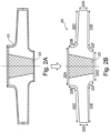
- a metal insert 23 is used for manufacturing a component 20 corresponding to the component 10 of Fig.1 ; it is to be noted that the component 10 and the component 20 have identical or very similar outside surfaces but they have different structure, i.e. are different inside.
- Container 21 is similar to container 11.
- the insert 23 is located inside the container 21 before filling the container 21 with metal powder (see Fig.2A ) and is left in the component 20 after the end of its manufacturing (see Fig.2B ).
- the insert 23 has a shaped that is similar to that of the bulk portion of the component. In this way, it's possible to reduce the space between the container and the insert during the hot isostatic pressing and consequently the thickness of the component in the area next to the insert. Since the thickness of metal in this region of the component is reduced, when the component cools the risk of shrink is reduced.
- the insert 23 of the embodiment of Fig.2 has the shape of a truncated cone and is coaxial with the container 21; it occupies most of the region 19 shown in Fig.1A (which is important), but it extends even beyond the region 19 shown in Fig.1A .
- Other shapes may be possible, for a cone shape, a prism shape, a truncated pyramid shape, a sphere shape, an ellipsoid shape, ....
- the container 11 in Fig.1A and the container 21 in Fig.2A are drawn identical; for the sake of drafting simplicity; anyway, due to the presence of the insert, the two containers may be quite different because their overall deformations during the P/M-HIP process are different even if the component 10 and the component 20 have identical or very similar outside surfaces; in particular, the overall deformation of the container 11 is higher than the overall deformation of the container 21 as the material in the region 19 of the container 11 shrink much more than the corresponding region of the container 21 where there is the insert 23 (whose deformation is typically null or almost null).
- the insert 23 has two surfaces adjacent to the container 21. Therefore, these two surfaces correspond to outside surfaces of the component 20 (see Fig.2B ); specifically, these two surfaces are portions of surfaces 22A and 22G.
- the insert 23 it will be easier to manufacture component 20 by P/M-HIP, without real manufacturing trials, with very accurate surfaces, in particular surfaces 22B and 22F that are close to the insert 23, as well as surfaces 22A and 22G.
- Fig.3B shows a simplified cross-sectional view of a second turbomachine component 30, in particular a closed centrifugal impeller of a centrifugal compressor, that has an axial symmetry (corresponding to the rotation axis)(to be precise it is an antisymmetry) and an axial through hole; this component is manufactured by powder metal hot isostatic pressing, i.e. P/M-HIP.
- Fig.3A shows a container 31 used for manufacturing component 30 by P/M-HIP; according to this technology, the container 31 is filled with metal powder.
- the container 31 defines the outside surfaces of the component 30; in particular, there are a top surface 32A (substantially ring-shaped), an upper vertical surface 32B, an upper horizontal surface 32C, an intermediate vertical surface 32D, a lower horizontal surface 32E, a lower vertical surface 32F, a bottom surface 32G (substantially ring shaped) and an internal vertical surface 32H (that has for example a cylindrical shape and defines the through hole of the component); in this example, the container 31 has a circular through hole, but alternatively it may comprise a fully solid and rigid cylindrical part.
- the component 30 has a plurality of internal flow paths 35; in order to define the surfaces of the plurality of through holes 35 a corresponding plurality of metal cores 34 are located inside the container 31; alternatively, the cores 34 may correspond to the arms of a single body.
- the metal cores are located inside the container 31 before filling the container 31 with metal powder (see Fig.3A ), and are removed from the component 30 before the end of its manufacturing (see Fig.3B ).
- high deformations may be caused for example by region 39 of the container 31 where there is a lot of metal powder (that is subject to high total shrinkage) when the container 31 is filled with powder; in this example, the region 39 has the shape of a ring.
- all the outside surfaces 32A, 32B, 32C, 32D, 32E, 32F, 32G and 32H of the component 30 and all the inside surfaces of the component 30 will have shapes, positions and sizes different from the desired ones; this is particularly disadvantageous for the inside surfaces as accurately machining these surfaces is difficult or, sometimes, even impossible.
- the shapes, positions and sizes of the walls of the container change during the P/M-HIP process; anyway, in Fig.3 , for the sake of drafting simplicity, the shapes, positions and sizes of the internal surfaces of the container 31 before the start of the process correspond to the shapes, positions and sizes of the external surfaces of the component 30 after the end of the process.
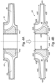
- a metal insert 443 is used for manufacturing a component 40 corresponding to the component 30 of Fig.3 ; it is to be noted that the component 30 and the component 40 have identical or very similar outside surfaces but they have different structure.
- Container 41 is similar to container 31.
- the insert 443 is located inside the container 41 before filling the container 41 with metal powder (see Fig.4A ) and is left in the component 20 after the end of its manufacturing (see Fig.4B ).
- the cores 44 are located inside the container 41 before filling the container 41 with metal powder (see Fig.4A ) and are removed from the component 40 before the end of its manufacturing (see Fig.4B ).
- the insert 443 of the embodiment of Fig.4 has the shape of a ring and is coaxial with the container 41; it occupies most of the region 39 shown in Fig.3A (which is important), but it extends even beyond the region 39 shown in Fig.3A .
- the shape of the cross-section of this ring is such as to occupy most of the space between the flow path cavities and the rotation axis of the component.
- the container 31 in Fig.3A and the container 41 in Fig.4A are drawn identical; for the sake of drafting simplicity; anyway, due to the presence of the insert, the two containers may be quite different because their deformations during the P/M-HIP process are different even if the component 30 and the component 40 have identical or very similar outside surfaces; in particular, the overall deformation of the container 31 is higher than the overall deformation of the container 41 as the material in the region 39 of the container 31 shrink much more than the corresponding region of the container 41 where there is the insert 443 (whose deformation is typically null or almost null).
- the insert 443 has one surface adjacent to the container 41. Therefore, this surface corresponds to an outside surface of the component 40 (see Fig.4B ); specifically, this surface is a portion of surface 42H.
- the insert 443 has no surface adjacent to the core 44 (see Fig.4A ); a surface of the insert 443 is close to the core 44 and substantially parallel.
- the insert 443 it will be easier to manufacture component 40 by P/M-HIP, without real manufacturing trials, with very accurate surfaces, in particular outside surfaces and, even more important, inside surfaces, i.e. the surfaces defining the flow paths 45 (where the cores 44 are located before removal at the end of manufacturing).
- Fig.5 is very similar to the embodiment of Fig.4 .
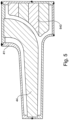
- the metal insert 543 is a bulk insert in a plurality of pieces; each of the pieces is ring-shaped; the pieces are separate and adjacent to each other (i.e. fully in contact) so to form a single body within the metal powder before filling the container; alternatively, for example, the pieces of the insert are separate and (a little) distant from each other so that some metal powder may fill the gap between them and facilitate bonding of these pieces; preferably, the distance is preferably in the range from 0.5 mm to 5.0 mm.
- the container 41 comprises recesses designed to lock the insert 543 and the core 44; specifically, there are a first recess in the top wall and a second recess in an intermediate vertical wall of the container for locking respectively a first and a second end of the core; specifically, there is a third recess in the internal vertical wall of the container for locking and keeping them together the various pieces of the insert.
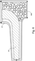
- the metal insert 643 is a bulk insert in a plurality of pieces; the plurality of pieces are separate from each other (even if partially in contact) so to form a plurality of bodies within the metal powder before filling the container.
- the bodies have different shapes of geometric figures an similar size; anyway, there are many other possibilities including for example irregular figures and/or different sizes, such as for example gravel.
- Fig.7 is similar to the embodiment of Fig.4 .
- the difference consists in that the metal insert 743 has a surface adjacent to the core 44.
- the container 41 comprises recesses designed to lock the core 44; specifically, there are a first recess in the top wall and a second recess in an intermediate vertical wall of the container for locking respectively a first and a second end of the core.
- the insert 743 is reasonably locked inside container 41 as it is ring-shaped and it is adjacent to both the cores 44 and a wall of the container 41 (see Fig.7 below) so that it can not move.
- Fig.8 is very similar to the embodiment of Fig.7 .
- the difference consists in that the metal insert 843 has also another surface adjacent to the container.
- the metal material of the insert and the metal material of the powder for the P/M-HIP are the same; in this way, the two parts of the component match and join very well; furthermore, in this way, it is easier to define heat treatments for the component as the same heat treatment would work equally well for both the solid insert and the hot-pressed powder.
- One or more of the surfaces of the insert may have protrusions (e.g. ribs) and/or may be corrugated or textured or rough; if this regards a surface at the interface between the powder and the insert, a better connection between the pressed powder and the insert may be achieved and a more reliable and more strong joint may be obtained.
- protrusions e.g. ribs
- corrugated or textured or rough if this regards a surface at the interface between the powder and the insert, a better connection between the pressed powder and the insert may be achieved and a more reliable and more strong joint may be obtained.
- the insert is preferably fully solid and preferably rigid. It is manufactured before the component, even a long time before. It may be manufactured in different ways: by powder metal hot isostatic pressing, by additive manufacturing, by forging, by casting (for example investment casting), ....
- the container may be removed from the component before the end of its manufacturing, as it is common according to the P/M-HIP technology, and as it is shown in Fig.1 , Fig.2 , Fig.3 , Fig.4 .
- the container is removed by machining (for example turning or milling) and/or by pickling.
- the container may be left, at least partially, in the component after the end of its manufacturing.
- the container is made of carbon steel; if it has to be removed, it may be useful to use low carbon steel in order to facilitate removal.
- the core or cores are removed from the component before the end of its manufacturing.
- the core or cores are removed by machining (for example drilling or milling) and/or by pickling.
- the core or cores are made of carbon steel, preferably low carbon steel in order to facilitate removal.
- the metal insert is locked to the container by means of recesses in an inside wall of the container.
- the insert is locked to the container by means of pins.
- the metal insert has the shape of a ring.
- the insert consists of a plurality (for example two of e.g. 180° or three of e.g. 120° or four of e.g. 90°) sectors adjacent to each other or separate and (a little) distant from each other; furthermore, the sectors may be fixed to each other.
- the metal insert is fully inside the container.
- the insert reach one or more the outside surfaces of the container (and act partially also as a wall of the container).
Landscapes
- Engineering & Computer Science (AREA)
- Mechanical Engineering (AREA)
- Manufacturing & Machinery (AREA)
- Chemical & Material Sciences (AREA)
- Materials Engineering (AREA)
- General Engineering & Computer Science (AREA)
- Composite Materials (AREA)
- Powder Metallurgy (AREA)
- Structures Of Non-Positive Displacement Pumps (AREA)
Description
- Embodiments of the subject matter disclosed herein relate to methods of manufacturing a component of a turbomachine, components of turbomachines and turbomachines.
-
EP 0 629 770 A2 discloses a ring capsule in which fibre reinforced rings are arranged. The ring capsule is filled with metal powder. - One of the technology used for manufacturing components of turbomachines is powder metallurgy hot isostatic pressing, in short P/M-HIP; this technology is used for example for manufacturing closed impellers of centrifugal compressors made of metal material.
- One of the reasons why this technology is attractive is that, through a particular approach, it allows to manufacture metal parts that do not need further machining or need limited amount of machining of the whole part or at least of some surfaces of the part; in this case, the technology is referred to as "Net-Shape HIP"; although this approach may be applied both to external surfaces and internal surfaces of a part, it is particularly useful when applied to the internal surfaces as machining of these surfaces is difficult or, sometimes, even impossible.
- The cost and the time of machining depend on the type of material to be machined, the quantity of material to be removed, the accessibility of the material to be removed, and the machining technology used; for example, milling is relatively quick but a milling tool is (relatively) quite small while Electric Discharge Machining is slower but an EDM tool is (relatively) quite bigger.
- In order to obtain a finished or almost-finished part, i.e. with "net shape surfaces", it is necessary to simulate accurately the behavior of the (metal) container, the (metal) powder and the HIP equipment used for manufacturing the part.
- Furthermore, even if accurate simulations are carried out, some real manufacturing trials (typically one or two or three) are necessary in order to meet the required design dimensional tolerances of complex part; after each trial, the obtained part is checked and measured and some changes are made to the container and/or to the HIP process parameters (for example the pressure curve and/or the temperature curve).
- Therefore, the "net shape surfaces" approach is generally applied only to few specific surfaces and not to all surfaces of a part to be manufactured.
- Simulations and trials impact on the time and the cost necessary for starting the production of a new part and, therefore, are a problem especially for single-part production or small-series production. In the field of oil & gas, there are some parts of some turbomachines that are "single parts"; in other words, such part of a turbomachine is different from any part of any turbomachine that was manufactured in the past and from any part of any turbomachine that will be manufactured in the future, even if such part may be quite similar to the past parts and to the future parts.
- The present invention is defined in the accompanying claims.
- According to the P/M-HIP technology, a container is used for defining the outside surfaces of the component to be manufactured and the container is filled with metal powder, evacuated of the gas present inside and sealed, and then the powder is consolidated by a Hot Isostatic Pressure thermal cycle; usually, the manufacturing process ends with the removal of the container; the "outside surfaces" of a body are those surfaces that delimit the body externally and therefore do not include the surfaces of through holes and of internal cavities.
- The Applicant has used P/M-HIP also for manufacturing parts having one or more internal channels, including internal channels with tight tolerances such as for example working fluid flow paths; for this purpose, one or more cores have been used, in addition to the container, in order to define inside surfaces of the component, i.e. the surfaces defining the channels.
- During a P/M-HIP process, when heat and pressure is applied, not only the metal powder, but also the container and the cores, if any, deform. This leads, for example, to a change in the shape, size and position of any internal channel of the manufactured part.
- The higher the deformations the more manufacturing trials are necessary, as high deformations are difficult to be predicted exactly through simulation.
- The Applicant has thought that if deformations should be sufficiently low, simulations would be necessary but real manufacturing trials would not be necessary; in this way, the time and the cost for starting the production of a new part through P/M-HIP would be reduced considerably.
- The Applicant has considered that the highest deformations are caused by those regions of the container where there is a lot of mass of metal powder that is subject to the highest shrinkage; anyway, in general, deformations can not be reduced by simply changing the shape and size of the container or the shapes and sizes of its regions because these shapes and sizes are strongly related to the shapes and sizes of the part to be manufactured.
- The Applicant has conceived to locate at least one metal insert inside the container before filling the container with metal powder; the metal insert is to be located in a region of the container having a big or the biggest volume, i.e. where a lot of mass of metal powder (that is subject to a high or the highest shrinkage) would locate according to a traditional P/M-HIP process; in general, more than one insert may be used.
- As the metal insert is fully solid, its shrinkage during the P/M-HIP process is much smaller, typically null or almost null, than that of a corresponding mass of metal powder, and this leads to smaller overall deformations and changes in the shape and size of the manufactured part, in particular of its surfaces. According to the present invention, such insert is left in the part after the end of its manufacturing.
- If the part to be manufactured has one or more internal channels, one or more metal cores may be located inside the container before filling the container with metal powder, and the one or more cores are removed from the part before the end of its manufacturing. In this case, also the shape, size and position of the one ore more internal channels, in particular their surfaces, experience small deformations and changes (smaller than those obtained according to the prior art methods).
- First exemplary embodiments relate to methods of manufacturing a component of a turbomachine by powder metal hot isostatic pressing, using a container defining outside surfaces of the component; at least one metal insert is located inside the container before filling the container with metal powder; the insert is left in the component after the end of its manufacturing. According to such embodiments, at least one metal core may be located inside the container before filling the container with metal powder; this core is removed from the component before the end of its manufacturing.
- The present invention will become more apparent from the following description of exemplary embodiments to be considered in conjunction with accompanying drawings wherein:
-
Figure 1 shows a simplified cross-sectional view of a first arrangement (according to the prior art) for manufacturing a first mechanical part by powder metal hot isostatic pressing, and a corresponding turbomachine component; -
Figure 2 shows a simplified cross-sectional view of a second arrangement (according to the present invention) for manufacturing the first mechanical part by powder metal hot isostatic pressing, and a corresponding turbomachine component; -
Figure 3 shows a simplified cross-sectional view of a third arrangement (according to the prior art) for manufacturing a second mechanical part by powder metal hot isostatic pressing, and a corresponding turbomachine component; -
Figure 4 shows a simplified cross-sectional view of a fourth arrangement (according to the present invention) for manufacturing the second mechanical part by powder metal hot isostatic pressing, and a corresponding turbomachine component; -
Figure 5 shows a cross-sectional partial view of a fifth arrangement (according to the present invention) for manufacturing the second mechanical part by powder metal hot isostatic pressing; -
Figure 6 shows a cross-sectional partial view of a sixth arrangement (according to the present invention) for manufacturing the second mechanical part by powder metal hot isostatic pressing; -
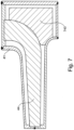
Figure 7 shows a cross-sectional partial view of a seventh arrangement (according to the present invention) for manufacturing the second mechanical part by powder metal hot isostatic pressing; and -
Figure 8 shows a cross-sectional partial view of a eighth arrangement (according to the present invention) for manufacturing the second mechanical part by powder metal hot isostatic pressing. - The following description of exemplary embodiments refer to the accompanying drawings. The same reference numbers in different drawings identify the same or similar elements. The following detailed description does not limit the invention. Instead, the scope of the invention is defined by the appended claims.
- Reference throughout the specification to "one embodiment" or "an embodiment" means that a particular feature, structure, or characteristic described in connection with an embodiment is included in at least one embodiment of the subject matter disclosed. Thus, the appearance of the phrases "in one embodiment" or "in an embodiment" in various places throughout the specification is not necessarily referring to the same embodiment. Further, the particular features, structures or characteristics may be combined in any suitable manner in one or more embodiments.
- In the following exemplary description, it must be assumed that all parts shown in the figures are manufactured by powder metal hot isostatic pressing, i.e. P/M-HIP, even if, sometimes, other technologies might be used.
-
Fig.1B shows a simplified cross-sectional view of afirst turbomachine component 10, in particular a rotor wheel of a turbine, that has an axial symmetry (corresponding to the rotation axis); this component is manufactured by P/M-HIP. -
Fig.1A shows acontainer 11 used formanufacturing component 10 by P/M-HIP; according to this technology, thecontainer 11 is filled with metal powder. Thecontainer 11 defines the outside surfaces of thecomponent 10; in particular, there are atop surface 12A (substantially circular), an uppervertical surface 12B, an upperhorizontal surface 12C, an intermediatevertical surface 12D, a lowerhorizontal surface 12E, a lowervertical surface 12F, abottom surface 12G (substantially circular). - In the example of
Fig.1 , high deformations may be caused for example byregion 19 of thecontainer 11 where there is a lot of metal powder (that is subject to high total shrinkage) when thecontainer 11 is filled with powder; in this example, theregion 19 has the shape of an ellipsoid. This means that without adequate simulations and without real manufacturing trials, all thesurfaces component 10 will have shapes, positions and sizes different from the desired ones. - It is to be noted that the shapes, positions and sizes of the walls of the container change during the P/M-HIP process; anyway, in
Fig.1 , for the sake of drafting simplicity, the shapes, positions and sizes of the internal surfaces of thecontainer 11 before the start of the process correspond to the shapes, positions and sizes of the external surfaces of thecomponent 10 after the end of the process. - According to the teaching of the present invention - see
Fig.2 , ametal insert 23 is used for manufacturing acomponent 20 corresponding to thecomponent 10 ofFig.1 ; it is to be noted that thecomponent 10 and thecomponent 20 have identical or very similar outside surfaces but they have different structure, i.e. are different inside. -
Container 21 is similar tocontainer 11. - The
insert 23 is located inside thecontainer 21 before filling thecontainer 21 with metal powder (seeFig.2A ) and is left in thecomponent 20 after the end of its manufacturing (seeFig.2B ). - The
insert 23 has a shaped that is similar to that of the bulk portion of the component. In this way, it's possible to reduce the space between the container and the insert during the hot isostatic pressing and consequently the thickness of the component in the area next to the insert. Since the thickness of metal in this region of the component is reduced, when the component cools the risk of shrink is reduced. - The
insert 23 of the embodiment ofFig.2 has the shape of a truncated cone and is coaxial with thecontainer 21; it occupies most of theregion 19 shown inFig.1A (which is important), but it extends even beyond theregion 19 shown inFig.1A . Other shapes may be possible, for a cone shape, a prism shape, a truncated pyramid shape, a sphere shape, an ellipsoid shape, .... - It is to be noted that the
container 11 inFig.1A and thecontainer 21 inFig.2A are drawn identical; for the sake of drafting simplicity; anyway, due to the presence of the insert, the two containers may be quite different because their overall deformations during the P/M-HIP process are different even if thecomponent 10 and thecomponent 20 have identical or very similar outside surfaces; in particular, the overall deformation of thecontainer 11 is higher than the overall deformation of thecontainer 21 as the material in theregion 19 of thecontainer 11 shrink much more than the corresponding region of thecontainer 21 where there is the insert 23 (whose deformation is typically null or almost null). - In the embodiment of
Fig.2 , theinsert 23 has two surfaces adjacent to thecontainer 21. Therefore, these two surfaces correspond to outside surfaces of the component 20 (seeFig.2B ); specifically, these two surfaces are portions ofsurfaces - Thanks to the
insert 23, it will be easier to manufacturecomponent 20 by P/M-HIP, without real manufacturing trials, with very accurate surfaces, inparticular surfaces insert 23, as well assurfaces -
Fig.3B shows a simplified cross-sectional view of asecond turbomachine component 30, in particular a closed centrifugal impeller of a centrifugal compressor, that has an axial symmetry (corresponding to the rotation axis)(to be precise it is an antisymmetry) and an axial through hole; this component is manufactured by powder metal hot isostatic pressing, i.e. P/M-HIP. -
Fig.3A shows acontainer 31 used formanufacturing component 30 by P/M-HIP; according to this technology, thecontainer 31 is filled with metal powder. Thecontainer 31 defines the outside surfaces of thecomponent 30; in particular, there are atop surface 32A (substantially ring-shaped), an uppervertical surface 32B, an upperhorizontal surface 32C, an intermediatevertical surface 32D, a lowerhorizontal surface 32E, a lowervertical surface 32F, abottom surface 32G (substantially ring shaped) and an internalvertical surface 32H (that has for example a cylindrical shape and defines the through hole of the component); in this example, thecontainer 31 has a circular through hole, but alternatively it may comprise a fully solid and rigid cylindrical part. - Furthermore, the
component 30 has a plurality ofinternal flow paths 35; in order to define the surfaces of the plurality of through holes 35 a corresponding plurality ofmetal cores 34 are located inside thecontainer 31; alternatively, thecores 34 may correspond to the arms of a single body. The metal cores are located inside thecontainer 31 before filling thecontainer 31 with metal powder (seeFig.3A ), and are removed from thecomponent 30 before the end of its manufacturing (seeFig.3B ). - In the example of
Fig.3 , high deformations may be caused for example byregion 39 of thecontainer 31 where there is a lot of metal powder (that is subject to high total shrinkage) when thecontainer 31 is filled with powder; in this example, theregion 39 has the shape of a ring. This means that without adequate simulations and without real manufacturing trials, all theoutside surfaces component 30 and all the inside surfaces of the component 30 (i.e. the surfaces defining the internal paths 35) will have shapes, positions and sizes different from the desired ones; this is particularly disadvantageous for the inside surfaces as accurately machining these surfaces is difficult or, sometimes, even impossible. - It is to be noted that the shapes, positions and sizes of the walls of the container change during the P/M-HIP process; anyway, in
Fig.3 , for the sake of drafting simplicity, the shapes, positions and sizes of the internal surfaces of thecontainer 31 before the start of the process correspond to the shapes, positions and sizes of the external surfaces of thecomponent 30 after the end of the process. - According to the teaching of the present invention - see
Fig.4 , ametal insert 443 is used for manufacturing acomponent 40 corresponding to thecomponent 30 ofFig.3 ; it is to be noted that thecomponent 30 and thecomponent 40 have identical or very similar outside surfaces but they have different structure. -
Container 41 is similar tocontainer 31. - The
insert 443 is located inside thecontainer 41 before filling thecontainer 41 with metal powder (seeFig.4A ) and is left in thecomponent 20 after the end of its manufacturing (seeFig.4B ). - The
cores 44 are located inside thecontainer 41 before filling thecontainer 41 with metal powder (seeFig.4A ) and are removed from thecomponent 40 before the end of its manufacturing (seeFig.4B ). - The
insert 443 of the embodiment ofFig.4 has the shape of a ring and is coaxial with thecontainer 41; it occupies most of theregion 39 shown inFig.3A (which is important), but it extends even beyond theregion 39 shown inFig.3A . The shape of the cross-section of this ring is such as to occupy most of the space between the flow path cavities and the rotation axis of the component. - It is to be noted that the
container 31 inFig.3A and thecontainer 41 inFig.4A are drawn identical; for the sake of drafting simplicity; anyway, due to the presence of the insert, the two containers may be quite different because their deformations during the P/M-HIP process are different even if thecomponent 30 and thecomponent 40 have identical or very similar outside surfaces; in particular, the overall deformation of thecontainer 31 is higher than the overall deformation of thecontainer 41 as the material in theregion 39 of thecontainer 31 shrink much more than the corresponding region of thecontainer 41 where there is the insert 443 (whose deformation is typically null or almost null). - In the embodiment of
Fig.4 , only one insert is provided and is a bulk insert in a single piece. - In the embodiment of
Fig.4 , theinsert 443 has one surface adjacent to thecontainer 41. Therefore, this surface corresponds to an outside surface of the component 40 (seeFig.4B ); specifically, this surface is a portion ofsurface 42H. - In the embodiment of
Fig.4 , theinsert 443 has no surface adjacent to the core 44 (seeFig.4A ); a surface of theinsert 443 is close to thecore 44 and substantially parallel. - Thanks to the
insert 443, it will be easier to manufacturecomponent 40 by P/M-HIP, without real manufacturing trials, with very accurate surfaces, in particular outside surfaces and, even more important, inside surfaces, i.e. the surfaces defining the flow paths 45 (where thecores 44 are located before removal at the end of manufacturing). - The embodiment of
Fig.5 is very similar to the embodiment ofFig.4 . - The difference consists in that the
metal insert 543 is a bulk insert in a plurality of pieces; each of the pieces is ring-shaped; the pieces are separate and adjacent to each other (i.e. fully in contact) so to form a single body within the metal powder before filling the container; alternatively, for example, the pieces of the insert are separate and (a little) distant from each other so that some metal powder may fill the gap between them and facilitate bonding of these pieces; preferably, the distance is preferably in the range from 0.5 mm to 5.0 mm. - As
Fig.5 is an enlarged view, it is possible to see more details of thecontainer 41. For example thecontainer 41 comprises recesses designed to lock theinsert 543 and thecore 44; specifically, there are a first recess in the top wall and a second recess in an intermediate vertical wall of the container for locking respectively a first and a second end of the core; specifically, there is a third recess in the internal vertical wall of the container for locking and keeping them together the various pieces of the insert. - In the embodiment of
Fig.6 , themetal insert 643 is a bulk insert in a plurality of pieces; the plurality of pieces are separate from each other (even if partially in contact) so to form a plurality of bodies within the metal powder before filling the container. InFig.6 , the bodies have different shapes of geometric figures an similar size; anyway, there are many other possibilities including for example irregular figures and/or different sizes, such as for example gravel. - The embodiment of
Fig.7 is similar to the embodiment ofFig.4 . - The difference consists in that the
metal insert 743 has a surface adjacent to thecore 44. - As
Fig.7 is an enlarged view, it is possible to see more details of thecontainer 41. For example thecontainer 41 comprises recesses designed to lock thecore 44; specifically, there are a first recess in the top wall and a second recess in an intermediate vertical wall of the container for locking respectively a first and a second end of the core. - The
insert 743 is reasonably locked insidecontainer 41 as it is ring-shaped and it is adjacent to both thecores 44 and a wall of the container 41 (seeFig.7 below) so that it can not move. - The embodiment of
Fig.8 is very similar to the embodiment ofFig.7 . - The difference consists in that the
metal insert 843 has also another surface adjacent to the container. - Specifically, there is a recess in the internal vertical wall of the container for locking, even better, the
insert 843. - Preferably, the metal material of the insert and the metal material of the powder for the P/M-HIP are the same; in this way, the two parts of the component match and join very well; furthermore, in this way, it is easier to define heat treatments for the component as the same heat treatment would work equally well for both the solid insert and the hot-pressed powder.
- In principle, different materials may also be used for the insert and the powder.
- One or more of the surfaces of the insert may have protrusions (e.g. ribs) and/or may be corrugated or textured or rough; if this regards a surface at the interface between the powder and the insert, a better connection between the pressed powder and the insert may be achieved and a more reliable and more strong joint may be obtained.
- The insert is preferably fully solid and preferably rigid. It is manufactured before the component, even a long time before. It may be manufactured in different ways: by powder metal hot isostatic pressing, by additive manufacturing, by forging, by casting (for example investment casting), ....
- The container may be removed from the component before the end of its manufacturing, as it is common according to the P/M-HIP technology, and as it is shown in
Fig.1 ,Fig.2 ,Fig.3 ,Fig.4 . Usually, the container is removed by machining (for example turning or milling) and/or by pickling. - Alternatively, the container may be left, at least partially, in the component after the end of its manufacturing.
- Usually, the container is made of carbon steel; if it has to be removed, it may be useful to use low carbon steel in order to facilitate removal.
- As already said, the core or cores, if any, are removed from the component before the end of its manufacturing. Usually, the core or cores are removed by machining (for example drilling or milling) and/or by pickling. Usually, the core or cores are made of carbon steel, preferably low carbon steel in order to facilitate removal.
- In some of the embodiments shown in the annexed figures, the metal insert is locked to the container by means of recesses in an inside wall of the container. Anyway, according to alternative embodiments, the insert is locked to the container by means of pins.
- In all the embodiments shown in the annexed figures, the metal insert has the shape of a ring. Anyway, according to alternative embodiments, the insert consists of a plurality (for example two of e.g. 180° or three of e.g. 120° or four of e.g. 90°) sectors adjacent to each other or separate and (a little) distant from each other; furthermore, the sectors may be fixed to each other.
- In all the embodiments shown in the annexed figures, the metal insert is fully inside the container. Anyway, according to alternative embodiments, the insert reach one or more the outside surfaces of the container (and act partially also as a wall of the container).
Claims (10)
- A method of manufacturing a component (20; 40) of a turbomachine by powder metal hot isostatic pressing, using a container (21; 41) defining outside surfaces (22A, 22B, 22C, 22D, 22E, 22F, 22G; 42A, 42B, 42C, 42D, 42E, 42F, 42G, 42H) of the component (20; 40);wherein a metal insert (23; 443; 543; 643; 743; 843) and a metal core (44) are located inside the container (21; 41) before filling the container (21; 41) with metal powder, the metal material of the insert and the metal material of the powder being the same; andwherein the insert (23; 443; 543; 643; 743; 843) is left in the component (20;40) after the end of its manufacturing, and the core (44) is removed from the component (20; 40) before the end of its manufacturing by pickling and/or by machining.
- The method of claim 1, wherein the container (21; 41) is removed from the component (20; 40) before the end of its manufacturing or is left, at least partially, in the component (20; 40) after the end of its manufacturing.
- The method of claim 1 or claim 2, wherein the insert (23; 443; 543; 643; 743; 843) is a bulk insert in a single piece (23; 443; 743; 843) or in a plurality of pieces (543; 643).
- The method of claim 3, wherein the plurality of pieces are separate, in contact and adjacent to each other so to form a single body (543) within the metal powder before filling the container (21; 41).
- The method of claim 3, wherein the plurality of pieces are separate and in contact with each other so to form a plurality of bodies (643) within the metal powder before filling the container (21; 41).
- The method of claim 3, wherein the pieces are distant from each other so that metal powder may interpose, the distance being preferably in the range from 0.5 mm to 5.0 mm.
- The method of any of the preceding claims from 1 to 6, wherein the insert (23; 443; 543; 843) has at least one surface adjacent to the container (21; 41).
- The method of any of the preceding claims from 1 to 6, wherein the insert (743; 843) has at least one surface adjacent to the core (44).
- The method of any of the preceding claims from 1 to 6, wherein the insert (843) has at least one surface adjacent to the container (41) and at least one surface adjacent to the core (44).
- The method of any of the preceding claims from 1 to 9, wherein the insert (23; 443; 543; 643; 743; 843) is manufactured by powder metal hot isostatic pressing, additive manufacturing, forging or casting.
Applications Claiming Priority (2)
| Application Number | Priority Date | Filing Date | Title |
|---|---|---|---|
| ITCO20140017 | 2014-05-30 | ||
| PCT/EP2015/061903 WO2015181328A1 (en) | 2014-05-30 | 2015-05-28 | Method of manufacturing a component of a turbomachine, component of turbomachine and turbomachine |
Publications (2)
| Publication Number | Publication Date |
|---|---|
| EP3148733A1 EP3148733A1 (en) | 2017-04-05 |
| EP3148733B1 true EP3148733B1 (en) | 2023-11-01 |
Family
ID=51398675
Family Applications (1)
| Application Number | Title | Priority Date | Filing Date |
|---|---|---|---|
| EP15726120.7A Active EP3148733B1 (en) | 2014-05-30 | 2015-05-28 | Method of manufacturing a component of a turbomachine |
Country Status (6)
| Country | Link |
|---|---|
| US (1) | US20170241429A1 (en) |
| EP (1) | EP3148733B1 (en) |
| JP (1) | JP6691486B2 (en) |
| CN (1) | CN106660125B (en) |
| DK (1) | DK3148733T3 (en) |
| WO (1) | WO2015181328A1 (en) |
Families Citing this family (10)
| Publication number | Priority date | Publication date | Assignee | Title |
|---|---|---|---|---|
| GB201700614D0 (en) * | 2017-01-13 | 2017-03-01 | Rolls Royce Plc | A method of manufacturing a component |
| GB2562533B (en) * | 2017-05-19 | 2021-11-17 | Bodycote H I P Ltd | Components |
| EP3486029A1 (en) * | 2017-11-20 | 2019-05-22 | HIPtec AS | A method for manufacturing a metal based frame, and a metal based frame |
| FR3076750B1 (en) * | 2018-01-18 | 2020-06-05 | Safran Power Units | METHOD FOR MANUFACTURING A WHEEL FOR A TURBOMACHINE |
| US11420262B2 (en) * | 2018-01-31 | 2022-08-23 | Divergent Technologies, Inc. | Systems and methods for co-casting of additively manufactured interface nodes |
| DE102018102903A1 (en) * | 2018-02-09 | 2019-08-14 | Otto Fuchs - Kommanditgesellschaft - | Method for producing a structural component from a high-strength alloy material |
| CN110947970B (en) * | 2019-12-05 | 2022-03-15 | 中国航发北京航空材料研究院 | Near-net forming method for thin-wall complex component |
| US11813672B2 (en) | 2020-05-08 | 2023-11-14 | Grid Logic Incorporated | System and method for manufacturing a part |
| KR20240160107A (en) * | 2022-03-04 | 2024-11-08 | 크라이오스타 에스아에스 | Method of manufacturing an impeller |
| WO2024092114A1 (en) * | 2022-10-28 | 2024-05-02 | Grid Logic Incorporated | Additive manufacturing hot-isostatic press process for manufacturing a part |
Citations (1)
| Publication number | Priority date | Publication date | Assignee | Title |
|---|---|---|---|---|
| WO2011121186A1 (en) * | 2010-03-31 | 2011-10-06 | Metso Minerals, Inc. | A method and arrangement for manufacturing a component with hot isostatic pressing, a core, a preform for a cladding, and use of the core |
Family Cites Families (29)
| Publication number | Priority date | Publication date | Assignee | Title |
|---|---|---|---|---|
| JPS4946648B2 (en) * | 1971-10-28 | 1974-12-11 | ||
| US4063939A (en) * | 1975-06-27 | 1977-12-20 | Special Metals Corporation | Composite turbine wheel and process for making same |
| DE3032593A1 (en) * | 1979-09-18 | 1981-04-02 | General Motors Corp., Detroit, Mich. | Composite turbine rotor with radial blades |
| DE3205158C1 (en) * | 1982-02-13 | 1983-08-25 | MTU Motoren- und Turbinen-Union München GmbH, 8000 München | Capsule for hot isostatic pressing of highly stressed and complex shaped workpieces for turbomachinery |
| JPS62120404A (en) * | 1985-11-20 | 1987-06-01 | Toshiba Mach Co Ltd | Coating method for wear-resistant member |
| JPS634005A (en) * | 1986-06-20 | 1988-01-09 | Kobe Steel Ltd | Production of composite radial turbine |
| JPH02263903A (en) * | 1989-04-04 | 1990-10-26 | Kobe Steel Ltd | Manufacture of combined cylinder |
| SE463702B (en) * | 1989-06-01 | 1991-01-14 | Abb Stal Ab | SET TO MAKE A SHARED CIRCULAR RING |
| JPH0598316A (en) * | 1991-10-03 | 1993-04-20 | Kobe Steel Ltd | Production of superalloy composite |
| DE4319727C2 (en) * | 1993-06-15 | 1996-08-29 | Mtu Muenchen Gmbh | Method for producing a blade ring for a rotor constructed like a drum, in particular a compressor rotor of a turbomachine |
| US6114048A (en) * | 1998-09-04 | 2000-09-05 | Brush Wellman, Inc. | Functionally graded metal substrates and process for making same |
| US6210633B1 (en) * | 1999-03-01 | 2001-04-03 | Laboratory Of New Technologies | Method of manufacturing articles of complex shape using powder materials, and apparatus for implementing this method |
| CN100579690C (en) * | 2002-10-07 | 2010-01-13 | 曼B与W狄赛尔公司 | Method and nozzle for manufacturing fuel valve in diesel engine |
| US6939508B2 (en) * | 2002-10-24 | 2005-09-06 | The Boeing Company | Method of manufacturing net-shaped bimetallic parts |
| FR2871398B1 (en) * | 2004-06-15 | 2006-09-29 | Snecma Moteurs Sa | METHOD FOR MANUFACTURING A TURBINE STATOR CASTER |
| US7560065B2 (en) * | 2004-10-08 | 2009-07-14 | Igor Troitski | Method and system for manufacturing of multi-component complex shape parts consisting of monolithic and powder materials working at different performance conditions |
| GB0515211D0 (en) * | 2005-07-23 | 2005-08-31 | Rolls Royce Plc | A method of making titanium components |
| US7413403B2 (en) * | 2005-12-22 | 2008-08-19 | United Technologies Corporation | Turbine blade tip cooling |
| GB0610468D0 (en) * | 2006-05-26 | 2006-07-05 | Rolls Royce Plc | A method of manufacturing a component |
| US9114488B2 (en) * | 2006-11-21 | 2015-08-25 | Honeywell International Inc. | Superalloy rotor component and method of fabrication |
| CN100513018C (en) * | 2007-07-12 | 2009-07-15 | 深圳大学 | Process of making reinforced fast powder metallurgy mold |
| US8128865B2 (en) * | 2007-10-31 | 2012-03-06 | Solar Turbines Inc. | Process of making a shrouded impeller |
| FR2925897B1 (en) * | 2007-12-28 | 2010-07-30 | Messier Dowty Sa | METHOD FOR MANUFACTURING PIECES WITH INSERT IN METALLIC MATRIX COMPOSITE MATERIAL |
| US8951466B2 (en) * | 2009-01-26 | 2015-02-10 | GM Global Technology Operations LLC | Method of making component shapes having non-round exterior shapes |
| DK2236229T3 (en) * | 2009-04-02 | 2015-10-05 | Sandvik Intellectual Property | A process for preparing a powder-based article |
| IT1399883B1 (en) * | 2010-05-18 | 2013-05-09 | Nuova Pignone S R L | INCAMICIATA IMPELLER WITH GRADUATED FUNCTIONAL MATERIAL AND METHOD |
| CN101954481B (en) * | 2010-07-07 | 2012-08-08 | 航天材料及工艺研究所 | Titanium alloy rotor near-net manufacturing method |
| FR2970266B1 (en) * | 2011-01-10 | 2013-12-06 | Snecma | METHOD FOR MANUFACTURING A MONOBLOC ANNULAR METAL PIECE WITH A REINFORCING INSERT IN COMPOSITE MATERIAL, AND PART OBTAINED |
| CN103273064A (en) * | 2013-04-22 | 2013-09-04 | 北京航空航天大学 | Hot isostatic pressure forming method for preparing blisk through overall form-following sheath |
-
2015
- 2015-05-28 CN CN201580028922.6A patent/CN106660125B/en active Active
- 2015-05-28 EP EP15726120.7A patent/EP3148733B1/en active Active
- 2015-05-28 WO PCT/EP2015/061903 patent/WO2015181328A1/en not_active Ceased
- 2015-05-28 US US15/314,953 patent/US20170241429A1/en not_active Abandoned
- 2015-05-28 JP JP2016569385A patent/JP6691486B2/en not_active Expired - Fee Related
- 2015-05-28 DK DK15726120.7T patent/DK3148733T3/en active
Patent Citations (1)
| Publication number | Priority date | Publication date | Assignee | Title |
|---|---|---|---|---|
| WO2011121186A1 (en) * | 2010-03-31 | 2011-10-06 | Metso Minerals, Inc. | A method and arrangement for manufacturing a component with hot isostatic pressing, a core, a preform for a cladding, and use of the core |
Also Published As
| Publication number | Publication date |
|---|---|
| CN106660125A (en) | 2017-05-10 |
| EP3148733A1 (en) | 2017-04-05 |
| JP6691486B2 (en) | 2020-04-28 |
| JP2017517635A (en) | 2017-06-29 |
| US20170241429A1 (en) | 2017-08-24 |
| DK3148733T3 (en) | 2024-01-02 |
| CN106660125B (en) | 2023-03-17 |
| WO2015181328A1 (en) | 2015-12-03 |
Similar Documents
| Publication | Publication Date | Title |
|---|---|---|
| US20170241429A1 (en) | Method of manufacturing a component of a turbomachine, component of turbomachine and turbomachine | |
| RU2733502C2 (en) | Method of making rotary machine component and component made using said method | |
| JP6673781B2 (en) | Mold for powder molding and method for producing green compact | |
| US20130052074A1 (en) | Manufacturing of turbine shroud segment with internal cooling passages | |
| CN104533780B (en) | Hydraulic pump plunger and sliding shoe assembly and machining method thereof | |
| KR20140018632A (en) | Method for manufacturing a impeller and method for manufacturing a turbine wheel | |
| CN104179675A (en) | Fluid end having spherical cross-bore intersection | |
| US20170232506A1 (en) | Die cast system with ceramic casting mold for forming a component usable in a gas turbine engine | |
| WO2017024989A1 (en) | Designing and manufacturing method for powder injection molding piston ring | |
| JP2022185044A (en) | Method for manufacturing metal alloy parts having complex shapes | |
| RU2659520C2 (en) | Method of manufacturing of at least one metal part of the turbo machine | |
| CN103335018A (en) | Inner-ring small-flange separation type conical roller bearing and assembling method thereof | |
| JP2018506671A (en) | Method for manufacturing a turbine engine blade including a tip provided with a complex well | |
| US10081052B2 (en) | Casting of engine parts | |
| US10543523B2 (en) | Forging tool for the manufacturing of a shaped rolled ring, notably for the manufacture of a turbomachine disc | |
| US20120285652A1 (en) | Liner for a Die Body | |
| CN105033258A (en) | Method for producing assembly | |
| KR20170015020A (en) | Mold for motor rotor die casting | |
| JP6347410B2 (en) | Hot forging method for disc-shaped materials | |
| US20180200799A1 (en) | Method of manufacturing a component | |
| CN210498246U (en) | Wax mould of precision casting of inner mesh sleeve pipe | |
| CN104924530B (en) | A kind of plastic compression mould for miniature electronic fuse part | |
| CN203023435U (en) | Pin tooth shell and cycloid reducer comprising same | |
| CN223129361U (en) | A size control device for near-net forming of ring parts by hot isostatic pressing | |
| CN109175186A (en) | A kind of method that molding die and processing bolt are used in interior hexagonal cylindrical headdress flower tooth bolt flower tooth processing |
Legal Events
| Date | Code | Title | Description |
|---|---|---|---|
| STAA | Information on the status of an ep patent application or granted ep patent |
Free format text: STATUS: THE INTERNATIONAL PUBLICATION HAS BEEN MADE |
|
| PUAI | Public reference made under article 153(3) epc to a published international application that has entered the european phase |
Free format text: ORIGINAL CODE: 0009012 |
|
| STAA | Information on the status of an ep patent application or granted ep patent |
Free format text: STATUS: REQUEST FOR EXAMINATION WAS MADE |
|
| 17P | Request for examination filed |
Effective date: 20170102 |
|
| AK | Designated contracting states |
Kind code of ref document: A1 Designated state(s): AL AT BE BG CH CY CZ DE DK EE ES FI FR GB GR HR HU IE IS IT LI LT LU LV MC MK MT NL NO PL PT RO RS SE SI SK SM TR |
|
| AX | Request for extension of the european patent |
Extension state: BA ME |
|
| DAV | Request for validation of the european patent (deleted) | ||
| DAX | Request for extension of the european patent (deleted) | ||
| STAA | Information on the status of an ep patent application or granted ep patent |
Free format text: STATUS: EXAMINATION IS IN PROGRESS |
|
| 17Q | First examination report despatched |
Effective date: 20180111 |
|
| RIC1 | Information provided on ipc code assigned before grant |
Ipc: B22F 3/15 20060101AFI20191219BHEP Ipc: B22F 5/00 20060101ALI20191219BHEP Ipc: B22F 7/08 20060101ALI20191219BHEP Ipc: B22D 25/02 20060101ALI20191219BHEP Ipc: B22F 7/06 20060101ALI20191219BHEP Ipc: F04D 29/28 20060101ALI20191219BHEP Ipc: F04D 29/02 20060101ALI20191219BHEP |
|
| RAP1 | Party data changed (applicant data changed or rights of an application transferred) |
Owner name: NUOVO PIGNONE TECNOLOGIE - S.R.L. |
|
| GRAP | Despatch of communication of intention to grant a patent |
Free format text: ORIGINAL CODE: EPIDOSNIGR1 |
|
| STAA | Information on the status of an ep patent application or granted ep patent |
Free format text: STATUS: GRANT OF PATENT IS INTENDED |
|
| P01 | Opt-out of the competence of the unified patent court (upc) registered |
Effective date: 20230526 |
|
| INTG | Intention to grant announced |
Effective date: 20230620 |
|
| RIN1 | Information on inventor provided before grant (corrected) |
Inventor name: IOZZELLI, FEDERICO Inventor name: CAPPUCCINI, FILIPPO Inventor name: BELLACCI, MICHELANGELO Inventor name: MASI, GABRIELE |
|
| GRAS | Grant fee paid |
Free format text: ORIGINAL CODE: EPIDOSNIGR3 |
|
| GRAA | (expected) grant |
Free format text: ORIGINAL CODE: 0009210 |
|
| STAA | Information on the status of an ep patent application or granted ep patent |
Free format text: STATUS: THE PATENT HAS BEEN GRANTED |
|
| AK | Designated contracting states |
Kind code of ref document: B1 Designated state(s): AL AT BE BG CH CY CZ DE DK EE ES FI FR GB GR HR HU IE IS IT LI LT LU LV MC MK MT NL NO PL PT RO RS SE SI SK SM TR |
|
| REG | Reference to a national code |
Ref country code: GB Ref legal event code: FG4D |
|
| REG | Reference to a national code |
Ref country code: CH Ref legal event code: EP |
|
| REG | Reference to a national code |
Ref country code: IE Ref legal event code: FG4D |
|
| REG | Reference to a national code |
Ref country code: DE Ref legal event code: R096 Ref document number: 602015086329 Country of ref document: DE |
|
| REG | Reference to a national code |
Ref country code: DK Ref legal event code: T3 Effective date: 20231218 |
|
| REG | Reference to a national code |
Ref country code: NL Ref legal event code: FP |
|
| REG | Reference to a national code |
Ref country code: NO Ref legal event code: T2 Effective date: 20231101 |
|
| REG | Reference to a national code |
Ref country code: LT Ref legal event code: MG9D |
|
| PG25 | Lapsed in a contracting state [announced via postgrant information from national office to epo] |
Ref country code: GR Free format text: LAPSE BECAUSE OF FAILURE TO SUBMIT A TRANSLATION OF THE DESCRIPTION OR TO PAY THE FEE WITHIN THE PRESCRIBED TIME-LIMIT Effective date: 20240202 |
|
| PG25 | Lapsed in a contracting state [announced via postgrant information from national office to epo] |
Ref country code: IS Free format text: LAPSE BECAUSE OF FAILURE TO SUBMIT A TRANSLATION OF THE DESCRIPTION OR TO PAY THE FEE WITHIN THE PRESCRIBED TIME-LIMIT Effective date: 20240301 |
|
| PG25 | Lapsed in a contracting state [announced via postgrant information from national office to epo] |
Ref country code: LT Free format text: LAPSE BECAUSE OF FAILURE TO SUBMIT A TRANSLATION OF THE DESCRIPTION OR TO PAY THE FEE WITHIN THE PRESCRIBED TIME-LIMIT Effective date: 20231101 |
|
| REG | Reference to a national code |
Ref country code: AT Ref legal event code: MK05 Ref document number: 1626633 Country of ref document: AT Kind code of ref document: T Effective date: 20231101 |
|
| PG25 | Lapsed in a contracting state [announced via postgrant information from national office to epo] |
Ref country code: AT Free format text: LAPSE BECAUSE OF FAILURE TO SUBMIT A TRANSLATION OF THE DESCRIPTION OR TO PAY THE FEE WITHIN THE PRESCRIBED TIME-LIMIT Effective date: 20231101 |
|
| PG25 | Lapsed in a contracting state [announced via postgrant information from national office to epo] |
Ref country code: ES Free format text: LAPSE BECAUSE OF FAILURE TO SUBMIT A TRANSLATION OF THE DESCRIPTION OR TO PAY THE FEE WITHIN THE PRESCRIBED TIME-LIMIT Effective date: 20231101 |
|
| PG25 | Lapsed in a contracting state [announced via postgrant information from national office to epo] |
Ref country code: LT Free format text: LAPSE BECAUSE OF FAILURE TO SUBMIT A TRANSLATION OF THE DESCRIPTION OR TO PAY THE FEE WITHIN THE PRESCRIBED TIME-LIMIT Effective date: 20231101 Ref country code: IS Free format text: LAPSE BECAUSE OF FAILURE TO SUBMIT A TRANSLATION OF THE DESCRIPTION OR TO PAY THE FEE WITHIN THE PRESCRIBED TIME-LIMIT Effective date: 20240301 Ref country code: GR Free format text: LAPSE BECAUSE OF FAILURE TO SUBMIT A TRANSLATION OF THE DESCRIPTION OR TO PAY THE FEE WITHIN THE PRESCRIBED TIME-LIMIT Effective date: 20240202 Ref country code: ES Free format text: LAPSE BECAUSE OF FAILURE TO SUBMIT A TRANSLATION OF THE DESCRIPTION OR TO PAY THE FEE WITHIN THE PRESCRIBED TIME-LIMIT Effective date: 20231101 Ref country code: BG Free format text: LAPSE BECAUSE OF FAILURE TO SUBMIT A TRANSLATION OF THE DESCRIPTION OR TO PAY THE FEE WITHIN THE PRESCRIBED TIME-LIMIT Effective date: 20240201 Ref country code: AT Free format text: LAPSE BECAUSE OF FAILURE TO SUBMIT A TRANSLATION OF THE DESCRIPTION OR TO PAY THE FEE WITHIN THE PRESCRIBED TIME-LIMIT Effective date: 20231101 Ref country code: PT Free format text: LAPSE BECAUSE OF FAILURE TO SUBMIT A TRANSLATION OF THE DESCRIPTION OR TO PAY THE FEE WITHIN THE PRESCRIBED TIME-LIMIT Effective date: 20240301 |
|
| PG25 | Lapsed in a contracting state [announced via postgrant information from national office to epo] |
Ref country code: SE Free format text: LAPSE BECAUSE OF FAILURE TO SUBMIT A TRANSLATION OF THE DESCRIPTION OR TO PAY THE FEE WITHIN THE PRESCRIBED TIME-LIMIT Effective date: 20231101 Ref country code: RS Free format text: LAPSE BECAUSE OF FAILURE TO SUBMIT A TRANSLATION OF THE DESCRIPTION OR TO PAY THE FEE WITHIN THE PRESCRIBED TIME-LIMIT Effective date: 20231101 Ref country code: PL Free format text: LAPSE BECAUSE OF FAILURE TO SUBMIT A TRANSLATION OF THE DESCRIPTION OR TO PAY THE FEE WITHIN THE PRESCRIBED TIME-LIMIT Effective date: 20231101 Ref country code: LV Free format text: LAPSE BECAUSE OF FAILURE TO SUBMIT A TRANSLATION OF THE DESCRIPTION OR TO PAY THE FEE WITHIN THE PRESCRIBED TIME-LIMIT Effective date: 20231101 Ref country code: HR Free format text: LAPSE BECAUSE OF FAILURE TO SUBMIT A TRANSLATION OF THE DESCRIPTION OR TO PAY THE FEE WITHIN THE PRESCRIBED TIME-LIMIT Effective date: 20231101 |
|
| PG25 | Lapsed in a contracting state [announced via postgrant information from national office to epo] |
Ref country code: CZ Free format text: LAPSE BECAUSE OF FAILURE TO SUBMIT A TRANSLATION OF THE DESCRIPTION OR TO PAY THE FEE WITHIN THE PRESCRIBED TIME-LIMIT Effective date: 20231101 |
|
| PG25 | Lapsed in a contracting state [announced via postgrant information from national office to epo] |
Ref country code: SK Free format text: LAPSE BECAUSE OF FAILURE TO SUBMIT A TRANSLATION OF THE DESCRIPTION OR TO PAY THE FEE WITHIN THE PRESCRIBED TIME-LIMIT Effective date: 20231101 |
|
| PG25 | Lapsed in a contracting state [announced via postgrant information from national office to epo] |
Ref country code: SM Free format text: LAPSE BECAUSE OF FAILURE TO SUBMIT A TRANSLATION OF THE DESCRIPTION OR TO PAY THE FEE WITHIN THE PRESCRIBED TIME-LIMIT Effective date: 20231101 Ref country code: SK Free format text: LAPSE BECAUSE OF FAILURE TO SUBMIT A TRANSLATION OF THE DESCRIPTION OR TO PAY THE FEE WITHIN THE PRESCRIBED TIME-LIMIT Effective date: 20231101 Ref country code: RO Free format text: LAPSE BECAUSE OF FAILURE TO SUBMIT A TRANSLATION OF THE DESCRIPTION OR TO PAY THE FEE WITHIN THE PRESCRIBED TIME-LIMIT Effective date: 20231101 Ref country code: IT Free format text: LAPSE BECAUSE OF FAILURE TO SUBMIT A TRANSLATION OF THE DESCRIPTION OR TO PAY THE FEE WITHIN THE PRESCRIBED TIME-LIMIT Effective date: 20231101 Ref country code: EE Free format text: LAPSE BECAUSE OF FAILURE TO SUBMIT A TRANSLATION OF THE DESCRIPTION OR TO PAY THE FEE WITHIN THE PRESCRIBED TIME-LIMIT Effective date: 20231101 Ref country code: CZ Free format text: LAPSE BECAUSE OF FAILURE TO SUBMIT A TRANSLATION OF THE DESCRIPTION OR TO PAY THE FEE WITHIN THE PRESCRIBED TIME-LIMIT Effective date: 20231101 |
|
| REG | Reference to a national code |
Ref country code: DE Ref legal event code: R097 Ref document number: 602015086329 Country of ref document: DE |
|
| PLBE | No opposition filed within time limit |
Free format text: ORIGINAL CODE: 0009261 |
|
| STAA | Information on the status of an ep patent application or granted ep patent |
Free format text: STATUS: NO OPPOSITION FILED WITHIN TIME LIMIT |
|
| 26N | No opposition filed |
Effective date: 20240802 |
|
| PG25 | Lapsed in a contracting state [announced via postgrant information from national office to epo] |
Ref country code: SI Free format text: LAPSE BECAUSE OF FAILURE TO SUBMIT A TRANSLATION OF THE DESCRIPTION OR TO PAY THE FEE WITHIN THE PRESCRIBED TIME-LIMIT Effective date: 20231101 |
|
| PG25 | Lapsed in a contracting state [announced via postgrant information from national office to epo] |
Ref country code: SI Free format text: LAPSE BECAUSE OF FAILURE TO SUBMIT A TRANSLATION OF THE DESCRIPTION OR TO PAY THE FEE WITHIN THE PRESCRIBED TIME-LIMIT Effective date: 20231101 |
|
| PG25 | Lapsed in a contracting state [announced via postgrant information from national office to epo] |
Ref country code: MC Free format text: LAPSE BECAUSE OF FAILURE TO SUBMIT A TRANSLATION OF THE DESCRIPTION OR TO PAY THE FEE WITHIN THE PRESCRIBED TIME-LIMIT Effective date: 20231101 |
|
| PG25 | Lapsed in a contracting state [announced via postgrant information from national office to epo] |
Ref country code: LU Free format text: LAPSE BECAUSE OF NON-PAYMENT OF DUE FEES Effective date: 20240528 |
|
| PG25 | Lapsed in a contracting state [announced via postgrant information from national office to epo] |
Ref country code: MC Free format text: LAPSE BECAUSE OF FAILURE TO SUBMIT A TRANSLATION OF THE DESCRIPTION OR TO PAY THE FEE WITHIN THE PRESCRIBED TIME-LIMIT Effective date: 20231101 Ref country code: LU Free format text: LAPSE BECAUSE OF NON-PAYMENT OF DUE FEES Effective date: 20240528 |
|
| REG | Reference to a national code |
Ref country code: BE Ref legal event code: MM Effective date: 20240531 |
|
| PG25 | Lapsed in a contracting state [announced via postgrant information from national office to epo] |
Ref country code: IE Free format text: LAPSE BECAUSE OF NON-PAYMENT OF DUE FEES Effective date: 20240528 |
|
| PG25 | Lapsed in a contracting state [announced via postgrant information from national office to epo] |
Ref country code: BE Free format text: LAPSE BECAUSE OF NON-PAYMENT OF DUE FEES Effective date: 20240531 |
|
| PGFP | Annual fee paid to national office [announced via postgrant information from national office to epo] |
Ref country code: NL Payment date: 20250423 Year of fee payment: 11 |
|
| PGFP | Annual fee paid to national office [announced via postgrant information from national office to epo] |
Ref country code: DE Payment date: 20250423 Year of fee payment: 11 |
|
| PGFP | Annual fee paid to national office [announced via postgrant information from national office to epo] |
Ref country code: GB Payment date: 20250423 Year of fee payment: 11 Ref country code: DK Payment date: 20250423 Year of fee payment: 11 |
|
| PGFP | Annual fee paid to national office [announced via postgrant information from national office to epo] |
Ref country code: NO Payment date: 20250424 Year of fee payment: 11 |
|
| PGFP | Annual fee paid to national office [announced via postgrant information from national office to epo] |
Ref country code: FR Payment date: 20250423 Year of fee payment: 11 |
|
| PGFP | Annual fee paid to national office [announced via postgrant information from national office to epo] |
Ref country code: CH Payment date: 20250601 Year of fee payment: 11 |
|
| PG25 | Lapsed in a contracting state [announced via postgrant information from national office to epo] |
Ref country code: CY Free format text: LAPSE BECAUSE OF FAILURE TO SUBMIT A TRANSLATION OF THE DESCRIPTION OR TO PAY THE FEE WITHIN THE PRESCRIBED TIME-LIMIT; INVALID AB INITIO Effective date: 20150528 |
|
| PG25 | Lapsed in a contracting state [announced via postgrant information from national office to epo] |
Ref country code: FI Free format text: LAPSE BECAUSE OF FAILURE TO SUBMIT A TRANSLATION OF THE DESCRIPTION OR TO PAY THE FEE WITHIN THE PRESCRIBED TIME-LIMIT Effective date: 20231101 |
|
| PG25 | Lapsed in a contracting state [announced via postgrant information from national office to epo] |
Ref country code: HU Free format text: LAPSE BECAUSE OF FAILURE TO SUBMIT A TRANSLATION OF THE DESCRIPTION OR TO PAY THE FEE WITHIN THE PRESCRIBED TIME-LIMIT; INVALID AB INITIO Effective date: 20150528 |