EP3148605B1 - Method of heat sanitization of a haemodialysis water circuit using a calculated dose - Google Patents
Method of heat sanitization of a haemodialysis water circuit using a calculated dose Download PDFInfo
- Publication number
- EP3148605B1 EP3148605B1 EP15728094.2A EP15728094A EP3148605B1 EP 3148605 B1 EP3148605 B1 EP 3148605B1 EP 15728094 A EP15728094 A EP 15728094A EP 3148605 B1 EP3148605 B1 EP 3148605B1
- Authority
- EP
- European Patent Office
- Prior art keywords
- temperature
- liquid
- volume
- processor
- value
- Prior art date
- Legal status (The legal status is an assumption and is not a legal conclusion. Google has not performed a legal analysis and makes no representation as to the accuracy of the status listed.)
- Active
Links
Images



Classifications
-
- A—HUMAN NECESSITIES
- A61—MEDICAL OR VETERINARY SCIENCE; HYGIENE
- A61M—DEVICES FOR INTRODUCING MEDIA INTO, OR ONTO, THE BODY; DEVICES FOR TRANSDUCING BODY MEDIA OR FOR TAKING MEDIA FROM THE BODY; DEVICES FOR PRODUCING OR ENDING SLEEP OR STUPOR
- A61M1/00—Suction or pumping devices for medical purposes; Devices for carrying-off, for treatment of, or for carrying-over, body-liquids; Drainage systems
- A61M1/14—Dialysis systems; Artificial kidneys; Blood oxygenators ; Reciprocating systems for treatment of body fluids, e.g. single needle systems for hemofiltration or pheresis
- A61M1/16—Dialysis systems; Artificial kidneys; Blood oxygenators ; Reciprocating systems for treatment of body fluids, e.g. single needle systems for hemofiltration or pheresis with membranes
- A61M1/168—Sterilisation or cleaning before or after use
- A61M1/1686—Sterilisation or cleaning before or after use by heat
-
- A—HUMAN NECESSITIES
- A61—MEDICAL OR VETERINARY SCIENCE; HYGIENE
- A61L—METHODS OR APPARATUS FOR STERILISING MATERIALS OR OBJECTS IN GENERAL; DISINFECTION, STERILISATION OR DEODORISATION OF AIR; CHEMICAL ASPECTS OF BANDAGES, DRESSINGS, ABSORBENT PADS OR SURGICAL ARTICLES; MATERIALS FOR BANDAGES, DRESSINGS, ABSORBENT PADS OR SURGICAL ARTICLES
- A61L2/00—Disinfection or sterilisation of materials or objects, in general; Accessories therefor
- A61L2/02—Disinfection or sterilisation of materials or objects, in general; Accessories therefor using physical processes
- A61L2/04—Heat
-
- A—HUMAN NECESSITIES
- A61—MEDICAL OR VETERINARY SCIENCE; HYGIENE
- A61L—METHODS OR APPARATUS FOR STERILISING MATERIALS OR OBJECTS IN GENERAL; DISINFECTION, STERILISATION OR DEODORISATION OF AIR; CHEMICAL ASPECTS OF BANDAGES, DRESSINGS, ABSORBENT PADS OR SURGICAL ARTICLES; MATERIALS FOR BANDAGES, DRESSINGS, ABSORBENT PADS OR SURGICAL ARTICLES
- A61L2/00—Disinfection or sterilisation of materials or objects, in general; Accessories therefor
- A61L2/24—Apparatus using programmed or automatic operation
-
- A—HUMAN NECESSITIES
- A61—MEDICAL OR VETERINARY SCIENCE; HYGIENE
- A61M—DEVICES FOR INTRODUCING MEDIA INTO, OR ONTO, THE BODY; DEVICES FOR TRANSDUCING BODY MEDIA OR FOR TAKING MEDIA FROM THE BODY; DEVICES FOR PRODUCING OR ENDING SLEEP OR STUPOR
- A61M1/00—Suction or pumping devices for medical purposes; Devices for carrying-off, for treatment of, or for carrying-over, body-liquids; Drainage systems
- A61M1/14—Dialysis systems; Artificial kidneys; Blood oxygenators ; Reciprocating systems for treatment of body fluids, e.g. single needle systems for hemofiltration or pheresis
- A61M1/15—Dialysis systems; Artificial kidneys; Blood oxygenators ; Reciprocating systems for treatment of body fluids, e.g. single needle systems for hemofiltration or pheresis with a cassette forming partially or totally the flow circuit for the treating fluid, e.g. the dialysate fluid circuit or the treating gas circuit
- A61M1/152—Details related to the interface between cassette and machine
- A61M1/1524—Details related to the interface between cassette and machine the interface providing means for actuating on functional elements of the cassette, e.g. plungers
-
- A—HUMAN NECESSITIES
- A61—MEDICAL OR VETERINARY SCIENCE; HYGIENE
- A61M—DEVICES FOR INTRODUCING MEDIA INTO, OR ONTO, THE BODY; DEVICES FOR TRANSDUCING BODY MEDIA OR FOR TAKING MEDIA FROM THE BODY; DEVICES FOR PRODUCING OR ENDING SLEEP OR STUPOR
- A61M1/00—Suction or pumping devices for medical purposes; Devices for carrying-off, for treatment of, or for carrying-over, body-liquids; Drainage systems
- A61M1/14—Dialysis systems; Artificial kidneys; Blood oxygenators ; Reciprocating systems for treatment of body fluids, e.g. single needle systems for hemofiltration or pheresis
- A61M1/15—Dialysis systems; Artificial kidneys; Blood oxygenators ; Reciprocating systems for treatment of body fluids, e.g. single needle systems for hemofiltration or pheresis with a cassette forming partially or totally the flow circuit for the treating fluid, e.g. the dialysate fluid circuit or the treating gas circuit
- A61M1/156—Constructional details of the cassette, e.g. specific details on material or shape
- A61M1/1561—Constructional details of the cassette, e.g. specific details on material or shape at least one cassette surface or portion thereof being flexible, e.g. the cassette having a rigid base portion with preformed channels and being covered with a foil
-
- A—HUMAN NECESSITIES
- A61—MEDICAL OR VETERINARY SCIENCE; HYGIENE
- A61M—DEVICES FOR INTRODUCING MEDIA INTO, OR ONTO, THE BODY; DEVICES FOR TRANSDUCING BODY MEDIA OR FOR TAKING MEDIA FROM THE BODY; DEVICES FOR PRODUCING OR ENDING SLEEP OR STUPOR
- A61M1/00—Suction or pumping devices for medical purposes; Devices for carrying-off, for treatment of, or for carrying-over, body-liquids; Drainage systems
- A61M1/14—Dialysis systems; Artificial kidneys; Blood oxygenators ; Reciprocating systems for treatment of body fluids, e.g. single needle systems for hemofiltration or pheresis
- A61M1/16—Dialysis systems; Artificial kidneys; Blood oxygenators ; Reciprocating systems for treatment of body fluids, e.g. single needle systems for hemofiltration or pheresis with membranes
- A61M1/168—Sterilisation or cleaning before or after use
- A61M1/1688—Sterilisation or cleaning before or after use with recirculation of the sterilising fluid
-
- C—CHEMISTRY; METALLURGY
- C02—TREATMENT OF WATER, WASTE WATER, SEWAGE, OR SLUDGE
- C02F—TREATMENT OF WATER, WASTE WATER, SEWAGE, OR SLUDGE
- C02F1/00—Treatment of water, waste water, or sewage
- C02F1/008—Control or steering systems not provided for elsewhere in subclass C02F
-
- C—CHEMISTRY; METALLURGY
- C02—TREATMENT OF WATER, WASTE WATER, SEWAGE, OR SLUDGE
- C02F—TREATMENT OF WATER, WASTE WATER, SEWAGE, OR SLUDGE
- C02F1/00—Treatment of water, waste water, or sewage
- C02F1/02—Treatment of water, waste water, or sewage by heating
-
- A—HUMAN NECESSITIES
- A61—MEDICAL OR VETERINARY SCIENCE; HYGIENE
- A61L—METHODS OR APPARATUS FOR STERILISING MATERIALS OR OBJECTS IN GENERAL; DISINFECTION, STERILISATION OR DEODORISATION OF AIR; CHEMICAL ASPECTS OF BANDAGES, DRESSINGS, ABSORBENT PADS OR SURGICAL ARTICLES; MATERIALS FOR BANDAGES, DRESSINGS, ABSORBENT PADS OR SURGICAL ARTICLES
- A61L2103/00—Materials or objects being the target of disinfection or sterilisation
- A61L2103/05—Living organisms or biological materials
- A61L2103/09—Blood or products thereof
-
- A—HUMAN NECESSITIES
- A61—MEDICAL OR VETERINARY SCIENCE; HYGIENE
- A61L—METHODS OR APPARATUS FOR STERILISING MATERIALS OR OBJECTS IN GENERAL; DISINFECTION, STERILISATION OR DEODORISATION OF AIR; CHEMICAL ASPECTS OF BANDAGES, DRESSINGS, ABSORBENT PADS OR SURGICAL ARTICLES; MATERIALS FOR BANDAGES, DRESSINGS, ABSORBENT PADS OR SURGICAL ARTICLES
- A61L2202/00—Aspects relating to methods or apparatus for disinfecting or sterilising materials or objects
- A61L2202/10—Apparatus features
- A61L2202/14—Means for controlling sterilisation processes, data processing, presentation and storage means, e.g. sensors, controllers, programs
-
- A—HUMAN NECESSITIES
- A61—MEDICAL OR VETERINARY SCIENCE; HYGIENE
- A61M—DEVICES FOR INTRODUCING MEDIA INTO, OR ONTO, THE BODY; DEVICES FOR TRANSDUCING BODY MEDIA OR FOR TAKING MEDIA FROM THE BODY; DEVICES FOR PRODUCING OR ENDING SLEEP OR STUPOR
- A61M2205/00—General characteristics of the apparatus
- A61M2205/12—General characteristics of the apparatus with interchangeable cassettes forming partially or totally the fluid circuit
-
- A—HUMAN NECESSITIES
- A61—MEDICAL OR VETERINARY SCIENCE; HYGIENE
- A61M—DEVICES FOR INTRODUCING MEDIA INTO, OR ONTO, THE BODY; DEVICES FOR TRANSDUCING BODY MEDIA OR FOR TAKING MEDIA FROM THE BODY; DEVICES FOR PRODUCING OR ENDING SLEEP OR STUPOR
- A61M2205/00—General characteristics of the apparatus
- A61M2205/18—General characteristics of the apparatus with alarm
-
- A—HUMAN NECESSITIES
- A61—MEDICAL OR VETERINARY SCIENCE; HYGIENE
- A61M—DEVICES FOR INTRODUCING MEDIA INTO, OR ONTO, THE BODY; DEVICES FOR TRANSDUCING BODY MEDIA OR FOR TAKING MEDIA FROM THE BODY; DEVICES FOR PRODUCING OR ENDING SLEEP OR STUPOR
- A61M2205/00—General characteristics of the apparatus
- A61M2205/33—Controlling, regulating or measuring
- A61M2205/3368—Temperature
-
- A—HUMAN NECESSITIES
- A61—MEDICAL OR VETERINARY SCIENCE; HYGIENE
- A61M—DEVICES FOR INTRODUCING MEDIA INTO, OR ONTO, THE BODY; DEVICES FOR TRANSDUCING BODY MEDIA OR FOR TAKING MEDIA FROM THE BODY; DEVICES FOR PRODUCING OR ENDING SLEEP OR STUPOR
- A61M2205/00—General characteristics of the apparatus
- A61M2205/36—General characteristics of the apparatus related to heating or cooling
-
- A—HUMAN NECESSITIES
- A61—MEDICAL OR VETERINARY SCIENCE; HYGIENE
- A61M—DEVICES FOR INTRODUCING MEDIA INTO, OR ONTO, THE BODY; DEVICES FOR TRANSDUCING BODY MEDIA OR FOR TAKING MEDIA FROM THE BODY; DEVICES FOR PRODUCING OR ENDING SLEEP OR STUPOR
- A61M2205/00—General characteristics of the apparatus
- A61M2205/36—General characteristics of the apparatus related to heating or cooling
- A61M2205/3653—General characteristics of the apparatus related to heating or cooling by Joule effect, i.e. electric resistance
-
- A—HUMAN NECESSITIES
- A61—MEDICAL OR VETERINARY SCIENCE; HYGIENE
- A61M—DEVICES FOR INTRODUCING MEDIA INTO, OR ONTO, THE BODY; DEVICES FOR TRANSDUCING BODY MEDIA OR FOR TAKING MEDIA FROM THE BODY; DEVICES FOR PRODUCING OR ENDING SLEEP OR STUPOR
- A61M2205/00—General characteristics of the apparatus
- A61M2205/50—General characteristics of the apparatus with microprocessors or computers
-
- A—HUMAN NECESSITIES
- A61—MEDICAL OR VETERINARY SCIENCE; HYGIENE
- A61M—DEVICES FOR INTRODUCING MEDIA INTO, OR ONTO, THE BODY; DEVICES FOR TRANSDUCING BODY MEDIA OR FOR TAKING MEDIA FROM THE BODY; DEVICES FOR PRODUCING OR ENDING SLEEP OR STUPOR
- A61M2205/00—General characteristics of the apparatus
- A61M2205/58—Means for facilitating use, e.g. by people with impaired vision
- A61M2205/581—Means for facilitating use, e.g. by people with impaired vision by audible feedback
-
- A—HUMAN NECESSITIES
- A61—MEDICAL OR VETERINARY SCIENCE; HYGIENE
- A61M—DEVICES FOR INTRODUCING MEDIA INTO, OR ONTO, THE BODY; DEVICES FOR TRANSDUCING BODY MEDIA OR FOR TAKING MEDIA FROM THE BODY; DEVICES FOR PRODUCING OR ENDING SLEEP OR STUPOR
- A61M2205/00—General characteristics of the apparatus
- A61M2205/58—Means for facilitating use, e.g. by people with impaired vision
- A61M2205/583—Means for facilitating use, e.g. by people with impaired vision by visual feedback
-
- C—CHEMISTRY; METALLURGY
- C02—TREATMENT OF WATER, WASTE WATER, SEWAGE, OR SLUDGE
- C02F—TREATMENT OF WATER, WASTE WATER, SEWAGE, OR SLUDGE
- C02F2103/00—Nature of the water, waste water, sewage or sludge to be treated
- C02F2103/02—Non-contaminated water, e.g. for industrial water supply
- C02F2103/026—Treating water for medical or cosmetic purposes
-
- C—CHEMISTRY; METALLURGY
- C02—TREATMENT OF WATER, WASTE WATER, SEWAGE, OR SLUDGE
- C02F—TREATMENT OF WATER, WASTE WATER, SEWAGE, OR SLUDGE
- C02F2209/00—Controlling or monitoring parameters in water treatment
- C02F2209/005—Processes using a programmable logic controller [PLC]
-
- C—CHEMISTRY; METALLURGY
- C02—TREATMENT OF WATER, WASTE WATER, SEWAGE, OR SLUDGE
- C02F—TREATMENT OF WATER, WASTE WATER, SEWAGE, OR SLUDGE
- C02F2209/00—Controlling or monitoring parameters in water treatment
- C02F2209/02—Temperature
-
- C—CHEMISTRY; METALLURGY
- C02—TREATMENT OF WATER, WASTE WATER, SEWAGE, OR SLUDGE
- C02F—TREATMENT OF WATER, WASTE WATER, SEWAGE, OR SLUDGE
- C02F2209/00—Controlling or monitoring parameters in water treatment
- C02F2209/44—Time
-
- C—CHEMISTRY; METALLURGY
- C02—TREATMENT OF WATER, WASTE WATER, SEWAGE, OR SLUDGE
- C02F—TREATMENT OF WATER, WASTE WATER, SEWAGE, OR SLUDGE
- C02F2303/00—Specific treatment goals
- C02F2303/04—Disinfection
Definitions
- the present invention relates to the preparation of dialysis fluid for hemodialysis and related therapies and substitution fluid for use in online therapies, such as hemodiafiltration and hemofiltration.
- the present invention relates to a method for heat sanitization of a liquid used in one of the above processes.
- WO 00/57935 discloses method, apparatus and components of dialysis system
- WO 96/25214 discloses a modular home dialysis system
- US 2004/215129 discloses a method and cycler for the administration of peritoneal dialysis fluid
- WO 2014/082855 discloses systems, apparatus, equipment for thermal disinfection and thermal disinfection methods
- DE 2934167 discloses heat sterilization process control.
- Thermal calculations thus involve the need for knowledge of the concentration of organisms to be destroyed, the acceptable concentration of organisms that can remain behind (spoilage organisms, for example, but not pathogens), the thermal resistance of the target organisms (the most heat tolerant ones), and the time-temperature relationship required for destruction of the target organisms.
- Disinfection of many water based systems in medical devices is frequently achieved by elevating the temperature for a stipulated period of time, thereby using heat to destroy the microorganism in the water.
- dialysis it is common for a combination of 80 degrees Celsius (°C) to be maintained for 30 minutes.
- WO 00/57935 and WO 96/25214 both describe such methods.
- Definition of such disinfection processes may be achieved by means of the A 0 method which uses a knowledge of the lethality of the particular process at different temperatures to assess the overall lethality of the cycle and express this as the equivalent exposure time at a specified temperature.
- the A value is a measure of the heat resistance of a microorganism.
- A is defined as the equivalent time in seconds at 80°C to give a disinfection effect.
- the z value indicates the temperature sensitivity of the reaction. It is defined as the change in temperature required to change the A value by a factor of 10.
- the Ao value of moist heat disinfection process is the equivalent time in seconds at a temperature of 80°C delivered by that process to the product with reference to microorganisms possessing a z value of 10°C.
- a 0 ⁇ 10 T ⁇ 80 z dt
- thermophillic organisms In calculating Ao values a temperature threshold for the integration is set at 65°C since for temperatures below 65°C the z and D value of thermophillic organisms may change dramatically and below 55°C there are a number or organisms which will actively replicate.
- the present invention aims to provide an efficient method of heat sanitization of a haemodialysis water circuit.
- the method may comprise the further step of setting a target cumulative time-temperature value and providing the output signal once the target cumulative time-temperature value is reached.
- the output signal may be in the form of an audible or visual alarm. This informs the user or operator that the sanitization process is complete.
- the output signal may automatically cause termination of the liquid heating. This prevents the heat sanitization cycle from running for longer than is necessary.
- the method may comprises the further step of maintaining the volume of liquid below an upper temperature. This may be to prevent boiling of the sanitizing liquid, or prevent unnecessary thermal stress on the components of the heat sanitization device.
- the method may comprise the further step of setting the threshold temperature.
- the method may comprise the further step of setting an overall heating time. This allows the process to be tailored according to the environmental conditions (for example room temperature, liquid input temperature) the situational conditions, (for example emergency procedure, routine procedure, clinic timetables) and the patient's needs. Thus the time and/or temperature may be selected without compromising the dose of heat sanitization applied to the volume of liquid.
- the threshold temperature may be between 55°C and 65°C.
- the upper temperature may be between 70°C and 99°C.
- Multiple temperature sensors may be used to provide the temperature of the volume of liquid.
- the A 0 value may be equal to 1800.
- a medical device defining a haemodialysis water circuit according to claim 11.
- the processor may be programmable to alter at least one of the threshold temperature and the cumulative time-temperature value.
- a dialyser incorporating the medical device according to the second aspect of the present invention.
- a dialysis machine 10 having a main body 12 and a hinged door 14.
- the door 14 is hinged so as to allow a dummy dialysis cartridge 16 to be received between the main body 12 and the door.
- the machine 10 has a blood pumping portion indicated generally at 9 for pumping patient blood to and from a dialyser (not shown for clarity) in a known manner.
- the main body 12 has a platen 21 behind which is an engine portion (not shown for clarity).
- the platen 21 is configured to receive the dummy cartridge 16 within a recessed portion 25.
- the engine portion includes a pneumatic pump for providing pressure and vacuum to operate the machine and a controller to control retention of the dummy cartridge 16 within the machine 10 and fluid flow on the dummy cartridge 16 as will be discussed in further detail below.
- the door 14 has an outer side including a user interface 2.
- the door 14 includes an actuator in the form of an airbag (not shown), operable by the engine portion to provide a closure load to close the dummy cartridge 16 onto the platen 21 and to ensure that a continuous seal fully engages the dummy cartridge 16.
- the dummy cartridge 16 will now be described in further detail.
- the dummy cartridge 16 has a chassis defining a door side and a platen side. In use the platen side of the cartridge 16 engages the platen 21 on the main body 12 of the machine 10, and the door side engages an interface plate (not shown) on the door 14 of the machine 10.
- the dummy cartridge 16 is formed from an acrylic such as SG-10 which is moulded in two parts (a platen side and a patient side) before being bonded together to form the chassis. Both the platen side and door side are covered in a clear flexible membrane formed from, for example, DEHP-free PVC which is operable by pneumatic pressure applied to the membrane by the pneumatic compressor in the main body via the platen 21. In this way a series of flow paths 17 are formed in the cartridge for carrying sanitizing water.
- an acrylic such as SG-10 which is moulded in two parts (a platen side and a patient side) before being bonded together to form the chassis. Both the platen side and door side are covered in a clear flexible membrane formed from, for example, DEHP-free PVC which is operable by pneumatic pressure applied to the membrane by the pneumatic compressor in the main body via the platen 21. In this way a series of flow paths 17 are formed in the cartridge for carrying sanitizing water.
- the engine portion of the machine 10 applies either a positive or negative pressure to the membrane via the platen 21 in order to selectively open and close valves and pumps to pump sanitizing fluid through the dummy cartridge 16, which is described in detail below.
- the machine 10 has liquid sanitizer generally designated as 200.
- the arrows on Figure 1 show the sanitizing water flow path when the liquid sanitizer is in use.
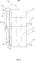
- liquid sanitizer With reference to Figure 2 , the liquid sanitizer will be described in further detail.
- the liquid sanitizer 200 has a tank 202, a heater 210 and a processor 230.
- the tank 202 contains, in use, a volume of water 203.
- the tank 202 has an inlet 204 and a drain 206.
- the inlet 204 is connectable to a water source (not shown) and the drain 206 is connectable to a waste pipe (also not shown).
- the tank 202 also has a feed pipe 220 connectable to the dummy cartridge 16 via the platen 21 and a return pipe 224, also connectable to the dummy cartridge 16 via the platen 21.
- the dummy cartridge 16 has a sanitizing water circulation path 17 so as to complete a sanitizing water circuit comprising the tank 202, feed pipe 220, dummy cartridge 16 and return pipe 224.
- the heater 210 has a heating element 212 arranged to heat the volume of water 203 contained within the tank 202, in this case by immersion in the volume of water 203 in the tank 202.
- the heater 210 is electronically connected to processor 230 by heater connector 211.
- Temperature sensors are arranged on the sanitizing water circuit.
- a driver temperature sensor 222 is arranged on the feed pipe 220 adjacent the water tank 202.
- a return temperature sensor 226 is arranged on the return pipe 224 adjacent the water tank 202.
- a check temperature sensor 228 is arranged on the return pipe adjacent, but offset from, the return temperature sensor 226. All three temperature sensors are electronically connected to the processor 230 via sensor connectors.
- Driver temperature sensor 222 is electronically connected to processor 230 by sensor connector 223.
- Return temperature sensor 226 is electronically connected to processor 230 by sensor connector 227.
- Check temperature sensor 228 is electronically connected to processor 230 by sensor connector 229.
- the electronic connectors 211, 223, 228, 229 may be wired or wireless.
- the processor 203 may be remote to both the tank 202 and heater 210.
- the processor 230 thereby controls both the heating of the water and receives the temperature values for the sanitizing water circuit.
- the tank 202 of liquid sanitizer 200 is filled with the desired quantity of water via inlet 204. This would typically be 500ml, which is the amount sufficient to flush out the water circuit of a kidney dialyser.
- the liquid sanitizer is then turned on.
- the processor 230 activates the heater 210 to heat the volume of water via the heating element 221 and the pump draws the water around the sanitizing water circuit.
- the temperature of the water exiting the tank 202 via feed pipe 220 is periodically sensed by drive temperature sensor 222, and the temperature data is periodically sent to processor 230 via sensor connector 223.
- the temperature of the water returning to the tank 202 via return pipe 224 is periodically sensed by return temperature sensor 226, and the temperature data is periodically sent to processor 230 via sensor connector 227.
- the processor 230 therefore periodically receives sensed temperature data to provide a feedback loop to moderate the heating of the volume of water 203 to maintain the temperature of the volume of water 203 above a threshold temperature.
- the processor 230 When the processor 230 receives data from the sensor 220 that the volume of water 203 has exceeded the threshold temperature, the processor 230 periodically samples the temperature of the volume of water via the return temperature sensor 226, which theoretically represents the lowest possible temperature of the water on the sanitizing water circuit.
- the value is checked by periodically sampling the temperature of the volume of water via the check temperature sensor 228.
- the sampling is performed periodically at, for example, 1 second intervals.
- the sampling intervals may be varied as appropriate.
- Each sampled temperature represents a time-temperature value, which can be calculated by the processor 230.
- the time-temperature value can be generated by a look-up table.
- the processor 230 calculates a cumulative time-temperature value for the volume of liquid 20 by summing the sampled time-temperature values. This is compared to a target total time-temperature value indicative of a sanitizing dose.
- the processor 230 sends an output signal to indicate that a sanitizing dose has been reached.
- the output signal is received by the heater and automatically switches off the heater 210.
- the processor 230 may switch off the water heater 210 in advance of a sanitizing dose being reached, by calculating that there is sufficient thermal energy contained within the water circuit that the water temperature will remain above the threshold temperature for long enough to ensure a sanitizing dose is reached. In that case, periodic sampling would be continued, such that the processor 230 is able to send the output signal to indicate that a sanitizing dose had indeed been reached.
- the output signal is received by the LCD display unit, which displays the text "COMPLETE" in reference to the completed sanitizing dose.
- the LCD display unit includes an audible alarm.
- the audible alarm can be configured to bleep repeatedly until the sanitizer is turned off.
- a typical temperature profile 300 of the water in a known liquid sanitizer is shown during a single disinfection cycle.
- the water already contained within the tank is at room temperature 301 (18°C) initially. As cool fresh water is added from a tap to ensure the correct quantity of water is provided in the tank (wherein the cool fresh water is typically 8°C), the overall temperature of the liquid will drop slightly 302.
- the water temperature then rises substantially linearly towards the target temperature of 80°C 305, which is reached at about 60 seconds.
- the water heater is switched off 307 and the water temperature steadily decreases to room temperature (18°C) 301.
- a typical temperature profile 400 of the water in the liquid sanitizer 200 is shown during a single disinfection cycle.
- the initial drop in temperature 402 from room temperature 401 (18°C) and subsequent heating of the water occurs following a similar time-temperature profile to that shown in Figure 3 .
- the liquid sanitizer begins to record a time-temperature value.
- the water temperature is continually raised 406 such that a greater time-temperature value contribution can be achieved with each sample.
- the heater is switched off 407 after less than 8 minutes as there is sufficient thermal energy within the water to ensure that a complete sanitizing dose is achieved before the temperature of the water falls below the threshold temperature of 65°C 403.
- the overall cycle time for the sanitizing dose is slightly more than 8 minutes. This compares to the overall cycle time for a sanitizing dose according to the temperature profile of Figure3 of over 30 minutes.
- An exemplary Lookup Table may include the following values for 1 second sampled increments: Table 1: Lookup Table Temperature (°C) Time-temperature value 95 35.481 94 28.184 93 22.387 92 17.783 91 14.125 90 11.22 89 8.913 88 7.079 87 5.623 86 4.467 85 3.548 84 2.818 83 2.239 82 1.778 81 1.413 80 1.122 79 0.891 78 0.708 77 0.562 76 0.447 75 0.355 74 0.282 73 0.224 72 0.178 71 0.141 70 0.112 69 0.089 68 0.071 67 0.056 66 0.045 65 0.035 64 0
- FIG 5 the non-linear contribution to the cumulative time-temperature value, during the single disinfection cycle referred to in the typical temperature profile of Figure 4 , is shown in the main graph.
- the main graph has the cumulative time temperature value on the Y-axis, and the cycle time (in seconds) on the X-axis.
- Three distinct periods of 10, one second samples are represented in charts 510, 520, 530, during the disinfection cycle, representing different regions of the main graph.
- the charts 510, 520, 530 show the time-temperature value contribution for each second according to the temperature sensed during the 1 second intervals.
- chart 510 the 10, one second samples are taken after approximately 50 seconds. During the 10 seconds, the water temperature increases from 64 to 67°C. This is shown by the line graph corresponding to the water temperature Y-axis on the left hand side of the chart. The time temperature contribution at these temperatures is represented by the bars, corresponding to the time temperature Y-axis on the right hand side of the chart.
- chart 520 the 10, one second samples are taken after approximately 140 seconds. During the 10 seconds, the water temperature increases from 79 to 82°C. This is shown by the line graph corresponding to the water temperature Y-axis on the left hand side of the chart. The time temperature contribution at these temperatures is represented by the bars, corresponding to the time temperature Y-axis on the right hand side of the chart. Note the difference in scale of the time temperature Y-axis of chart 520 to chart 510.
- chart 530 the 10, one second samples are taken after approximately 420 seconds. During the 10 seconds, the water temperature increases from 83 to 86°C. This is shown by the line graph corresponding to the water temperature Y-axis on the left hand side of the chart. The time temperature contribution at these temperatures is represented by the bars, corresponding to the time temperature Y-axis on the right hand side of the chart. Note the difference in scale of the time temperature Y-axis of chart 530 to charts 510 and 520.
- sampling interval could be longer or shorter.
- a longer sampling interval would preferably be associated with a steady temperature profile, whilst a shorter temperature cycle would preferably be associated with greater processing power.
- the processor may be programmable. Therefore the threshold temperature may be set manually. For example the threshold temperature may be set to a temperature between 55°C and 65°C.
- the overall heating time may be set manually. For example, the heating time may be set to 8, 9 or 10 minutes.
- the processor 230 calculates the necessary temperature profile over the heating time to ensure the volume of water receives a sanitizing dose.
Landscapes
- Health & Medical Sciences (AREA)
- Heart & Thoracic Surgery (AREA)
- Life Sciences & Earth Sciences (AREA)
- Urology & Nephrology (AREA)
- Engineering & Computer Science (AREA)
- General Health & Medical Sciences (AREA)
- Animal Behavior & Ethology (AREA)
- Veterinary Medicine (AREA)
- Public Health (AREA)
- Biomedical Technology (AREA)
- Emergency Medicine (AREA)
- Vascular Medicine (AREA)
- Anesthesiology (AREA)
- Hematology (AREA)
- Water Supply & Treatment (AREA)
- Chemical & Material Sciences (AREA)
- Environmental & Geological Engineering (AREA)
- Hydrology & Water Resources (AREA)
- Organic Chemistry (AREA)
- Epidemiology (AREA)
- External Artificial Organs (AREA)
- Apparatus For Disinfection Or Sterilisation (AREA)
Description
- The present invention relates to the preparation of dialysis fluid for hemodialysis and related therapies and substitution fluid for use in online therapies, such as hemodiafiltration and hemofiltration. In particular, the present invention relates to a method for heat sanitization of a liquid used in one of the above processes.
-
WO 00/57935 WO 96/25214 US 2004/215129 discloses a method and cycler for the administration of peritoneal dialysis fluid,WO 2014/082855 discloses systems, apparatus, equipment for thermal disinfection and thermal disinfection methods, andDE 2934167 discloses heat sterilization process control. - It is known to use heat to destroy microorganisms. During a thermal destruction process, the rate of destruction of microorganisms is logarithmic, as is the rate of growth of the microorganisms. Thus bacteria subjected to heat are killed at a rate that is proportional to the number of organisms present. The process is dependent both on the temperature of exposure and the time required at this temperature to accomplish to desired rate of destruction.
- Thermal calculations thus involve the need for knowledge of the concentration of organisms to be destroyed, the acceptable concentration of organisms that can remain behind (spoilage organisms, for example, but not pathogens), the thermal resistance of the target organisms (the most heat tolerant ones), and the time-temperature relationship required for destruction of the target organisms.
- Disinfection of many water based systems in medical devices is frequently achieved by elevating the temperature for a stipulated period of time, thereby using heat to destroy the microorganism in the water. In dialysis it is common for a combination of 80 degrees Celsius (°C) to be maintained for 30 minutes.
WO 00/57935 WO 96/25214 - There are several well-established time-temperature relationships for moist heat disinfection which are regarded as equally acceptable. For moist heat disinfection a particular time at a particular temperature can be expected to have a predictable lethal effect against a standardised population of organisms. It is therefore possible to define a standard exposure which will yield a disinfected product in a correctly operated Washer Disinfector (WD). Actual exposures can then be related to these standard exposure conditions.
- Definition of such disinfection processes may be achieved by means of the A0 method which uses a knowledge of the lethality of the particular process at different temperatures to assess the overall lethality of the cycle and express this as the equivalent exposure time at a specified temperature.
- The A value is a measure of the heat resistance of a microorganism.
- A is defined as the equivalent time in seconds at 80°C to give a disinfection effect.
- The z value indicates the temperature sensitivity of the reaction. It is defined as the change in temperature required to change the A value by a factor of 10.
- When the z value is 10°C, the term Ao is used.
- The Ao value of moist heat disinfection process is the equivalent time in seconds at a temperature of 80°C delivered by that process to the product with reference to microorganisms possessing a z value of 10°C.

- A0 is the A value when z is 10°C;
- t is the chosen time interval, in seconds;
- and T is the temperature in the load in °C.
- In calculating Ao values a temperature threshold for the integration is set at 65°C since for temperatures below 65°C the z and D value of thermophillic organisms may change dramatically and below 55°C there are a number or organisms which will actively replicate.
- In dialysis current practice, raising the temperature to 80°C for 30 minutes gives a benchmark value A0 equal to 1800.
- The present invention aims to provide an efficient method of heat sanitization of a haemodialysis water circuit.
- According to the first aspect of the present invention, there is provided a method of heat sanitization of a haemodialysis water circuit according to
claim 1. - Calculation of the time-temperature value for the volume of liquid based on the cumulative effect of heating the water provides a more accurate model of the sanitization process by ensuring a fixed dose of heat sanitization is applied to the volume of liquid. Furthermore, it maximises the benefits of high temperatures (in particular those above 80°C) thereby reducing the time for which components are exposed to elevated temperatures. Natural variation in the control loop and water recirculation will cause natural temperature oscillations. Those time periods below 80°C but above the minimum temperature range are integrated into the dose and those above are not leveraged according to the power law relationship.
- The method may comprise the further step of setting a target cumulative time-temperature value and providing the output signal once the target cumulative time-temperature value is reached.
- The output signal may be in the form of an audible or visual alarm. This informs the user or operator that the sanitization process is complete.
- The output signal may automatically cause termination of the liquid heating. This prevents the heat sanitization cycle from running for longer than is necessary.
- The method may comprises the further step of maintaining the volume of liquid below an upper temperature. This may be to prevent boiling of the sanitizing liquid, or prevent unnecessary thermal stress on the components of the heat sanitization device.
- The method may comprise the further step of setting the threshold temperature. The method may comprise the further step of setting an overall heating time. This allows the process to be tailored according to the environmental conditions (for example room temperature, liquid input temperature) the situational conditions, (for example emergency procedure, routine procedure, clinic timetables) and the patient's needs. Thus the time and/or temperature may be selected without compromising the dose of heat sanitization applied to the volume of liquid.
- The threshold temperature may be between 55°C and 65°C.
- The upper temperature may be between 70°C and 99°C.
- Multiple temperature sensors may be used to provide the temperature of the volume of liquid.
- In one embodiment, the cumulative time-temperature value may be calculated according to

- A0 is the A value when z is 10°C;
- t is the chosen time interval, in seconds;
- and T is the temperature in the load in °C.
- This allows the destruction of organisms at 65°C to 80°C to be included in the calculation of the cumulative time-temperature value.
- The A0 value may be equal to 1800.
- According to a second aspect of the present invention, there is provided a medical device defining a haemodialysis water circuit according to claim 11.
- The processor may be programmable to alter at least one of the threshold temperature and the cumulative time-temperature value.
- According to a third aspect of the present invention, there is provided a dialyser incorporating the medical device according to the second aspect of the present invention.
- An embodiment of the present invention will now be described, by way of example only, with reference to the accompanying figures, in which:
-
Figure 1 is a schematic of a dialysis machine incorporating the liquid sanitizer; -
Figure 2 is a magnified detail view of the liquid sanitizer ofFigure 1 ; -
Figure 3 is a temperature profile of the liquid in a liquid sanitizer undergoing a typical sanitization cycle; and -
Figure 4 is a temperature profile of the liquid in the liquid sanitizer ofFigure 1 undergoing a typical sanitization cycle. - Referring to
Figure 1 , adialysis machine 10 is shown having amain body 12 and a hingeddoor 14. Thedoor 14 is hinged so as to allow adummy dialysis cartridge 16 to be received between themain body 12 and the door. - The
machine 10 has a blood pumping portion indicated generally at 9 for pumping patient blood to and from a dialyser (not shown for clarity) in a known manner. Themain body 12 has aplaten 21 behind which is an engine portion (not shown for clarity). Theplaten 21 is configured to receive thedummy cartridge 16 within a recessedportion 25. - The engine portion includes a pneumatic pump for providing pressure and vacuum to operate the machine and a controller to control retention of the
dummy cartridge 16 within themachine 10 and fluid flow on thedummy cartridge 16 as will be discussed in further detail below. - The
door 14 has an outer side including auser interface 2. Thedoor 14 includes an actuator in the form of an airbag (not shown), operable by the engine portion to provide a closure load to close thedummy cartridge 16 onto theplaten 21 and to ensure that a continuous seal fully engages thedummy cartridge 16. - The
dummy cartridge 16 will now be described in further detail. Thedummy cartridge 16 has a chassis defining a door side and a platen side. In use the platen side of thecartridge 16 engages theplaten 21 on themain body 12 of themachine 10, and the door side engages an interface plate (not shown) on thedoor 14 of themachine 10. - The
dummy cartridge 16 is formed from an acrylic such as SG-10 which is moulded in two parts (a platen side and a patient side) before being bonded together to form the chassis. Both the platen side and door side are covered in a clear flexible membrane formed from, for example, DEHP-free PVC which is operable by pneumatic pressure applied to the membrane by the pneumatic compressor in the main body via theplaten 21. In this way a series offlow paths 17 are formed in the cartridge for carrying sanitizing water. - In use, the engine portion of the
machine 10 applies either a positive or negative pressure to the membrane via theplaten 21 in order to selectively open and close valves and pumps to pump sanitizing fluid through thedummy cartridge 16, which is described in detail below. - The
machine 10 has liquid sanitizer generally designated as 200. The arrows onFigure 1 show the sanitizing water flow path when the liquid sanitizer is in use. - With reference to
Figure 2 , the liquid sanitizer will be described in further detail. - The liquid sanitizer 200 has a
tank 202, aheater 210 and aprocessor 230. Thetank 202 contains, in use, a volume ofwater 203. - The
tank 202 has aninlet 204 and adrain 206. Theinlet 204 is connectable to a water source (not shown) and thedrain 206 is connectable to a waste pipe (also not shown). Thetank 202 also has afeed pipe 220 connectable to thedummy cartridge 16 via theplaten 21 and areturn pipe 224, also connectable to thedummy cartridge 16 via theplaten 21. Referring back toFigure 1 , thedummy cartridge 16 has a sanitizingwater circulation path 17 so as to complete a sanitizing water circuit comprising thetank 202,feed pipe 220,dummy cartridge 16 andreturn pipe 224. - The
heater 210 has aheating element 212 arranged to heat the volume ofwater 203 contained within thetank 202, in this case by immersion in the volume ofwater 203 in thetank 202. Theheater 210 is electronically connected toprocessor 230 byheater connector 211. - Temperature sensors are arranged on the sanitizing water circuit. A
driver temperature sensor 222 is arranged on thefeed pipe 220 adjacent thewater tank 202. Areturn temperature sensor 226 is arranged on thereturn pipe 224 adjacent thewater tank 202. Acheck temperature sensor 228 is arranged on the return pipe adjacent, but offset from, thereturn temperature sensor 226. All three temperature sensors are electronically connected to theprocessor 230 via sensor connectors.Driver temperature sensor 222 is electronically connected toprocessor 230 bysensor connector 223.Return temperature sensor 226 is electronically connected toprocessor 230 bysensor connector 227.Check temperature sensor 228 is electronically connected toprocessor 230 bysensor connector 229. - The
electronic connectors processor 203 may be remote to both thetank 202 andheater 210. - The
processor 230 thereby controls both the heating of the water and receives the temperature values for the sanitizing water circuit. - In use, the
tank 202 ofliquid sanitizer 200 is filled with the desired quantity of water viainlet 204. This would typically be 500ml, which is the amount sufficient to flush out the water circuit of a kidney dialyser. - The liquid sanitizer is then turned on. The
processor 230 activates theheater 210 to heat the volume of water via the heating element 221 and the pump draws the water around the sanitizing water circuit. The temperature of the water exiting thetank 202 viafeed pipe 220 is periodically sensed bydrive temperature sensor 222, and the temperature data is periodically sent toprocessor 230 viasensor connector 223. The temperature of the water returning to thetank 202 viareturn pipe 224 is periodically sensed byreturn temperature sensor 226, and the temperature data is periodically sent toprocessor 230 viasensor connector 227. Theprocessor 230 therefore periodically receives sensed temperature data to provide a feedback loop to moderate the heating of the volume ofwater 203 to maintain the temperature of the volume ofwater 203 above a threshold temperature. - When the
processor 230 receives data from thesensor 220 that the volume ofwater 203 has exceeded the threshold temperature, theprocessor 230 periodically samples the temperature of the volume of water via thereturn temperature sensor 226, which theoretically represents the lowest possible temperature of the water on the sanitizing water circuit. - The value is checked by periodically sampling the temperature of the volume of water via the
check temperature sensor 228. - The sampling is performed periodically at, for example, 1 second intervals. The sampling intervals may be varied as appropriate.
- Each sampled temperature represents a time-temperature value, which can be calculated by the
processor 230. In an alternate example not of the present invention, the time-temperature value can be generated by a look-up table. - The
processor 230 calculates a cumulative time-temperature value for the volume ofliquid 20 by summing the sampled time-temperature values. This is compared to a target total time-temperature value indicative of a sanitizing dose. - Once the calculated cumulative time-temperature value and the target cumulative time-temperature value are equal, the
processor 230 sends an output signal to indicate that a sanitizing dose has been reached. The output signal is received by the heater and automatically switches off theheater 210. - In an alternate embodiment, the
processor 230 may switch off thewater heater 210 in advance of a sanitizing dose being reached, by calculating that there is sufficient thermal energy contained within the water circuit that the water temperature will remain above the threshold temperature for long enough to ensure a sanitizing dose is reached. In that case, periodic sampling would be continued, such that theprocessor 230 is able to send the output signal to indicate that a sanitizing dose had indeed been reached. - The output signal is received by the LCD display unit, which displays the text "COMPLETE" in reference to the completed sanitizing dose. In alternate embodiments, the LCD display unit includes an audible alarm. The audible alarm can be configured to bleep repeatedly until the sanitizer is turned off.
- With reference to
Figure 3 , atypical temperature profile 300 of the water in a known liquid sanitizer is shown during a single disinfection cycle. - The water already contained within the tank is at room temperature 301 (18°C) initially. As cool fresh water is added from a tap to ensure the correct quantity of water is provided in the tank (wherein the cool fresh water is typically 8°C), the overall temperature of the liquid will drop slightly 302.
- The water temperature then rises substantially linearly towards the target temperature of 80°
C 305, which is reached at about 60 seconds. There is aslight oscillation 304 of about one and a half wavelengths where the water temperature exceeds and passes below 80°C (to approximately 85°C and 75°C respectively) as the water heater finds the correct balance to maintain a constant water temperature of 80°C. After approximately 30 minutes at 80°C the water heater is switched off 307 and the water temperature steadily decreases to room temperature (18°C) 301. - With reference to
Figure 4 atypical temperature profile 400 of the water in theliquid sanitizer 200 is shown during a single disinfection cycle. - Similar notable points on the temperature profile are given similar reference numerals as that for
Figure 3 , prefixed by a "4" instead of a "3" to indicate that they represent thetemperature profile 400 of the water in theliquid sanitizer 200. - The initial drop in
temperature 402 from room temperature 401 (18°C) and subsequent heating of the water occurs following a similar time-temperature profile to that shown inFigure 3 . - However, when the temperature of the water exceeds the threshold temperature. 65°
C 403, the liquid sanitizer begins to record a time-temperature value. - Furthermore, when the
target temperature 80°C 405 is reached, the water temperature is continually raised 406 such that a greater time-temperature value contribution can be achieved with each sample. - The heater is switched off 407 after less than 8 minutes as there is sufficient thermal energy within the water to ensure that a complete sanitizing dose is achieved before the temperature of the water falls below the threshold temperature of 65°
C 403. - The overall cycle time for the sanitizing dose is slightly more than 8 minutes. This compares to the overall cycle time for a sanitizing dose according to the temperature profile of
Figure3 of over 30 minutes. - An exemplary Lookup Table may include the following values for 1 second sampled increments:
Table 1: Lookup Table Temperature (°C) Time-temperature value 95 35.481 94 28.184 93 22.387 92 17.783 91 14.125 90 11.22 89 8.913 88 7.079 87 5.623 86 4.467 85 3.548 84 2.818 83 2.239 82 1.778 81 1.413 80 1.122 79 0.891 78 0.708 77 0.562 76 0.447 75 0.355 74 0.282 73 0.224 72 0.178 71 0.141 70 0.112 69 0.089 68 0.071 67 0.056 66 0.045 65 0.035 64 0 - Thus it can be seen that for each 1°C increase in water temperatures above 80°C, the time-temperature contribution is significantly increased. Three seconds at 85°C is equivalent to over 10 seconds at 80°C.
- In
Figure 5 , the non-linear contribution to the cumulative time-temperature value, during the single disinfection cycle referred to in the typical temperature profile ofFigure 4 , is shown in the main graph. The main graph has the cumulative time temperature value on the Y-axis, and the cycle time (in seconds) on the X-axis. Three distinct periods of 10, one second samples are represented incharts 510, 520, 530, during the disinfection cycle, representing different regions of the main graph. Thecharts 510, 520, 530 show the time-temperature value contribution for each second according to the temperature sensed during the 1 second intervals. - In chart 510, the 10, one second samples are taken after approximately 50 seconds. During the 10 seconds, the water temperature increases from 64 to 67°C. This is shown by the line graph corresponding to the water temperature Y-axis on the left hand side of the chart. The time temperature contribution at these temperatures is represented by the bars, corresponding to the time temperature Y-axis on the right hand side of the chart.
- No contribution is made when the water temperature is 64°C. A relatively small contribution to the time temperature value is made when the water temperature is 65 to 67°C. This corresponds to the flat region of the main graph. Summing the values for the bars indicates that the total contribution of the 10, one second intervals is 0.296. Although these contributions are small, they are counted and do contribute to shorten the time required for sanitisation. In the prior art, no credit is given for this heating phase.
- In
chart 520, the 10, one second samples are taken after approximately 140 seconds. During the 10 seconds, the water temperature increases from 79 to 82°C. This is shown by the line graph corresponding to the water temperature Y-axis on the left hand side of the chart. The time temperature contribution at these temperatures is represented by the bars, corresponding to the time temperature Y-axis on the right hand side of the chart. Note the difference in scale of the time temperature Y-axis ofchart 520 to chart 510. - Increasing contributions to the time temperature value are made as the water temperature increases from 79 to 82°C. This corresponds to the steadily increasing region of the main graph. Summing the values for the bars indicates that the total contribution of the 10, one second intervals is 12.056.
- In chart 530, the 10, one second samples are taken after approximately 420 seconds. During the 10 seconds, the water temperature increases from 83 to 86°C. This is shown by the line graph corresponding to the water temperature Y-axis on the left hand side of the chart. The time temperature contribution at these temperatures is represented by the bars, corresponding to the time temperature Y-axis on the right hand side of the chart. Note the difference in scale of the time temperature Y-axis of chart 530 to
charts 510 and 520. - Greatly increasing contributions to the time temperature value are made as the water temperature increases from 83 to 86°C. This corresponds to the steep region of the main graph. Summing the values for the bars indicates that the total contribution of the 10, one second intervals is 30.282. Counting the actual contribution to sanitisation for the periods above 80°C rather than treating these as the same as 80°C considerably shortens the required time.
- The charts are exemplary in nature only, and different time, temperature and associated time-temperature values are possible, and indeed envisaged.
- One second intervals have been chosen as a reasonable sampling rate. The sampling interval could be longer or shorter. A longer sampling interval would preferably be associated with a steady temperature profile, whilst a shorter temperature cycle would preferably be associated with greater processing power.
- In alternate embodiments of the liquid sanitizer, the processor may be programmable. Therefore the threshold temperature may be set manually. For example the threshold temperature may be set to a temperature between 55°C and 65°C. The overall heating time may be set manually. For example, the heating time may be set to 8, 9 or 10 minutes. In this case the
processor 230 calculates the necessary temperature profile over the heating time to ensure the volume of water receives a sanitizing dose.
Claims (15)
- A method of heat sanitization of a haemodialysis water circuit, the method comprising the steps of:providing a medical device;the medical device defining the haemodialysis water circuit, including:a tank (202) containing a volume of liquid;a sensor arranged to sense the temperature of the volume of liquid;a heater (210) arranged to heat the volume of liquid from an initial temperature to exceed a threshold temperature, and maintain the volume of liquid above the threshold temperature; anda processor (230), wherein the processor (230) is configured to perform the following steps:sensing the temperature of the volume of liquid with the sensor;heating the volume of liquid from an initial temperature to exceed a threshold temperature;maintaining the volume of liquid above the threshold temperature;determining a time-temperature value for the volume of liquid periodically once the threshold temperature has been exceeded;calculating a cumulative time-temperature value; and characterized by the processor (230) calculating whether there is sufficient thermal energy contained within the water circuit that the temperature of the volume of liquid will remain above the threshold temperature for long enough to ensure a sanitizing dose is reached; and the processor (230) switching off the heater in advance of a sanitizing dose being reached once there is sufficient thermal energy contained within the water circuit to ensure a sanitizing dose is reached;providing an output signal once the cumulative time-temperature value has reached a level indicative of a sanitizing dose.
- The method according to claim 1 further comprising the step of setting a target cumulative time-temperature value and providing the output signal once the target cumulative time-temperature value is reached.
- The method according to any preceding claim wherein the output signal is in the form of an audible or visual alarm.
- The method according to claim 2 or claim 3 wherein the output signal automatically causes termination of the liquid heating.
- The method according to any preceding claim comprising the step of maintaining the volume of liquid below an upper temperature, preferably comprising the further step of setting the upper temperature, preferably still wherein the upper temperature is between 70°C and 99°C.
- The method according to any preceding claim comprising the further step of setting the threshold temperature, preferably wherein the threshold temperature is between 55°C and 65°C.
- The method according to any preceding claim comprising the further step of setting an overall heating time.
- The method according to any preceding claim wherein multiple temperature sensors provide the temperature of the volume of liquid.
- The method according to any preceding claim wherein the cumulative time-temperature value is calculated according to
 A0 is the A value when z is 10°C;t is the chosen time interval, in seconds;and T is the temperature in the load in °C.
 - The method according to claim 9 where the Ao value is equal to 1800.
- A medical device defining a haemodialysis water circuit, including:a tank (202) containing a volume of liquid;a sensor arranged to sense the temperature of the volume of liquid;a heater (210) arranged to heat the volume of liquid from an initial temperature to exceed a threshold temperature, and maintain the volume of liquid above the threshold temperature; anda processor (230), wherein the processor (230) is configured to determine a time-temperature value for the volume of liquid periodically once the threshold temperature has been exceeded and calculate a cumulative time-temperature value so as to provide an output signal once a cumulative time-temperature value indicative of a sanitizing dose is reached, and characterized in that the processor (230 is further configured to calculate whether there is sufficient thermal energy contained within the water circuit that the temperature of the volume of liquid will remain above the threshold temperature for long enough to ensure a sanitizing dose is reached and to switch off the heater in advance of a sanitizing dose being reached once there is sufficient thermal energy contained within the water circuit to ensure a sanitizing dose is reached.
- The medical device defining a haemodialysis water circuit of claim 11 wherein the device comprises at least one of a cartridge (16), a door (14), a pneumatic pump, preferably wherein the medical device is a kidney dialyser.
- The medical device of claim 12 wherein the processor (230) is programmable to alter at least one of the threshold temperature and the cumulative time-temperature value, preferably wherein the processor performs the steps of any of claims 2, 5 to 7.
- The medical device of claim 11 or claim 12 wherein the processor determines the cumulative time-temperature value according to:
 A0 is the A value when z is 10°C;t is the chosen time interval, in seconds;and T is the temperature in the load in °C preferably wherein the A0 value is 1800.
 - A kidney dialyser incorporating the medical device of any of claims 12 to 14.
Priority Applications (1)
| Application Number | Priority Date | Filing Date | Title |
|---|---|---|---|
| EP19216141.2A EP3646904B1 (en) | 2014-06-02 | 2015-06-02 | Method of heat sanitization of a haemodialysis water circuit using a calculated dose |
Applications Claiming Priority (2)
| Application Number | Priority Date | Filing Date | Title |
|---|---|---|---|
| GBGB1409796.8A GB201409796D0 (en) | 2014-06-02 | 2014-06-02 | Method of heat sanitization of a haemodialysis water circuit using a calculated dose |
| PCT/GB2015/051610 WO2015185920A1 (en) | 2014-06-02 | 2015-06-02 | Method of heat sanitization of a haemodialysis water circuit using a calculated dose |
Related Child Applications (1)
| Application Number | Title | Priority Date | Filing Date |
|---|---|---|---|
| EP19216141.2A Division EP3646904B1 (en) | 2014-06-02 | 2015-06-02 | Method of heat sanitization of a haemodialysis water circuit using a calculated dose |
Publications (2)
| Publication Number | Publication Date |
|---|---|
| EP3148605A1 EP3148605A1 (en) | 2017-04-05 |
| EP3148605B1 true EP3148605B1 (en) | 2019-12-18 |
Family
ID=51214609
Family Applications (2)
| Application Number | Title | Priority Date | Filing Date |
|---|---|---|---|
| EP19216141.2A Active EP3646904B1 (en) | 2014-06-02 | 2015-06-02 | Method of heat sanitization of a haemodialysis water circuit using a calculated dose |
| EP15728094.2A Active EP3148605B1 (en) | 2014-06-02 | 2015-06-02 | Method of heat sanitization of a haemodialysis water circuit using a calculated dose |
Family Applications Before (1)
| Application Number | Title | Priority Date | Filing Date |
|---|---|---|---|
| EP19216141.2A Active EP3646904B1 (en) | 2014-06-02 | 2015-06-02 | Method of heat sanitization of a haemodialysis water circuit using a calculated dose |
Country Status (5)
| Country | Link |
|---|---|
| US (4) | US10543305B2 (en) |
| EP (2) | EP3646904B1 (en) |
| ES (1) | ES2777300T3 (en) |
| GB (1) | GB201409796D0 (en) |
| WO (1) | WO2015185920A1 (en) |
Families Citing this family (21)
| Publication number | Priority date | Publication date | Assignee | Title |
|---|---|---|---|---|
| GB201305755D0 (en) | 2013-03-28 | 2013-05-15 | Quanta Fluid Solutions Ltd | Re-Use of a Hemodialysis Cartridge |
| GB201314512D0 (en) | 2013-08-14 | 2013-09-25 | Quanta Fluid Solutions Ltd | Dual Haemodialysis and Haemodiafiltration blood treatment device |
| JP6657186B2 (en) | 2014-04-29 | 2020-03-04 | アウトセット・メディカル・インコーポレイテッドOutset Medical, Inc. | Dialysis system and method |
| GB201409796D0 (en) * | 2014-06-02 | 2014-07-16 | Quanta Fluid Solutions Ltd | Method of heat sanitization of a haemodialysis water circuit using a calculated dose |
| GB201523104D0 (en) | 2015-12-30 | 2016-02-10 | Quanta Fluid Solutions Ltd | Dialysis machine |
| GB2547214A (en) | 2016-02-10 | 2017-08-16 | Quanta Fluid Solutions Ltd | Membrane pump usage condition detection |
| US11534537B2 (en) | 2016-08-19 | 2022-12-27 | Outset Medical, Inc. | Peritoneal dialysis system and methods |
| DE102016117600A1 (en) * | 2016-09-19 | 2018-03-22 | B. Braun Avitum Ag | Method for disinfecting a hydraulic system of a device for extracorporeal blood treatment by means of hot disinfection and such device |
| GB201622119D0 (en) | 2016-12-23 | 2017-02-08 | Quanta Dialysis Tech Ltd | Improved valve leak detection system |
| GB201701740D0 (en) | 2017-02-02 | 2017-03-22 | Quanta Dialysis Tech Ltd | Phased convective operation |
| GB201703048D0 (en) | 2017-02-24 | 2017-04-12 | Quanta Dialysis Tech Ltd | Testing rotor engagement of a rotary peristaltic pump |
| GB201705273D0 (en) | 2017-03-31 | 2017-05-17 | Quanta Dialysis Tech Ltd | Data storage amd exchange by medical device components |
| GB201710546D0 (en) | 2017-06-30 | 2017-08-16 | Quanta Dialysis Tech Ltd | Dialysis systems, devices and methods |
| USD907211S1 (en) | 2017-09-28 | 2021-01-05 | Quanta Dialysis Technologies Ltd. | Dialysis machine |
| ES3040537T3 (en) * | 2017-10-17 | 2025-11-03 | Evoqua Water Tech Llc | Reverse osmosis water system with heat forward function |
| AU2019325668B2 (en) | 2018-08-23 | 2025-03-27 | Outset Medical, Inc. | Dialysis system and methods |
| GB201903247D0 (en) * | 2019-03-11 | 2019-04-24 | Nicoventures Trading Ltd | Aerosol provision device |
| AU2020266584B2 (en) | 2019-04-30 | 2025-10-23 | Outset Medical, Inc. | Dialysis system and methods |
| GB2584335A (en) | 2019-05-31 | 2020-12-02 | Quanta Dialysis Technologies Ltd | Source container connector |
| GB2596811A (en) | 2020-07-06 | 2022-01-12 | Quanta Dialysis Technologies Ltd | Dialysis system |
| DE102023119706A1 (en) * | 2023-07-25 | 2025-01-30 | B.Braun Avitum Ag | Method for disinfecting a fluid line system of a medical device and medical device |
Citations (1)
| Publication number | Priority date | Publication date | Assignee | Title |
|---|---|---|---|---|
| US20100263687A1 (en) * | 2009-04-16 | 2010-10-21 | Markus Braun | Cleaning method with improved long-term hygiene effect |
Family Cites Families (254)
| Publication number | Priority date | Publication date | Assignee | Title |
|---|---|---|---|---|
| CA81430S (en) | 1997-08-15 | Aksys Ltd | Dialysis machine | |
| US2696173A (en) | 1950-12-23 | 1954-12-07 | Jensen Thormod | Fluid pump |
| US3338171A (en) | 1965-09-15 | 1967-08-29 | Du Pont | Pneumatically operable diaphragm pumps |
| US3468261A (en) | 1967-01-23 | 1969-09-23 | Altec Ges Fur Allg Landtechnik | Pump |
| FR1552305A (en) | 1967-12-15 | 1969-01-03 | ||
| US3606592A (en) | 1970-05-20 | 1971-09-20 | Bendix Corp | Fluid pump |
| US4370983A (en) | 1971-01-20 | 1983-02-01 | Lichtenstein Eric Stefan | Computer-control medical care system |
| US3774762A (en) | 1971-01-20 | 1973-11-27 | E Lichtenstein | Analogue fluid flow programming structures |
| DE2116456A1 (en) | 1971-04-03 | 1972-10-12 | Pumpenfabrik Urach, 7417 Urach | Diaphragm pump for conveying liquid or gaseous media |
| US3753493A (en) | 1971-04-23 | 1973-08-21 | E Mellor | Artificial kidney cleaning apparatus |
| GB1418181A (en) | 1973-02-27 | 1975-12-17 | Cole E M | Ultrasonic detection of inclusions in a fluid flowing within a tube |
| US3972320A (en) | 1974-08-12 | 1976-08-03 | Gabor Ujhelyi Kalman | Patient monitoring system |
| FR2310136A1 (en) | 1975-05-07 | 1976-12-03 | Bernas Medical | Automatic cleaner for dialysers for artificial kidneys - incorporating programming of washing, rinsing and sterilising several dialysers simultaneously |
| US4070725A (en) | 1975-11-07 | 1978-01-31 | Cornelius Eng | Combined pump and siphon |
| US4142845A (en) | 1976-02-20 | 1979-03-06 | Lepp William A | Dialysis pump system having over-center cam tracks to lock rollers against tubing |
| US4161264A (en) | 1977-06-17 | 1979-07-17 | Johnson Bryan E | Fluid metering and mixing device having inlet and outlet valves |
| US4205686A (en) | 1977-09-09 | 1980-06-03 | Picker Corporation | Ultrasonic transducer and examination method |
| DE2934167A1 (en) | 1979-08-23 | 1981-03-26 | MMM Münchener Medizin Mechanik GmbH, 80639 München | Heat sterilisation process control - has integrator for measured core temp. time and stored cooling data providing output for comparison with reference |
| DE2950381A1 (en) | 1979-12-14 | 1981-06-19 | Boehringer Mannheim Gmbh, 6800 Mannheim | METHOD AND REAGENT FOR DETERMINING TRIGLYCERIDES |
| US4324662A (en) | 1979-12-28 | 1982-04-13 | Baxter Travenol Laboratories, Inc. | Flow reversal in a dialyzer |
| US4366061A (en) | 1980-01-23 | 1982-12-28 | Cordis Dow Corp. | Automated diaphragm apparatus and method for controlling negative pressure hemodialysis treatment |
| ATE10670T1 (en) | 1980-12-29 | 1984-12-15 | Lewa Herbert Ott Gmbh + Co. | DIAPHRAGM PUMP WITH RELIEVED CLAMPED DIAPHRAGM. |
| US4353990A (en) * | 1981-02-09 | 1982-10-12 | Minnesota Mining And Manufacturing Company | Sanitation indicator |
| US4534755A (en) | 1982-02-22 | 1985-08-13 | Hoccum Developments Limited | Centrifuges |
| DE3225323C2 (en) | 1982-07-07 | 1984-05-24 | Messerschmitt-Bölkow-Blohm GmbH, 8012 Ottobrunn | Connecting rod made of fiber-reinforced plastic |
| US4494912A (en) | 1982-09-16 | 1985-01-22 | Pauliukonis Richard S | Energy conserving air pump |
| US4534756A (en) | 1983-04-11 | 1985-08-13 | Ivac Corporation | Fault detection apparatus and method for parenteral infusion system |
| USD277991S (en) | 1983-05-12 | 1985-03-12 | Marketing International, Inc. | Cart for handling biological tissue |
| DE3326786A1 (en) | 1983-07-25 | 1985-02-14 | Fresenius AG, 6380 Bad Homburg | PUMP BED FOR A ROLL PUMP |
| FR2558063B1 (en) | 1984-01-18 | 1987-02-20 | Hospal Ind | ARTIFICIAL KIDNEY WITH SINGLE NEEDLE |
| CS248305B1 (en) | 1984-06-18 | 1987-02-12 | Miroslav Skala | Blood cleaning instrument |
| US5643201A (en) | 1984-07-09 | 1997-07-01 | Peabody; Alan M. | Continuous peritoneal dialysis apparatus |
| US4771792A (en) | 1985-02-19 | 1988-09-20 | Seale Joseph B | Non-invasive determination of mechanical characteristics in the body |
| US4666598A (en) | 1985-06-25 | 1987-05-19 | Cobe Laboratories, Inc. | Apparatus for use with fluid flow transfer device |
| US4648869A (en) | 1985-12-04 | 1987-03-10 | American Hospital Supply Corporation | Automatic infiltration detection system and method |
| US4828543A (en) | 1986-04-03 | 1989-05-09 | Weiss Paul I | Extracorporeal circulation apparatus |
| US4710163A (en) | 1986-06-06 | 1987-12-01 | Ivac Corporation | Detection of fluid flow faults in the parenteral administration of fluids |
| US4897184A (en) | 1986-10-31 | 1990-01-30 | Cobe Laboratories, Inc. | Fluid flow apparatus control and monitoring |
| USD308249S (en) | 1987-09-25 | 1990-05-29 | Delmed, Inc. | Peritoneal dialysis machine |
| US4979940A (en) | 1988-03-08 | 1990-12-25 | Baxter International Inc. | Infusion system, methodology, and algorithm for identifying patient-induced pressure artifacts |
| US5012197A (en) | 1988-04-19 | 1991-04-30 | Volkhard Seiffert | Apparatus and method for determining the relative percentages of components in a mixture |
| WO1990007648A1 (en) | 1988-12-29 | 1990-07-12 | Chang, Victor, Peter | Diaphragm pump |
| US5000664A (en) | 1989-06-07 | 1991-03-19 | Abbott Laboratories | Apparatus and method to test for valve leakage in a pump assembly |
| US5252213A (en) | 1989-06-20 | 1993-10-12 | University Of Washington | Dry dialysate composition |
| US4969991A (en) | 1989-08-30 | 1990-11-13 | Valadez Gerardo M | Water purifying and dispensing system |
| US5103211A (en) | 1989-11-02 | 1992-04-07 | Ivac Corporation | Apparatus for detecting fluid line occlusion |
| US5055198A (en) | 1990-03-07 | 1991-10-08 | Shettigar U Ramakrishna | Autologous blood recovery membrane system and method |
| JP2863597B2 (en) | 1990-03-30 | 1999-03-03 | 株式会社東芝 | Clamp circuit |
| NL9000867A (en) | 1990-04-12 | 1991-11-01 | Bredel Exploitatie Bv | HOSE PUMP WITH RETRACTABLE PRESS BODIES. |
| US5095910A (en) | 1990-04-18 | 1992-03-17 | Advanced Technology Laboratories, Inc. | Ultrasonic imaging of biopsy needle |
| US5032265A (en) | 1990-06-20 | 1991-07-16 | Millipore Corporation | Method and system for producing sterile aqueous solutions |
| US5232434A (en) | 1990-10-05 | 1993-08-03 | Aisin Seiki Kabushiki Kaisha | Fluid feeding pump unit |
| US5558347A (en) | 1990-12-31 | 1996-09-24 | Specialist Sealing Limited | Seal |
| JP3041837B2 (en) | 1991-02-20 | 2000-05-15 | 東洋紡績株式会社 | Blood flow measurement method and artificial heart drive system |
| US5665307A (en) * | 1991-03-27 | 1997-09-09 | Fresenius Ag | Aqueous disinfecting agent |
| USD344339S (en) | 1991-08-23 | 1994-02-15 | Terumo Kabushiki Kaisha | Automatic blood separator |
| USD341890S (en) | 1991-10-25 | 1993-11-30 | Electromedics, Inc. | Autotransfusion system housing |
| DE4138140C2 (en) | 1991-11-20 | 1993-12-23 | Fresenius Ag | Device for disinfecting hemodialysis machines with a powdered concentrate |
| USD347896S (en) | 1992-04-30 | 1994-06-14 | Intravascular Research Limited | Medical ultrasound image display unit |
| US5586873A (en) | 1992-06-18 | 1996-12-24 | Novak; Pavel | Tube pump with retractable rollers |
| US5476368A (en) | 1992-08-20 | 1995-12-19 | Ryder International Corporation | Sterile fluid pump diaphragm construction |
| WO1994005345A1 (en) | 1992-09-02 | 1994-03-17 | Valery Viktorovich Skobelev | Pump for biological liquids |
| USD351470S (en) | 1993-03-03 | 1994-10-11 | Baxter International Inc. | Peritoneal dialysis cycler |
| US5350357A (en) | 1993-03-03 | 1994-09-27 | Deka Products Limited Partnership | Peritoneal dialysis systems employing a liquid distribution and pumping cassette that emulates gravity flow |
| JPH06261872A (en) | 1993-03-11 | 1994-09-20 | Toyobo Co Ltd | Blood volume measuring method and apparatus |
| US5385540A (en) | 1993-05-26 | 1995-01-31 | Quest Medical, Inc. | Cardioplegia delivery system |
| AU5352594A (en) | 1993-08-23 | 1995-03-21 | W.L. Gore & Associates, Inc. | Pre-failure warning pump diaphragm |
| JP3199938B2 (en) | 1993-12-17 | 2001-08-20 | 日機装株式会社 | Leak detection device for shutoff mechanism in flow passage |
| GB9405523D0 (en) | 1994-03-21 | 1994-05-04 | Graseby Medical Ltd | Pumping and pressure detection using flexible tubes |
| US5476792A (en) * | 1994-04-05 | 1995-12-19 | Temple Division, Air Liquide America Corporation | Time-temperature indicator devices |
| SE510026C2 (en) * | 1994-09-23 | 1999-04-12 | Gambro Ab | Disinfection device for dialysis machine |
| USD370979S (en) | 1994-11-10 | 1996-06-18 | Pall Corporation | Fluid processing system |
| AUPN012194A0 (en) | 1994-12-16 | 1995-01-19 | University Of Queensland, The | Alumino-silicate derivatives |
| US6153102A (en) * | 1995-02-13 | 2000-11-28 | Aksys, Ltd. | Disinfection of dead-ended lines in medical instruments |
| US5788851A (en) | 1995-02-13 | 1998-08-04 | Aksys, Ltd. | User interface and method for control of medical instruments, such as dialysis machines |
| US5591344A (en) | 1995-02-13 | 1997-01-07 | Aksys, Ltd. | Hot water disinfection of dialysis machines, including the extracorporeal circuit thereof |
| US5650071A (en) | 1995-06-07 | 1997-07-22 | Cobe Laboratories, Inc. | Technique for priming and recirculating fluid through a dialysis machine to prepare the machine for use |
| WO1997003609A1 (en) | 1995-07-16 | 1997-02-06 | Ultra-Guide Ltd. | Free-hand aiming of a needle guide |
| US5772624A (en) | 1995-07-20 | 1998-06-30 | Medisystems Technology Corporation | Reusable blood lines |
| US5653456A (en) | 1995-07-21 | 1997-08-05 | Mough; Bryan M. | Ski system for ice fishing shanties |
| SE508374C2 (en) | 1995-09-12 | 1998-09-28 | Gambro Med Tech Ab | Method and apparatus for detecting the condition of a blood vessel access |
| US5759017A (en) | 1996-01-31 | 1998-06-02 | Medtronic Electromedics, Inc. | Peristaltic pump and tube loading system |
| US5727550A (en) | 1996-04-09 | 1998-03-17 | Lectec Corporation | Dual purpose ultrasonic biomedical couplant pad and electrode |
| JPH09330304A (en) | 1996-06-05 | 1997-12-22 | Internatl Business Mach Corp <Ibm> | How to determine the communication schedule between processors |
| SE510126C2 (en) | 1996-06-13 | 1999-04-19 | Althin Medical Ab | Dialysis machine with movable control panel |
| US5882300A (en) | 1996-11-07 | 1999-03-16 | Spacelabs Medical, Inc. | Wireless patient monitoring apparatus using inductive coupling |
| USD395085S (en) | 1997-04-25 | 1998-06-09 | Aksys, Ltd. | Dialysis machine |
| DE19734002C1 (en) | 1997-08-06 | 1998-09-17 | Fresenius Medical Care De Gmbh | Blood dialysis process with process monitoring system on dialysis machine |
| DE59814205D1 (en) | 1997-08-13 | 2008-05-21 | Fresenius Medical Care De Gmbh | A blood treatment device comprising a device for determining parameters of hemodialysis and methods for its determination |
| US5957670A (en) | 1997-08-26 | 1999-09-28 | Wilden Pump & Engineering Co. | Air driven diaphragm pump |
| US5995910A (en) | 1997-08-29 | 1999-11-30 | Reliance Electric Industrial Company | Method and system for synthesizing vibration data |
| CH692570A5 (en) | 1997-12-05 | 2002-08-15 | Peter F Meier | Apparatus for monitoring a catheter device. |
| GB9801138D0 (en) * | 1998-01-20 | 1998-03-18 | Eastman Kodak Co | Time temperature indicator devices |
| EP1119404B2 (en) | 1998-07-31 | 2013-05-01 | Nephros, Inc. | Device for efficient hemodiafiltration |
| US6331252B1 (en) | 1998-07-31 | 2001-12-18 | Baxter International Inc. | Methods for priming a blood compartment of a hemodialyzer |
| US6132378A (en) | 1998-08-10 | 2000-10-17 | Marino; Sharon | Cover for ultrasound probe |
| SE521219C2 (en) * | 1998-10-23 | 2003-10-14 | Gambro Ab | Method and apparatus for reducing the degradation of heat sensitive components in medical substances during heat sterilization |
| JP2000130334A (en) | 1998-10-26 | 2000-05-12 | Takuma Co Ltd | Diaphragm pump, diaphragm damage detection method, and ammonia absorption refrigerator including the same |
| DK173498B1 (en) | 1998-11-19 | 2001-01-08 | Coloplast As | An ostomy appliance |
| FR2790041B1 (en) | 1999-02-23 | 2002-01-18 | Fresenius Vial | METHOD FOR CONTROLLING A PUMPING DEVICE COMPRISING A PUMP PROVIDED WITH A FLEXIBLE TUBE AND DEVICE FOR IMPLEMENTING THE METHOD |
| SE9901165D0 (en) * | 1999-03-30 | 1999-03-30 | Gambro Lundia Ab | Method, apparatus and components of dialysis systems |
| SE9903331D0 (en) * | 1999-09-16 | 1999-09-16 | Gambro Lundia Ab | Method and apparatus for sterilizing a heat sensitive fluid |
| WO2000063658A2 (en) | 1999-04-15 | 2000-10-26 | Ultraguide Ltd. | Apparatus and method for detecting the bending of medical invasive tools in medical interventions |
| BR0009799B1 (en) | 1999-04-30 | 2009-01-13 | control and continuous hemoinfiltration systems. | |
| US6517239B1 (en) * | 1999-04-30 | 2003-02-11 | Ncr Corproation | Time-temperature indicators activated with thermal transfer printing and methods for their production |
| US6382923B1 (en) | 1999-07-20 | 2002-05-07 | Deka Products Ltd. Partnership | Pump chamber having at least one spacer for inhibiting the pumping of a gas |
| US6723062B1 (en) | 1999-09-03 | 2004-04-20 | Baxter International Inc. | Fluid pressure actuated blood pumping systems and methods with continuous inflow and pulsatile outflow conditions |
| US6261065B1 (en) | 1999-09-03 | 2001-07-17 | Baxter International Inc. | System and methods for control of pumps employing electrical field sensing |
| US20040215129A1 (en) * | 1999-09-16 | 2004-10-28 | Gambro Ab | Method and cycler for the administration of a peritoneal dialysis fluid |
| IT1308861B1 (en) | 1999-11-02 | 2002-01-11 | Gambro Dasco Spa | METHOD OF CONTROL OF A DIALYSIS EQUIPMENT DEDICATED TO THE IMPLEMENTATION OF THE AFBK DIALYTIC TECHNIQUE AND RELATED |
| US7347849B2 (en) | 2001-05-24 | 2008-03-25 | Nxstage Medical, Inc. | Modular medical treatment replaceable component |
| US6251279B1 (en) | 1999-12-09 | 2001-06-26 | Dialysis Systems, Inc. | Heat disinfection of a water supply |
| DE10012904B4 (en) | 2000-03-16 | 2004-08-12 | Lewa Herbert Ott Gmbh + Co | Membrane clamping with elasticity compensation |
| US6645176B1 (en) | 2000-04-28 | 2003-11-11 | Medtronic, Inc. | Spring loaded implantable drug infusion device |
| DE10024447A1 (en) | 2000-05-19 | 2001-11-29 | Asw Aqua System Wassertechnik | Process for producing ultrapure water and device for carrying out the process |
| US20030034305A1 (en) | 2001-01-05 | 2003-02-20 | Gambro, Inc. | Purified water supply system for high demand devices and applications |
| WO2002066833A1 (en) | 2001-02-20 | 2002-08-29 | N.E. Holm A/S | Hose pump |
| US7107337B2 (en) | 2001-06-07 | 2006-09-12 | Emc Corporation | Data storage system with integrated switching |
| WO2002081917A1 (en) | 2001-04-09 | 2002-10-17 | Pumping Systems Technologies Pty Limited | Displacement pump and ancillary equipment |
| US6733476B2 (en) | 2001-04-13 | 2004-05-11 | Medtronic, Inc. | Implantable drug delivery device with peristaltic pump having a bobbin roller assembly |
| US6743204B2 (en) | 2001-04-13 | 2004-06-01 | Medtronic, Inc. | Implantable drug delivery device with peristaltic pump having retracting roller |
| US6801646B1 (en) | 2001-07-19 | 2004-10-05 | Virtualscopics, Llc | System and method for reducing or eliminating streak artifacts and illumination inhomogeneity in CT imaging |
| US8974394B2 (en) | 2001-07-30 | 2015-03-10 | Henry Ford Health System | Device and method for detecting irregular placement of an extracorporeal vascular access needle |
| US8348850B2 (en) | 2001-07-30 | 2013-01-08 | Henry Ford Health System | Method of monitoring dislodgement of venous needles in dialysis patients |
| SE523610C2 (en) | 2001-10-02 | 2004-05-04 | Gambro Lundia Ab | Method of controlling dialysis device |
| US7040142B2 (en) | 2002-01-04 | 2006-05-09 | Nxstage Medical, Inc. | Method and apparatus for leak detection in blood circuits combining external fluid detection and air infiltration detection |
| US7107837B2 (en) | 2002-01-22 | 2006-09-19 | Baxter International Inc. | Capacitance fluid volume measurement |
| US7052480B2 (en) | 2002-04-10 | 2006-05-30 | Baxter International Inc. | Access disconnection systems and methods |
| US7022098B2 (en) | 2002-04-10 | 2006-04-04 | Baxter International Inc. | Access disconnection systems and methods |
| US7087036B2 (en) * | 2002-05-24 | 2006-08-08 | Baxter International Inc. | Fail safe system for operating medical fluid valves |
| US7153286B2 (en) | 2002-05-24 | 2006-12-26 | Baxter International Inc. | Automated dialysis system |
| DE10224750A1 (en) | 2002-06-04 | 2003-12-24 | Fresenius Medical Care De Gmbh | Device for the treatment of a medical fluid |
| US20050209547A1 (en) | 2002-06-06 | 2005-09-22 | Burbank Jeffrey H | Last-chance quality check and/or air/pathogen filter for infusion systems |
| EP1558866A4 (en) | 2002-06-24 | 2010-03-03 | Arichell Tech Inc | Automated water delivery systems with feedback control |
| US6846161B2 (en) | 2002-10-24 | 2005-01-25 | Baxter International Inc. | Blood component processing systems and methods using fluid-actuated pumping elements that are integrity tested prior to use |
| WO2004062710A2 (en) | 2003-01-07 | 2004-07-29 | Nxstage Medical Inc. | Batch filtration system for preparation of sterile replacement fluid for renal therapy |
| US7001153B2 (en) | 2003-06-30 | 2006-02-21 | Blue-White Industries | Peristaltic injector pump leak monitor |
| US8029454B2 (en) * | 2003-11-05 | 2011-10-04 | Baxter International Inc. | High convection home hemodialysis/hemofiltration and sorbent system |
| JP4518918B2 (en) | 2003-11-20 | 2010-08-04 | ミリポア・コーポレイション | Fluid dispensing device |
| FR2865606B1 (en) | 2004-01-26 | 2008-05-16 | Evolium Sas | METHOD FOR SUPPORTING LOCATION SERVES IN A MOBILE RADIOCOMMUNICATIONS SYSTEM |
| US7220358B2 (en) * | 2004-02-23 | 2007-05-22 | Ecolab Inc. | Methods for treating membranes and separation facilities and membrane treatment composition |
| JP2005240575A (en) | 2004-02-24 | 2005-09-08 | Seiko Instruments Inc | Tube pump and ink jet recording apparatus using the same |
| US7540958B2 (en) | 2004-03-08 | 2009-06-02 | Gambro Lundia Ab | Device for controlling blood circulation for a single needle circuit |
| US8097725B2 (en) | 2004-12-03 | 2012-01-17 | Roche Diagnostics Operations, Inc. | Luminescent indicator dye and optical sensor |
| US20220001087A1 (en) | 2005-05-06 | 2022-01-06 | Quanta Dialysis Technologies Ltd | Dialysis machine |
| US20100089807A1 (en) | 2006-05-08 | 2010-04-15 | Keith James Heyes | Dialysis machine |
| AU2006245567A1 (en) | 2005-05-06 | 2006-11-16 | Imi Vision Limited | Dialysis machine |
| US8657814B2 (en) * | 2005-08-22 | 2014-02-25 | Medtronic Ablation Frontiers Llc | User interface for tissue ablation system |
| US8167431B2 (en) | 2005-12-21 | 2012-05-01 | International Business Machines Corporation | Universal stereographic trigger peripheral for electronic equipment |
| US20080006089A1 (en) | 2006-07-07 | 2008-01-10 | Sarmad Adnan | Pump integrity monitoring |
| US8152751B2 (en) | 2007-02-09 | 2012-04-10 | Baxter International Inc. | Acoustic access disconnection systems and methods |
| US7998115B2 (en) | 2007-02-15 | 2011-08-16 | Baxter International Inc. | Dialysis system having optical flowrate detection |
| KR20230165373A (en) | 2007-02-27 | 2023-12-05 | 데카 프로덕츠 리미티드 파트너쉽 | Hemodialysis system |
| US10463774B2 (en) | 2007-02-27 | 2019-11-05 | Deka Products Limited Partnership | Control systems and methods for blood or fluid handling medical devices |
| US7604398B1 (en) * | 2007-03-26 | 2009-10-20 | Akers Jeffrey W | Remote indicating cumulative thermal exposure monitor and system for reading same |
| WO2008130284A1 (en) | 2007-04-19 | 2008-10-30 | Volvo Lastvagnar Ab | Method and arrangement for monitoring of injector |
| DE102007020573B4 (en) | 2007-05-02 | 2014-12-04 | Fresenius Medical Care Deutschland Gmbh | Hose roller pump |
| DE102007021245A1 (en) * | 2007-05-07 | 2008-11-13 | Meiko Maschinenbau Gmbh & Co.Kg | Disinfection control by target selection |
| US7790103B2 (en) * | 2007-07-05 | 2010-09-07 | Baxter International Inc. | Extended use dialysis system |
| US8287724B2 (en) | 2007-07-05 | 2012-10-16 | Baxter International Inc. | Dialysis fluid measurement systems using conductive contacts |
| US8512553B2 (en) | 2007-07-05 | 2013-08-20 | Baxter International Inc. | Extracorporeal dialysis ready peritoneal dialysis machine |
| US8330579B2 (en) | 2007-07-05 | 2012-12-11 | Baxter International Inc. | Radio-frequency auto-identification system for dialysis systems |
| US7909795B2 (en) | 2007-07-05 | 2011-03-22 | Baxter International Inc. | Dialysis system having disposable cassette and interface therefore |
| US20090007642A1 (en) | 2007-07-05 | 2009-01-08 | Baxter International Inc. | Dialysis fluid measurement method and apparatus using conductive contacts |
| DE102007039581A1 (en) | 2007-08-22 | 2009-02-26 | Fresenius Medical Care Deutschland Gmbh | Apparatus and method for monitoring access to a patient |
| US8535522B2 (en) | 2009-02-12 | 2013-09-17 | Fresenius Medical Care Holdings, Inc. | System and method for detection of disconnection in an extracorporeal blood circuit |
| US8597505B2 (en) | 2007-09-13 | 2013-12-03 | Fresenius Medical Care Holdings, Inc. | Portable dialysis machine |
| US8197431B2 (en) | 2007-09-21 | 2012-06-12 | Baxter International Inc. | Acoustic access disconnect detection system |
| US8221320B2 (en) | 2007-09-21 | 2012-07-17 | Baxter International Inc. | Access disconnect detection system |
| US8187184B2 (en) | 2007-09-21 | 2012-05-29 | Baxter International, Inc. | Access disconnect system with optical and other sensors |
| US7874999B2 (en) | 2007-09-24 | 2011-01-25 | Baxter International, Inc. | Detecting access disconnect using needle sleeve |
| US8360977B2 (en) | 2007-09-27 | 2013-01-29 | Baxter International Inc. | Continuity circuits for detecting access disconnection |
| US9011334B2 (en) | 2007-09-27 | 2015-04-21 | Baxter International Inc. | Access disconnect detection |
| US8858787B2 (en) | 2007-10-22 | 2014-10-14 | Baxter International Inc. | Dialysis system having non-invasive fluid velocity sensing |
| US9415150B2 (en) | 2007-11-09 | 2016-08-16 | Baxter Healthcare S.A. | Balanced flow dialysis machine |
| CA2721248C (en) | 2008-04-15 | 2017-03-28 | Gambro Lundia Ab | Blood treatment apparatus |
| JP5512654B2 (en) | 2008-04-15 | 2014-06-04 | ガンブロ・ルンディア・エービー | Blood processing apparatus and method |
| US8137184B2 (en) | 2008-04-23 | 2012-03-20 | Universal Entertainment Corporation | Gaming system having a plurality of gaming machines linked by network and control method thereof |
| USD627470S1 (en) | 2008-06-03 | 2010-11-16 | Deka Products Limited Partnership | Peritoneal dialysis machine with user interface |
| US8114043B2 (en) | 2008-07-25 | 2012-02-14 | Baxter International Inc. | Electromagnetic induction access disconnect sensor |
| US8192388B2 (en) | 2008-07-25 | 2012-06-05 | Baxter International Inc. | System and method for detecting access disconnection |
| US8130107B2 (en) | 2008-08-19 | 2012-03-06 | Timothy Meyer | Leak detection and control system and method |
| US20100043694A1 (en) * | 2008-08-20 | 2010-02-25 | Patel Gordhanbhai N | Tamper evident indicating devices |
| WO2010029401A2 (en) | 2008-09-09 | 2010-03-18 | Gambro Lundia Ab | A procedure and a device for extracorporeal blood treatment using citrate anticoagulation |
| US8132388B2 (en) | 2008-12-31 | 2012-03-13 | The Spancrete Group, Inc. | Modular concrete building |
| DE102009007806B4 (en) | 2009-02-06 | 2014-06-05 | Fresenius Medical Care Deutschland Gmbh | Device for vibrational excitation of at least a portion of a vascular access device for monitoring thereof |
| GB0911414D0 (en) | 2009-06-15 | 2009-08-12 | Imi Vision Ltd | Dialysis machine control |
| WO2010146343A2 (en) | 2009-06-15 | 2010-12-23 | Quanta Fluid Solutions Ltd | Dialysis machine |
| GB0915327D0 (en) | 2009-09-03 | 2009-10-07 | Quanta Fluid Solution Ltd | Pump |
| US8753515B2 (en) | 2009-12-05 | 2014-06-17 | Home Dialysis Plus, Ltd. | Dialysis system with ultrafiltration control |
| KR101090414B1 (en) | 2010-02-23 | 2011-12-06 | 최낙명 | Dialysis solution pump and hemodialysis apparatus having the same |
| KR101208670B1 (en) | 2010-02-23 | 2012-12-12 | 최낙명 | Dialysate pump and blood dialyzing apparatus having the same |
| US8669421B2 (en) * | 2010-07-30 | 2014-03-11 | Progeny Advanced Genetics | Dover lettuce variety |
| US20120164022A1 (en) * | 2010-12-22 | 2012-06-28 | Goji Limited | Methods and devices for processing objects by applying electromagnetic (em) energy |
| USD702842S1 (en) | 2011-04-12 | 2014-04-15 | Maquet Cardiovascular Llc | Portable medical unit |
| US9750862B2 (en) | 2011-04-29 | 2017-09-05 | Medtronic, Inc. | Adaptive system for blood fluid removal |
| US9132217B2 (en) | 2011-04-29 | 2015-09-15 | Medtronic, Inc. | Multimodal dialysis system |
| US9272126B2 (en) | 2011-04-29 | 2016-03-01 | The Board Of Trustees Of The University Of Illinois | Photonic biosensors incorporated into tubing, methods of manufacture and instruments for analyzing the biosensors |
| EP2714125B1 (en) * | 2011-06-01 | 2016-08-24 | Fresenius Medical Care Holdings, Inc. | Method and system for inlet temperature monitoring for centralized heat disinfection of dialysis machine inlet lines |
| EP3165245B1 (en) | 2011-08-02 | 2019-02-20 | Medtronic, Inc. | Hemodialysis system having a flow path with a controlled compliant volume |
| US20130056419A1 (en) | 2011-08-30 | 2013-03-07 | James R. Curtis | Dialysate mixing and dialyzer control for dialysis system |
| EP2763719B1 (en) | 2011-10-07 | 2017-08-09 | Outset Medical, Inc. | Heat exchange fluid purification for dialysis system |
| EP2769098B1 (en) | 2011-10-21 | 2017-12-06 | Fresenius Vial SAS | Peristaltic pump for pumping a liquid and method for operating a peristaltic pump |
| GB201201330D0 (en) | 2012-01-26 | 2012-03-14 | Quanta Fluid Solutions Ltd | Dialysis machine |
| US10076597B2 (en) | 2012-02-02 | 2018-09-18 | Quanta Fluid Systems Ltd. | Dialysis machine |
| US9682183B2 (en) | 2012-02-14 | 2017-06-20 | Quanta Fluid Solutions Ltd. | Dialysis machine |
| US9220825B2 (en) | 2012-02-16 | 2015-12-29 | Quanta Fluid Solutions Ltd. | Blood pump |
| USD693469S1 (en) | 2012-06-20 | 2013-11-12 | Samsung Electronics Co., Ltd. | Hemanalysis apparatus |
| CN104769284B (en) | 2012-11-09 | 2016-10-19 | 费森尤斯维尔公司 | For the method operating peristaltic pump |
| AU2013201567B2 (en) * | 2012-11-28 | 2015-12-17 | Gambro Lundia Ab | Systems, apparatus, equipment with thermal disinfection and thermal disinfection methods |
| USD714454S1 (en) | 2012-11-30 | 2014-09-30 | Ricoh Company, Ltd. | Medical cart |
| USD705432S1 (en) | 2013-02-21 | 2014-05-20 | Medtronic, Inc. | Portable dialysis cabinet |
| US9915599B2 (en) | 2013-02-08 | 2018-03-13 | Sony Corporation | Microparticle analysis apparatus and microparticle analysis system |
| DE102013002395A1 (en) | 2013-02-13 | 2014-08-14 | Fresenius Medical Care Deutschland Gmbh | Device and method for controlling a treatment device |
| USD714946S1 (en) | 2013-02-21 | 2014-10-07 | Medtronic, Inc. | Handle for portable dialysis cabinet |
| US9765789B2 (en) | 2013-03-13 | 2017-09-19 | Agilent Technologies, Inc. | Pump testing for predicting lifetime and wear conditions |
| JP6456911B2 (en) * | 2013-03-15 | 2019-01-23 | デカ・プロダクツ・リミテッド・パートナーシップ | Blood treatment system and method |
| GB201305755D0 (en) | 2013-03-28 | 2013-05-15 | Quanta Fluid Solutions Ltd | Re-Use of a Hemodialysis Cartridge |
| GB201305757D0 (en) | 2013-03-28 | 2013-05-15 | Quanta Fluid Solutions Ltd | Disposable Cartridge System for use with Sorbent |
| USD735868S1 (en) | 2013-06-26 | 2015-08-04 | Koninklijke Philips N.V. | Trolley for medical purpose |
| ES2728778T3 (en) | 2013-07-15 | 2019-10-28 | Gambro Lundia Ab | Relative pump calibration to control ultrafiltration in a dialysis unit |
| GB201314512D0 (en) | 2013-08-14 | 2013-09-25 | Quanta Fluid Solutions Ltd | Dual Haemodialysis and Haemodiafiltration blood treatment device |
| US9764076B2 (en) | 2014-02-26 | 2017-09-19 | Medtronic, Inc. | Authentication system utilized in a sorbent-based dialysis system for therapy optimization |
| US9764073B2 (en) | 2014-02-26 | 2017-09-19 | Medtronic, Inc. | Authentication and tracking system |
| GB201409796D0 (en) * | 2014-06-02 | 2014-07-16 | Quanta Fluid Solutions Ltd | Method of heat sanitization of a haemodialysis water circuit using a calculated dose |
| USD724740S1 (en) | 2014-06-05 | 2015-03-17 | Deka Products Limited Partnership | Enclosure for a peritoneal dialysis device |
| EP3166493B1 (en) | 2014-07-10 | 2020-12-23 | Nederlandse Organisatie voor toegepast- natuurwetenschappelijk onderzoek TNO | Laser induced breakdown spectrometry detector |
| WO2016016870A1 (en) | 2014-08-01 | 2016-02-04 | Universita' Degli Studi Di Milano - Bicocca | Extracorporeal circuit for co2 removal from blood |
| DE102014113368A1 (en) | 2014-09-17 | 2016-03-17 | B. Braun Avitum Ag | dialysis machine |
| GB201416431D0 (en) | 2014-09-17 | 2014-10-29 | Isis Innovation | Pump monitoring system and method |
| USD781410S1 (en) | 2015-01-19 | 2017-03-14 | B. Braun Avitum Ag | Dialysis apparatus |
| US9814822B2 (en) | 2015-08-27 | 2017-11-14 | Fresenius Medical Care Holdings, Inc. | Plasma generation with dialysis systems |
| GB2543801A (en) | 2015-10-28 | 2017-05-03 | Quanta Fluid Solutions Ltd | Dialysis machine and ultrafiltration |
| US10518014B2 (en) | 2015-10-30 | 2019-12-31 | Nxstage Medical, Inc. | Treatment fluid devices methods and systems |
| GB201523104D0 (en) | 2015-12-30 | 2016-02-10 | Quanta Fluid Solutions Ltd | Dialysis machine |
| GB2547214A (en) | 2016-02-10 | 2017-08-16 | Quanta Fluid Solutions Ltd | Membrane pump usage condition detection |
| USD808533S1 (en) | 2016-07-20 | 2018-01-23 | Mar Cor Purification, Inc. | Medical equipment cart |
| DE102016013127A1 (en) | 2016-11-03 | 2018-05-03 | Fresenius Medical Care Deutschland Gmbh | Extracorporeal blood treatment device and method for issuing a message to an extracorporeal blood treatment device |
| GB201622119D0 (en) | 2016-12-23 | 2017-02-08 | Quanta Dialysis Tech Ltd | Improved valve leak detection system |
| US10512715B2 (en) | 2017-01-12 | 2019-12-24 | Fresenius Medical Care Holdings, Inc. | Electrical plug for a dialysis machine |
| GB201701740D0 (en) | 2017-02-02 | 2017-03-22 | Quanta Dialysis Tech Ltd | Phased convective operation |
| GB201703048D0 (en) | 2017-02-24 | 2017-04-12 | Quanta Dialysis Tech Ltd | Testing rotor engagement of a rotary peristaltic pump |
| GB201705273D0 (en) | 2017-03-31 | 2017-05-17 | Quanta Dialysis Tech Ltd | Data storage amd exchange by medical device components |
| GB201710546D0 (en) | 2017-06-30 | 2017-08-16 | Quanta Dialysis Tech Ltd | Dialysis systems, devices and methods |
| US10682455B2 (en) | 2017-07-11 | 2020-06-16 | Fresenius Medical Care Holdings, Inc. | Fluid leak detection in a dialysis machine |
| USD907211S1 (en) | 2017-09-28 | 2021-01-05 | Quanta Dialysis Technologies Ltd. | Dialysis machine |
| JP1624480S (en) | 2017-11-07 | 2019-02-12 | ||
| USD924410S1 (en) | 2018-01-17 | 2021-07-06 | Auris Health, Inc. | Instrument tower |
| US10515534B1 (en) | 2018-06-19 | 2019-12-24 | Fresenius Medical Care Holdings, Inc. | Blood treatment machine with blood pressure measurement notification |
| EP3793635B1 (en) | 2018-07-27 | 2023-12-27 | Fresenius Medical Care Holdings, Inc. | System and method for tailoring dialysis treatment |
| JP1645323S (en) | 2019-04-01 | 2020-11-02 | ||
| GB2584335A (en) | 2019-05-31 | 2020-12-02 | Quanta Dialysis Technologies Ltd | Source container connector |
| GB2584437A (en) | 2019-05-31 | 2020-12-09 | Quanta Dialysis Technologies Ltd | Dialyser connector |
| USD938046S1 (en) | 2020-04-15 | 2021-12-07 | GE Precision Healthcare LLC | Cart |
-
2014
- 2014-06-02 GB GBGB1409796.8A patent/GB201409796D0/en not_active Ceased
-
2015
- 2015-06-02 WO PCT/GB2015/051610 patent/WO2015185920A1/en not_active Ceased
- 2015-06-02 ES ES15728094T patent/ES2777300T3/en active Active
- 2015-06-02 EP EP19216141.2A patent/EP3646904B1/en active Active
- 2015-06-02 US US15/315,114 patent/US10543305B2/en active Active
- 2015-06-02 EP EP15728094.2A patent/EP3148605B1/en active Active
-
2020
- 2020-01-24 US US16/752,507 patent/US11583618B2/en active Active
-
2023
- 2023-02-17 US US18/111,529 patent/US12161787B2/en active Active
-
2024
- 2024-12-06 US US18/972,082 patent/US20250099660A1/en active Pending
Patent Citations (1)
| Publication number | Priority date | Publication date | Assignee | Title |
|---|---|---|---|---|
| US20100263687A1 (en) * | 2009-04-16 | 2010-10-21 | Markus Braun | Cleaning method with improved long-term hygiene effect |
Also Published As
| Publication number | Publication date |
|---|---|
| EP3646904B1 (en) | 2023-11-22 |
| US12161787B2 (en) | 2024-12-10 |
| EP3646904A1 (en) | 2020-05-06 |
| EP3148605A1 (en) | 2017-04-05 |
| WO2015185920A1 (en) | 2015-12-10 |
| US20170197020A1 (en) | 2017-07-13 |
| US10543305B2 (en) | 2020-01-28 |
| US20200330671A1 (en) | 2020-10-22 |
| US20250099660A1 (en) | 2025-03-27 |
| GB201409796D0 (en) | 2014-07-16 |
| US20230201433A1 (en) | 2023-06-29 |
| US11583618B2 (en) | 2023-02-21 |
| ES2777300T3 (en) | 2020-08-04 |
| US20220160943A9 (en) | 2022-05-26 |
Similar Documents
| Publication | Publication Date | Title |
|---|---|---|
| US12161787B2 (en) | Method of heat sanitization of a haemodialysis water circuit using a calculated dose | |
| EP2968722B1 (en) | System for peritoneal dialysis | |
| EP3501566B1 (en) | Equipment with thermal disinfection | |
| JP2002000012U (en) | System for performing continuous peritoneal dialysis | |
| US20260007813A1 (en) | Peritoneal dialysis cycler having disinfection | |
| WO2022187028A1 (en) | Automated peritoneal dialysis system having reusable drain line | |
| EP4175692B1 (en) | Dialysis system | |
| CN119343157A (en) | Dialysis system with enhanced features including drip prevention | |
| CN209301841U (en) | Devices for Extracorporeal Blood Treatment | |
| CN117915966A (en) | In-line heater superheating system and method | |
| JP2566841B2 (en) | Disinfection equipment for wastewater generated from the dissection room, etc. | |
| CN209161535U (en) | Active-poison sewage inactivates tank device for monitoring temperature | |
| CN118829456A (en) | Pump device and peritoneal dialysis device, system and method | |
| TR201706841A3 (en) | A CONTINUOUS OUTPUT DIALYSIS SYSTEM |
Legal Events
| Date | Code | Title | Description |
|---|---|---|---|
| STAA | Information on the status of an ep patent application or granted ep patent |
Free format text: STATUS: THE INTERNATIONAL PUBLICATION HAS BEEN MADE |
|
| PUAI | Public reference made under article 153(3) epc to a published international application that has entered the european phase |
Free format text: ORIGINAL CODE: 0009012 |
|
| STAA | Information on the status of an ep patent application or granted ep patent |
Free format text: STATUS: REQUEST FOR EXAMINATION WAS MADE |
|
| 17P | Request for examination filed |
Effective date: 20161129 |
|
| AK | Designated contracting states |
Kind code of ref document: A1 Designated state(s): AL AT BE BG CH CY CZ DE DK EE ES FI FR GB GR HR HU IE IS IT LI LT LU LV MC MK MT NL NO PL PT RO RS SE SI SK SM TR |
|
| AX | Request for extension of the european patent |
Extension state: BA ME |
|
| DAV | Request for validation of the european patent (deleted) | ||
| DAX | Request for extension of the european patent (deleted) | ||
| STAA | Information on the status of an ep patent application or granted ep patent |
Free format text: STATUS: EXAMINATION IS IN PROGRESS |
|
| 17Q | First examination report despatched |
Effective date: 20180507 |
|
| RAP1 | Party data changed (applicant data changed or rights of an application transferred) |
Owner name: QUANTA DIALYSIS TECHNOLOGIES LIMITED |
|
| GRAP | Despatch of communication of intention to grant a patent |
Free format text: ORIGINAL CODE: EPIDOSNIGR1 |
|
| STAA | Information on the status of an ep patent application or granted ep patent |
Free format text: STATUS: GRANT OF PATENT IS INTENDED |
|
| INTG | Intention to grant announced |
Effective date: 20190917 |
|
| GRAS | Grant fee paid |
Free format text: ORIGINAL CODE: EPIDOSNIGR3 |
|
| GRAA | (expected) grant |
Free format text: ORIGINAL CODE: 0009210 |
|
| STAA | Information on the status of an ep patent application or granted ep patent |
Free format text: STATUS: THE PATENT HAS BEEN GRANTED |
|
| RAP1 | Party data changed (applicant data changed or rights of an application transferred) |
Owner name: QUANTA DIALYSIS TECHNOLOGIES LTD |
|
| AK | Designated contracting states |
Kind code of ref document: B1 Designated state(s): AL AT BE BG CH CY CZ DE DK EE ES FI FR GB GR HR HU IE IS IT LI LT LU LV MC MK MT NL NO PL PT RO RS SE SI SK SM TR |
|
| REG | Reference to a national code |
Ref country code: CH Ref legal event code: EP |
|
| REG | Reference to a national code |
Ref country code: DE Ref legal event code: R096 Ref document number: 602015043852 Country of ref document: DE |
|
| REG | Reference to a national code |
Ref country code: IE Ref legal event code: FG4D |
|
| REG | Reference to a national code |
Ref country code: AT Ref legal event code: REF Ref document number: 1213874 Country of ref document: AT Kind code of ref document: T Effective date: 20200115 |
|
| REG | Reference to a national code |
Ref country code: NL Ref legal event code: FP |
|
| REG | Reference to a national code |
Ref country code: SE Ref legal event code: TRGR |
|
| PG25 | Lapsed in a contracting state [announced via postgrant information from national office to epo] |
Ref country code: LT Free format text: LAPSE BECAUSE OF FAILURE TO SUBMIT A TRANSLATION OF THE DESCRIPTION OR TO PAY THE FEE WITHIN THE PRESCRIBED TIME-LIMIT Effective date: 20191218 Ref country code: GR Free format text: LAPSE BECAUSE OF FAILURE TO SUBMIT A TRANSLATION OF THE DESCRIPTION OR TO PAY THE FEE WITHIN THE PRESCRIBED TIME-LIMIT Effective date: 20200319 Ref country code: BG Free format text: LAPSE BECAUSE OF FAILURE TO SUBMIT A TRANSLATION OF THE DESCRIPTION OR TO PAY THE FEE WITHIN THE PRESCRIBED TIME-LIMIT Effective date: 20200318 Ref country code: FI Free format text: LAPSE BECAUSE OF FAILURE TO SUBMIT A TRANSLATION OF THE DESCRIPTION OR TO PAY THE FEE WITHIN THE PRESCRIBED TIME-LIMIT Effective date: 20191218 Ref country code: NO Free format text: LAPSE BECAUSE OF FAILURE TO SUBMIT A TRANSLATION OF THE DESCRIPTION OR TO PAY THE FEE WITHIN THE PRESCRIBED TIME-LIMIT Effective date: 20200318 Ref country code: LV Free format text: LAPSE BECAUSE OF FAILURE TO SUBMIT A TRANSLATION OF THE DESCRIPTION OR TO PAY THE FEE WITHIN THE PRESCRIBED TIME-LIMIT Effective date: 20191218 |
|
| REG | Reference to a national code |
Ref country code: LT Ref legal event code: MG4D |
|
| PG25 | Lapsed in a contracting state [announced via postgrant information from national office to epo] |
Ref country code: RS Free format text: LAPSE BECAUSE OF FAILURE TO SUBMIT A TRANSLATION OF THE DESCRIPTION OR TO PAY THE FEE WITHIN THE PRESCRIBED TIME-LIMIT Effective date: 20191218 Ref country code: HR Free format text: LAPSE BECAUSE OF FAILURE TO SUBMIT A TRANSLATION OF THE DESCRIPTION OR TO PAY THE FEE WITHIN THE PRESCRIBED TIME-LIMIT Effective date: 20191218 |
|
| PG25 | Lapsed in a contracting state [announced via postgrant information from national office to epo] |
Ref country code: AL Free format text: LAPSE BECAUSE OF FAILURE TO SUBMIT A TRANSLATION OF THE DESCRIPTION OR TO PAY THE FEE WITHIN THE PRESCRIBED TIME-LIMIT Effective date: 20191218 |
|
| PG25 | Lapsed in a contracting state [announced via postgrant information from national office to epo] |
Ref country code: PT Free format text: LAPSE BECAUSE OF FAILURE TO SUBMIT A TRANSLATION OF THE DESCRIPTION OR TO PAY THE FEE WITHIN THE PRESCRIBED TIME-LIMIT Effective date: 20200513 Ref country code: RO Free format text: LAPSE BECAUSE OF FAILURE TO SUBMIT A TRANSLATION OF THE DESCRIPTION OR TO PAY THE FEE WITHIN THE PRESCRIBED TIME-LIMIT Effective date: 20191218 Ref country code: CZ Free format text: LAPSE BECAUSE OF FAILURE TO SUBMIT A TRANSLATION OF THE DESCRIPTION OR TO PAY THE FEE WITHIN THE PRESCRIBED TIME-LIMIT Effective date: 20191218 Ref country code: EE Free format text: LAPSE BECAUSE OF FAILURE TO SUBMIT A TRANSLATION OF THE DESCRIPTION OR TO PAY THE FEE WITHIN THE PRESCRIBED TIME-LIMIT Effective date: 20191218 |
|
| REG | Reference to a national code |
Ref country code: ES Ref legal event code: FG2A Ref document number: 2777300 Country of ref document: ES Kind code of ref document: T3 Effective date: 20200804 |
|
| PG25 | Lapsed in a contracting state [announced via postgrant information from national office to epo] |
Ref country code: SK Free format text: LAPSE BECAUSE OF FAILURE TO SUBMIT A TRANSLATION OF THE DESCRIPTION OR TO PAY THE FEE WITHIN THE PRESCRIBED TIME-LIMIT Effective date: 20191218 Ref country code: IS Free format text: LAPSE BECAUSE OF FAILURE TO SUBMIT A TRANSLATION OF THE DESCRIPTION OR TO PAY THE FEE WITHIN THE PRESCRIBED TIME-LIMIT Effective date: 20200418 Ref country code: SM Free format text: LAPSE BECAUSE OF FAILURE TO SUBMIT A TRANSLATION OF THE DESCRIPTION OR TO PAY THE FEE WITHIN THE PRESCRIBED TIME-LIMIT Effective date: 20191218 |
|
| REG | Reference to a national code |
Ref country code: DE Ref legal event code: R097 Ref document number: 602015043852 Country of ref document: DE |
|
| REG | Reference to a national code |
Ref country code: AT Ref legal event code: MK05 Ref document number: 1213874 Country of ref document: AT Kind code of ref document: T Effective date: 20191218 |
|
| PLBE | No opposition filed within time limit |
Free format text: ORIGINAL CODE: 0009261 |
|
| STAA | Information on the status of an ep patent application or granted ep patent |
Free format text: STATUS: NO OPPOSITION FILED WITHIN TIME LIMIT |
|
| PG25 | Lapsed in a contracting state [announced via postgrant information from national office to epo] |
Ref country code: DK Free format text: LAPSE BECAUSE OF FAILURE TO SUBMIT A TRANSLATION OF THE DESCRIPTION OR TO PAY THE FEE WITHIN THE PRESCRIBED TIME-LIMIT Effective date: 20191218 |
|
| 26N | No opposition filed |
Effective date: 20200921 |
|
| PG25 | Lapsed in a contracting state [announced via postgrant information from national office to epo] |
Ref country code: SI Free format text: LAPSE BECAUSE OF FAILURE TO SUBMIT A TRANSLATION OF THE DESCRIPTION OR TO PAY THE FEE WITHIN THE PRESCRIBED TIME-LIMIT Effective date: 20191218 Ref country code: AT Free format text: LAPSE BECAUSE OF FAILURE TO SUBMIT A TRANSLATION OF THE DESCRIPTION OR TO PAY THE FEE WITHIN THE PRESCRIBED TIME-LIMIT Effective date: 20191218 |
|
| PG25 | Lapsed in a contracting state [announced via postgrant information from national office to epo] |
Ref country code: MC Free format text: LAPSE BECAUSE OF FAILURE TO SUBMIT A TRANSLATION OF THE DESCRIPTION OR TO PAY THE FEE WITHIN THE PRESCRIBED TIME-LIMIT Effective date: 20191218 |
|
| REG | Reference to a national code |
Ref country code: CH Ref legal event code: PL |
|
| PG25 | Lapsed in a contracting state [announced via postgrant information from national office to epo] |
Ref country code: PL Free format text: LAPSE BECAUSE OF FAILURE TO SUBMIT A TRANSLATION OF THE DESCRIPTION OR TO PAY THE FEE WITHIN THE PRESCRIBED TIME-LIMIT Effective date: 20191218 |
|
| PG25 | Lapsed in a contracting state [announced via postgrant information from national office to epo] |
Ref country code: LU Free format text: LAPSE BECAUSE OF NON-PAYMENT OF DUE FEES Effective date: 20200602 |
|
| REG | Reference to a national code |
Ref country code: BE Ref legal event code: MM Effective date: 20200630 |
|
| PG25 | Lapsed in a contracting state [announced via postgrant information from national office to epo] |
Ref country code: IE Free format text: LAPSE BECAUSE OF NON-PAYMENT OF DUE FEES Effective date: 20200602 Ref country code: LI Free format text: LAPSE BECAUSE OF NON-PAYMENT OF DUE FEES Effective date: 20200630 Ref country code: CH Free format text: LAPSE BECAUSE OF NON-PAYMENT OF DUE FEES Effective date: 20200630 |
|
| PG25 | Lapsed in a contracting state [announced via postgrant information from national office to epo] |
Ref country code: BE Free format text: LAPSE BECAUSE OF NON-PAYMENT OF DUE FEES Effective date: 20200630 |
|
| PG25 | Lapsed in a contracting state [announced via postgrant information from national office to epo] |
Ref country code: TR Free format text: LAPSE BECAUSE OF FAILURE TO SUBMIT A TRANSLATION OF THE DESCRIPTION OR TO PAY THE FEE WITHIN THE PRESCRIBED TIME-LIMIT Effective date: 20191218 Ref country code: MT Free format text: LAPSE BECAUSE OF FAILURE TO SUBMIT A TRANSLATION OF THE DESCRIPTION OR TO PAY THE FEE WITHIN THE PRESCRIBED TIME-LIMIT Effective date: 20191218 Ref country code: CY Free format text: LAPSE BECAUSE OF FAILURE TO SUBMIT A TRANSLATION OF THE DESCRIPTION OR TO PAY THE FEE WITHIN THE PRESCRIBED TIME-LIMIT Effective date: 20191218 |
|
| PG25 | Lapsed in a contracting state [announced via postgrant information from national office to epo] |
Ref country code: MK Free format text: LAPSE BECAUSE OF FAILURE TO SUBMIT A TRANSLATION OF THE DESCRIPTION OR TO PAY THE FEE WITHIN THE PRESCRIBED TIME-LIMIT Effective date: 20191218 |
|
| PGFP | Annual fee paid to national office [announced via postgrant information from national office to epo] |
Ref country code: DE Payment date: 20250618 Year of fee payment: 11 |
|
| PGFP | Annual fee paid to national office [announced via postgrant information from national office to epo] |
Ref country code: GB Payment date: 20250617 Year of fee payment: 11 |
|
| PGFP | Annual fee paid to national office [announced via postgrant information from national office to epo] |
Ref country code: NL Payment date: 20250618 Year of fee payment: 11 |
|
| PGFP | Annual fee paid to national office [announced via postgrant information from national office to epo] |
Ref country code: FR Payment date: 20250625 Year of fee payment: 11 |
|
| PGFP | Annual fee paid to national office [announced via postgrant information from national office to epo] |
Ref country code: SE Payment date: 20250618 Year of fee payment: 11 |
|
| PGFP | Annual fee paid to national office [announced via postgrant information from national office to epo] |
Ref country code: ES Payment date: 20250701 Year of fee payment: 11 |
|
| PGFP | Annual fee paid to national office [announced via postgrant information from national office to epo] |
Ref country code: IT Payment date: 20250619 Year of fee payment: 11 |