EP3148217A1 - Method for operating a binaural hearing system - Google Patents
Method for operating a binaural hearing system Download PDFInfo
- Publication number
- EP3148217A1 EP3148217A1 EP16172902.5A EP16172902A EP3148217A1 EP 3148217 A1 EP3148217 A1 EP 3148217A1 EP 16172902 A EP16172902 A EP 16172902A EP 3148217 A1 EP3148217 A1 EP 3148217A1
- Authority
- EP
- European Patent Office
- Prior art keywords
- signal
- binaural
- common gain
- hearing aid
- reference signal
- Prior art date
- Legal status (The legal status is an assumption and is not a legal conclusion. Google has not performed a legal analysis and makes no representation as to the accuracy of the status listed.)
- Granted
Links
Images


Classifications
-
- H—ELECTRICITY
- H04—ELECTRIC COMMUNICATION TECHNIQUE
- H04R—LOUDSPEAKERS, MICROPHONES, GRAMOPHONE PICK-UPS OR LIKE ACOUSTIC ELECTROMECHANICAL TRANSDUCERS; ELECTRIC HEARING AIDS; PUBLIC ADDRESS SYSTEMS
- H04R25/00—Electric hearing aids
- H04R25/40—Arrangements for obtaining a desired directivity characteristic
- H04R25/407—Circuits for combining signals of a plurality of transducers
-
- H—ELECTRICITY
- H04—ELECTRIC COMMUNICATION TECHNIQUE
- H04R—LOUDSPEAKERS, MICROPHONES, GRAMOPHONE PICK-UPS OR LIKE ACOUSTIC ELECTROMECHANICAL TRANSDUCERS; ELECTRIC HEARING AIDS; PUBLIC ADDRESS SYSTEMS
- H04R25/00—Electric hearing aids
- H04R25/43—Electronic input selection or mixing based on input signal analysis, e.g. mixing or selection between microphone and telecoil or between microphones with different directivity characteristics
-
- G—PHYSICS
- G10—MUSICAL INSTRUMENTS; ACOUSTICS
- G10L—SPEECH ANALYSIS TECHNIQUES OR SPEECH SYNTHESIS; SPEECH RECOGNITION; SPEECH OR VOICE PROCESSING TECHNIQUES; SPEECH OR AUDIO CODING OR DECODING
- G10L21/00—Speech or voice signal processing techniques to produce another audible or non-audible signal, e.g. visual or tactile, in order to modify its quality or its intelligibility
- G10L21/02—Speech enhancement, e.g. noise reduction or echo cancellation
- G10L21/0208—Noise filtering
- G10L21/0216—Noise filtering characterised by the method used for estimating noise
- G10L2021/02161—Number of inputs available containing the signal or the noise to be suppressed
- G10L2021/02166—Microphone arrays; Beamforming
-
- H—ELECTRICITY
- H04—ELECTRIC COMMUNICATION TECHNIQUE
- H04R—LOUDSPEAKERS, MICROPHONES, GRAMOPHONE PICK-UPS OR LIKE ACOUSTIC ELECTROMECHANICAL TRANSDUCERS; ELECTRIC HEARING AIDS; PUBLIC ADDRESS SYSTEMS
- H04R2225/00—Details of deaf aids covered by H04R25/00, not provided for in any of its subgroups
- H04R2225/43—Signal processing in hearing aids to enhance the speech intelligibility
-
- H—ELECTRICITY
- H04—ELECTRIC COMMUNICATION TECHNIQUE
- H04R—LOUDSPEAKERS, MICROPHONES, GRAMOPHONE PICK-UPS OR LIKE ACOUSTIC ELECTROMECHANICAL TRANSDUCERS; ELECTRIC HEARING AIDS; PUBLIC ADDRESS SYSTEMS
- H04R2410/00—Microphones
- H04R2410/01—Noise reduction using microphones having different directional characteristics
-
- H—ELECTRICITY
- H04—ELECTRIC COMMUNICATION TECHNIQUE
- H04R—LOUDSPEAKERS, MICROPHONES, GRAMOPHONE PICK-UPS OR LIKE ACOUSTIC ELECTROMECHANICAL TRANSDUCERS; ELECTRIC HEARING AIDS; PUBLIC ADDRESS SYSTEMS
- H04R2430/00—Signal processing covered by H04R, not provided for in its groups
- H04R2430/20—Processing of the output signals of the acoustic transducers of an array for obtaining a desired directivity characteristic
-
- H—ELECTRICITY
- H04—ELECTRIC COMMUNICATION TECHNIQUE
- H04R—LOUDSPEAKERS, MICROPHONES, GRAMOPHONE PICK-UPS OR LIKE ACOUSTIC ELECTROMECHANICAL TRANSDUCERS; ELECTRIC HEARING AIDS; PUBLIC ADDRESS SYSTEMS
- H04R25/00—Electric hearing aids
- H04R25/55—Electric hearing aids using an external connection, either wireless or wired
- H04R25/552—Binaural
Definitions
- the invention relates to a method for operating a binaural hearing system, said binaural hearing system comprising a first hearing aid and a second hearing aid, wherein the first hearing aid generates a first reference signal from a sound signal by a first microphone, wherein the second hearing aid generates a second reference signal from a sound signal by a second microphone, wherein the first reference signal and the second reference signal are both used to derive a first binaural beamformer signal.
- the invention further relates to a binaural hearing system, comprising a first hearing aid and a second hearing aid, said binaural hearing system being configured to perform such a method.
- binaural beamformers can provide noise reduction and preserve efficiently the binaural cues of the target speaker. Binaural cues enclosure all the acoustical information available to both ears of a listener for localizing a sound source. Now for an application in a binaural beamformer in which noise reduction is performed via the beamforming, the binaural cues of the target source are typically preserved, as the beamforming enhances sound from this direction. However, the typical sound environment does also comprise residual noise, which is to be reduced by the noise reduction, so that the binaural cues of the residual noise may be distorted.
- this may happen independently of whether the residual noise of the sound environment being a directional noise source or a superposition of few directional noise sources, or diffuse background noise.
- the distortion of the binaural cues of the residual noise causes a negative impact on the perception of the resulting acoustic scene.
- the method shall preferably achieve said object with no restrictions on the acoustic environment or on a signal-to-noise-ratio (SNR).
- the object is achieved by a method for operating a binaural hearing system, said binaural hearing system comprising a first hearing aid and a second hearing aid, wherein the first hearing aid generates a first reference signal from a sound signal by a first microphone, wherein the second hearing aid generates a second reference signal from a sound signal by a second microphone, wherein the first reference signal and the second reference signal are both used to derive a first binaural beamformer signal and a second binaural beamformer signal.
- first reference signal and the second reference signal are used to determine a common gain, and from the first reference signal and the common gain a first common gain signal is derived, and from the second reference signal and the common gain a second common gain signal is derived, wherein at least for a number of frequency bands the first binaural beamformer signal is compared with the first common gain signal for classification with respect to a noise reduction, and the first binaural beamformer signal and the first common gain signal are mixed in dependence of said classification in order to obtain a first output signal.
- first microphone or a second microphone, respectively, shall comprise any type of sound transducer which is set up to and capable to receive an acoustical wave pattern and to transduce this acoustical wave pattern into an electrical signal.
- first binaural beamformer signal in particular shall comprise a signal with non-trivial spatial sensitivity characteristics.
- the binaural beamformer signal may in particular show a varying signal level for the probe reference sound source varying its angular position with respect to the assembly of the first reference microphone and the second reference microphone.
- the first reference signal and the second reference signal in particular may be combined as linear combinations with different gain factors and possibly a delay between the two mentioned signals.
- the spatial characteristics of the first binaural beamformer signal may vary over different frequency bands of the binaural hearing system.
- the number of frequency bands for which the first binaural beamformer signal and the first common gain signal are compared and mixed in order to obtain a first output signal may depend on the implemented frequency decomposition given by a particular filtering process which is applied to the first reference signal and to the second reference signal, preferably in the same manner.
- the total number and mutual overlap of frequency bands may depend on the particular decomposition or filtering process employed.
- first common gain signal shall in particular comprise a signal whose spatial sensitivity characteristics are given only by the mechanical properties of the first reference microphone, or of the second microphone, respectively.
- first common gain signal may in particular show the same variations in its signal level for the probe reference sound generator varying its angular position with respect to the first reference microphone as the first reference signal is showing when varying the angular position of the probe reference sound source.
- the common gain for a given frequency band may be derived as a scalar factor using the first reference signal and the second reference signal, and the scalar factor may be directly applied to the first reference signal in order to obtain the first common gain signal in said frequency band.
- the first common gain signal and the second common gain signal each may show an approximately omnidirectional sensitivity characteristic.
- a strong noise reduction - in terms of the target speaker SNR improvement - can be achieved by a highly directional beamforming, i.e., the spatial sensitivity characteristics of the beamformer signals are narrowly directed towards the target speakers location. This means that a sound signal whose source is located spaced apart from the target speaker is increasingly suppressed by the spatial sensitivity characteristics with increasing angular distance to the target speaker. This procedure achieves a good SNR for the target speakers' speech vs.
- the sound signals of intervening non-target speakers are not only attenuated as a result of the noise reduction.
- the binaural cues of these non-target sound signals get distorted by the binaural beamforming, causing the hearing of the user of the binaural hearing system to locate the non-target speakers at a different angular position with respect to the target speaker - the target direction of the binaural beamforming - than they are located in reality.
- the method recognizes that whenever a strong noise reduction in the binaural beamfroming is present in a given frequency band, the main signal energy stems from the target signal. However, if in a given frequency band, a lower level of noise reduction is present, the target signal is contributing less to the overall signal level. Even though the noise reduction is not as strong as for high-target-content frequency bands, it does still distort the binaural cues of non-target sound signals, in particular if the degree of noise reduction is lower not or not only due to a less directional beamforming but mainly due to the reduced contribution of the target signal. However, in such a frequency band, there is far less penalty for the target signal's sound quality when "further deteriorating" somehow the noise reduction, as there is less target signal contribution present.
- the output signal is given by a mixture of the first binaural beamformer signal and the first common gain signal.
- the degree of noise reduction is to be determined.
- the comparison preferably is done in terms of a quantity which is a function of a degree of noise reduction.
- a function such as the absolute signal power can be taken for both signals and the presence or degree of noise reduction may be then inferred from the hierarchy established by the comparison of the signal powers.
- the power difference of the two signals to be classified or their complex coherence may be compared to a threshold value, the result of the comparison indicating a stronger or a weaker presence of noise reduction in the first binaural beamformer signal.
- the use of not only the first common gain's signal components for restoring the binaural cues in the output signal, but also its inherent information on a degree of noise reduction in a frequency band, is of particular advantage: at first, one might be tempted to directly take into account the first reference signal for comparison with the first binaural beamformer signal.
- the signal level of the first reference signal may strongly depend on the position of a sound signal's source, and its contribution to the residual noise level may be overestimated if the source is close to the first reference microphone and in the area which is shadowed off from the second reference microphone by the head of the user.
- the first binaural beamformer signal is compared to the first common gain signal in a time-frequency domain, wherein the first output signal is obtained in the time-frequency domain.
- the whole signal processing may be performed in the time-frequency domain.
- the first reference signal and the second reference signal, and, if present, further input signals may be converted into the time-frequency domain via a fast Fourier transform (FFT) or a filterbank. This allows for tracking the temporal evolution of the spectral components of the signals involved.
- FFT fast Fourier transform
- the first output signal is obtained in the time-frequency domain, as well, and may be optionally processed further and transformed back into the time domain before outputting it via a speaker or similar.
- the classification is performed with the signal components of a given frequency band in each of the involved frequency bands.
- the signal powers of the first binaural beamformer signal and the first common gain signal may be compared to each other in absolute terms.
- the mean signal powers may be taken as a mean value over a certain time window, e.g., one frame or a sequence of more frames, for a comparison.
- the power difference may be taken as a suitable variable for comparison.
- the power difference may be compared to certain thresholds such as the mean value of the power difference over the given time window or the maximum or the minimum value of the power difference in said time window.
- the classification may be such that according to the result, a hierarchy or ordering of noise reduction content may be established, and the mixing of the first binaural beamfromer signal and the first common gain signal may be according to the hierarchy or ordering.
- a similar hierarchy or ordering may also be established by using the complex coherence between the first binaural beamformer signal and the first common gain signal.
- the complexe coherence of two signals is defined as the cross power spectral density (CPSD) of the two signals, normalized over the square root of the product of the two signals' auto power spectral densities (PSD).
- CPSD cross power spectral density
- PSD auto power spectral densities
- the complex coherence may then be compared to a threshold value such as the mean value of the complex coherence over a given time window, and the comparison result may determine a mixing rule for the first output signal.
- the complexe coherence will attain values between 0 and 1, such that a quantitative mixing rule in terms of a convex weighting coefficient for the first binaural beamformer signal and the first common gain signal may directly be taken as the complex coherence itself.
- variable to use for the comparison of the first binaural beamformer signal and the first common gain signal and for their classification with respect to each other is that the variable may give a quantitative insight in the binaural noise reduction present in the binaural beamformer signal.
- the variably chosen at least in principle may give such an insight in a monotonous, non-binary way.
- the common gain is determined in each of said number of frequency bands from the first reference signal in the frequency band and the second reference signal in the frequency band, the first common gain signal in the frequency band is derived from the common gain in the frequency band and the first reference signal in the frequency band, and the second common gain signal in the frequency band is derived from the common gain in the frequency band and the second reference signal in the frequency band.
- Defining an individual common gain for different frequency bands increases the sensitivity of the proposed method to properly detect noise reduction in a given frequency band and thus improves the classification of the first binaural beamformer signal and the first common gain signal accordingly, as well as the recovery of the binaural cues, since the performance of method in frequency bands with a low target signal content does not depend on the high-target-content frequency bands.
- a phase of the first output signal is derived from a phase of the first reference signal.
- the phase of the first output signal may be given by the phase of the first reference signal.
- the interaural phase difference has a dominant effect on the perception of the binaural cues by a listener. The higher the frequencies, the less dominant is this effect.
- a phase of the first output signal is derived from a phase of the first binaural beamformer signal.
- the phase of the first output signal may be given by the phase of the first binaural beamformer signal. It may be of further advantage to decide whether or not to derive the phase of the first output signal from the phase of the first binaural beamformer signal according to the classification result of the first binaural beamformer signal and the first common gain signal in this frequency band. This is useful especially if either no significant noise reduction is present in the frequency band or if the interaural phase difference does not contribute significantly to the binaural cues in this frequency band.
- the first binaural beamformer signal and the first common gain signal each are decomposed into a magnitude component and a phase component, and the magnitude component of the first binaural beamformer signal and the magnitude component of the first common gain signal are mixed in dependence of said classification in order to obtain a magnitude component of the first output signal.
- the phase of the first output signal may be derived according to another classification due to a comparison of the first binaural beamformer signal and the first common gain signal, preferably in a different variable than the comparison for classifying the mixing of the magnitudes.
- the mixing of the magnitude components can be done according to a classification obtained by comparing the absolute value of the complex coherence or the power difference, while the decision about which phase to take for the first output signal can be made by means of a classification employing the phase angle of the complex coherence.
- the first hearing aid generates a first supplementary signal from a sound signal by a third microphone
- the second hearing aid generates a second supplementary signal from the sound signal by a fourth microphone
- the first supplementary signal and the second supplementary signal are both taken into account to derive the first binaural beamformer signal and the second binaural beamformer signal.
- the notion of a third microphone, or a fourth microphone, respectively shall comprise any type of sound transducer which is set up to and capable to receive an acoustical wave pattern and to transduce this acoustical wave pattern into an electrical signal.
- binaural hearing aids for a better spatial sound perception more than just one microphone in a single hearing aid may be employed.
- the third microphone is located within the first hearing aid slightly apart from the first microphone in order to be able to detect small time shifts with respect to the first reference microphone when a propagating sound signal impinges on the first hearing aid. Similar considerations may hold for the fourth microphone and its location within the second hearing aid.
- the second binaural beamformer signal is compared with the second common gain signal for classification with respect to a noise reduction, and the second binaural beamformer signal and the second common gain signal are mixed in dependence of said classification in order to obtain a second output signal.
- the first output signal may be used to derive a first playback signal which is converted into a first sound signal via a first loudspeaker of the first hearing aid
- the second output signal may be used to derive a second playback signal which is converted into a second sound signal via a second loudspeaker of the second hearing aid.
- the first playback signal may be derived from the first output signal without an additional input of the second output signal into the first playback signal.
- the notion of a first loudspeaker or a second loudspeaker, respectively shall comprise any type of sound generator which is set up to and capable to receive an electrical signal and to transduce this electrical signal into an acoustical wave pattern of sound waves.
- the playback signal is given by a mixture of the local binaural beamformer signal - containing signal components from the microphones of the other hearing aid - and the local common gain signal containing only local signal components, the information of the other hearing aid's microphones entering only via the common gain factor.
- a binaural hearing system comprising a first hearing aid and a second hearing aid, said binaural hearing system being configured to perform the method described above.
- the advantages of the proposed method for operating a binaural hearing system and for its preferred embodiments can be transferred to the binaural hearing system itself in a straight forward manner.
- FIG 1 a schematical top view of a hearing situation 1 corresponding to a conversation is shown.
- a user 2 of a state-of-the-art binaural hearing system (not shown) is surrounded by his conversational partners, given by the speakers 4, 6, 8, 10, 12, while directing his view towards the target speaker 4 for a given moment.
- the state-of-the-art binaural hearing system is applying a noise reduction in which noise from directions other than the one of the target speaker 4, at least partially, is aimed to be reduced via the binaural beamforming of the binaural beamforming system, the target speaker 4 will be perceived by the user 2 in the proper direction.
- the other, non-target speakers 6, 8, 10, 12, apart from having an attenuated signal volume in the output signal of the binaural beamforming hearing aid as perceived by the user 2, due to the binaural beamforming may show their binaural cues distorted when talking to the user 2 which is focused on the target speaker 4, leading to an improper perception of the acoustical localization of the non-target speakers 6, 8, 10, 12 in the perception of the user 2.
- the user 2 can see the actual positions of two intervening non-target speakers 6, 12 as spatially well separated from the target speaker 4, but due to the state-of-the-art binaural beamforming, displayed by the beam 14, and the loss of binaural cues of the non-target speakers 6, 12 caused by the noise reduction processes, the user 2 "hears" contributions from the non-target speakers 6, 12 as if those were located much closer to the target speaker 4.
- a method 18 for operating a binaural hearing system 20 is illustrated by means of a block diagram.
- the method 18 is particularly useful in order to preserve binaural cues of a sound signal 22 when noise reduction is active in the binaural hearing system 20.
- the binaural hearing system 20 comprises a first hearing aid 24 and a second hearing aid 26.
- a first reference signal 28 is generated from the sound signal 22 by a first microphone 30, while in the second hearing aid 26, a second reference signal 32 is generated from the sound signal 22 by a second microphone 34.
- a first supplementary signal 36 is generated from the sound signal 22 by a third microphone 38, while in the second hearing aid 26 a second supplementary signal 40 is generated from the sound signal 22 by a fourth microphone 42.
- the second reference signal 32 and the second supplementary signal 40 are transmitted from the second hearing aid 26 to the first hearing aid 24.
- the first reference signal 28, the second reference signal 32, the first supplementary signal 36 and the second supplementary signal 42 are transformed into the time-frequency domain by a filter bank 44.
- the signal components of the first and second reference and supplementary signals 28, 32, 36, 40 in each frequency band are used to form a first binaural beamformer signal 46.
- the binaural information in the binaural beamformer signal 46 together with the first reference signal 28 and the second reference signal 32 are used to determine a common gain 48 in each frequency band given by the filter bank 40.
- the first binaural beamformer signal 46 is used to derive the common gain 48 in order to include all possible acoustical information, i.e., also time or level differences that are only measurable with the help of the first and the second supplementary signal 36, 40.
- the information content of these two signals is introduced into the common gain 48 by the first binaural beamformer signal 46.
- the common gain 48 is applied to the first reference signal 28 by a mere scalar multiplication to obtain the first common gain signal 50.
- a decomposition 52 is applied in order to decompose the first binaural beamformer signal 46 into its magnitude and phase components.
- a decomposition 54 is applied in order to decompose the first common gain signal 50 into at least its magnitude component. If the phase component of the first common gain signal 50 is not further taken into account, the decomposition 54 can be achieved by merely taking the absolute value of the first common gain signal 50.
- the first binaural beam former signal 46 and the first common gain signal 50 are now compared in a way still to be described.
- the result of the comparison is a hierarchical classification 56 with respect to noise reduction, i.e., from the classification 56 quantitative information on whether or not a strong noise reduction is present in the first binaural beamformer signal 46 can be obtained.
- the classification 56 the magnitudes of the first binaural beamformer signal 46 and the first common gain signal 50 are mixed in order to derive a first output signal 58.
- the phase of the first output signal 58 is taken to be the phase 60 of the first reference signal 28 or the phase of the first binaural beamformer signal 46 according to the classification 56.
- the first output signal 58 may be further processes (not shown in figure 3 ) to derive a first playback signal 62 which is converted into a sound signal 64 by a first loudspeaker 66 of the first hearing aid 24.
- the power difference diff may attain a value which falls into one of the following four intervals:
- the phase of the first output signal 58 in these examples each time may be given by the phase 60 of the first reference signal 28 for lower frequency bands (up to 1.5 kHz or 2 kHz) and by the phase of the first binaural beamformer signal 46 otherwise.
- This approach reflects the fact that most speech energy is concentrated at lower frequencies, so that the spatial preception of an acoustical environment such as hearing situation 1 is typically dominated by the content in the lower frequency bands.
- the complex coherence C between the first binaural beamformer signal 46 and the first common gain signal 50 is below a temporal mean value, one may infer that for the short time slot to which the complex coherence is taken, the first binaural beamformer signal 46 - which also indicates the degree of noise reduction by the spatial characteristics of the beam in the given frequency band - differs "more than normal" from the first common gain signal 50.
- the first common gain signal 50 can be interpreted as a reference of the total signal level at both the first hearing aid 24 and the second hearing aid 26 in each particular frequency band for the degree of noise reduction present in the first binaural beamformer signal 46, while the reference is taken into account via the comparison of C with respect to its the temporal mean T. So an instantaneously "more than normal"-deviation of the first binaural beamformer signal 46 from the first common gain signal 50 indicates a higher degree of binaural noise reduction in the former (Question: is that right?).
- the phase of the first output signal 58 in this example may be given for lower frequency bands (up to 1.5 kHz or 2 kHz) by the phase 60 of the first reference signal 28 or by the phase of the first binaural beamformer signal 46, depending on the phase angle of C, and only by the phase of the first binaural beamformer signal 46 for higher frequencies.
- a noise reduction process which is based on a binaural beamforming process suppressing sounds from sound sources located in different directions than the target sound source may distort the binaural cues of non-target sound signals, i.e., sound signal components whose source is not located in the target direction. Even though these sound signals are suppressed by the binaural beamforming anyway, and might not be perceived as "conversationally relevant", they still might have an important impact on the user's 2 perception of the acoustical scene in his hearing environment. Distorted binaural cues of these non-target sound signals then may lead to a mismatch of the acoustical perception of the non-target sound sources and their actual positions as seen by the user.
Landscapes
- Health & Medical Sciences (AREA)
- General Health & Medical Sciences (AREA)
- Neurosurgery (AREA)
- Otolaryngology (AREA)
- Physics & Mathematics (AREA)
- Engineering & Computer Science (AREA)
- Acoustics & Sound (AREA)
- Signal Processing (AREA)
- Stereophonic System (AREA)
Abstract
Description
- The invention relates to a method for operating a binaural hearing system, said binaural hearing system comprising a first hearing aid and a second hearing aid, wherein the first hearing aid generates a first reference signal from a sound signal by a first microphone, wherein the second hearing aid generates a second reference signal from a sound signal by a second microphone, wherein the first reference signal and the second reference signal are both used to derive a first binaural beamformer signal. The invention further relates to a binaural hearing system, comprising a first hearing aid and a second hearing aid, said binaural hearing system being configured to perform such a method.
- Current state of the art binaural beamformers can provide noise reduction and preserve efficiently the binaural cues of the target speaker. Binaural cues enclosure all the acoustical information available to both ears of a listener for localizing a sound source. Now for an application in a binaural beamformer in which noise reduction is performed via the beamforming, the binaural cues of the target source are typically preserved, as the beamforming enhances sound from this direction. However, the typical sound environment does also comprise residual noise, which is to be reduced by the noise reduction, so that the binaural cues of the residual noise may be distorted. In particular, this may happen independently of whether the residual noise of the sound environment being a directional noise source or a superposition of few directional noise sources, or diffuse background noise. The distortion of the binaural cues of the residual noise causes a negative impact on the perception of the resulting acoustic scene.
- Current state of the art solutions to this problem typically require information which may not be available neither measureable in real time applications. E. g., a solution based on the multi-channel Wiener filter requires a knowledge of statistics of the noise signals, which due to the presence of the target signals may not be available neither open to estimation. Likewise, solutions employing the interaural transfer functions assuming that for the type of noise present, the interaural transfer function is available, which in dynamic acoustic environments also is very often not the case. Another class of proposed solutions preserves the binaural cues of the noise as well as the target by applying a single real valued scalar common gain to each of the reference microphones on both sides of a hearing aid or a hearing system in order to produce the binaural outputs. However, the noise reduction is significantly reduced compared to normal beamforming methods.
- It is therefore an object of the invention to find a method for operating a binaural hearing system, which permits the performance of noise reduction while still preserving as much as possible the binaural cues of the residual noise in the presence of a target sound signal. The method shall preferably achieve said object with no restrictions on the acoustic environment or on a signal-to-noise-ratio (SNR).
- According to the invention the object is achieved by a method for operating a binaural hearing system, said binaural hearing system comprising a first hearing aid and a second hearing aid, wherein the first hearing aid generates a first reference signal from a sound signal by a first microphone, wherein the second hearing aid generates a second reference signal from a sound signal by a second microphone, wherein the first reference signal and the second reference signal are both used to derive a first binaural beamformer signal and a second binaural beamformer signal. Furthermore, the first reference signal and the second reference signal are used to determine a common gain, and from the first reference signal and the common gain a first common gain signal is derived, and from the second reference signal and the common gain a second common gain signal is derived, wherein at least for a number of frequency bands the first binaural beamformer signal is compared with the first common gain signal for classification with respect to a noise reduction, and the first binaural beamformer signal and the first common gain signal are mixed in dependence of said classification in order to obtain a first output signal. Embodiments of particular advantage are given in the dependent claims and the description following below.
- The notion of a first microphone, or a second microphone, respectively, shall comprise any type of sound transducer which is set up to and capable to receive an acoustical wave pattern and to transduce this acoustical wave pattern into an electrical signal. The notion of a first binaural beamformer signal in particular shall comprise a signal with non-trivial spatial sensitivity characteristics. I. e., for a given probe reference sound source generating a fixed sound pressure level and the probe reference sound source being located in a far field at a fixed distance with respect to the distance between the first reference microphone and the second reference microphone, the binaural beamformer signal may in particular show a varying signal level for the probe reference sound source varying its angular position with respect to the assembly of the first reference microphone and the second reference microphone. To this end, the first reference signal and the second reference signal in particular may be combined as linear combinations with different gain factors and possibly a delay between the two mentioned signals.
- The spatial characteristics of the first binaural beamformer signal may vary over different frequency bands of the binaural hearing system. The number of frequency bands for which the first binaural beamformer signal and the first common gain signal are compared and mixed in order to obtain a first output signal may depend on the implemented frequency decomposition given by a particular filtering process which is applied to the first reference signal and to the second reference signal, preferably in the same manner. The total number and mutual overlap of frequency bands may depend on the particular decomposition or filtering process employed.
- The notion of a first common gain signal, or a second common gain signal, respectively, shall in particular comprise a signal whose spatial sensitivity characteristics are given only by the mechanical properties of the first reference microphone, or of the second microphone, respectively. In particular, for a given probe reference sound source generating a fixed sound pressure level and the probe reference sound source being located in a far field at a fixed distance to the first reference microphone, in a given frequency band the first common gain signal may in particular show the same variations in its signal level for the probe reference sound generator varying its angular position with respect to the first reference microphone as the first reference signal is showing when varying the angular position of the probe reference sound source. To his end, the common gain for a given frequency band may be derived as a scalar factor using the first reference signal and the second reference signal, and the scalar factor may be directly applied to the first reference signal in order to obtain the first common gain signal in said frequency band.
- A similar consideration may hold for the second common gain signal. In particular, the first common gain signal and the second common gain signal each may show an approximately omnidirectional sensitivity characteristic.
- In a binaural hearing system, different methods for noise reduction are possible. Depending on the hearing situation, especially in conversations where the user of the binaural hearing system may predominantly try to listen always to only one single target speaker at a time, a strong noise reduction - in terms of the target speaker SNR improvement - can be achieved by a highly directional beamforming, i.e., the spatial sensitivity characteristics of the beamformer signals are narrowly directed towards the target speakers location. This means that a sound signal whose source is located spaced apart from the target speaker is increasingly suppressed by the spatial sensitivity characteristics with increasing angular distance to the target speaker. This procedure achieves a good SNR for the target speakers' speech vs. background noise such as diffuse noise, but the sound signals of intervening non-target speakers are not only attenuated as a result of the noise reduction. Moreover, the binaural cues of these non-target sound signals get distorted by the binaural beamforming, causing the hearing of the user of the binaural hearing system to locate the non-target speakers at a different angular position with respect to the target speaker - the target direction of the binaural beamforming - than they are located in reality. Typically, when the user can see the real position of a non-target speaker, or more generally, a non-target sound source, this results in an uncomfortable mismatch between the visual and acoustic perception.
- As the binaural beamforming typically is performed in a different way for different frequency bands, the method recognizes that whenever a strong noise reduction in the binaural beamfroming is present in a given frequency band, the main signal energy stems from the target signal. However, if in a given frequency band, a lower level of noise reduction is present, the target signal is contributing less to the overall signal level. Even though the noise reduction is not as strong as for high-target-content frequency bands, it does still distort the binaural cues of non-target sound signals, in particular if the degree of noise reduction is lower not or not only due to a less directional beamforming but mainly due to the reduced contribution of the target signal. However, in such a frequency band, there is far less penalty for the target signal's sound quality when "further deteriorating" somehow the noise reduction, as there is less target signal contribution present.
- In this context, it is a major achievement of the invention to understand the interplay between the first binaural beamformer signal as a signal with possibly good noise reduction properties but distorting the binaural cues of non-target signals and the first common gain signal as a signal with possibly moderate noise reduction properties but preserving said binaural cues. As a result, for at least one of the above mentioned frequency bands in which a low degree of noise reduction is present, the output signal is given by a mixture of the first binaural beamformer signal and the first common gain signal. To this end, the degree of noise reduction is to be determined.
- Furthermore, it is again a major achievement of the invention to not only use the first common gain signal for compensating possible losses of binaural cues in the first binaural beamformer signal, but also to compare the first binaural beamformer signal with the first common gain signal, taking into account thus the aforementioned interplay of these two signals, in order to classify them with respect to noise reduction. The comparison preferably is done in terms of a quantity which is a function of a degree of noise reduction. E. g., a function such as the absolute signal power can be taken for both signals and the presence or degree of noise reduction may be then inferred from the hierarchy established by the comparison of the signal powers. In an alternative implementation, the power difference of the two signals to be classified or their complex coherence may be compared to a threshold value, the result of the comparison indicating a stronger or a weaker presence of noise reduction in the first binaural beamformer signal.
- In this context, the use of not only the first common gain's signal components for restoring the binaural cues in the output signal, but also its inherent information on a degree of noise reduction in a frequency band, is of particular advantage: at first, one might be tempted to directly take into account the first reference signal for comparison with the first binaural beamformer signal. However, the signal level of the first reference signal may strongly depend on the position of a sound signal's source, and its contribution to the residual noise level may be overestimated if the source is close to the first reference microphone and in the area which is shadowed off from the second reference microphone by the head of the user. In order to compensate for such strictly positional, monaural effects, it is of advantage taking the first common gain signal as the proper comparison match for the first binaural beamformer signal, since these effects are taken into account in the first common gain signal via the common gain, which is determined dependent on the first reference signal and the second reference signal. This way, the tradeoff between noise reduction and the preservation of the spatial perception via the spatial cues can be improved.
- In a preferred embodiment, the first binaural beamformer signal is compared to the first common gain signal in a time-frequency domain, wherein the first output signal is obtained in the time-frequency domain. In particular, the whole signal processing may be performed in the time-frequency domain. To this end, the first reference signal and the second reference signal, and, if present, further input signals, may be converted into the time-frequency domain via a fast Fourier transform (FFT) or a filterbank. This allows for tracking the temporal evolution of the spectral components of the signals involved. The first output signal is obtained in the time-frequency domain, as well, and may be optionally processed further and transformed back into the time domain before outputting it via a speaker or similar.
- Preferably, for the classification of the first binaural beamformer signal and the first common gain signal at least one of the variables signal power, mean signal power and complex coherence function is taken into account. Preferably, the classification is performed with the signal components of a given frequency band in each of the involved frequency bands. The signal powers of the first binaural beamformer signal and the first common gain signal may be compared to each other in absolute terms. The mean signal powers may be taken as a mean value over a certain time window, e.g., one frame or a sequence of more frames, for a comparison. Furthermore, from the signal power of the first binaural beam former signal and the first common gain signal, the power difference may be taken as a suitable variable for comparison. To this end, the power difference may be compared to certain thresholds such as the mean value of the power difference over the given time window or the maximum or the minimum value of the power difference in said time window. The classification may be such that according to the result, a hierarchy or ordering of noise reduction content may be established, and the mixing of the first binaural beamfromer signal and the first common gain signal may be according to the hierarchy or ordering.
- Preferably, a similar hierarchy or ordering may also be established by using the complex coherence between the first binaural beamformer signal and the first common gain signal. The complexe coherence of two signals is defined as the cross power spectral density (CPSD) of the two signals, normalized over the square root of the product of the two signals' auto power spectral densities (PSD). For a classification, the complex coherence may then be compared to a threshold value such as the mean value of the complex coherence over a given time window, and the comparison result may determine a mixing rule for the first output signal. Furthermore, as a result of the Cauchy-Schwartz inequality, the complexe coherence will attain values between 0 and 1, such that a quantitative mixing rule in terms of a convex weighting coefficient for the first binaural beamformer signal and the first common gain signal may directly be taken as the complex coherence itself.
- The major importance in which variable to use for the comparison of the first binaural beamformer signal and the first common gain signal and for their classification with respect to each other is that the variable may give a quantitative insight in the binaural noise reduction present in the binaural beamformer signal. Preferably, the variably chosen at least in principle may give such an insight in a monotonous, non-binary way.
- In a preferred embodiment, at least for a number of frequency bands, the common gain is determined in each of said number of frequency bands from the first reference signal in the frequency band and the second reference signal in the frequency band, the first common gain signal in the frequency band is derived from the common gain in the frequency band and the first reference signal in the frequency band, and the second common gain signal in the frequency band is derived from the common gain in the frequency band and the second reference signal in the frequency band. Defining an individual common gain for different frequency bands increases the sensitivity of the proposed method to properly detect noise reduction in a given frequency band and thus improves the classification of the first binaural beamformer signal and the first common gain signal accordingly, as well as the recovery of the binaural cues, since the performance of method in frequency bands with a low target signal content does not depend on the high-target-content frequency bands.
- Preferably, in at least one frequency band below 2 kHz, more preferably below 1.5 kHz, a phase of the first output signal is derived from a phase of the first reference signal. In particular, in said at least one frequency band the phase of the first output signal may be given by the phase of the first reference signal. For lower frequencies such as up to 1.5 kHz, in certain cases up to 2 kHz, the interaural phase difference has a dominant effect on the perception of the binaural cues by a listener. The higher the frequencies, the less dominant is this effect. In this context it may be of further advantage to decide whether or not to derive the phase of the first output signal from the phase of the first reference signal according to the classification result of the first binaural beamformer signal and the first common gain signal in this frequency band. This assures that if the classification indicates a strong presence of noise reduction in the first binaural beam former signal, as the noise reduction distorts the binaural cues which in this frequency band are dominated by the interaural phase difference, the phase distortion of the binaural cues to be corrected for by the phase from the first reference signal.
- Preferably, in at least one frequency band, more preferably above 2 kHz, a phase of the first output signal is derived from a phase of the first binaural beamformer signal. In particular, in said at least one frequency band the phase of the first output signal may be given by the phase of the first binaural beamformer signal. It may be of further advantage to decide whether or not to derive the phase of the first output signal from the phase of the first binaural beamformer signal according to the classification result of the first binaural beamformer signal and the first common gain signal in this frequency band. This is useful especially if either no significant noise reduction is present in the frequency band or if the interaural phase difference does not contribute significantly to the binaural cues in this frequency band.
- In a preferred embodiment, for said number of frequency bands, the first binaural beamformer signal and the first common gain signal each are decomposed into a magnitude component and a phase component, and the magnitude component of the first binaural beamformer signal and the magnitude component of the first common gain signal are mixed in dependence of said classification in order to obtain a magnitude component of the first output signal.
- In particular, the phase of the first output signal may be derived according to another classification due to a comparison of the first binaural beamformer signal and the first common gain signal, preferably in a different variable than the comparison for classifying the mixing of the magnitudes. E.g., the mixing of the magnitude components can be done according to a classification obtained by comparing the absolute value of the complex coherence or the power difference, while the decision about which phase to take for the first output signal can be made by means of a classification employing the phase angle of the complex coherence.
- In a preferred embodiment, the first hearing aid generates a first supplementary signal from a sound signal by a third microphone, wherein the second hearing aid generates a second supplementary signal from the sound signal by a fourth microphone, and wherein the first supplementary signal and the second supplementary signal are both taken into account to derive the first binaural beamformer signal and the second binaural beamformer signal. The notion of a third microphone, or a fourth microphone, respectively, shall comprise any type of sound transducer which is set up to and capable to receive an acoustical wave pattern and to transduce this acoustical wave pattern into an electrical signal. In modern binaural hearing systems and in particular, binaural hearing aids, for a better spatial sound perception more than just one microphone in a single hearing aid may be employed. The use of more than one microphone at one side, in combination with the microphone or microphones from the other side, allows for a better beamforming, i.e., a narrower directionality if required or a better signal-to-noise-ratio in beamforming noise reduction. In particular, the third microphone is located within the first hearing aid slightly apart from the first microphone in order to be able to detect small time shifts with respect to the first reference microphone when a propagating sound signal impinges on the first hearing aid. Similar considerations may hold for the fourth microphone and its location within the second hearing aid.
- Hereby, it is of particular advantage to take into account the first supplementary signal and the second supplementary signal in order to determine the common gain, as all possible spatial information available can be used to determine the common gain, such allowing for the best possible spatial resolution.
- Preferably, at least for a number of frequency bands the second binaural beamformer signal is compared with the second common gain signal for classification with respect to a noise reduction, and the second binaural beamformer signal and the second common gain signal are mixed in dependence of said classification in order to obtain a second output signal. In particular, the first output signal may be used to derive a first playback signal which is converted into a first sound signal via a first loudspeaker of the first hearing aid, and preferably, the second output signal may be used to derive a second playback signal which is converted into a second sound signal via a second loudspeaker of the second hearing aid. In particular, the first playback signal may be derived from the first output signal without an additional input of the second output signal into the first playback signal. The notion of a first loudspeaker or a second loudspeaker, respectively, shall comprise any type of sound generator which is set up to and capable to receive an electrical signal and to transduce this electrical signal into an acoustical wave pattern of sound waves.
- Thus, in each hearing aid, at least for a number of frequency bands the playback signal is given by a mixture of the local binaural beamformer signal - containing signal components from the microphones of the other hearing aid - and the local common gain signal containing only local signal components, the information of the other hearing aid's microphones entering only via the common gain factor. This helps to develop a realistic hearing perception with respect to the binaural cues, as the signals involved are treated as symmetrical as possible.
- Another aspect of the invention is given by a binaural hearing system, comprising a first hearing aid and a second hearing aid, said binaural hearing system being configured to perform the method described above. The advantages of the proposed method for operating a binaural hearing system and for its preferred embodiments can be transferred to the binaural hearing system itself in a straight forward manner.
- The attributes and properties as well as the advantages of the invention which have been described above are now illustrated with help of a drawing of an embodiment example. In detail,
- figure 1
- shows a schematical top view of a conversation hearing situation including a user of a state-of-the-art binaural hearing system and five speakers,
- figure 2
- shows a schematical top view of the conversation hearing situation according to
figure 1 , as well as the acoustical localization of the speakers as perceived by the user of the binaural hearing system, - figure 3
- shows a block diagram of a method for operating a binaural hearing system in order to preserve the perception of binaural cues when noise reduction is active, and
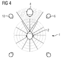
- figure 4
- shows a schematical top view of conversation hearing situation given in
figure 1 , as well as the acoustical localization of the speakers as perceived by the user of the binaural hearing system when applying the method according tofigure 3 . - Parts and variables corresponding to one another are provided with in each case the same reference numerals in all figures.
- In
figure 1 , a schematical top view of a hearing situation 1 corresponding to a conversation is shown. Auser 2 of a state-of-the-art binaural hearing system (not shown) is surrounded by his conversational partners, given by thespeakers - If the state-of-the-art binaural hearing system is applying a noise reduction in which noise from directions other than the one of the target speaker 4, at least partially, is aimed to be reduced via the binaural beamforming of the binaural beamforming system, the target speaker 4 will be perceived by the
user 2 in the proper direction. However, the other,non-target speakers user 2, due to the binaural beamforming may show their binaural cues distorted when talking to theuser 2 which is focused on the target speaker 4, leading to an improper perception of the acoustical localization of thenon-target speakers user 2. - This is displayed schematically in
figure 2 . The attenuation of the signal volume of - possibly occasional - conversational contributions of thenon-target speakers non-target speakers figure 1 . The loss of the binaural cues may lead to a wrong acoustical perception of the positions of thenon-target speakers user 2. This means, theuser 2 can see the actual positions of two interveningnon-target speakers 6, 12 as spatially well separated from the target speaker 4, but due to the state-of-the-art binaural beamforming, displayed by thebeam 14, and the loss of binaural cues of thenon-target speakers 6, 12 caused by the noise reduction processes, theuser 2 "hears" contributions from thenon-target speakers 6, 12 as if those were located much closer to the target speaker 4. - In
figure 3 , amethod 18 for operating abinaural hearing system 20 is illustrated by means of a block diagram. Themethod 18 is particularly useful in order to preserve binaural cues of asound signal 22 when noise reduction is active in thebinaural hearing system 20. Thebinaural hearing system 20 comprises afirst hearing aid 24 and asecond hearing aid 26. In thefirst hearing aid 24, afirst reference signal 28 is generated from thesound signal 22 by afirst microphone 30, while in thesecond hearing aid 26, asecond reference signal 32 is generated from thesound signal 22 by asecond microphone 34. Again in thefirst hearing aid 24, a firstsupplementary signal 36 is generated from thesound signal 22 by a third microphone 38, while in the second hearing aid 26 a secondsupplementary signal 40 is generated from thesound signal 22 by a fourth microphone 42. - The
second reference signal 32 and the secondsupplementary signal 40 are transmitted from thesecond hearing aid 26 to thefirst hearing aid 24. There, thefirst reference signal 28, thesecond reference signal 32, the firstsupplementary signal 36 and the second supplementary signal 42 are transformed into the time-frequency domain by afilter bank 44. After transformation, the signal components of the first and second reference andsupplementary signals binaural beamformer signal 46 together with thefirst reference signal 28 and thesecond reference signal 32 are used to determine acommon gain 48 in each frequency band given by thefilter bank 40. The firstbinaural beamformer signal 46 is used to derive thecommon gain 48 in order to include all possible acoustical information, i.e., also time or level differences that are only measurable with the help of the first and the secondsupplementary signal common gain 48 by the firstbinaural beamformer signal 46. - The
common gain 48 is applied to thefirst reference signal 28 by a mere scalar multiplication to obtain the firstcommon gain signal 50. To the firstbinaural beamformer signal 46, adecomposition 52 is applied in order to decompose the firstbinaural beamformer signal 46 into its magnitude and phase components. To the firstcommon gain signal 50, adecomposition 54 is applied in order to decompose the firstcommon gain signal 50 into at least its magnitude component. If the phase component of the firstcommon gain signal 50 is not further taken into account, thedecomposition 54 can be achieved by merely taking the absolute value of the firstcommon gain signal 50. - The first binaural beam
former signal 46 and the firstcommon gain signal 50 are now compared in a way still to be described. The result of the comparison is ahierarchical classification 56 with respect to noise reduction, i.e., from theclassification 56 quantitative information on whether or not a strong noise reduction is present in the firstbinaural beamformer signal 46 can be obtained. According to theclassification 56, the magnitudes of the firstbinaural beamformer signal 46 and the firstcommon gain signal 50 are mixed in order to derive afirst output signal 58. The phase of thefirst output signal 58 is taken to be thephase 60 of thefirst reference signal 28 or the phase of the firstbinaural beamformer signal 46 according to theclassification 56. Thefirst output signal 58 may be further processes (not shown infigure 3 ) to derive afirst playback signal 62 which is converted into asound signal 64 by afirst loudspeaker 66 of thefirst hearing aid 24. - The magnitude of the
first output signal 58 in a given frequency band and to a time-frequency frame may be taken as a linear mixture
first output signal 58, 1stBinBF the firstbinaural beamformer signal 46, and 1stComG the firstcommon gain signal 50, and |.| denotes the absolute value. - For the classification, if taking signal power as the variable to compare, the mixing factor a may depend on the classification of pow(1stBinBF) and pow(1stComG), where pow(.) denotes the signal power of the argument. E.g., one might take


- If taking the power difference of the first
common gain signal 50 and the firstbinaural beamformer signal 46 as the relevant variable for theclassification 56, one might establish a hierarchy by taking as the upper and lower limit for the power difference diff the maximum and minimum values max(diff), min(diff) over the given time window (e.g., a frame or a sequence of frames) as well as the temporal mean value mean(diff) of the power difference over the time window. For each time window, the power difference diff may attain a value which falls into one of the following four intervals: - 1: [max(diff), max(diff)/2 + mean(diff)/2],
- 2: [max(diff)/2 + mean(diff)/2, mean(diff)],
- 3: [mean(diff), mean(diff)/2 + min(diff)/2],
- 4: [mean(diff)/2 + min(diff)/2, min(diff)].
- To each interval, a different value is assigned to the scalar a in the equation given above for the linear mixture, with the hierarchy a(1)>a(2)>a(3)>a(4).
- The phase of the
first output signal 58 in these examples each time may be given by thephase 60 of thefirst reference signal 28 for lower frequency bands (up to 1.5 kHz or 2 kHz) and by the phase of the firstbinaural beamformer signal 46 otherwise. - If the complexe coherence C is taken as the variable, a threshold T may be taken as the temporal mean of C over the time window. Then, for low frequency bands up to 2 kHz, the magnitude of the
first output signal 58 may be determined according to a = 1 for C < T, a = 0.3 otherwise. For higher frequencies, one might take a = 0.7 for C < T and a = 0.3 otherwise. Other settings for a different from the given examples are possible. In this embodiment, the main idea is that when the condition C < T is met, more magnitude content of the firstbinaural beamformer signal 46 in the lower frequency bands than in the higher frequency bands is processed into thefirst output signal 58. - This approach reflects the fact that most speech energy is concentrated at lower frequencies, so that the spatial preception of an acoustical environment such as hearing situation 1 is typically dominated by the content in the lower frequency bands. Thus, in case the complex coherence C between the first
binaural beamformer signal 46 and the firstcommon gain signal 50 is below a temporal mean value, one may infer that for the short time slot to which the complex coherence is taken, the first binaural beamformer signal 46 - which also indicates the degree of noise reduction by the spatial characteristics of the beam in the given frequency band - differs "more than normal" from the firstcommon gain signal 50. The firstcommon gain signal 50 can be interpreted as a reference of the total signal level at both thefirst hearing aid 24 and thesecond hearing aid 26 in each particular frequency band for the degree of noise reduction present in the firstbinaural beamformer signal 46, while the reference is taken into account via the comparison of C with respect to its the temporal mean T. So an instantaneously "more than normal"-deviation of the firstbinaural beamformer signal 46 from the firstcommon gain signal 50 indicates a higher degree of binaural noise reduction in the former (Question: is that right?). - In this embodiment, the phase of the
first output signal 58 in this example may be given for lower frequency bands (up to 1.5 kHz or 2 kHz) by thephase 60 of thefirst reference signal 28 or by the phase of the firstbinaural beamformer signal 46, depending on the phase angle of C, and only by the phase of the firstbinaural beamformer signal 46 for higher frequencies. - A noise reduction process which is based on a binaural beamforming process suppressing sounds from sound sources located in different directions than the target sound source may distort the binaural cues of non-target sound signals, i.e., sound signal components whose source is not located in the target direction. Even though these sound signals are suppressed by the binaural beamforming anyway, and might not be perceived as "conversationally relevant", they still might have an important impact on the user's 2 perception of the acoustical scene in his hearing environment. Distorted binaural cues of these non-target sound signals then may lead to a mismatch of the acoustical perception of the non-target sound sources and their actual positions as seen by the user. The mixing of the "cues-distorted" first binaural beamformer signal with the "low-noise-reduction" first common gain signal according to the noise reduction present as well as the phase information taken from one hearing aid as the phase in that hearing aid's output signal allows the
user 2 to perceive better level differences, temporal shiftings and delays in order to restore binaural cues. - Thus, as schematically shown in
figure 4 in a top view of the hearing situation 1 given infigure 1 , theuser 2 now acoustically locates thenon-target speakers 6, 12 in the same position with respect to the target speaker 4 as he sees them. - Even though the invention has been illustrated and described in detail with help of a preferred embodiment example, the invention is not restricted by this example. Other variations can be derived by a person skilled in the art without leaving the extent of protection of this invention.
-
- 1
- hearing situation
- 2
- user (of a binaural hearing system)
- 4
- target speaker
- 6-12
- non-target speakers
- 14
- beam
- 18
- method for operating a binaural hearing system
- 20
- binaural hearing system
- 22
- sound signal
- 24
- first hearing aid
- 26
- second hearing aid
- 28
- first reference signal
- 30
- first microphone
- 32
- second reference signal
- 34
- second microphone
- 36
- first supplementary signal
- 38
- third microphone
- 40
- second supplementary signal
- 42
- fourth microphone
- 44
- filter bank
- 46
- first binaural beamformer signal
- 48
- common gain
- 50
- first common gain signal
- 52-54
- decomposition
- 56
- classification
- 58
- first output signal
- 60
- phase of first reference signal
- 62
- first playback signal
- 64
- sound signal
- 66
- first loudspeaker
Claims (12)
- A method (18) for operating a binaural hearing system (20), said binaural hearing system (20) comprising a first hearing aid (24) and a second hearing aid (26),
wherein the first hearing aid (24) generates a first reference signal (28) from a sound signal (22) by a first microphone (30),
wherein the second hearing aid (26) generates a second reference signal (32) from a sound signal (22) by a second microphone (34),
wherein the first reference signal (28) and the second reference signal (32) are both used to derive a first binaural beamformer signal (46) and a second binaural beamformer signal,
wherein the first reference signal (28) and the second reference signal (32) are used to determine a common gain (48), and- from the first reference signal (28) and the common gain (48) a first common gain signal is derived (50), and- from the second reference signal (32) and the common gain (48) a second common gain signal is derived, andwherein at least for a number of frequency bands- the first binaural beamformer signal (46) is compared with the first common gain signal (50) for classification (56) with respect to a noise reduction, and- the first binaural beamformer signal (46) and the first common gain signal (50) are mixed in dependence of said classification (56) in order to obtain a first output signal (58). - The method (18) according to claim 1,
wherein the first binaural beamformer signal (46) is compared to the first common gain signal (50) in a time-frequency domain, and
wherein the first output signal (58) is obtained in the time-frequency domain. - The method (18) according to claim 1 or claim 2,
wherein for the classification (56) of the first binaural beamformer signal (46) and the first common gain signal (58) at least one of the variables signal power, mean signal power and complex coherence function is taken into account. - The method (18) according to one of the preceding claims,
wherein at least for a number of frequency bands,- the common gain (48) is determined in each of said number of frequency bands from the first reference signal (28) in the frequency band and the second reference signal (32) in the frequency band,- the first common gain signal (50) in the frequency band is derived from the common gain (48) in the frequency band and the first reference signal (28) in the frequency band, and- the second common gain signal in the frequency band is derived from the common gain (48) in the frequency band and the second reference signal in the frequency band. - The method (18) according to one of the preceding claims,
wherein in at least one frequency band below 2 kHz a phase of the first output signal (58) is derived from a phase (60) of the first reference signal (28). - The method (18) according to one of the preceding claims,
wherein in at least one frequency band a phase of the first output signal (58) is derived from a phase of the first binaural beamformer signal (46). - The method (18) according to one of the preceding claims,
wherein for said number of frequency bands,- the first binaural beamformer signal (46) and the first common gain signal (50) each are decomposed into a magnitude component and a phase component, and- the magnitude component of the first binaural beamformer signal (46) and the magnitude component of the first common gain signal (50) are mixed in dependence of said classification (56) in order to obtain a magnitude component of the first output signal (58). - The method (18) according to one of the preceding claims,
wherein the first hearing aid (24) generates a first supplementary signal (36) from a sound signal (22) by a third microphone (38),
wherein the second hearing aid (26) generates a second supplementary signal (40) from the sound signal (22) by a fourth microphone (42), and
wherein the first supplementary signal (36) and the second supplementary signal (40) are both taken into account to derive the first binaural beamformer signal (46) and the second binaural beamformer signal. - The method (18) according to claim 8,
wherein the first supplementary signal (36) and the second supplementary signal (40) are taken into account to determine the common gain (48). - The method (18) according to one of the preceding claims,
wherein at least for a number of frequency bands- the second binaural beamformer signal is compared with the second common gain signal for classification with respect to a noise reduction, and- the second binaural beamformer signal and the second common gain signal are mixed in dependence of said classification in order to obtain a second output signal. - The method according to claim 10,
wherein a first playback signal (62) is derived from the first output signal (58) without an additional input of the second output signal into the first playback signal (62), and
wherein the first playback signal (62) is converted into a sound signal (64) by a first loudspeaker (66) of the first hearing aid (24). - A binaural hearing system (20), comprising a first hearing aid (24) and a second hearing aid (26), said binaural hearing system (20) being configured to perform the method (18) according to one of the preceding claims.
Applications Claiming Priority (1)
| Application Number | Priority Date | Filing Date | Title |
|---|---|---|---|
| EP15186710 | 2015-09-24 |
Publications (2)
| Publication Number | Publication Date |
|---|---|
| EP3148217A1 true EP3148217A1 (en) | 2017-03-29 |
| EP3148217B1 EP3148217B1 (en) | 2019-01-09 |
Family
ID=54199594
Family Applications (1)
| Application Number | Title | Priority Date | Filing Date |
|---|---|---|---|
| EP16172902.5A Active EP3148217B1 (en) | 2015-09-24 | 2016-06-03 | Method for operating a binaural hearing system |
Country Status (2)
| Country | Link |
|---|---|
| EP (1) | EP3148217B1 (en) |
| DK (1) | DK3148217T3 (en) |
Cited By (2)
| Publication number | Priority date | Publication date | Assignee | Title |
|---|---|---|---|---|
| US10555094B2 (en) | 2017-03-29 | 2020-02-04 | Gn Hearing A/S | Hearing device with adaptive sub-band beamforming and related method |
| EP3672283A1 (en) * | 2018-12-21 | 2020-06-24 | Sivantos Pte. Ltd. | Method for improving the spatial hearing perception of a binaural hearing aid |
Citations (5)
| Publication number | Priority date | Publication date | Assignee | Title |
|---|---|---|---|---|
| US20040252852A1 (en) * | 2000-07-14 | 2004-12-16 | Taenzer Jon C. | Hearing system beamformer |
| WO2007028250A2 (en) * | 2005-09-09 | 2007-03-15 | Mcmaster University | Method and device for binaural signal enhancement |
| US20100002886A1 (en) * | 2006-05-10 | 2010-01-07 | Phonak Ag | Hearing system and method implementing binaural noise reduction preserving interaural transfer functions |
| EP2347603A1 (en) * | 2008-11-05 | 2011-07-27 | Hear Ip Pty Ltd | A system and method for producing a directional output signal |
| EP2884763A1 (en) * | 2013-12-13 | 2015-06-17 | GN Netcom A/S | A headset and a method for audio signal processing |
-
2016
- 2016-06-03 EP EP16172902.5A patent/EP3148217B1/en active Active
- 2016-06-03 DK DK16172902.5T patent/DK3148217T3/en active
Patent Citations (5)
| Publication number | Priority date | Publication date | Assignee | Title |
|---|---|---|---|---|
| US20040252852A1 (en) * | 2000-07-14 | 2004-12-16 | Taenzer Jon C. | Hearing system beamformer |
| WO2007028250A2 (en) * | 2005-09-09 | 2007-03-15 | Mcmaster University | Method and device for binaural signal enhancement |
| US20100002886A1 (en) * | 2006-05-10 | 2010-01-07 | Phonak Ag | Hearing system and method implementing binaural noise reduction preserving interaural transfer functions |
| EP2347603A1 (en) * | 2008-11-05 | 2011-07-27 | Hear Ip Pty Ltd | A system and method for producing a directional output signal |
| EP2884763A1 (en) * | 2013-12-13 | 2015-06-17 | GN Netcom A/S | A headset and a method for audio signal processing |
Non-Patent Citations (4)
| Title |
|---|
| CORNELIS B ET AL: "Theoretical Analysis of Binaural Multimicrophone Noise Reduction Techniques", IEEE TRANSACTIONS ON AUDIO, SPEECH AND LANGUAGE PROCESSING, IEEE, vol. 18, no. 2, 1 February 2010 (2010-02-01), pages 342 - 355, XP011329133, ISSN: 1558-7916, DOI: 10.1109/TASL.2009.2028374 * |
| HIROSHI SARUWATARI ET AL: "Binaural Hearing Aid Using Sound-Localization-Preserved MMSE STSA Estimator with ICA-Based Noise Estimation", 31 December 2010 (2010-12-31), XP055342208, Retrieved from the Internet <URL:http://www.iwaenc.org/proceedings/2010/HTML/Uploads/1058.pdf> [retrieved on 20170203] * |
| HOMAYOUN KAMKAR-PARSI A ET AL: "Instantaneous Binaural Target PSD Estimation for Hearing Aid Noise Reduction in Complex Acoustic Environments", IEEE TRANSACTIONS ON INSTRUMENTATION AND MEASUREMENT, IEEE SERVICE CENTER, PISCATAWAY, NJ, US, vol. 60, no. 4, 1 April 2011 (2011-04-01), pages 1141 - 1154, XP011349547, ISSN: 0018-9456, DOI: 10.1109/TIM.2010.2084690 * |
| LOTTER ET AL: "Dual-Channel Speech Enhancement By Superdirective Beamforming", EURASIP JOURNAL OF APPLIED SIGNAL PROCESSING, HINDAWI PUBLISHING CO., CUYAHOGA FALLS, OH, US, vol. 2006, 1 January 2006 (2006-01-01), pages 1 - 14, XP007915506, ISSN: 1110-8657, DOI: 10.1155/ASP/2006/63297 * |
Cited By (5)
| Publication number | Priority date | Publication date | Assignee | Title |
|---|---|---|---|---|
| US10555094B2 (en) | 2017-03-29 | 2020-02-04 | Gn Hearing A/S | Hearing device with adaptive sub-band beamforming and related method |
| EP3672283A1 (en) * | 2018-12-21 | 2020-06-24 | Sivantos Pte. Ltd. | Method for improving the spatial hearing perception of a binaural hearing aid |
| US20200204932A1 (en) * | 2018-12-21 | 2020-06-25 | Sivantos Pte. Ltd. | Method for improving the spatial hearing perception of a binaural hearing aid |
| JP2020102835A (en) * | 2018-12-21 | 2020-07-02 | シバントス ピーティーイー リミテッド | Methods for improving spatial hearing in binaural hearing aids |
| US10848879B2 (en) * | 2018-12-21 | 2020-11-24 | Sivantos Pte. Ltd. | Method for improving the spatial hearing perception of a binaural hearing aid |
Also Published As
| Publication number | Publication date |
|---|---|
| EP3148217B1 (en) | 2019-01-09 |
| DK3148217T3 (en) | 2019-04-15 |
Similar Documents
| Publication | Publication Date | Title |
|---|---|---|
| EP2360943B1 (en) | Beamforming in hearing aids | |
| Van den Bogaert et al. | Speech enhancement with multichannel Wiener filter techniques in multimicrophone binaural hearing aids | |
| Marquardt et al. | Theoretical analysis of linearly constrained multi-channel Wiener filtering algorithms for combined noise reduction and binaural cue preservation in binaural hearing aids | |
| Hadad et al. | The binaural LCMV beamformer and its performance analysis | |
| US9992587B2 (en) | Binaural hearing system configured to localize a sound source | |
| US10003893B2 (en) | Method for operating a binaural hearing system and binaural hearing system | |
| US9613610B2 (en) | Directional sound masking | |
| US8300861B2 (en) | Hearing aid algorithms | |
| EP2563044B1 (en) | A method, a listening device and a listening system for maximizing a better ear effect | |
| Arweiler et al. | The influence of spectral characteristics of early reflections on speech intelligibility | |
| Thiemann et al. | Speech enhancement for multimicrophone binaural hearing aids aiming to preserve the spatial auditory scene | |
| EP2563045A1 (en) | A method and a binaural listening system for maximizing a better ear effect | |
| Marquardt et al. | Interaural coherence preservation for binaural noise reduction using partial noise estimation and spectral postfiltering | |
| EP3672283B1 (en) | Method for improving the spatial hearing perception of a binaural hearing aid | |
| Kates et al. | Integrating a remote microphone with hearing-aid processing | |
| As' ad et al. | A robust target linearly constrained minimum variance beamformer with spatial cues preservation for binaural hearing aids | |
| Marquardt et al. | Optimal binaural LCMV beamformers for combined noise reduction and binaural cue preservation | |
| Xiao et al. | Effect of target signals and delays on spatially selective active noise control for open-fitting hearables | |
| Gößling et al. | Performance analysis of the extended binaural MVDR beamformer with partial noise estimation | |
| Gößling et al. | Binaural LCMV beamforming with partial noise estimation | |
| EP3148217B1 (en) | Method for operating a binaural hearing system | |
| Reindl et al. | Analysis of two generic wiener filtering concepts for binaural speech enhancement in hearing aids | |
| Bissmeyer et al. | Adaptive spatial filtering improves speech reception in noise while preserving binaural cues | |
| Farmani et al. | Sound source localization for hearing aid applications using wireless microphones | |
| As' ad et al. | Binaural beamforming with spatial cues preservation for hearing aids in real-life complex acoustic environments |
Legal Events
| Date | Code | Title | Description |
|---|---|---|---|
| PUAI | Public reference made under article 153(3) epc to a published international application that has entered the european phase |
Free format text: ORIGINAL CODE: 0009012 |
|
| STAA | Information on the status of an ep patent application or granted ep patent |
Free format text: STATUS: THE APPLICATION HAS BEEN PUBLISHED |
|
| AK | Designated contracting states |
Kind code of ref document: A1 Designated state(s): AL AT BE BG CH CY CZ DE DK EE ES FI FR GB GR HR HU IE IS IT LI LT LU LV MC MK MT NL NO PL PT RO RS SE SI SK SM TR |
|
| AX | Request for extension of the european patent |
Extension state: BA ME |
|
| STAA | Information on the status of an ep patent application or granted ep patent |
Free format text: STATUS: REQUEST FOR EXAMINATION WAS MADE |
|
| 17P | Request for examination filed |
Effective date: 20170725 |
|
| RBV | Designated contracting states (corrected) |
Designated state(s): AL AT BE BG CH CY CZ DE DK EE ES FI FR GB GR HR HU IE IS IT LI LT LU LV MC MK MT NL NO PL PT RO RS SE SI SK SM TR |
|
| RIN1 | Information on inventor provided before grant (corrected) |
Inventor name: PUDER, HENNING Inventor name: FISCHER, EGHART Inventor name: BOUCHARD, MARTIN Inventor name: AS AD, HALA Inventor name: KAMKAR-PARSI, HOMAYOUN |
|
| RAP1 | Party data changed (applicant data changed or rights of an application transferred) |
Owner name: SIVANTOS PTE. LTD. |
|
| RIC1 | Information provided on ipc code assigned before grant |
Ipc: H04R 25/00 20060101AFI20180223BHEP Ipc: G10L 21/0216 20130101ALN20180223BHEP |
|
| GRAP | Despatch of communication of intention to grant a patent |
Free format text: ORIGINAL CODE: EPIDOSNIGR1 |
|
| STAA | Information on the status of an ep patent application or granted ep patent |
Free format text: STATUS: GRANT OF PATENT IS INTENDED |
|
| INTG | Intention to grant announced |
Effective date: 20180424 |
|
| RIC1 | Information provided on ipc code assigned before grant |
Ipc: G10L 21/0216 20130101ALN20180413BHEP Ipc: H04R 25/00 20060101AFI20180413BHEP |
|
| GRAJ | Information related to disapproval of communication of intention to grant by the applicant or resumption of examination proceedings by the epo deleted |
Free format text: ORIGINAL CODE: EPIDOSDIGR1 |
|
| STAA | Information on the status of an ep patent application or granted ep patent |
Free format text: STATUS: REQUEST FOR EXAMINATION WAS MADE |
|
| GRAP | Despatch of communication of intention to grant a patent |
Free format text: ORIGINAL CODE: EPIDOSNIGR1 |
|
| STAA | Information on the status of an ep patent application or granted ep patent |
Free format text: STATUS: GRANT OF PATENT IS INTENDED |
|
| INTC | Intention to grant announced (deleted) | ||
| RIC1 | Information provided on ipc code assigned before grant |
Ipc: H04R 25/00 20060101AFI20180712BHEP Ipc: G10L 21/0216 20130101ALN20180712BHEP |
|
| INTG | Intention to grant announced |
Effective date: 20180724 |
|
| GRAS | Grant fee paid |
Free format text: ORIGINAL CODE: EPIDOSNIGR3 |
|
| GRAJ | Information related to disapproval of communication of intention to grant by the applicant or resumption of examination proceedings by the epo deleted |
Free format text: ORIGINAL CODE: EPIDOSDIGR1 |
|
| GRAL | Information related to payment of fee for publishing/printing deleted |
Free format text: ORIGINAL CODE: EPIDOSDIGR3 |
|
| STAA | Information on the status of an ep patent application or granted ep patent |
Free format text: STATUS: REQUEST FOR EXAMINATION WAS MADE |
|
| GRAR | Information related to intention to grant a patent recorded |
Free format text: ORIGINAL CODE: EPIDOSNIGR71 |
|
| STAA | Information on the status of an ep patent application or granted ep patent |
Free format text: STATUS: GRANT OF PATENT IS INTENDED |
|
| GRAA | (expected) grant |
Free format text: ORIGINAL CODE: 0009210 |
|
| STAA | Information on the status of an ep patent application or granted ep patent |
Free format text: STATUS: THE PATENT HAS BEEN GRANTED |
|
| INTC | Intention to grant announced (deleted) | ||
| INTG | Intention to grant announced |
Effective date: 20181129 |
|
| RIC1 | Information provided on ipc code assigned before grant |
Ipc: G10L 21/0216 20130101ALN20181126BHEP Ipc: H04R 25/00 20060101AFI20181126BHEP |
|
| AK | Designated contracting states |
Kind code of ref document: B1 Designated state(s): AL AT BE BG CH CY CZ DE DK EE ES FI FR GB GR HR HU IE IS IT LI LT LU LV MC MK MT NL NO PL PT RO RS SE SI SK SM TR |
|
| REG | Reference to a national code |
Ref country code: GB Ref legal event code: FG4D |
|
| REG | Reference to a national code |
Ref country code: CH Ref legal event code: EP Ref country code: AT Ref legal event code: REF Ref document number: 1088812 Country of ref document: AT Kind code of ref document: T Effective date: 20190115 |
|
| REG | Reference to a national code |
Ref country code: DE Ref legal event code: R096 Ref document number: 602016009119 Country of ref document: DE |
|
| REG | Reference to a national code |
Ref country code: IE Ref legal event code: FG4D |
|
| REG | Reference to a national code |
Ref country code: CH Ref legal event code: NV Representative=s name: E. BLUM AND CO. AG PATENT- UND MARKENANWAELTE , CH |
|
| REG | Reference to a national code |
Ref country code: DK Ref legal event code: T3 Effective date: 20190408 |
|
| REG | Reference to a national code |
Ref country code: NL Ref legal event code: MP Effective date: 20190109 |
|
| REG | Reference to a national code |
Ref country code: LT Ref legal event code: MG4D |
|
| PG25 | Lapsed in a contracting state [announced via postgrant information from national office to epo] |
Ref country code: NL Free format text: LAPSE BECAUSE OF FAILURE TO SUBMIT A TRANSLATION OF THE DESCRIPTION OR TO PAY THE FEE WITHIN THE PRESCRIBED TIME-LIMIT Effective date: 20190109 |
|
| REG | Reference to a national code |
Ref country code: AT Ref legal event code: MK05 Ref document number: 1088812 Country of ref document: AT Kind code of ref document: T Effective date: 20190109 |
|
| PG25 | Lapsed in a contracting state [announced via postgrant information from national office to epo] |
Ref country code: FI Free format text: LAPSE BECAUSE OF FAILURE TO SUBMIT A TRANSLATION OF THE DESCRIPTION OR TO PAY THE FEE WITHIN THE PRESCRIBED TIME-LIMIT Effective date: 20190109 Ref country code: NO Free format text: LAPSE BECAUSE OF FAILURE TO SUBMIT A TRANSLATION OF THE DESCRIPTION OR TO PAY THE FEE WITHIN THE PRESCRIBED TIME-LIMIT Effective date: 20190409 Ref country code: PL Free format text: LAPSE BECAUSE OF FAILURE TO SUBMIT A TRANSLATION OF THE DESCRIPTION OR TO PAY THE FEE WITHIN THE PRESCRIBED TIME-LIMIT Effective date: 20190109 Ref country code: LT Free format text: LAPSE BECAUSE OF FAILURE TO SUBMIT A TRANSLATION OF THE DESCRIPTION OR TO PAY THE FEE WITHIN THE PRESCRIBED TIME-LIMIT Effective date: 20190109 Ref country code: ES Free format text: LAPSE BECAUSE OF FAILURE TO SUBMIT A TRANSLATION OF THE DESCRIPTION OR TO PAY THE FEE WITHIN THE PRESCRIBED TIME-LIMIT Effective date: 20190109 Ref country code: SE Free format text: LAPSE BECAUSE OF FAILURE TO SUBMIT A TRANSLATION OF THE DESCRIPTION OR TO PAY THE FEE WITHIN THE PRESCRIBED TIME-LIMIT Effective date: 20190109 Ref country code: PT Free format text: LAPSE BECAUSE OF FAILURE TO SUBMIT A TRANSLATION OF THE DESCRIPTION OR TO PAY THE FEE WITHIN THE PRESCRIBED TIME-LIMIT Effective date: 20190509 |
|
| PG25 | Lapsed in a contracting state [announced via postgrant information from national office to epo] |
Ref country code: LV Free format text: LAPSE BECAUSE OF FAILURE TO SUBMIT A TRANSLATION OF THE DESCRIPTION OR TO PAY THE FEE WITHIN THE PRESCRIBED TIME-LIMIT Effective date: 20190109 Ref country code: RS Free format text: LAPSE BECAUSE OF FAILURE TO SUBMIT A TRANSLATION OF THE DESCRIPTION OR TO PAY THE FEE WITHIN THE PRESCRIBED TIME-LIMIT Effective date: 20190109 Ref country code: GR Free format text: LAPSE BECAUSE OF FAILURE TO SUBMIT A TRANSLATION OF THE DESCRIPTION OR TO PAY THE FEE WITHIN THE PRESCRIBED TIME-LIMIT Effective date: 20190410 Ref country code: BG Free format text: LAPSE BECAUSE OF FAILURE TO SUBMIT A TRANSLATION OF THE DESCRIPTION OR TO PAY THE FEE WITHIN THE PRESCRIBED TIME-LIMIT Effective date: 20190409 Ref country code: IS Free format text: LAPSE BECAUSE OF FAILURE TO SUBMIT A TRANSLATION OF THE DESCRIPTION OR TO PAY THE FEE WITHIN THE PRESCRIBED TIME-LIMIT Effective date: 20190509 Ref country code: HR Free format text: LAPSE BECAUSE OF FAILURE TO SUBMIT A TRANSLATION OF THE DESCRIPTION OR TO PAY THE FEE WITHIN THE PRESCRIBED TIME-LIMIT Effective date: 20190109 |
|
| REG | Reference to a national code |
Ref country code: DE Ref legal event code: R097 Ref document number: 602016009119 Country of ref document: DE |
|
| PG25 | Lapsed in a contracting state [announced via postgrant information from national office to epo] |
Ref country code: AT Free format text: LAPSE BECAUSE OF FAILURE TO SUBMIT A TRANSLATION OF THE DESCRIPTION OR TO PAY THE FEE WITHIN THE PRESCRIBED TIME-LIMIT Effective date: 20190109 Ref country code: AL Free format text: LAPSE BECAUSE OF FAILURE TO SUBMIT A TRANSLATION OF THE DESCRIPTION OR TO PAY THE FEE WITHIN THE PRESCRIBED TIME-LIMIT Effective date: 20190109 Ref country code: SK Free format text: LAPSE BECAUSE OF FAILURE TO SUBMIT A TRANSLATION OF THE DESCRIPTION OR TO PAY THE FEE WITHIN THE PRESCRIBED TIME-LIMIT Effective date: 20190109 Ref country code: IT Free format text: LAPSE BECAUSE OF FAILURE TO SUBMIT A TRANSLATION OF THE DESCRIPTION OR TO PAY THE FEE WITHIN THE PRESCRIBED TIME-LIMIT Effective date: 20190109 Ref country code: EE Free format text: LAPSE BECAUSE OF FAILURE TO SUBMIT A TRANSLATION OF THE DESCRIPTION OR TO PAY THE FEE WITHIN THE PRESCRIBED TIME-LIMIT Effective date: 20190109 Ref country code: CZ Free format text: LAPSE BECAUSE OF FAILURE TO SUBMIT A TRANSLATION OF THE DESCRIPTION OR TO PAY THE FEE WITHIN THE PRESCRIBED TIME-LIMIT Effective date: 20190109 Ref country code: RO Free format text: LAPSE BECAUSE OF FAILURE TO SUBMIT A TRANSLATION OF THE DESCRIPTION OR TO PAY THE FEE WITHIN THE PRESCRIBED TIME-LIMIT Effective date: 20190109 |
|
| PLBE | No opposition filed within time limit |
Free format text: ORIGINAL CODE: 0009261 |
|
| STAA | Information on the status of an ep patent application or granted ep patent |
Free format text: STATUS: NO OPPOSITION FILED WITHIN TIME LIMIT |
|
| 26N | No opposition filed |
Effective date: 20191010 |
|
| PG25 | Lapsed in a contracting state [announced via postgrant information from national office to epo] |
Ref country code: MC Free format text: LAPSE BECAUSE OF FAILURE TO SUBMIT A TRANSLATION OF THE DESCRIPTION OR TO PAY THE FEE WITHIN THE PRESCRIBED TIME-LIMIT Effective date: 20190109 |
|
| PG25 | Lapsed in a contracting state [announced via postgrant information from national office to epo] |
Ref country code: SI Free format text: LAPSE BECAUSE OF FAILURE TO SUBMIT A TRANSLATION OF THE DESCRIPTION OR TO PAY THE FEE WITHIN THE PRESCRIBED TIME-LIMIT Effective date: 20190109 |
|
| REG | Reference to a national code |
Ref country code: BE Ref legal event code: MM Effective date: 20190630 |
|
| PG25 | Lapsed in a contracting state [announced via postgrant information from national office to epo] |
Ref country code: TR Free format text: LAPSE BECAUSE OF FAILURE TO SUBMIT A TRANSLATION OF THE DESCRIPTION OR TO PAY THE FEE WITHIN THE PRESCRIBED TIME-LIMIT Effective date: 20190109 |
|
| PG25 | Lapsed in a contracting state [announced via postgrant information from national office to epo] |
Ref country code: IE Free format text: LAPSE BECAUSE OF NON-PAYMENT OF DUE FEES Effective date: 20190603 |
|
| PG25 | Lapsed in a contracting state [announced via postgrant information from national office to epo] |
Ref country code: BE Free format text: LAPSE BECAUSE OF NON-PAYMENT OF DUE FEES Effective date: 20190630 Ref country code: LU Free format text: LAPSE BECAUSE OF NON-PAYMENT OF DUE FEES Effective date: 20190603 |
|
| PG25 | Lapsed in a contracting state [announced via postgrant information from national office to epo] |
Ref country code: CY Free format text: LAPSE BECAUSE OF FAILURE TO SUBMIT A TRANSLATION OF THE DESCRIPTION OR TO PAY THE FEE WITHIN THE PRESCRIBED TIME-LIMIT Effective date: 20190109 |
|
| PG25 | Lapsed in a contracting state [announced via postgrant information from national office to epo] |
Ref country code: SM Free format text: LAPSE BECAUSE OF FAILURE TO SUBMIT A TRANSLATION OF THE DESCRIPTION OR TO PAY THE FEE WITHIN THE PRESCRIBED TIME-LIMIT Effective date: 20190109 |
|
| PG25 | Lapsed in a contracting state [announced via postgrant information from national office to epo] |
Ref country code: HU Free format text: LAPSE BECAUSE OF FAILURE TO SUBMIT A TRANSLATION OF THE DESCRIPTION OR TO PAY THE FEE WITHIN THE PRESCRIBED TIME-LIMIT; INVALID AB INITIO Effective date: 20160603 Ref country code: MT Free format text: LAPSE BECAUSE OF FAILURE TO SUBMIT A TRANSLATION OF THE DESCRIPTION OR TO PAY THE FEE WITHIN THE PRESCRIBED TIME-LIMIT Effective date: 20190109 |
|
| PG25 | Lapsed in a contracting state [announced via postgrant information from national office to epo] |
Ref country code: MK Free format text: LAPSE BECAUSE OF FAILURE TO SUBMIT A TRANSLATION OF THE DESCRIPTION OR TO PAY THE FEE WITHIN THE PRESCRIBED TIME-LIMIT Effective date: 20190109 |
|
| PGFP | Annual fee paid to national office [announced via postgrant information from national office to epo] |
Ref country code: DE Payment date: 20250520 Year of fee payment: 10 |
|
| PGFP | Annual fee paid to national office [announced via postgrant information from national office to epo] |
Ref country code: GB Payment date: 20250520 Year of fee payment: 10 Ref country code: DK Payment date: 20250520 Year of fee payment: 10 |
|
| PGFP | Annual fee paid to national office [announced via postgrant information from national office to epo] |
Ref country code: FR Payment date: 20250520 Year of fee payment: 10 |
|
| PGFP | Annual fee paid to national office [announced via postgrant information from national office to epo] |
Ref country code: CH Payment date: 20250701 Year of fee payment: 10 |