EP3148011A1 - Electrical cage member having standoff features - Google Patents
Electrical cage member having standoff features Download PDFInfo
- Publication number
- EP3148011A1 EP3148011A1 EP16189349.0A EP16189349A EP3148011A1 EP 3148011 A1 EP3148011 A1 EP 3148011A1 EP 16189349 A EP16189349 A EP 16189349A EP 3148011 A1 EP3148011 A1 EP 3148011A1
- Authority
- EP
- European Patent Office
- Prior art keywords
- pluggable module
- cage member
- standoff features
- port
- electrical connector
- Prior art date
- Legal status (The legal status is an assumption and is not a legal conclusion. Google has not performed a legal analysis and makes no representation as to the accuracy of the status listed.)
- Withdrawn
Links
- 230000013011 mating Effects 0.000 claims abstract description 20
- 230000017525 heat dissipation Effects 0.000 claims description 27
- 239000004020 conductor Substances 0.000 claims description 2
- 238000001816 cooling Methods 0.000 description 7
- 239000002184 metal Substances 0.000 description 4
- 229910052751 metal Inorganic materials 0.000 description 4
- 238000000034 method Methods 0.000 description 3
- 230000003287 optical effect Effects 0.000 description 3
- 239000000835 fiber Substances 0.000 description 2
- RYGMFSIKBFXOCR-UHFFFAOYSA-N Copper Chemical compound [Cu] RYGMFSIKBFXOCR-UHFFFAOYSA-N 0.000 description 1
- 230000000712 assembly Effects 0.000 description 1
- 238000000429 assembly Methods 0.000 description 1
- 230000005540 biological transmission Effects 0.000 description 1
- 229910052802 copper Inorganic materials 0.000 description 1
- 239000010949 copper Substances 0.000 description 1
- 238000000605 extraction Methods 0.000 description 1
- 239000007769 metal material Substances 0.000 description 1
Images

Classifications
-
- H—ELECTRICITY
- H01—ELECTRIC ELEMENTS
- H01R—ELECTRICALLY-CONDUCTIVE CONNECTIONS; STRUCTURAL ASSOCIATIONS OF A PLURALITY OF MUTUALLY-INSULATED ELECTRICAL CONNECTING ELEMENTS; COUPLING DEVICES; CURRENT COLLECTORS
- H01R13/00—Details of coupling devices of the kinds covered by groups H01R12/70 or H01R24/00 - H01R33/00
- H01R13/648—Protective earth or shield arrangements on coupling devices, e.g. anti-static shielding
- H01R13/658—High frequency shielding arrangements, e.g. against EMI [Electro-Magnetic Interference] or EMP [Electro-Magnetic Pulse]
- H01R13/6581—Shield structure
- H01R13/659—Shield structure with plural ports for distinct connectors
-
- H—ELECTRICITY
- H01—ELECTRIC ELEMENTS
- H01R—ELECTRICALLY-CONDUCTIVE CONNECTIONS; STRUCTURAL ASSOCIATIONS OF A PLURALITY OF MUTUALLY-INSULATED ELECTRICAL CONNECTING ELEMENTS; COUPLING DEVICES; CURRENT COLLECTORS
- H01R13/00—Details of coupling devices of the kinds covered by groups H01R12/70 or H01R24/00 - H01R33/00
- H01R13/648—Protective earth or shield arrangements on coupling devices, e.g. anti-static shielding
- H01R13/658—High frequency shielding arrangements, e.g. against EMI [Electro-Magnetic Interference] or EMP [Electro-Magnetic Pulse]
- H01R13/6581—Shield structure
-
- H—ELECTRICITY
- H01—ELECTRIC ELEMENTS
- H01R—ELECTRICALLY-CONDUCTIVE CONNECTIONS; STRUCTURAL ASSOCIATIONS OF A PLURALITY OF MUTUALLY-INSULATED ELECTRICAL CONNECTING ELEMENTS; COUPLING DEVICES; CURRENT COLLECTORS
- H01R13/00—Details of coupling devices of the kinds covered by groups H01R12/70 or H01R24/00 - H01R33/00
- H01R13/648—Protective earth or shield arrangements on coupling devices, e.g. anti-static shielding
- H01R13/658—High frequency shielding arrangements, e.g. against EMI [Electro-Magnetic Interference] or EMP [Electro-Magnetic Pulse]
- H01R13/6591—Specific features or arrangements of connection of shield to conductive members
- H01R13/6594—Specific features or arrangements of connection of shield to conductive members the shield being mounted on a PCB and connected to conductive members
-
- H—ELECTRICITY
- H01—ELECTRIC ELEMENTS
- H01R—ELECTRICALLY-CONDUCTIVE CONNECTIONS; STRUCTURAL ASSOCIATIONS OF A PLURALITY OF MUTUALLY-INSULATED ELECTRICAL CONNECTING ELEMENTS; COUPLING DEVICES; CURRENT COLLECTORS
- H01R27/00—Coupling parts adapted for co-operation with two or more dissimilar counterparts
-
- H—ELECTRICITY
- H05—ELECTRIC TECHNIQUES NOT OTHERWISE PROVIDED FOR
- H05K—PRINTED CIRCUITS; CASINGS OR CONSTRUCTIONAL DETAILS OF ELECTRIC APPARATUS; MANUFACTURE OF ASSEMBLAGES OF ELECTRICAL COMPONENTS
- H05K7/00—Constructional details common to different types of electric apparatus
- H05K7/20—Modifications to facilitate cooling, ventilating, or heating
- H05K7/20009—Modifications to facilitate cooling, ventilating, or heating using a gaseous coolant in electronic enclosures
- H05K7/20127—Natural convection
-
- G—PHYSICS
- G02—OPTICS
- G02B—OPTICAL ELEMENTS, SYSTEMS OR APPARATUS
- G02B6/00—Light guides; Structural details of arrangements comprising light guides and other optical elements, e.g. couplings
- G02B6/24—Coupling light guides
- G02B6/42—Coupling light guides with opto-electronic elements
- G02B6/4201—Packages, e.g. shape, construction, internal or external details
- G02B6/4274—Electrical aspects
- G02B6/4284—Electrical aspects of optical modules with disconnectable electrical connectors
-
- H—ELECTRICITY
- H01—ELECTRIC ELEMENTS
- H01R—ELECTRICALLY-CONDUCTIVE CONNECTIONS; STRUCTURAL ASSOCIATIONS OF A PLURALITY OF MUTUALLY-INSULATED ELECTRICAL CONNECTING ELEMENTS; COUPLING DEVICES; CURRENT COLLECTORS
- H01R2201/00—Connectors or connections adapted for particular applications
- H01R2201/04—Connectors or connections adapted for particular applications for network, e.g. LAN connectors
Definitions
- the invention relates to an electrical connector assembly for high speed optical and electrical communication systems.
- GBIC gigabit interface converter
- SOC serial optical converter
- thermal cooling is achieved by using a heat sink and/or airflow over the outside of the shielding metal cage surrounding the receptacles.
- thermal cooling provided by conventional designs is proving to be inadequate.
- Some cage designs allow airflow within the metal cage; however the various components within the cage, such as the port separator and receptacle connector, block or restrict airflow.
- an electrical connector assembly comprises a cage member having a plurality of walls comprising side walls and an end wall between the side walls defining a port configured to receive a pluggable module therein through a front end of the cage member.
- the cage member houses a communication connector at a rear end of the cage member configured to be electrically connected to the pluggable module.
- the port has an airflow channel along the end wall allowing airflow through the port between the front end and the rear end along the pluggable module.
- the walls are manufactured from a conductive material and provide electrical shielding for the pluggable module.
- Standoff features extend into the airflow channel from at least one of the end wall and the side walls. The standoff features are configured to engage the pluggable module and locate the pluggable module relative to the communication connector for mating thereto and locate the pluggable module relative to the airflow channel.
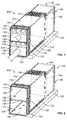
- FIG 1 is a front perspective view of an electrical connector assembly 100 formed in accordance with an exemplary embodiment showing pluggable modules 106 loaded into a cage member 102.
- Figure 2 is a front perspective view of the electrical connector assembly 100 without the pluggable modules 106.
- the electrical connector assembly 100 includes the cage member 102 and a communication connector 104 (shown schematically in Figures 1 and 2 , also illustrated in Figure 3 ) received in the cage member 102.
- the pluggable modules 106 are configured to be loaded into the cage member 102 for mating with the communication connector 104.
- the cage member 102 and communication connector 104 are intended for placement on and electrical connection to a circuit board 107, such as a motherboard.
- the communication connector 104 is arranged within the cage member 102 for mating engagement with the pluggable modules 106.
- the cage member 102 is a shielding, stamped and formed cage member that includes a plurality of shielding walls 108 that define multiple ports 110, 112 for receipt of the pluggable modules 106.
- the cage member 102 constitutes a stacked cage member having the ports 110, 112 in a stacked configuration.
- the port 110 defines an upper port positioned above the port 112 and may be referred to hereinafter as upper port 110.
- the port 112 defines a lower port positioned below the port 110 and may be referred to hereinafter as lower port 112. Any number of ports may be provided in alternative embodiments.
- the cage member 102 includes the ports 110, 112 arranged in a single column, however, the cage member 102 may include multiple columns of ports 110, 112 in alternative embodiments (for example, 2X2, 3X2, 4X2, 4X3, etc.). Additionally, while the cage member 102 is illustrated as a stacked cage member, the cage member 102 may be a single high cage member in alternative embodiments having a single port or a single row of ports rather than stacked ports.
- the cage member 102 includes a top wall 114, a bottom wall 116, a rear wall 118 and side walls 120, 122, which together define the general enclosure or outer perimeter for the cage member 102.
- the walls 108 may be interior divider walls defining side walls 120 or 122 for two different columns of ports 110, 112.
- the top wall 114 may be non-planar and may be stepped downward at the rear, such as above the communication connector 104 (for example, rearward of the pluggable module 106), to improve airflow through the cage member 102.
- the cage member 102 extends between a front end 124 and a rear end 126.
- the communication connector 104 may be positioned at or near the rear end 126 of the cage member 102.
- the pluggable modules 106 are configured to be loaded into the ports 110, 112 through the front end 124.
- at least a portion of the bottom wall 116 may be open to allow the communication connector 104 to interface with the circuit board 107.
- the walls 108 may include a plurality of airflow openings or channels to allow airflow therethrough, such as from front to back, back to front and/or side to side.
- the airflow openings help cool the walls 108, the ports 110, 112 and/or the pluggable modules 106.
- the airflow openings may have any size and shape.
- the size, shape, spacing and/or positioning of the airflow openings may be selected with consideration to thermal performance, shielding performance (for example electromagnetic interference (EMI) shielding), electrical performance, or other design considerations.
- the stepped portion of the top wall 114 may include airflow openings.
- the cage member 102 is subdivided by one or more divider walls 130.
- the divider wall 130 extends horizontally between the side walls 120, 122.
- the divider wall 130 separates the upper port 110 from the lower port 112.
- the divider wall 130 may be a single, planar wall.
- the divider wall 130 may be U-shaped having two parallel walls with a joining wall therebetween at the front end 124 and having a channel between the two parallel walls, such channel allowing airflow between the upper and lower ports 110, 112 and/or for routing light pipes or other components.
- the top wall 114, bottom wall 116 and divider walls 130 define end walls which are provided at top or bottom ends of the ports 110, 112.
- the walls 114, 116, 130 may be referred to generally as end walls 132 or individually as a top end wall 114 or bottom end wall 130 of the upper port 110, or a top end wall 130 or bottom end wall 116 of the lower port 112.
- airflow channels may be defined along some or all of the end walls 132, such as along the top end wall 114 and the top end wall 130 for the upper and lower ports 110, 112, respectively, as in the illustrated embodiment.
- airflow channels may additionally or alternatively be defined along the bottom end wall 130 and the bottom end wall 116 of the upper and lower ports 110, 112, respectively.
- the cage member may be oriented (for example, rotated 90° from the orientation shown) such that the end walls are not at the top and bottom, but rather the side walls are at the top and the bottom.
- the divider wall 130 may be approximately centered between the top wall 114 and the bottom wall 116. Alternatively, the divider wall 130 may be positioned closer to the top wall 114 than the bottom wall 116 such that the lower port 112 is taller than the upper port 110. As such, the lower port 112 allows more airflow therethrough than the upper port 110 for cooling the pluggable module 106 in the lower port 112. For example, because the upper port 110 has more exterior wall surface area for heat dissipation (for example, the top wall 114 is exposed to the exterior environment for cooling or dissipating heat into the ambient environment), the upper port 110 is naturally cooler than the lower port 112.
- the cage member 102 includes standoff features 140 extending from at least one of the walls 108.
- the standoff features 140 may extend from at least one of the end walls 114, 116, 130.
- the standoff features 140 may extend from at least one of the side walls 120, 122.
- the standoff features 140 engage the pluggable module 106 and may locate the pluggable module 106 relative to the communication connector 104 for mating thereto.
- the standoff features 140 may locate the pluggable module 106 relative to airflow channels 142, 144 (shown in Figure 1 ) in the corresponding port 110, 112 to hold the pluggable module 106 in position in the ports 110, 112 such that the pluggable module 106 does not completely block the airflow channel 142, 144.
- the standoff features 140 may hold the pluggable module 106 away from one of the end walls 130 to define an unobstructed portion of the airflow channel 142, 144.
- the standoff features 140 may hold the pluggable modules 106 toward the bottom of the corresponding ports 110, 112 such that the pluggable modules 106 do not touch the tops of the corresponding ports 110, 112, or vice versa.
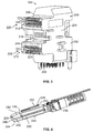
- FIG 3 is a front perspective view of the communication connector 104 in accordance with an exemplary embodiment.
- the communication connector 104 includes a housing 200 defined by an upstanding body portion 202 having sides 204, 206, a lower face 208 configured to be mounted to the circuit board 107 (shown in Figure 1 ), and a mating face 210.
- Upper and lower extension portions 212 and 214 extend from the body portion 202 to define a stepped mating face 210.
- a recessed face 216 is defined between the upper and lower extension portions 212, 214 at the mating face 210 of the body portion 202.
- Circuit card receiving slots 220 and 222 extend inwardly from the mating face 210 of each of the respective upper and lower extension portions 212, 214, and extend inwardly to the body portion 202.
- the circuit card receiving slots 220, 222 are configured to receive card edges of circuit cards of the corresponding pluggable modules 106 (shown in Figure 4 ).
- a plurality of contacts 224 are held by the housing 200 and are exposed within the circuit card receiving slots 220, 222 for mating with the corresponding pluggable module 106.
- the contacts 224 and circuit card receiving slots 220, 222 define first and second mating interfaces 226, 228, respectively, of the communication connector 104.
- the contacts 224 extend from the lower face 208 for termination to the circuit board 107.
- the ends of the contacts 224 may constitute pins that are loaded into plated vias of the motherboard.
- the contacts 224 may be terminated to the circuit board 107 in another manner, such as by surface mounting to the circuit board 107.
- FIG 4 illustrates an exemplary embodiment of the pluggable module 106 for use with electrical connector assembly 100 (shown in Figure 1 ).
- the pluggable module 106 constitutes a small form-factor pluggable (SFP) module; however other types of pluggable modules or transceivers may be used in alternative embodiments.
- the pluggable module 106 includes a conductive body, such as a metal body, or shell 230 holding a circuit card 232 at a mating end 234 thereof for interconnection into one of the slots 220 or 222 (shown in Figure 3 ) of the communication connector 104 (shown in Figure 3 ).
- the shell 230 has a top 240, a bottom 242 and sides 244, 246 between the top 240 and the bottom 242.
- the pluggable module 106 may include thermal interface features 248 configured to provide a thermal interface with the cage member 102 (shown in Figure 1 ), such as for direct thermal contact or communication with the cage member 102.
- the thermal interface features 248 are heat dissipation fins and may be referred to hereinafter as heat dissipation fins 248.
- the heat dissipation fins 248 may extend from any portion of the shell 230, such as the top 240, the bottom 242 and/or the sides 244.
- the shell 230 is thermally conductive, such as a metal material, and the heat dissipation fins 248 dissipate heat from the shell 230.
- the heat dissipation fins 248 extend longitudinally at least partially between the mating end 234 and the opposite end 236 of the shell 230.
- the heat dissipation fins 248 define channels 250 between the heat dissipation fins 248 that allow airflow along the shell 230 and the heat dissipation fins 248, which cools the pluggable module 106.
- the heat dissipation fins 248 have outer edges 252. The outer edges 252 may be configured to engage portions of the cage member 102 when loaded therein. In alternative embodiments, the pluggable module 106 may not include heat dissipation fins.
- the pluggable module may include a latching feature for securing the pluggable module 106 in the cage member 102.
- the latching feature may be releasable for extraction of the pluggable module 106.
- Other types of pluggable modules or transceivers may be utilized in alternative embodiments.
- the standoff features 140 may engage corresponding heat dissipation fins 248 to hold the heat dissipation fins 248 and the pluggable modules 106 off of the end walls 132 (for example, the top wall 114 and the divider wall 130 of the upper and lower ports 110, 112, respectively).
- the heat dissipation fins 248 may engage the shells 230 of the pluggable modules 106 rather than the heat dissipation fins 248.
- the standoff features 140 hold the pluggable modules 106 remote from the end walls 132 such that the airflow channels 142, 144 are located between the pluggable modules 106 and the corresponding end walls 132.
- the standoff features 140 may engage the heat dissipation fins 248 of the pluggable modules 106 to hold the heat dissipation fins 248 a distance from the corresponding end wall 132 such that at least a portion of the airflow channel 142, 144 is located above the heat dissipation fins 248.
- the standoff features 140 may align the pluggable modules 106 in the ports 110, 112 with the mating interfaces 226, 228 ( Figure 6 ) of the communication connector 104 for mating with the communication connector 104.
- the standoff features 140 associated with the different ports 110, 112 may have different sizes, such as to position the pluggable modules 106 at different heights within the ports 110, 112, to accommodate different sized pluggable modules 106 and/or to define different sized airflow channels 142, 144.
- the lower port 112 may be taller than the upper port 110 to allow greater airflow through the lower port 112 than through the upper port 110 for better cooling of the pluggable module 106 in the lower port 112.
- the standoff features 140 associated with the lower port 112 may be longer than the standoff features 140 associated with the upper port 110 to define a taller lower port 112 and thus a taller airflow channel 142, 144.
- the upper port 110 may not include any standoff features 140, but rather only the lower port 112 includes standoff features 140.
- the pluggable module 106 in the upper port 110 directly engages the top end wall 114 while the standoff features 140 in the lower port 112 hold the pluggable module 106 away from the divider wall 130.
- the standoff feature 140 may pass through one of the channels 250 between the heat dissipation fins 248 to engage the top 240.
- the standoff features 140 have sides 154 extending between the base 150 and the distal end 152.
- the sides 154 may be angled with a wider base 150 and a narrower distal end 152.
- the standoff features 140 are V-shaped ribs extending longitudinally along the end walls 132 at least partially between the front end 124 and the rear end 126 (shown in Figure 1 ).
- the standoff features 140 may be referred to hereinafter as ribs 140.
- the ribs 140 may extend a majority of a length of the cage member 102 between the front end 124 and the rear end 126. Any number of ribs 140 may be provided; however, in the illustrated embodiment, two ribs 140 are provided proximate to the two side walls 120, 122 that are configured to engage the two outer-most heat dissipation fins 248.
- the standoff features 140 may have other shapes in alternative embodiments.
- the bottoms 242 of the pluggable modules 106 engage the bottom end walls 132 (for example, the divider wall 130 and the bottom wall 116).
- the walls 108 and the standoff features 140 have a tight tolerance to locate the pluggable modules 106 (for example, side-to-side and top-to-bottom) within the ports 110, 112 for mating with the communication connector 104.
- the bottom end walls 132 may additionally or alternatively include the standoff features 140 to define airflow channels beneath the pluggable modules 106.
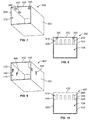
- FIG 7 is a front perspective view of a cage member 302 formed in accordance with an exemplary embodiment.
- Figure 8 is a front view of the cage member 302 with the pluggable module 106 loaded therein.
- the cage member 302 is similar to the cage member 102 (shown in Figure 1 ); however the cage member 302 is a single port cage member rather than a stacked or multi-port cage member. Additionally, the cage member 302 includes standoff features 340 that are shaped differently than the standoff features 140 (shown in Figure 6 ).
- the standoff features 340 are protrusions extending from an end wall 332 of the cage member 302.
- the standoff features 340 may be referred to hereinafter as protrusions 340.
- the protrusions 340 are conical shaped; however, the protrusions 340 may have other shapes in alternative embodiments.
- the standoff features 340 are integral with the end wall 332 and may be formed by drawing, swaging, coining or other forming processes.
- the standoff features 340 are arranged in rows, such as a first row proximate to a first side wall 320 and a second row proximate to a second side wall 322.
- the standoff features 340 are configured to be aligned with different heat dissipation fins 248 ( Figure 8 ) of the pluggable module 106. Any number of standoff features 340 may be provided.
- the standoff features 340 locate the pluggable module 106 in a port 310 of the cage member 302.
- the standoff features 340 may locate the pluggable module 106 within the port 310 to define an airflow channel therein, such as along the end wall 332.
- the standoff features 340 hold the pluggable module 106 clear of such airflow channel such that at least a portion of the airflow channel is unobstructed by the pluggable module 106.
- the standoff features 340 may hold the pluggable module 106 away from the end wall 332 to define the unobstructed portion of the airflow channel.
- FIG 9 is a front perspective view of a cage member 402 formed in accordance with an exemplary embodiment.
- Figure 10 is a front view of the cage member 402 with the pluggable module 106 loaded therein.
- the cage member 402 is similar to the cage member 102 (shown in Figure 1 ); however the cage member 402 is a single port cage member rather than a stacked or multi-port cage member.
- the cage member 402 includes standoff features 440 that are shaped differently than the standoff features 140 (shown in Figure 6 ) and that are located along side walls 420, 422 of the cage member 402 rather than along an end wall 432 of the cage member 402.
- the standoff features 440 are rails extending from the side walls 420, 422 of the cage member 402. Any number of standoff features 440 may be provided.
- the standoff features 440 may be referred to hereinafter as rails 440.
- the rails 440 are stamped from the side walls 420, 422 and bent or formed into a port 410 of the cage member 402.
- the rails 440 are integral with the side walls 420, 422.
- the rails 440 are configured to engage the top 240 of the pluggable module 106 and hold the pluggable module 106 in the port 410.
- the airflow channel of the port 410 is defined above the rails 440.
Landscapes
- Engineering & Computer Science (AREA)
- Microelectronics & Electronic Packaging (AREA)
- Physics & Mathematics (AREA)
- Thermal Sciences (AREA)
- Optical Couplings Of Light Guides (AREA)
- Cooling Or The Like Of Electrical Apparatus (AREA)
- General Physics & Mathematics (AREA)
- Optics & Photonics (AREA)
- Connector Housings Or Holding Contact Members (AREA)
Abstract
Description
- The invention relates to an electrical connector assembly for high speed optical and electrical communication systems.
- It is known to provide a metal cage with a plurality of ports, whereby transceiver modules are pluggable therein. Several pluggable module designs and standards have been introduced in which a pluggable module plugs into a receptacle which is electronically connected to a host circuit board. For example, a well-known type of transceiver developed by an industry consortium is known as a gigabit interface converter (GBIC) or serial optical converter (SOC) and provides an interface between a computer and a data communication network such as Ethernet or a fiber network. These standards offer a generally robust design which has been well received in industry.
- It is desirable to increase the operating frequency of the network connections. Electrical connector systems that are used at increased operating speeds present a number of design problems, particularly in applications in which data transmission rates are high, for example, in the range above 10 Gbps (Gigabits/second). One concern with such systems is reducing electromagnetic interference (EMI) emissions. Another concern is reducing operating temperatures of the transceivers.
- In conventional designs, thermal cooling is achieved by using a heat sink and/or airflow over the outside of the shielding metal cage surrounding the receptacles. However, the thermal cooling provided by conventional designs is proving to be inadequate. Some cage designs allow airflow within the metal cage; however the various components within the cage, such as the port separator and receptacle connector, block or restrict airflow.
- There is a need for an electrical connector assembly having improved thermal cooling compared to known connector assemblies.
- This problem is solved by an electrical connector assembly according to claim 1.
- According to the invention, an electrical connector assembly comprises a cage member having a plurality of walls comprising side walls and an end wall between the side walls defining a port configured to receive a pluggable module therein through a front end of the cage member. The cage member houses a communication connector at a rear end of the cage member configured to be electrically connected to the pluggable module. The port has an airflow channel along the end wall allowing airflow through the port between the front end and the rear end along the pluggable module. The walls are manufactured from a conductive material and provide electrical shielding for the pluggable module. Standoff features extend into the airflow channel from at least one of the end wall and the side walls. The standoff features are configured to engage the pluggable module and locate the pluggable module relative to the communication connector for mating thereto and locate the pluggable module relative to the airflow channel.
- The invention will now be described by way of example with reference to the accompanying drawings wherein:
-
Figure 1 is a front perspective view of an electrical connector assembly formed in accordance with an exemplary embodiment showing pluggable modules loaded into a cage member. -
Figure 2 is a front perspective view of the electrical connector assembly without the pluggable modules. -
Figure 3 is a front perspective view of a communication connector of the electrical connector assembly. -
Figure 4 illustrates an exemplary embodiment of one of the pluggable modules shown inFigure 1 . -
Figure 5 is a front view of the electrical connector assembly showing the pluggable modules loaded in the cage member. -
Figure 6 is a front view of the electrical connector assembly with the pluggable modules removed to illustrate the cage member and the communication connector. -
Figure 7 is a front perspective view of a cage member formed in accordance with an exemplary embodiment. -
Figure 8 is a front view of the cage member shown inFigure 7 with a pluggable module loaded therein. -
Figure 9 is a front perspective view of a cage member formed in accordance with an exemplary embodiment. -
Figure 10 is a front view of the cage member shown inFigure 9 with a pluggable module loaded therein. -
Figure 1 is a front perspective view of anelectrical connector assembly 100 formed in accordance with an exemplary embodiment showingpluggable modules 106 loaded into acage member 102.Figure 2 is a front perspective view of theelectrical connector assembly 100 without thepluggable modules 106. Theelectrical connector assembly 100 includes thecage member 102 and a communication connector 104 (shown schematically inFigures 1 and 2 , also illustrated inFigure 3 ) received in thecage member 102. Thepluggable modules 106 are configured to be loaded into thecage member 102 for mating with thecommunication connector 104. Thecage member 102 andcommunication connector 104 are intended for placement on and electrical connection to acircuit board 107, such as a motherboard. Thecommunication connector 104 is arranged within thecage member 102 for mating engagement with thepluggable modules 106. - The
cage member 102 is a shielding, stamped and formed cage member that includes a plurality ofshielding walls 108 that definemultiple ports pluggable modules 106. In the illustrated embodiment, thecage member 102 constitutes a stacked cage member having theports port 110 defines an upper port positioned above theport 112 and may be referred to hereinafter asupper port 110. Theport 112 defines a lower port positioned below theport 110 and may be referred to hereinafter aslower port 112. Any number of ports may be provided in alternative embodiments. In the illustrated embodiment, thecage member 102 includes theports cage member 102 may include multiple columns ofports cage member 102 is illustrated as a stacked cage member, thecage member 102 may be a single high cage member in alternative embodiments having a single port or a single row of ports rather than stacked ports. - The
cage member 102 includes atop wall 114, abottom wall 116, arear wall 118 andside walls cage member 102. When ganged in multiple columns ofports walls 108 may be interior divider walls definingside walls ports top wall 114 may be non-planar and may be stepped downward at the rear, such as above the communication connector 104 (for example, rearward of the pluggable module 106), to improve airflow through thecage member 102. - The
cage member 102 extends between afront end 124 and arear end 126. Thecommunication connector 104 may be positioned at or near therear end 126 of thecage member 102. Thepluggable modules 106 are configured to be loaded into theports front end 124. Optionally, at least a portion of thebottom wall 116 may be open to allow thecommunication connector 104 to interface with thecircuit board 107. - In an exemplary embodiment, the
walls 108 may include a plurality of airflow openings or channels to allow airflow therethrough, such as from front to back, back to front and/or side to side. The airflow openings help cool thewalls 108, theports pluggable modules 106. The airflow openings may have any size and shape. In an exemplary embodiment, the size, shape, spacing and/or positioning of the airflow openings may be selected with consideration to thermal performance, shielding performance (for example electromagnetic interference (EMI) shielding), electrical performance, or other design considerations. Optionally, the stepped portion of thetop wall 114 may include airflow openings. - The
cage member 102 is subdivided by one ormore divider walls 130. In the illustrated embodiment, thedivider wall 130 extends horizontally between theside walls divider wall 130 separates theupper port 110 from thelower port 112. In some embodiments, thedivider wall 130 may be a single, planar wall. Alternatively, thedivider wall 130 may be U-shaped having two parallel walls with a joining wall therebetween at thefront end 124 and having a channel between the two parallel walls, such channel allowing airflow between the upper andlower ports - The
top wall 114,bottom wall 116 anddivider walls 130 define end walls which are provided at top or bottom ends of theports walls end walls 132 or individually as atop end wall 114 orbottom end wall 130 of theupper port 110, or atop end wall 130 orbottom end wall 116 of thelower port 112. In an exemplary embodiment, airflow channels may be defined along some or all of theend walls 132, such as along thetop end wall 114 and thetop end wall 130 for the upper andlower ports bottom end wall 130 and thebottom end wall 116 of the upper andlower ports - Optionally, the
divider wall 130 may be approximately centered between thetop wall 114 and thebottom wall 116. Alternatively, thedivider wall 130 may be positioned closer to thetop wall 114 than thebottom wall 116 such that thelower port 112 is taller than theupper port 110. As such, thelower port 112 allows more airflow therethrough than theupper port 110 for cooling thepluggable module 106 in thelower port 112. For example, because theupper port 110 has more exterior wall surface area for heat dissipation (for example, thetop wall 114 is exposed to the exterior environment for cooling or dissipating heat into the ambient environment), theupper port 110 is naturally cooler than thelower port 112. - In an exemplary embodiment, the
cage member 102 includes standoff features 140 extending from at least one of thewalls 108. For example, the standoff features 140 may extend from at least one of theend walls side walls pluggable module 106 and may locate thepluggable module 106 relative to thecommunication connector 104 for mating thereto. The standoff features 140 may locate thepluggable module 106 relative to airflowchannels 142, 144 (shown inFigure 1 ) in thecorresponding port pluggable module 106 in position in theports pluggable module 106 does not completely block theairflow channel pluggable module 106 away from one of theend walls 130 to define an unobstructed portion of theairflow channel pluggable modules 106 toward the bottom of the correspondingports pluggable modules 106 do not touch the tops of the correspondingports -
Figure 3 is a front perspective view of thecommunication connector 104 in accordance with an exemplary embodiment. Thecommunication connector 104 includes ahousing 200 defined by anupstanding body portion 202 havingsides lower face 208 configured to be mounted to the circuit board 107 (shown inFigure 1 ), and amating face 210. Upper andlower extension portions body portion 202 to define a steppedmating face 210. A recessedface 216 is defined between the upper andlower extension portions mating face 210 of thebody portion 202. - Circuit
card receiving slots mating face 210 of each of the respective upper andlower extension portions body portion 202. The circuitcard receiving slots Figure 4 ). A plurality ofcontacts 224 are held by thehousing 200 and are exposed within the circuitcard receiving slots pluggable module 106. Thecontacts 224 and circuitcard receiving slots communication connector 104. - The
contacts 224 extend from thelower face 208 for termination to thecircuit board 107. For example, the ends of thecontacts 224 may constitute pins that are loaded into plated vias of the motherboard. Alternatively, thecontacts 224 may be terminated to thecircuit board 107 in another manner, such as by surface mounting to thecircuit board 107. - Other types of communication connectors may be provided in alternative embodiments. For example, the communication connector may have a different mating interface. The housing may be shaped differently. The communication connector may have different types of contacts. For example, the communication connector may have contacts configured to mate with another type of pluggable module, such as a pluggable module that does not include a circuit card. Optionally, the communication connector may include multiple communication connector members that are stacked, with each communication connector member having a single mating interface and separately mountable to the circuit board.
-
Figure 4 illustrates an exemplary embodiment of thepluggable module 106 for use with electrical connector assembly 100 (shown inFigure 1 ). In the illustrated embodiment, thepluggable module 106 constitutes a small form-factor pluggable (SFP) module; however other types of pluggable modules or transceivers may be used in alternative embodiments. Thepluggable module 106 includes a conductive body, such as a metal body, or shell 230 holding acircuit card 232 at amating end 234 thereof for interconnection into one of theslots 220 or 222 (shown inFigure 3 ) of the communication connector 104 (shown inFigure 3 ). Thepluggable module 106 includes an electrical interconnection within the module to an interface atend 236, such as a copper interface in the way of a modular jack, or to a fiber optic connector for further interfacing. Optionally, a cable, such as an electrical cable or an optical cable, may extend from theend 236 and be terminated inside theshell 230, such as directly to thecircuit card 232 or to a connector mounted to thecircuit card 232. - The
shell 230 has a top 240, a bottom 242 andsides pluggable module 106 may include thermal interface features 248 configured to provide a thermal interface with the cage member 102 (shown inFigure 1 ), such as for direct thermal contact or communication with thecage member 102. In the illustrated embodiment, the thermal interface features 248 are heat dissipation fins and may be referred to hereinafter asheat dissipation fins 248. Theheat dissipation fins 248 may extend from any portion of theshell 230, such as the top 240, the bottom 242 and/or thesides 244. In an exemplary embodiment, theshell 230 is thermally conductive, such as a metal material, and theheat dissipation fins 248 dissipate heat from theshell 230. Theheat dissipation fins 248 extend longitudinally at least partially between themating end 234 and theopposite end 236 of theshell 230. Theheat dissipation fins 248 definechannels 250 between theheat dissipation fins 248 that allow airflow along theshell 230 and theheat dissipation fins 248, which cools thepluggable module 106. Theheat dissipation fins 248 haveouter edges 252. Theouter edges 252 may be configured to engage portions of thecage member 102 when loaded therein. In alternative embodiments, thepluggable module 106 may not include heat dissipation fins. - The pluggable module may include a latching feature for securing the
pluggable module 106 in thecage member 102. The latching feature may be releasable for extraction of thepluggable module 106. Other types of pluggable modules or transceivers may be utilized in alternative embodiments. -
Figure 5 is a front view of theelectrical connector assembly 100 showing thepluggable modules 106 loaded in thecage member 102.Figure 6 is a front view of theelectrical connector assembly 100 with thepluggable modules 106 removed to illustrate thecage member 102 and thecommunication connector 104. In an exemplary embodiment, eachport airflow channel airflow channels 142 144 allow cooling airflow along thepluggable modules 106, such as along theheat dissipation fins 248 of thepluggable modules 106. - Optionally, the standoff features 140 may engage corresponding
heat dissipation fins 248 to hold theheat dissipation fins 248 and thepluggable modules 106 off of the end walls 132 (for example, thetop wall 114 and thedivider wall 130 of the upper andlower ports heat dissipation fins 248 may engage theshells 230 of thepluggable modules 106 rather than theheat dissipation fins 248. In an exemplary embodiment, the standoff features 140 hold thepluggable modules 106 remote from theend walls 132 such that theairflow channels pluggable modules 106 and thecorresponding end walls 132. For example, the standoff features 140 may engage theheat dissipation fins 248 of thepluggable modules 106 to hold the heat dissipation fins 248 a distance from thecorresponding end wall 132 such that at least a portion of theairflow channel heat dissipation fins 248. The standoff features 140 may align thepluggable modules 106 in theports Figure 6 ) of thecommunication connector 104 for mating with thecommunication connector 104. - The standoff features 140 associated with the
different ports pluggable modules 106 at different heights within theports pluggable modules 106 and/or to define differentsized airflow channels lower port 112 may be taller than theupper port 110 to allow greater airflow through thelower port 112 than through theupper port 110 for better cooling of thepluggable module 106 in thelower port 112. The standoff features 140 associated with thelower port 112 may be longer than the standoff features 140 associated with theupper port 110 to define a tallerlower port 112 and thus ataller airflow channel upper port 110 may not include any standoff features 140, but rather only thelower port 112 includes standoff features 140. In such embodiment, thepluggable module 106 in theupper port 110 directly engages thetop end wall 114 while the standoff features 140 in thelower port 112 hold thepluggable module 106 away from thedivider wall 130. - In an exemplary embodiment, the standoff features 140 are integral with the
cage member 102. For example, the standoff features 140 may be stamped and formed with thecorresponding wall 108 or may be otherwise formed with thewall 108, such as by a drawing process or another forming process. The standoff features 140 each have a base 150 at theend wall 132 and adistal end 152 opposite thebase 150. Thedistal end 152 engages thepluggable module 106 to hold thepluggable module 106 remote from theend wall 132. For example, thedistal end 152 may engage theouter edge 252 of one of theheat dissipation fins 248. Alternatively, thedistal end 152 may engage the top 240 of theshell 230 of thepluggable module 106. For example, thestandoff feature 140 may pass through one of thechannels 250 between theheat dissipation fins 248 to engage the top 240. The standoff features 140 havesides 154 extending between the base 150 and thedistal end 152. Thesides 154 may be angled with awider base 150 and a narrowerdistal end 152. - In the illustrated embodiment, the standoff features 140 are V-shaped ribs extending longitudinally along the
end walls 132 at least partially between thefront end 124 and the rear end 126 (shown inFigure 1 ). The standoff features 140 may be referred to hereinafter asribs 140. Optionally, theribs 140 may extend a majority of a length of thecage member 102 between thefront end 124 and therear end 126. Any number ofribs 140 may be provided; however, in the illustrated embodiment, tworibs 140 are provided proximate to the twoside walls heat dissipation fins 248. The standoff features 140 may have other shapes in alternative embodiments. - In the illustrated embodiment, the
bottoms 242 of thepluggable modules 106 engage the bottom end walls 132 (for example, thedivider wall 130 and the bottom wall 116). Thewalls 108 and the standoff features 140 have a tight tolerance to locate the pluggable modules 106 (for example, side-to-side and top-to-bottom) within theports communication connector 104. In other various embodiments, thebottom end walls 132 may additionally or alternatively include the standoff features 140 to define airflow channels beneath thepluggable modules 106. -
Figure 7 is a front perspective view of acage member 302 formed in accordance with an exemplary embodiment.Figure 8 is a front view of thecage member 302 with thepluggable module 106 loaded therein. Thecage member 302 is similar to the cage member 102 (shown inFigure 1 ); however thecage member 302 is a single port cage member rather than a stacked or multi-port cage member. Additionally, thecage member 302 includes standoff features 340 that are shaped differently than the standoff features 140 (shown inFigure 6 ). - The standoff features 340 are protrusions extending from an
end wall 332 of thecage member 302. The standoff features 340 may be referred to hereinafter asprotrusions 340. Theprotrusions 340 are conical shaped; however, theprotrusions 340 may have other shapes in alternative embodiments. The standoff features 340 are integral with theend wall 332 and may be formed by drawing, swaging, coining or other forming processes. The standoff features 340 are arranged in rows, such as a first row proximate to afirst side wall 320 and a second row proximate to asecond side wall 322. The standoff features 340 are configured to be aligned with different heat dissipation fins 248 (Figure 8 ) of thepluggable module 106. Any number of standoff features 340 may be provided. The standoff features 340 locate thepluggable module 106 in aport 310 of thecage member 302. The standoff features 340 may locate thepluggable module 106 within theport 310 to define an airflow channel therein, such as along theend wall 332. The standoff features 340 hold thepluggable module 106 clear of such airflow channel such that at least a portion of the airflow channel is unobstructed by thepluggable module 106. The standoff features 340 may hold thepluggable module 106 away from theend wall 332 to define the unobstructed portion of the airflow channel. -
Figure 9 is a front perspective view of acage member 402 formed in accordance with an exemplary embodiment.Figure 10 is a front view of thecage member 402 with thepluggable module 106 loaded therein. Thecage member 402 is similar to the cage member 102 (shown inFigure 1 ); however thecage member 402 is a single port cage member rather than a stacked or multi-port cage member. Additionally, thecage member 402 includes standoff features 440 that are shaped differently than the standoff features 140 (shown inFigure 6 ) and that are located alongside walls cage member 402 rather than along anend wall 432 of thecage member 402. - The standoff features 440 are rails extending from the
side walls cage member 402. Any number of standoff features 440 may be provided. The standoff features 440 may be referred to hereinafter as rails 440. Therails 440 are stamped from theside walls port 410 of thecage member 402. Therails 440 are integral with theside walls rails 440 are configured to engage the top 240 of thepluggable module 106 and hold thepluggable module 106 in theport 410. The airflow channel of theport 410 is defined above therails 440. Therails 440 hold thepluggable module 106 clear of such airflow channel such that at least a portion of the airflow channel is unobstructed by thepluggable module 106. Therails 440 may hold thepluggable module 106, including the heat dissipation fins 248 (shown inFigure 4 ) away from theend wall 432.
Claims (10)
- An electrical connector assembly (100) comprising a cage member (102) having a plurality of walls comprising side walls (120, 122) and an end wall (132) between the side walls (120,122) defining a port (110) configured to receive a pluggable module (106) therein through a front end (124) of the cage member (102), the cage member (102) housing a communication connector (104) at a rear end (126) of the cage member (102) configured to be electrically connected to the pluggable module (106), the port (110) having an airflow channel (142) along the end wall (132) allowing airflow through the port (110) between the front end (124) and the rear end (126) along the pluggable module (106), the walls (120,122,132) being manufactured from a conductive material and providing electrical shielding for the pluggable module, characterized in that standoff features (140) extend into the airflow channel (142) from at least one of the end wall (132) and the side walls (120,122), the standoff features (140) are configured to engage the pluggable module (106) and locate the pluggable module (106) relative to the communication connector (104) for mating thereto and locate the pluggable module (106) relative to the airflow channel (142).
- The electrical connector assembly (100) of claim 1, wherein the standoff features (140) hold the pluggable module (106) remote from the end wall (132) such that the airflow channel (142) is located between the pluggable module (106) and the end wall (132).
- The electrical connector (100) assembly of claim 1 or 2, wherein the standoff features (140) align the pluggable module (106) in the port (110) for mating with the communication connector (104).
- The electrical connector assembly (100) of any preceding claim, wherein the standoff features (140) each have a base (150) at the corresponding wall (132) of the cage member (102) and a distal end (152) opposite the base (150), the distal end (152) engaging the pluggable module (106) to hold the pluggable module (106) remote from the end wall (132).
- The electrical connector assembly (100) of claim 4, wherein the standoff features (140) each include a side (154) between the base (150) and the distal end (152), the side (154) engaging the pluggable module.
- The electrical connector assembly (100) of any preceding claim, wherein the standoff features (140) comprise protrusions extending from the end wall (132) into the port (110).
- The electrical connector assembly (100) of any preceding claim, wherein the standoff features comprise ribs extending a majority of a length of the cage member (102) between the front end (124) and the rear end (126).
- The electrical connector assembly of claim 1, wherein the standoff features comprise rails (440) extending from the side walls (420,422), the rails (440) being positioned a first distance from the end wall (432), the first distance defining a height of the airflow channel.
- The electrical connector assembly (100) of any preceding claim, wherein the standoff features (140,440) are integral with the walls.
- The electrical connector assembly (100) of any preceding claim, wherein the standoff features (140) are configured to engage heat dissipation fins (248) of the pluggable module (106) to hold the heat dissipation fins (248) a distance from the end wall (132) such that at least a portion of the airflow channel (142) is located above the heat dissipation fins (248).
Applications Claiming Priority (1)
| Application Number | Priority Date | Filing Date | Title |
|---|---|---|---|
| US14/861,544 US9484678B1 (en) | 2015-09-22 | 2015-09-22 | Electrical cage member having standoff features |
Publications (1)
| Publication Number | Publication Date |
|---|---|
| EP3148011A1 true EP3148011A1 (en) | 2017-03-29 |
Family
ID=56939979
Family Applications (1)
| Application Number | Title | Priority Date | Filing Date |
|---|---|---|---|
| EP16189349.0A Withdrawn EP3148011A1 (en) | 2015-09-22 | 2016-09-16 | Electrical cage member having standoff features |
Country Status (4)
| Country | Link |
|---|---|
| US (1) | US9484678B1 (en) |
| EP (1) | EP3148011A1 (en) |
| CN (1) | CN106981781B (en) |
| TW (1) | TWI694645B (en) |
Cited By (1)
| Publication number | Priority date | Publication date | Assignee | Title |
|---|---|---|---|---|
| WO2020171993A1 (en) * | 2019-02-21 | 2020-08-27 | Cisco Technology, Inc. | Optical module cage with configurable heatsink |
Families Citing this family (13)
| Publication number | Priority date | Publication date | Assignee | Title |
|---|---|---|---|---|
| WO2015024015A1 (en) | 2013-08-16 | 2015-02-19 | Molex Incorporated | Connector with thermal management |
| CN110531474B (en) * | 2015-09-10 | 2022-08-26 | 申泰公司 | Rack-mounted equipment with high heat dissipation modules and transceiver jacks with increased cooling |
| WO2017058232A1 (en) * | 2015-10-01 | 2017-04-06 | Hewlett Packard Enterprise Development Lp | Removable module |
| US9666997B1 (en) * | 2016-03-14 | 2017-05-30 | Te Connectivity Corporation | Gasket plate for a receptacle assembly of a communication system |
| CN109616793A (en) | 2017-06-20 | 2019-04-12 | 富士康(昆山)电脑接插件有限公司 | Electric coupler component |
| US11088715B2 (en) * | 2018-08-31 | 2021-08-10 | TE Connectivity Services Gmbh | Communication system having a receptacle cage with an airflow channel |
| US10873160B2 (en) | 2019-05-06 | 2020-12-22 | Te Connectivity Corporation | Receptacle assembly having cabled receptacle connector |
| US10873161B2 (en) | 2019-05-06 | 2020-12-22 | Te Connectivity Corporation | Receptacle assembly having cabled receptacle connector |
| EP3787132B1 (en) * | 2019-08-27 | 2024-06-26 | TE Connectivity Germany GmbH | Connector shielding with a circumferential retention element and method for manufacturing thereof |
| US11374363B2 (en) * | 2019-09-04 | 2022-06-28 | TE Connectivity Services Gmbh | Pluggable module having EMI prevention fins in airflow channel |
| TWI719685B (en) * | 2019-10-25 | 2021-02-21 | 立佳興業股份有限公司 | Receptacle structure for optical connector |
| CN112072405B (en) * | 2020-08-31 | 2025-06-27 | 温州意华接插件股份有限公司 | Shielding cage and electrical connector assembly |
| US11906801B2 (en) * | 2021-07-26 | 2024-02-20 | Te Connectivity Solutions Gmbh | Optical receptacle connector for an optical communication system |
Citations (4)
| Publication number | Priority date | Publication date | Assignee | Title |
|---|---|---|---|---|
| CN103811435A (en) * | 2012-11-14 | 2014-05-21 | 华为技术有限公司 | Radiator of pluggable heat source |
| WO2014176429A1 (en) * | 2013-04-24 | 2014-10-30 | Molex Incorporated | Connector system with thermal surface |
| US20150244108A1 (en) * | 2014-02-24 | 2015-08-27 | Tyco Electronics Corporation | Receptacle assembly with guide frame |
| EP3079208A1 (en) * | 2015-04-07 | 2016-10-12 | Tyco Electronics Corporation | Receptacle assembly for a communication system |
Family Cites Families (13)
| Publication number | Priority date | Publication date | Assignee | Title |
|---|---|---|---|---|
| US6524134B2 (en) * | 1999-12-01 | 2003-02-25 | Tyco Electronics Corporation | Pluggable module and receptacle |
| US6419523B1 (en) * | 2001-04-04 | 2002-07-16 | Hon Hai Precision Ind. Co., Ltd. | Small form-factor pluggable transceiver cage |
| US6368153B1 (en) * | 2001-11-16 | 2002-04-09 | Hon Hai Precision Ind. Co., Ltd. | Small form-factor pluggable transceiver cage |
| US6416361B1 (en) * | 2001-11-16 | 2002-07-09 | Hon Hai Precision Ind. Co., Ltd. | Small form-factor pluggable transceiver cage |
| US6866544B1 (en) * | 2003-03-25 | 2005-03-15 | Cisco Technology, Inc. | Methods and apparatus for mounting an electromagnetic interference shielding cage to a circuit board |
| WO2010104847A1 (en) * | 2009-03-10 | 2010-09-16 | Molex Incorporated | Connector assembly with improved cooling capability |
| US8393917B2 (en) * | 2010-10-25 | 2013-03-12 | Molex Incorporated | Connector system with airflow control |
| US8358504B2 (en) * | 2011-01-18 | 2013-01-22 | Avago Technologies Enterprise IP (Singapore) Pte. Ltd. | Direct cooling system and method for transceivers |
| WO2012125425A2 (en) * | 2011-03-11 | 2012-09-20 | Proteus Biomedical, Inc. | Wearable personal body associated device with various physical configurations |
| US8467190B2 (en) * | 2011-04-11 | 2013-06-18 | Avago Technologies General Ip (Singapore) Pte. Ltd. | Balanced cooling system and method for high-density stacked cages |
| US8613632B1 (en) * | 2012-06-20 | 2013-12-24 | Tyco Electronics Corporation | Electrical connector assembly having thermal vents |
| US9188752B2 (en) * | 2013-11-08 | 2015-11-17 | Foxconn Interconnect Technology Limited | Optical-electrical connector having inproved heat sink |
| JP6312451B2 (en) * | 2014-01-29 | 2018-04-18 | 東京エレクトロン株式会社 | Power supply cover structure and semiconductor manufacturing apparatus |
-
2015
- 2015-09-22 US US14/861,544 patent/US9484678B1/en active Active
-
2016
- 2016-09-16 EP EP16189349.0A patent/EP3148011A1/en not_active Withdrawn
- 2016-09-20 CN CN201610833776.0A patent/CN106981781B/en active Active
- 2016-09-21 TW TW105130450A patent/TWI694645B/en active
Patent Citations (4)
| Publication number | Priority date | Publication date | Assignee | Title |
|---|---|---|---|---|
| CN103811435A (en) * | 2012-11-14 | 2014-05-21 | 华为技术有限公司 | Radiator of pluggable heat source |
| WO2014176429A1 (en) * | 2013-04-24 | 2014-10-30 | Molex Incorporated | Connector system with thermal surface |
| US20150244108A1 (en) * | 2014-02-24 | 2015-08-27 | Tyco Electronics Corporation | Receptacle assembly with guide frame |
| EP3079208A1 (en) * | 2015-04-07 | 2016-10-12 | Tyco Electronics Corporation | Receptacle assembly for a communication system |
Cited By (4)
| Publication number | Priority date | Publication date | Assignee | Title |
|---|---|---|---|---|
| WO2020171993A1 (en) * | 2019-02-21 | 2020-08-27 | Cisco Technology, Inc. | Optical module cage with configurable heatsink |
| US10945357B2 (en) | 2019-02-21 | 2021-03-09 | Cisco Technology, Inc. | Optical module cage with configurable heatsink |
| CN113366356A (en) * | 2019-02-21 | 2021-09-07 | 思科技术公司 | Optical module holder with configurable heat sink |
| CN113366356B (en) * | 2019-02-21 | 2023-04-07 | 思科技术公司 | Optical module holder with configurable heat sink |
Also Published As
| Publication number | Publication date |
|---|---|
| CN106981781B (en) | 2020-05-19 |
| TW201717493A (en) | 2017-05-16 |
| TWI694645B (en) | 2020-05-21 |
| CN106981781A (en) | 2017-07-25 |
| US9484678B1 (en) | 2016-11-01 |
Similar Documents
| Publication | Publication Date | Title |
|---|---|---|
| US9484678B1 (en) | Electrical cage member having standoff features | |
| US9391407B1 (en) | Electrical connector assembly having stepped surface | |
| EP3154135A1 (en) | Stacked cage having different size ports | |
| US11536918B2 (en) | Rack-mountable equipment with a high-heat-dissipation module, and transceiver receptacle with increased cooling | |
| US9668379B1 (en) | Heat spreader for a caged electrical connector assembly | |
| US8613632B1 (en) | Electrical connector assembly having thermal vents | |
| US9924615B2 (en) | Receptacle assembly having a heat exchanger | |
| US9608377B1 (en) | Caged electrical connector assemblies having indicator lights | |
| US9389368B1 (en) | Receptacle assembly and set of receptacle assemblies for a communication system | |
| CN107196089B (en) | Connector Module Assembly with Backing Plate | |
| US10178804B2 (en) | Heat spreader for an electrical connector assembly | |
| US9653829B2 (en) | Pluggable module for a communication system | |
| US9666997B1 (en) | Gasket plate for a receptacle assembly of a communication system | |
| CN107706657B (en) | Connector assembly | |
| US9620906B1 (en) | EMI shielding for pluggable modules | |
| CN108321616B (en) | Socket group frame component with positioning structure | |
| CN105811154A (en) | Pluggable module for a communication system | |
| CN115332887A (en) | Communication system having a receptacle cage with live connectors |
Legal Events
| Date | Code | Title | Description |
|---|---|---|---|
| PUAI | Public reference made under article 153(3) epc to a published international application that has entered the european phase |
Free format text: ORIGINAL CODE: 0009012 |
|
| STAA | Information on the status of an ep patent application or granted ep patent |
Free format text: STATUS: THE APPLICATION HAS BEEN PUBLISHED |
|
| AK | Designated contracting states |
Kind code of ref document: A1 Designated state(s): AL AT BE BG CH CY CZ DE DK EE ES FI FR GB GR HR HU IE IS IT LI LT LU LV MC MK MT NL NO PL PT RO RS SE SI SK SM TR |
|
| AX | Request for extension of the european patent |
Extension state: BA ME |
|
| STAA | Information on the status of an ep patent application or granted ep patent |
Free format text: STATUS: REQUEST FOR EXAMINATION WAS MADE |
|
| 17P | Request for examination filed |
Effective date: 20170918 |
|
| RBV | Designated contracting states (corrected) |
Designated state(s): AL AT BE BG CH CY CZ DE DK EE ES FI FR GB GR HR HU IE IS IT LI LT LU LV MC MK MT NL NO PL PT RO RS SE SI SK SM TR |
|
| STAA | Information on the status of an ep patent application or granted ep patent |
Free format text: STATUS: EXAMINATION IS IN PROGRESS |
|
| 17Q | First examination report despatched |
Effective date: 20180618 |
|
| GRAP | Despatch of communication of intention to grant a patent |
Free format text: ORIGINAL CODE: EPIDOSNIGR1 |
|
| STAA | Information on the status of an ep patent application or granted ep patent |
Free format text: STATUS: GRANT OF PATENT IS INTENDED |
|
| INTG | Intention to grant announced |
Effective date: 20201104 |
|
| STAA | Information on the status of an ep patent application or granted ep patent |
Free format text: STATUS: THE APPLICATION IS DEEMED TO BE WITHDRAWN |
|
| 18D | Application deemed to be withdrawn |
Effective date: 20210316 |