EP3147911A1 - Rotary device for nuclear power facility - Google Patents
Rotary device for nuclear power facility Download PDFInfo
- Publication number
- EP3147911A1 EP3147911A1 EP15796101.2A EP15796101A EP3147911A1 EP 3147911 A1 EP3147911 A1 EP 3147911A1 EP 15796101 A EP15796101 A EP 15796101A EP 3147911 A1 EP3147911 A1 EP 3147911A1
- Authority
- EP
- European Patent Office
- Prior art keywords
- diffusion coefficient
- nuclear power
- casing
- alloy
- rotary device
- Prior art date
- Legal status (The legal status is an assumption and is not a legal conclusion. Google has not performed a legal analysis and makes no representation as to the accuracy of the status listed.)
- Granted
Links
Images



Classifications
-
- G—PHYSICS
- G21—NUCLEAR PHYSICS; NUCLEAR ENGINEERING
- G21C—NUCLEAR REACTORS
- G21C15/00—Cooling arrangements within the pressure vessel containing the core; Selection of specific coolants
- G21C15/24—Promoting flow of the coolant
- G21C15/243—Promoting flow of the coolant for liquids
- G21C15/247—Promoting flow of the coolant for liquids for liquid metals
-
- C—CHEMISTRY; METALLURGY
- C22—METALLURGY; FERROUS OR NON-FERROUS ALLOYS; TREATMENT OF ALLOYS OR NON-FERROUS METALS
- C22C—ALLOYS
- C22C19/00—Alloys based on nickel or cobalt
- C22C19/03—Alloys based on nickel or cobalt based on nickel
-
- F—MECHANICAL ENGINEERING; LIGHTING; HEATING; WEAPONS; BLASTING
- F04—POSITIVE - DISPLACEMENT MACHINES FOR LIQUIDS; PUMPS FOR LIQUIDS OR ELASTIC FLUIDS
- F04D—NON-POSITIVE-DISPLACEMENT PUMPS
- F04D29/00—Details, component parts, or accessories
- F04D29/02—Selection of particular materials
- F04D29/026—Selection of particular materials especially adapted for liquid pumps
-
- F—MECHANICAL ENGINEERING; LIGHTING; HEATING; WEAPONS; BLASTING
- F04—POSITIVE - DISPLACEMENT MACHINES FOR LIQUIDS; PUMPS FOR LIQUIDS OR ELASTIC FLUIDS
- F04D—NON-POSITIVE-DISPLACEMENT PUMPS
- F04D7/00—Pumps adapted for handling specific fluids, e.g. by selection of specific materials for pumps or pump parts
- F04D7/02—Pumps adapted for handling specific fluids, e.g. by selection of specific materials for pumps or pump parts of centrifugal type
- F04D7/08—Pumps adapted for handling specific fluids, e.g. by selection of specific materials for pumps or pump parts of centrifugal type the fluids being radioactive
-
- G—PHYSICS
- G21—NUCLEAR PHYSICS; NUCLEAR ENGINEERING
- G21C—NUCLEAR REACTORS
- G21C15/00—Cooling arrangements within the pressure vessel containing the core; Selection of specific coolants
- G21C15/24—Promoting flow of the coolant
-
- G—PHYSICS
- G21—NUCLEAR PHYSICS; NUCLEAR ENGINEERING
- G21C—NUCLEAR REACTORS
- G21C17/00—Monitoring; Testing ; Maintaining
- G21C17/02—Devices or arrangements for monitoring coolant or moderator
- G21C17/022—Devices or arrangements for monitoring coolant or moderator for monitoring liquid coolants or moderators
- G21C17/0225—Chemical surface treatment, e.g. corrosion
-
- G—PHYSICS
- G21—NUCLEAR PHYSICS; NUCLEAR ENGINEERING
- G21C—NUCLEAR REACTORS
- G21C21/00—Apparatus or processes specially adapted to the manufacture of reactors or parts thereof
-
- G—PHYSICS
- G21—NUCLEAR PHYSICS; NUCLEAR ENGINEERING
- G21D—NUCLEAR POWER PLANT
- G21D1/00—Details of nuclear power plant
-
- G—PHYSICS
- G21—NUCLEAR PHYSICS; NUCLEAR ENGINEERING
- G21D—NUCLEAR POWER PLANT
- G21D1/00—Details of nuclear power plant
- G21D1/02—Arrangements of auxiliary equipment
-
- C—CHEMISTRY; METALLURGY
- C21—METALLURGY OF IRON
- C21D—MODIFYING THE PHYSICAL STRUCTURE OF FERROUS METALS; GENERAL DEVICES FOR HEAT TREATMENT OF FERROUS OR NON-FERROUS METALS OR ALLOYS; MAKING METAL MALLEABLE, e.g. BY DECARBURISATION OR TEMPERING
- C21D2201/00—Treatment for obtaining particular effects
-
- F—MECHANICAL ENGINEERING; LIGHTING; HEATING; WEAPONS; BLASTING
- F05—INDEXING SCHEMES RELATING TO ENGINES OR PUMPS IN VARIOUS SUBCLASSES OF CLASSES F01-F04
- F05D—INDEXING SCHEME FOR ASPECTS RELATING TO NON-POSITIVE-DISPLACEMENT MACHINES OR ENGINES, GAS-TURBINES OR JET-PROPULSION PLANTS
- F05D2300/00—Materials; Properties thereof
- F05D2300/10—Metals, alloys or intermetallic compounds
- F05D2300/17—Alloys
-
- F—MECHANICAL ENGINEERING; LIGHTING; HEATING; WEAPONS; BLASTING
- F05—INDEXING SCHEMES RELATING TO ENGINES OR PUMPS IN VARIOUS SUBCLASSES OF CLASSES F01-F04
- F05D—INDEXING SCHEME FOR ASPECTS RELATING TO NON-POSITIVE-DISPLACEMENT MACHINES OR ENGINES, GAS-TURBINES OR JET-PROPULSION PLANTS
- F05D2300/00—Materials; Properties thereof
- F05D2300/10—Metals, alloys or intermetallic compounds
- F05D2300/17—Alloys
- F05D2300/176—Heat-stable alloys
-
- Y—GENERAL TAGGING OF NEW TECHNOLOGICAL DEVELOPMENTS; GENERAL TAGGING OF CROSS-SECTIONAL TECHNOLOGIES SPANNING OVER SEVERAL SECTIONS OF THE IPC; TECHNICAL SUBJECTS COVERED BY FORMER USPC CROSS-REFERENCE ART COLLECTIONS [XRACs] AND DIGESTS
- Y02—TECHNOLOGIES OR APPLICATIONS FOR MITIGATION OR ADAPTATION AGAINST CLIMATE CHANGE
- Y02E—REDUCTION OF GREENHOUSE GAS [GHG] EMISSIONS, RELATED TO ENERGY GENERATION, TRANSMISSION OR DISTRIBUTION
- Y02E30/00—Energy generation of nuclear origin
-
- Y—GENERAL TAGGING OF NEW TECHNOLOGICAL DEVELOPMENTS; GENERAL TAGGING OF CROSS-SECTIONAL TECHNOLOGIES SPANNING OVER SEVERAL SECTIONS OF THE IPC; TECHNICAL SUBJECTS COVERED BY FORMER USPC CROSS-REFERENCE ART COLLECTIONS [XRACs] AND DIGESTS
- Y02—TECHNOLOGIES OR APPLICATIONS FOR MITIGATION OR ADAPTATION AGAINST CLIMATE CHANGE
- Y02E—REDUCTION OF GREENHOUSE GAS [GHG] EMISSIONS, RELATED TO ENERGY GENERATION, TRANSMISSION OR DISTRIBUTION
- Y02E30/00—Energy generation of nuclear origin
- Y02E30/30—Nuclear fission reactors
Definitions
- the present invention relates to a rotary device for a nuclear power facility, the rotary device being placed in a circuit of coolant containing radioactive nuclides in the nuclear power facility.
- Patent Document 1 A conventional nuclear power plant such as the nuclear power facility described above is disclosed in, for example, Patent Document 1.
- the nuclear power plant includes a primary cooling circuit that circulates primary cooling helium, which acts as coolant containing radioactive nuclides, between a high-temperature reactor and a heat exchanger, and a secondary cooling circuit that circulates secondary cooling helium, which acts as a power generating fluid, between the heat exchanger and a power generation facility.
- heat generated in the high-temperature reactor is transmitted to the heat exchanger by the primary cooling helium that circulates through the primary cooling circuit.
- the heat of the primary cooling helium is transferred to the secondary cooling helium that circulates through the secondary cooling circuit, and the heat transferred to the secondary cooling helium is transmitted to the power generation facility to generate power.
- a circulator (rotary device) is typically disposed in the primary cooling circuit so as to circulate the primary cooling helium with higher speeds.
- Patent Document 1 Japanese Patent Laid-Open No. 10-319169
- a polycrystalline alloy (normally-grained crystalline material) is used for a rotor or a rotor shaft in contact with the primary cooling helium containing radioactive nuclides.
- the radioactive nuclides contained in the primary cooling helium for example, silver may deeply diffuse into the polycrystalline alloy constituting the rotor or the rotor shaft.
- An object of the present invention is to provide a rotary device for a nuclear power facility that can prevent radioactive nuclides from deeply diffusing into a material constituting a rotor or a rotor shaft in contact with coolant containing the radioactive nuclides, thereby reducing the cost of maintenance.
- the diffusion of the radioactive nuclides into a material is a phenomenon in which the atoms of a material are replaced with the atoms of the radioactive nuclides, for example, the atoms of silver (Ag) by heat. It is known that the speed of diffusion from a surface S of the material to a grain boundary Ca, which is a border of a crystal grain C, is higher than that at the center of the crystal grain C.
- the inventors found that the number of crystal grains (grain boundaries) in a unit volume can be reduced by increasing the grain diameters of crystal grains or single crystallization, that is, an Ag content increased by diffusion per unit volume can be reduced by narrowing the areas of grain boundaries having high diffusion speeds.
- the inventors have also focused on a lattice diffusion coefficient and found that the amount of diffusion can be also reduced by adding (doping) a large amount of an element having a smaller lattice diffusion coefficient than that of Ni to an ordinary Ni-base alloy so as to reduce the lattice diffusion coefficient (change an alloy composition).
- the present invention is achieved.
- diffusion coefficients including both of a grain boundary diffusion coefficient and a lattice diffusion coefficient are denoted as "effective diffusion coefficient.”
- the present invention is a rotary device for a nuclear power facility, the rotary device being placed in a circuit for coolant containing radioactive nuclides in the nuclear power facility, the rotary device including: a casing; and a rotary mechanism provided with, in the casing, a rotor and a rotor shaft that come into contact with the coolant containing the radioactive nuclides passing through the casing.
- the casing and the rotary mechanism at least the rotor and the rotor shaft of the rotary mechanism are composed of a low-effective diffusion coefficient alloy having a lower effective diffusion coefficient than a polycrystalline alloy (normally-grained crystalline material).
- the radioactive nuclides of a fission product generated in a nuclear reactor and a radioactive corrosion product generated by corrosion of a core internal-structure material may be contained in the coolant and may be introduced into the casing so as to be deposited in contact with the rotor and the rotor shaft of the rotary mechanism.
- the casing and the rotary mechanism at least the rotor and the rotor shaft of the rotary mechanism are composed of a low-effective diffusion coefficient alloy having a lower effective diffusion coefficient than a polycrystalline alloy (normally-grained crystalline material), which can suppress the diffusion of radioactive nuclides deeply into the rotor and the rotor shaft of the rotary mechanism.
- the casing and the rotary mechanism at least the rotor and the rotor shaft of the rotary mechanism are hardly contaminated by radioactive nuclides, thereby reducing the amount of radioactive waste during the dismantlement of the facility.
- the present invention can achieve quite an excellent effect of preventing radioactive nuclides from deeply diffusing into a material constituting at least a rotor or a rotor shaft, thereby reducing the cost of maintenance.
- FIGS. 1 and 2 show an embodiment of a rotary device for a nuclear power facility according to the present invention.
- the rotary device for the nuclear power facility according to the present invention is used as a circulator for a nuclear power plant for explanation as an example.
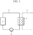
- the nuclear power plant includes a primary cooling circuit (circuit) 2 that circulates primary cooling helium, which acts as coolant containing radioactive nuclides, between a high-temperature reactor 1 and a heat exchanger 3, and a secondary cooling circuit 4 that circulates secondary cooling helium, which acts as a power generating fluid, between the heat exchanger 3 and a power generation facility (not shown).
- a primary cooling circuit circuit 2 that circulates primary cooling helium, which acts as coolant containing radioactive nuclides, between a high-temperature reactor 1 and a heat exchanger 3
- secondary cooling circuit 4 that circulates secondary cooling helium, which acts as a power generating fluid, between the heat exchanger 3 and a power generation facility (not shown).
- the primary cooling helium circulating through the primary cooling circuit 2 transmits high-temperature heat (about 950°C), which is generated by nuclear fission in nuclear fuel in the high-temperature reactor 1, to the heat exchanger 3.
- high-temperature heat about 950°C
- the heat of the primary cooling helium is transferred to the secondary cooling helium circulating through the secondary cooling circuit 4, and the heat transferred to the secondary cooling helium is transmitted to the power generation facility to generate power.
- a circulator (rotary device) 10 used in such a nuclear power plant accelerates the primary cooling helium in the primary cooling circuit 2 between the high-temperature reactor 1 and the heat exchanger 3 after heat is transferred to the secondary cooling helium, and then the circulator 10 returns the primary cooling helium to the high-temperature reactor 1.
- the circulator 10 includes a casing 11 having an inlet 11a and an outlet 11b, an impeller (rotor) 12 accommodated in the casing 11, and a motor 13.
- the impeller 12 is fixed to an output shaft 13a (rotor shaft) of the motor 13 and constitutes a rotary mechanism with the output shaft 13a.
- the impeller 12 rotates in response to the output of the motor 13, accelerates the primary cooling helium introduced into the casing 11 through the inlet 11a of the casing 11 from the heat exchanger 3, and discharges the helium to the high-temperature reactor 1 from the outlet 11b.
- At least the impeller 12 and the output shaft 13a of the rotary mechanism are composed of a low-effective diffusion coefficient alloy having a lower effective diffusion coefficient than a polycrystalline alloy (normally-grained crystalline material), that is, a coarsely-grained crystalline material with a larger grain size to have a lower effective diffusion coefficient prepared by reducing a cooling speed in solidification of molten metal or performing heat treatment.
- a polycrystalline alloy normally-grained crystalline material
- At least the impeller 12 and the output shaft 13a of the rotary mechanism may be made of a monocrystalline material having a lower effective diffusion coefficient prepared by solidifying molten metal from its one end in one direction.
- the radioactive nuclides of a fission product generated in the high-temperature reactor 1 and a radioactive corrosion product generated by corrosion of a core internal-structure material may be contained in the primary cooling helium and may be introduced into the casing 11 so as to be deposited in contact with the impeller 12 and the output shaft 13a of the rotary mechanism.
- the impeller 12 and the output shaft 13a of the rotary mechanism are made of a coarsely-grained crystalline material or a monocrystalline material having a lower effective diffusion coefficient than a polycrystalline alloy (normally-grained crystalline material), which can suppress deep diffusion of radioactive nuclides into the impeller 12 and the output shaft 13a of the rotary mechanism.
- the impeller 12 and the output shaft 13a of the rotary mechanism are hardly contaminated by radioactive nuclides, thereby reducing the amount of radioactive waste during the dismantlement of the facility.
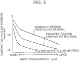
- radioactive nuclides in the use of a polycrystalline alloy (normally-grained crystalline material) for the impeller 12 and the output shaft 13a of the rotary mechanism of the circulator 10 was compared with the content of radioactive nuclides in the use of the coarsely-grained crystalline material described above.
- a polycrystalline alloy normally-grained crystalline material
- radioactive nuclides are deeply diffused from the surface of the impeller 12 or the output shaft 13a, whereas in the case of using a coarsely-grained crystalline material, radioactive nuclides are not deeply diffused.
- the circulator 10 can prevent radioactive nuclides from deeply diffusing into the impeller 12 and the output shaft 13a of the rotary mechanism.
- the impeller 12 and the output shaft 13a of the rotary mechanism are made of a coarsely-grained crystalline material or a monocrystalline material having a lower effective diffusion coefficient than that of a polycrystalline alloy (normally-grained crystalline material).
- the impeller 12 and the output shaft 13a of the rotary mechanism may be made of a lattice diffusion coefficient reducing material prepared by doping Ni with an element having a lower lattice diffusion coefficient than Ni.
- a coarsely-grained crystalline material containing a monocrystalline material having a lower effective diffusion coefficient may be combined with a lattice diffusion coefficient reducing material prepared by doping Ni with an element having a lower lattice diffusion coefficient than Ni.
- radioactive nuclides in the use of a polycrystalline alloy (normally-grained crystalline material) for the impeller 12 and the output shaft 13a of the rotary mechanism of the circulator 10 was compared with the content of radioactive nuclides in the use of the reduced lattice diffusion coefficient material according to the another embodiment.
- a polycrystalline alloy normally-grained crystalline material
- radioactive nuclides are deeply diffused from the surface of the impeller 12 or the output shaft 13a, whereas in the case of using a lattice diffusion coefficient reducing material, radioactive nuclides are not deeply diffused.
- the circulator 10 can prevent radioactive nuclides from deeply diffusing into the impeller 12 and the output shaft 13a of the rotary mechanism.
- the rotary device for the nuclear power facility according to the present invention is used as a circulator for a nuclear plant for explanation as an example.
- the present invention is not limited to this configuration and is also applicable to a centrifugal circulator (pump), an axial-flow circulator (pump), a steam turbine, a gas turbine, or a gas compressor in a nuclear fuel reprocessing facility or a nuclear fuel fabrication facility.
- a low-effective diffusion coefficient alloy having a lower effective diffusion coefficient than that of a polycrystalline alloy is used only for the impeller 12 and the output shaft 13a of the rotary mechanism.
- the present invention is not limited to this configuration.
- a low-effective diffusion coefficient alloy having a lower effective diffusion coefficient than that of a polycrystalline alloy is also applicable to the casing 11.
- the configuration of the rotary device for the nuclear power facility according to the present invention is not limited to the configuration of the embodiment described above.
- the rotor of the rotary mechanism may be a blade or the rotary mechanism may include a turbine disc, a bearing, or a sealing member.
- a first aspect of the present invention is a rotary device for a nuclear power facility, the rotary device being placed in a circuit for coolant containing radioactive nuclides in the nuclear power facility, the rotary device including a casing and a rotary mechanism provided with, in the casing, a rotor and a rotor shaft that come into contact with the coolant containing the radioactive nuclides passing through the casing.
- the casing and the rotary mechanism at least the rotor and the rotor shaft of the rotary mechanism are composed of a low-effective diffusion coefficient alloy having a lower effective diffusion coefficient than a polycrystalline alloy (normally-grained crystalline material).
- the low-effective diffusion coefficient alloy is a coarsely-grained crystalline material containing a monocrystalline material with a larger grain size to have a lower effective diffusion coefficient than the polycrystalline alloy.
- the low-effective diffusion coefficient alloy is a lattice diffusion coefficient reducing material prepared by doping Ni with an element having a lower lattice diffusion coefficient than Ni.
- the low-effective diffusion coefficient alloy is a combination of a coarsely-grained crystalline material containing a monocrystalline material with a larger grain size to have a lower effective diffusion coefficient than the polycrystalline alloy and a lattice diffusion coefficient reducing material prepared by doping Ni with an element having a lower lattice diffusion coefficient than Ni.
- the nuclear power facility includes a nuclear power plant having a nuclear reactor, a nuclear fuel reprocessing facility, and a fuel fabrication facility.
- the rotary device includes a centrifugal circulator (pump), an axial-flow circulator (pump), a steam turbine, a gas turbine, and a gas compressor.
- the coolant containing radioactive nuclides may be helium, water, or sodium.
- the radioactive nuclides of a fission product generated in the nuclear reactor and a radioactive corrosion product generated by corrosion of a core internal-structure material may be contained in the cooling fluid and may be introduced into the casing so as to be deposited in contact with the impeller and the rotor shaft of the rotary mechanism.
- the casing and the rotary mechanism at least the rotor and the rotor shaft of the rotary mechanism are made of a low-effective diffusion coefficient alloy having a lower effective diffusion coefficient than a polycrystalline alloy (normally-grained crystalline material), which can suppress the deep diffusion of radioactive nuclides into the rotor and the rotor shaft of the rotary mechanism.
- the casing and the rotary mechanism at least the rotor and the rotor shaft of the rotary mechanism are hardly contaminated by radioactive nuclides, thereby reducing the amount of radioactive waste during the dismantlement of the facility.
Landscapes
- Engineering & Computer Science (AREA)
- Physics & Mathematics (AREA)
- General Engineering & Computer Science (AREA)
- Plasma & Fusion (AREA)
- High Energy & Nuclear Physics (AREA)
- Mechanical Engineering (AREA)
- Chemical & Material Sciences (AREA)
- Manufacturing & Machinery (AREA)
- Materials Engineering (AREA)
- Metallurgy (AREA)
- Organic Chemistry (AREA)
- Structures Of Non-Positive Displacement Pumps (AREA)
Abstract
Description
- The present invention relates to a rotary device for a nuclear power facility, the rotary device being placed in a circuit of coolant containing radioactive nuclides in the nuclear power facility.
- A conventional nuclear power plant such as the nuclear power facility described above is disclosed in, for example,
Patent Document 1. - The nuclear power plant includes a primary cooling circuit that circulates primary cooling helium, which acts as coolant containing radioactive nuclides, between a high-temperature reactor and a heat exchanger, and a secondary cooling circuit that circulates secondary cooling helium, which acts as a power generating fluid, between the heat exchanger and a power generation facility.
- In this nuclear power plant, heat generated in the high-temperature reactor is transmitted to the heat exchanger by the primary cooling helium that circulates through the primary cooling circuit. In the heat exchanger, the heat of the primary cooling helium is transferred to the secondary cooling helium that circulates through the secondary cooling circuit, and the heat transferred to the secondary cooling helium is transmitted to the power generation facility to generate power.
- In such a nuclear power plant, a circulator (rotary device) is typically disposed in the primary cooling circuit so as to circulate the primary cooling helium with higher speeds.
- Patent Document 1: Japanese Patent Laid-Open No.
10-319169 - In the circulator of the nuclear power plant described above, a polycrystalline alloy (normally-grained crystalline material) is used for a rotor or a rotor shaft in contact with the primary cooling helium containing radioactive nuclides. Thus, during operations repeated to circulate the primary cooling helium between the high-temperature reactor and the heat exchanger, the radioactive nuclides contained in the primary cooling helium, for example, silver may deeply diffuse into the polycrystalline alloy constituting the rotor or the rotor shaft.
- Specifically, in the circulator of the conventional nuclear power plant, in order to prevent an operator from being exposed to, for example, gamma rays from silver having deeply diffused into the polycrystalline alloy, it is necessary to limit an operating time or use a remote device during maintenance. This may disadvantageously cause high maintenance cost, which has been a conventional problem to be solved.
- The present invention has been made in consideration of the conventional problem. An object of the present invention is to provide a rotary device for a nuclear power facility that can prevent radioactive nuclides from deeply diffusing into a material constituting a rotor or a rotor shaft in contact with coolant containing the radioactive nuclides, thereby reducing the cost of maintenance.
- As shown in
FIG. 5 , the diffusion of the radioactive nuclides into a material is a phenomenon in which the atoms of a material are replaced with the atoms of the radioactive nuclides, for example, the atoms of silver (Ag) by heat. It is known that the speed of diffusion from a surface S of the material to a grain boundary Ca, which is a border of a crystal grain C, is higher than that at the center of the crystal grain C. - In view of this phenomenon, the inventors found that the number of crystal grains (grain boundaries) in a unit volume can be reduced by increasing the grain diameters of crystal grains or single crystallization, that is, an Ag content increased by diffusion per unit volume can be reduced by narrowing the areas of grain boundaries having high diffusion speeds.
- Moreover, the inventors have also focused on a lattice diffusion coefficient and found that the amount of diffusion can be also reduced by adding (doping) a large amount of an element having a smaller lattice diffusion coefficient than that of Ni to an ordinary Ni-base alloy so as to reduce the lattice diffusion coefficient (change an alloy composition). Thus, the present invention is achieved.
- In this case, diffusion coefficients including both of a grain boundary diffusion coefficient and a lattice diffusion coefficient are denoted as "effective diffusion coefficient."
- The present invention is a rotary device for a nuclear power facility, the rotary device being placed in a circuit for coolant containing radioactive nuclides in the nuclear power facility, the rotary device including: a casing; and a rotary mechanism provided with, in the casing, a rotor and a rotor shaft that come into contact with the coolant containing the radioactive nuclides passing through the casing. Regarding the casing and the rotary mechanism, at least the rotor and the rotor shaft of the rotary mechanism are composed of a low-effective diffusion coefficient alloy having a lower effective diffusion coefficient than a polycrystalline alloy (normally-grained crystalline material).
- In the rotary device for the nuclear power facility according to the present invention, for example, the radioactive nuclides of a fission product generated in a nuclear reactor and a radioactive corrosion product generated by corrosion of a core internal-structure material may be contained in the coolant and may be introduced into the casing so as to be deposited in contact with the rotor and the rotor shaft of the rotary mechanism. Even in this case, regarding the casing and the rotary mechanism, at least the rotor and the rotor shaft of the rotary mechanism are composed of a low-effective diffusion coefficient alloy having a lower effective diffusion coefficient than a polycrystalline alloy (normally-grained crystalline material), which can suppress the diffusion of radioactive nuclides deeply into the rotor and the rotor shaft of the rotary mechanism.
- Additionally, regarding the casing and the rotary mechanism, at least the rotor and the rotor shaft of the rotary mechanism are hardly contaminated by radioactive nuclides, thereby reducing the amount of radioactive waste during the dismantlement of the facility.
- The present invention can achieve quite an excellent effect of preventing radioactive nuclides from deeply diffusing into a material constituting at least a rotor or a rotor shaft, thereby reducing the cost of maintenance.
-
-
FIG. 1 is a schematic diagram showing a cooling circuit for a nuclear power plant including a rotary device for a nuclear power facility according to an embodiment of the present invention. -
FIG. 2 is a side explanatory drawing showing a cross section of a rotary mechanism part of the rotary device shown inFIG. 1 . -
FIG. 3 is a graph showing the effect of the rotary device for the nuclear power facility according to the embodiment. -
FIG. 4 is a graph showing the effect of a rotary device for a nuclear power facility according to another embodiment. -
FIG. 5 is a schematic diagram showing crystal grains and crystal boundaries near the surface of a polycrystalline alloy. - The present invention will be described below with reference to the accompanying drawings.
-
FIGS. 1 and2 show an embodiment of a rotary device for a nuclear power facility according to the present invention. In this embodiment, the rotary device for the nuclear power facility according to the present invention is used as a circulator for a nuclear power plant for explanation as an example. - As shown in
FIG. 1 , the nuclear power plant includes a primary cooling circuit (circuit) 2 that circulates primary cooling helium, which acts as coolant containing radioactive nuclides, between a high-temperature reactor 1 and aheat exchanger 3, and asecondary cooling circuit 4 that circulates secondary cooling helium, which acts as a power generating fluid, between theheat exchanger 3 and a power generation facility (not shown). - In this nuclear power plant, the primary cooling helium circulating through the
primary cooling circuit 2 transmits high-temperature heat (about 950°C), which is generated by nuclear fission in nuclear fuel in the high-temperature reactor 1, to theheat exchanger 3. In theheat exchanger 3, the heat of the primary cooling helium is transferred to the secondary cooling helium circulating through thesecondary cooling circuit 4, and the heat transferred to the secondary cooling helium is transmitted to the power generation facility to generate power. - A circulator (rotary device) 10 used in such a nuclear power plant accelerates the primary cooling helium in the
primary cooling circuit 2 between the high-temperature reactor 1 and theheat exchanger 3 after heat is transferred to the secondary cooling helium, and then thecirculator 10 returns the primary cooling helium to the high-temperature reactor 1. As shown inFIG. 2 , thecirculator 10 includes acasing 11 having aninlet 11a and anoutlet 11b, an impeller (rotor) 12 accommodated in thecasing 11, and amotor 13. - The
impeller 12 is fixed to anoutput shaft 13a (rotor shaft) of themotor 13 and constitutes a rotary mechanism with theoutput shaft 13a. Theimpeller 12 rotates in response to the output of themotor 13, accelerates the primary cooling helium introduced into thecasing 11 through theinlet 11a of thecasing 11 from theheat exchanger 3, and discharges the helium to the high-temperature reactor 1 from theoutlet 11b. - In this case, regarding the
casing 11 and the rotary mechanism of thecirculator 10, at least theimpeller 12 and theoutput shaft 13a of the rotary mechanism are composed of a low-effective diffusion coefficient alloy having a lower effective diffusion coefficient than a polycrystalline alloy (normally-grained crystalline material), that is, a coarsely-grained crystalline material with a larger grain size to have a lower effective diffusion coefficient prepared by reducing a cooling speed in solidification of molten metal or performing heat treatment. - In this case, regarding the
casing 11 and the rotary mechanism of thecirculator 10, at least theimpeller 12 and theoutput shaft 13a of the rotary mechanism may be made of a monocrystalline material having a lower effective diffusion coefficient prepared by solidifying molten metal from its one end in one direction. - In the
circulator 10 according to the present embodiment, the radioactive nuclides of a fission product generated in the high-temperature reactor 1 and a radioactive corrosion product generated by corrosion of a core internal-structure material may be contained in the primary cooling helium and may be introduced into thecasing 11 so as to be deposited in contact with theimpeller 12 and theoutput shaft 13a of the rotary mechanism. Even in this case, theimpeller 12 and theoutput shaft 13a of the rotary mechanism are made of a coarsely-grained crystalline material or a monocrystalline material having a lower effective diffusion coefficient than a polycrystalline alloy (normally-grained crystalline material), which can suppress deep diffusion of radioactive nuclides into theimpeller 12 and theoutput shaft 13a of the rotary mechanism. - This can reduce the cost of maintenance. Additionally, the
impeller 12 and theoutput shaft 13a of the rotary mechanism are hardly contaminated by radioactive nuclides, thereby reducing the amount of radioactive waste during the dismantlement of the facility. - The content of radioactive nuclides in the use of a polycrystalline alloy (normally-grained crystalline material) for the
impeller 12 and theoutput shaft 13a of the rotary mechanism of thecirculator 10 was compared with the content of radioactive nuclides in the use of the coarsely-grained crystalline material described above. As shown in the graph ofFIG. 3 , in the case of using a polycrystalline alloy (normally-grained crystalline material), radioactive nuclides are deeply diffused from the surface of theimpeller 12 or theoutput shaft 13a, whereas in the case of using a coarsely-grained crystalline material, radioactive nuclides are not deeply diffused. - In the case of using a monocrystalline material with an effective diffusion coefficient reduced to one hundredth of that of a polycrystalline alloy (normally-grained crystalline material), in particular, it is found that the content of radioactive nuclides in a deep portion is reduced to one tenth.
- This proved that the
circulator 10 according to this embodiment can prevent radioactive nuclides from deeply diffusing into theimpeller 12 and theoutput shaft 13a of the rotary mechanism. - In the embodiment described above, the
impeller 12 and theoutput shaft 13a of the rotary mechanism are made of a coarsely-grained crystalline material or a monocrystalline material having a lower effective diffusion coefficient than that of a polycrystalline alloy (normally-grained crystalline material). According to another embodiment, theimpeller 12 and theoutput shaft 13a of the rotary mechanism may be made of a lattice diffusion coefficient reducing material prepared by doping Ni with an element having a lower lattice diffusion coefficient than Ni. According to still another embodiment, a coarsely-grained crystalline material containing a monocrystalline material having a lower effective diffusion coefficient may be combined with a lattice diffusion coefficient reducing material prepared by doping Ni with an element having a lower lattice diffusion coefficient than Ni. - The content of radioactive nuclides in the use of a polycrystalline alloy (normally-grained crystalline material) for the
impeller 12 and theoutput shaft 13a of the rotary mechanism of thecirculator 10 was compared with the content of radioactive nuclides in the use of the reduced lattice diffusion coefficient material according to the another embodiment. As shown in the graph ofFIG. 4 , in the case of using a polycrystalline alloy (normally-grained crystalline material), radioactive nuclides are deeply diffused from the surface of theimpeller 12 or theoutput shaft 13a, whereas in the case of using a lattice diffusion coefficient reducing material, radioactive nuclides are not deeply diffused. - This proved that the
circulator 10 according to this embodiment can prevent radioactive nuclides from deeply diffusing into theimpeller 12 and theoutput shaft 13a of the rotary mechanism. - In the embodiment described above, the rotary device for the nuclear power facility according to the present invention is used as a circulator for a nuclear plant for explanation as an example. The present invention is not limited to this configuration and is also applicable to a centrifugal circulator (pump), an axial-flow circulator (pump), a steam turbine, a gas turbine, or a gas compressor in a nuclear fuel reprocessing facility or a nuclear fuel fabrication facility.
- In the embodiment described above, a low-effective diffusion coefficient alloy having a lower effective diffusion coefficient than that of a polycrystalline alloy is used only for the
impeller 12 and theoutput shaft 13a of the rotary mechanism. The present invention is not limited to this configuration. In another configuration, a low-effective diffusion coefficient alloy having a lower effective diffusion coefficient than that of a polycrystalline alloy is also applicable to thecasing 11. - The configuration of the rotary device for the nuclear power facility according to the present invention is not limited to the configuration of the embodiment described above. For example, the rotor of the rotary mechanism may be a blade or the rotary mechanism may include a turbine disc, a bearing, or a sealing member.
- A first aspect of the present invention is a rotary device for a nuclear power facility, the rotary device being placed in a circuit for coolant containing radioactive nuclides in the nuclear power facility, the rotary device including a casing and a rotary mechanism provided with, in the casing, a rotor and a rotor shaft that come into contact with the coolant containing the radioactive nuclides passing through the casing. Regarding the casing and the rotary mechanism, at least the rotor and the rotor shaft of the rotary mechanism are composed of a low-effective diffusion coefficient alloy having a lower effective diffusion coefficient than a polycrystalline alloy (normally-grained crystalline material).
- According to a second aspect of the present invention, the low-effective diffusion coefficient alloy is a coarsely-grained crystalline material containing a monocrystalline material with a larger grain size to have a lower effective diffusion coefficient than the polycrystalline alloy.
- According to a third aspect of the present invention, the low-effective diffusion coefficient alloy is a lattice diffusion coefficient reducing material prepared by doping Ni with an element having a lower lattice diffusion coefficient than Ni.
- According to a fourth embodiment of the present invention, the low-effective diffusion coefficient alloy is a combination of a coarsely-grained crystalline material containing a monocrystalline material with a larger grain size to have a lower effective diffusion coefficient than the polycrystalline alloy and a lattice diffusion coefficient reducing material prepared by doping Ni with an element having a lower lattice diffusion coefficient than Ni.
- In the rotary device for the nuclear power facility according to the present invention, the nuclear power facility includes a nuclear power plant having a nuclear reactor, a nuclear fuel reprocessing facility, and a fuel fabrication facility.
- In the rotary device for the nuclear power facility according to the present invention, the rotary device includes a centrifugal circulator (pump), an axial-flow circulator (pump), a steam turbine, a gas turbine, and a gas compressor.
- In the rotary device for the nuclear power facility according to the present invention, the coolant containing radioactive nuclides may be helium, water, or sodium.
- In the rotary device for the nuclear power facility according to the present invention, the radioactive nuclides of a fission product generated in the nuclear reactor and a radioactive corrosion product generated by corrosion of a core internal-structure material may be contained in the cooling fluid and may be introduced into the casing so as to be deposited in contact with the impeller and the rotor shaft of the rotary mechanism. Even in this case, regarding the casing and the rotary mechanism, at least the rotor and the rotor shaft of the rotary mechanism are made of a low-effective diffusion coefficient alloy having a lower effective diffusion coefficient than a polycrystalline alloy (normally-grained crystalline material), which can suppress the deep diffusion of radioactive nuclides into the rotor and the rotor shaft of the rotary mechanism.
- Additionally, regarding the casing and the rotary mechanism, at least the rotor and the rotor shaft of the rotary mechanism are hardly contaminated by radioactive nuclides, thereby reducing the amount of radioactive waste during the dismantlement of the facility.
-
- 1
- high-temperature gas-cooled reactor
- 2
- primary cooling circuit (circuit)
- 10
- circulator (rotary device)
- 11
- casing
- 12
- impeller (rotor)
- 13
- motor
- 13a
- output shaft (rotor shaft)
Claims (4)
- A rotary device for a nuclear power facility, the rotary device being placed in a circuit for coolant containing radioactive nuclides in the nuclear power facility,
the rotary device comprising:a casing; anda rotary mechanism provided with, in the casing, a rotor and a rotor shaft that come into contact with the coolant containing the radioactive nuclides passing through the casing,wherein regarding the casing and the rotary mechanism, at least the rotor and the rotor shaft of the rotary mechanism are composed of a low-effective diffusion coefficient alloy having a lower effective diffusion coefficient than a polycrystalline alloy. - The rotary device for a nuclear power facility according to claim 1, wherein the low-effective diffusion coefficient alloy is a coarsely-grained crystalline material containing a monocrystalline material with a larger grain size to have a lower effective diffusion coefficient than the polycrystalline alloy.
- The rotary device for a nuclear power facility according to claim 1, wherein the low-effective diffusion coefficient alloy is a lattice diffusion coefficient reducing material prepared by doping Ni with an element having a lower lattice diffusion coefficient than Ni.
- The rotary device for a nuclear power facility according to claim 1, wherein the low-effective diffusion coefficient alloy is a combination of a coarsely-grained crystalline material containing a monocrystalline material with a larger grain size to have a lower effective diffusion coefficient than the polycrystalline alloy and a lattice diffusion coefficient reducing material prepared by doping Ni with an element having a lower lattice diffusion coefficient than Ni.
Priority Applications (1)
| Application Number | Priority Date | Filing Date | Title |
|---|---|---|---|
| EP19153976.6A EP3496110A1 (en) | 2014-05-21 | 2015-05-12 | Rotary device for nuclear power facility |
Applications Claiming Priority (2)
| Application Number | Priority Date | Filing Date | Title |
|---|---|---|---|
| JP2014105242A JP6528926B2 (en) | 2014-05-21 | 2014-05-21 | Rotating equipment of nuclear facilities |
| PCT/JP2015/063554 WO2015178240A1 (en) | 2014-05-21 | 2015-05-12 | Rotary device for nuclear power facility |
Related Child Applications (2)
| Application Number | Title | Priority Date | Filing Date |
|---|---|---|---|
| EP19153976.6A Division-Into EP3496110A1 (en) | 2014-05-21 | 2015-05-12 | Rotary device for nuclear power facility |
| EP19153976.6A Division EP3496110A1 (en) | 2014-05-21 | 2015-05-12 | Rotary device for nuclear power facility |
Publications (3)
| Publication Number | Publication Date |
|---|---|
| EP3147911A1 true EP3147911A1 (en) | 2017-03-29 |
| EP3147911A4 EP3147911A4 (en) | 2017-12-27 |
| EP3147911B1 EP3147911B1 (en) | 2019-08-21 |
Family
ID=54553913
Family Applications (2)
| Application Number | Title | Priority Date | Filing Date |
|---|---|---|---|
| EP15796101.2A Active EP3147911B1 (en) | 2014-05-21 | 2015-05-12 | Rotary device for nuclear power facility |
| EP19153976.6A Pending EP3496110A1 (en) | 2014-05-21 | 2015-05-12 | Rotary device for nuclear power facility |
Family Applications After (1)
| Application Number | Title | Priority Date | Filing Date |
|---|---|---|---|
| EP19153976.6A Pending EP3496110A1 (en) | 2014-05-21 | 2015-05-12 | Rotary device for nuclear power facility |
Country Status (6)
| Country | Link |
|---|---|
| US (1) | US10699817B2 (en) |
| EP (2) | EP3147911B1 (en) |
| JP (1) | JP6528926B2 (en) |
| KR (3) | KR20170003690A (en) |
| CN (1) | CN106256006A (en) |
| WO (1) | WO2015178240A1 (en) |
Family Cites Families (27)
| Publication number | Priority date | Publication date | Assignee | Title |
|---|---|---|---|---|
| JP3402603B2 (en) | 1986-03-27 | 2003-05-06 | ゼネラル・エレクトリック・カンパニイ | Nickel-base-superalloy with improved low angle grain boundary resistance for producing single crystal products |
| GB2234521B (en) | 1986-03-27 | 1991-05-01 | Gen Electric | Nickel-base superalloys for producing single crystal articles having improved tolerance to low angle grain boundaries |
| JPH01124796A (en) * | 1987-01-29 | 1989-05-17 | Proto Power Corp | Gas circulator for nuclear reaction furnace, use thereof, nuclear reaction furnace system and operation thereof |
| JP2585900B2 (en) * | 1991-08-28 | 1997-02-26 | 株式会社日立製作所 | Manufacturing method of heat-resistant reinforcing member |
| JPH0626495A (en) * | 1992-07-09 | 1994-02-01 | Toshiba Corp | Manufacture of hydraulic pump |
| JPH10319169A (en) | 1997-05-21 | 1998-12-04 | Japan Atom Energy Res Inst | Helium-cooled fast breeder reactor |
| JPH1180905A (en) * | 1997-09-10 | 1999-03-26 | Hitachi Ltd | Austenitic stainless steel with excellent corrosion resistance and its use |
| JP4458579B2 (en) * | 1999-07-19 | 2010-04-28 | 株式会社東芝 | Reactor material and manufacturing method thereof |
| JP3910588B2 (en) * | 2001-10-31 | 2007-04-25 | 独立行政法人科学技術振興機構 | ReCr alloy coating for diffusion barrier |
| JP4184695B2 (en) * | 2002-04-09 | 2008-11-19 | 株式会社東芝 | Water supply pump |
| JP4496361B2 (en) | 2003-05-30 | 2010-07-07 | 独立行政法人 日本原子力研究開発機構 | Method for forming coating layer of heat-resistant ceramic thin film on Ni-base heat-resistant alloy |
| JP2005283411A (en) * | 2004-03-30 | 2005-10-13 | Toshiba Corp | Internal pump |
| JP4304499B2 (en) * | 2004-10-13 | 2009-07-29 | 住友金属工業株式会社 | Method for producing Ni-base alloy material for nuclear power plant |
| JP4518984B2 (en) * | 2005-03-11 | 2010-08-04 | 中国電力株式会社 | Hydrogen injection method for nuclear power plant |
| CN1988357A (en) * | 2005-12-22 | 2007-06-27 | 朱晓良 | High energy physics nuclear-magnetic power |
| US9322089B2 (en) * | 2006-06-02 | 2016-04-26 | Alstom Technology Ltd | Nickel-base alloy for gas turbine applications |
| EP2110449A4 (en) * | 2006-09-13 | 2011-04-27 | Nat Inst For Materials Science | HEAT-RESISTANT ELEMENT |
| JP5217576B2 (en) * | 2008-04-02 | 2013-06-19 | 大同特殊鋼株式会社 | Austenitic stainless steel for heat-resistant parts and heat-resistant parts using the same |
| CN101800464B (en) * | 2010-01-28 | 2011-11-09 | 清华大学 | Sealing and driving device in high-temperature gas-cooled reactor helium gas space and driving device thereof |
| CH703386A1 (en) * | 2010-06-30 | 2011-12-30 | Alstom Technology Ltd | A process for the preparation of a composed of a nickel-base superalloy monocrystalline component. |
| RU2441089C1 (en) * | 2010-12-30 | 2012-01-27 | Юрий Васильевич Кузнецов | ANTIRUST ALLOY BASED ON Fe-Cr-Ni, ARTICLE THEREFROM AND METHOD OF PRODUCING SAID ARTICLE |
| CN103090985B (en) * | 2011-10-31 | 2015-03-04 | 清华大学 | Sheathed thermocouple component penetrating high-temperature high-pressure helium pressure shell |
| JP5356572B2 (en) * | 2012-04-24 | 2013-12-04 | 株式会社日立製作所 | Turbine rotor |
| DE102012015586A1 (en) * | 2012-08-08 | 2014-05-15 | MTU Aero Engines AG | Duplex phase CrAl coating for improved corrosion / oxidation protection |
| US8826639B2 (en) | 2012-08-22 | 2014-09-09 | Hi Eff Rescue LLC | High efficiency power generation system and system upgrades |
| US9551049B2 (en) | 2012-08-28 | 2017-01-24 | United Technologies Corporation | High elastic modulus shafts and method of manufacture |
| BR112016004477B1 (en) * | 2013-11-26 | 2022-03-03 | Joint Stock Company Akme Engineering | NUCLEAR FUEL TABLET WITH ENRICHED THERMAL CONDUCTIVITY AND ITS PREPARATION METHOD |
-
2014
- 2014-05-21 JP JP2014105242A patent/JP6528926B2/en active Active
-
2015
- 2015-05-12 KR KR1020167035044A patent/KR20170003690A/en not_active Ceased
- 2015-05-12 KR KR1020197004272A patent/KR102070668B1/en active Active
- 2015-05-12 CN CN201580023931.6A patent/CN106256006A/en active Pending
- 2015-05-12 EP EP15796101.2A patent/EP3147911B1/en active Active
- 2015-05-12 KR KR1020197004269A patent/KR102070669B1/en active Active
- 2015-05-12 WO PCT/JP2015/063554 patent/WO2015178240A1/en not_active Ceased
- 2015-05-12 EP EP19153976.6A patent/EP3496110A1/en active Pending
-
2016
- 2016-11-17 US US15/354,445 patent/US10699817B2/en active Active
Also Published As
| Publication number | Publication date |
|---|---|
| JP2015219211A (en) | 2015-12-07 |
| US10699817B2 (en) | 2020-06-30 |
| KR102070669B1 (en) | 2020-01-29 |
| WO2015178240A1 (en) | 2015-11-26 |
| KR102070668B1 (en) | 2020-01-29 |
| KR20190018051A (en) | 2019-02-20 |
| EP3147911A4 (en) | 2017-12-27 |
| EP3147911B1 (en) | 2019-08-21 |
| JP6528926B2 (en) | 2019-06-12 |
| EP3496110A1 (en) | 2019-06-12 |
| KR20170003690A (en) | 2017-01-09 |
| KR20190018050A (en) | 2019-02-20 |
| CN106256006A (en) | 2016-12-21 |
| US20170148534A1 (en) | 2017-05-25 |
Similar Documents
| Publication | Publication Date | Title |
|---|---|---|
| Loewen et al. | Status of research and development of the lead-alloy-cooled fast reactor | |
| WO2020123513A2 (en) | Salt wall in a molten salt reactor | |
| WO2021133952A3 (en) | Low power, fast spectrum molten fuel reactor | |
| CA2955978C (en) | Doppler reactivity augmentation device | |
| JOP20190299A1 (en) | Reactor core | |
| EP3147911B1 (en) | Rotary device for nuclear power facility | |
| JP6734574B2 (en) | Rotating equipment for nuclear facilities | |
| JP7136449B2 (en) | Plutonium extinction molten salt reactor, power generation system using the same, and operation method of plutonium extinction molten salt reactor | |
| RU143978U1 (en) | THERMONUCLEAR REACTOR FORM | |
| CN105679384A (en) | Small nuclear power plant | |
| RU2543573C1 (en) | Intracircuit passivation method of steel surfaces of fast neutron nuclear reactor | |
| MY184123A (en) | Nuclear power plant and device for feeding a cover gas into the plant | |
| Brumfiel | Fukushima reaches cold shutdown | |
| Fedorovich et al. | Perspective Fuel Rod with Alloyed Lead in Contact Layer for Reactor BREST-OD-300 | |
| Chen et al. | The Study of TRR Radial Thermal Shielding Dismantling Process-20063 | |
| EP3783623B1 (en) | Method for decommissioning nuclear facilities | |
| RU115956U1 (en) | NUCLEAR POWER PLANT | |
| Susanto et al. | Study of identification of safety provisions in power reactor terrace design | |
| Nikulin et al. | Calculated safety justification of the VVER-1000 reactor facility in the mode with the shutdown of one of the four MCPs during the operation at nominal power | |
| Chikazawa et al. | ICONE11-36599 Conceptual Design of a Small Lead-bismuth Cooled Reactor | |
| Zhang et al. | Development of transient thermal-hydraulic analysis code for the space thermionic reactor | |
| Vukovic et al. | Reactor Coolant Pump Motor Maintenance Experience in Krsko NPP | |
| Duan et al. | Study on the radiation field effect produced by primary loop zinc addition in PWR | |
| Choi et al. | Abnormal Behavior of Motor Surface Temperature of Canned Pump along Increasing Fluid Temperature | |
| Khrennikov | Russian Regulatory Body Approach to SFR Safety Design Criteria |
Legal Events
| Date | Code | Title | Description |
|---|---|---|---|
| STAA | Information on the status of an ep patent application or granted ep patent |
Free format text: STATUS: THE INTERNATIONAL PUBLICATION HAS BEEN MADE |
|
| PUAI | Public reference made under article 153(3) epc to a published international application that has entered the european phase |
Free format text: ORIGINAL CODE: 0009012 |
|
| STAA | Information on the status of an ep patent application or granted ep patent |
Free format text: STATUS: REQUEST FOR EXAMINATION WAS MADE |
|
| 17P | Request for examination filed |
Effective date: 20161111 |
|
| AK | Designated contracting states |
Kind code of ref document: A1 Designated state(s): AL AT BE BG CH CY CZ DE DK EE ES FI FR GB GR HR HU IE IS IT LI LT LU LV MC MK MT NL NO PL PT RO RS SE SI SK SM TR |
|
| AX | Request for extension of the european patent |
Extension state: BA ME |
|
| DAV | Request for validation of the european patent (deleted) | ||
| DAX | Request for extension of the european patent (deleted) | ||
| A4 | Supplementary search report drawn up and despatched |
Effective date: 20171127 |
|
| RIC1 | Information provided on ipc code assigned before grant |
Ipc: G21D 1/02 20060101ALI20171121BHEP Ipc: C21D 8/02 20060101ALI20171121BHEP Ipc: G21C 17/022 20060101ALI20171121BHEP Ipc: G21C 15/24 20060101ALI20171121BHEP Ipc: G21C 21/00 20060101ALI20171121BHEP Ipc: F04D 29/02 20060101ALI20171121BHEP Ipc: G21D 1/00 20060101AFI20171121BHEP |
|
| STAA | Information on the status of an ep patent application or granted ep patent |
Free format text: STATUS: EXAMINATION IS IN PROGRESS |
|
| 17Q | First examination report despatched |
Effective date: 20180927 |
|
| GRAP | Despatch of communication of intention to grant a patent |
Free format text: ORIGINAL CODE: EPIDOSNIGR1 |
|
| STAA | Information on the status of an ep patent application or granted ep patent |
Free format text: STATUS: GRANT OF PATENT IS INTENDED |
|
| RIC1 | Information provided on ipc code assigned before grant |
Ipc: F04D 7/08 20060101ALI20190221BHEP Ipc: G21C 17/022 20060101ALI20190221BHEP Ipc: G21C 21/00 20060101ALI20190221BHEP Ipc: G21D 1/00 20060101AFI20190221BHEP Ipc: G21D 1/02 20060101ALI20190221BHEP Ipc: G21C 15/24 20060101ALI20190221BHEP Ipc: F04D 29/02 20060101ALI20190221BHEP Ipc: C21D 8/02 20060101ALI20190221BHEP |
|
| INTG | Intention to grant announced |
Effective date: 20190319 |
|
| GRAS | Grant fee paid |
Free format text: ORIGINAL CODE: EPIDOSNIGR3 |
|
| GRAA | (expected) grant |
Free format text: ORIGINAL CODE: 0009210 |
|
| STAA | Information on the status of an ep patent application or granted ep patent |
Free format text: STATUS: THE PATENT HAS BEEN GRANTED |
|
| AK | Designated contracting states |
Kind code of ref document: B1 Designated state(s): AL AT BE BG CH CY CZ DE DK EE ES FI FR GB GR HR HU IE IS IT LI LT LU LV MC MK MT NL NO PL PT RO RS SE SI SK SM TR |
|
| REG | Reference to a national code |
Ref country code: GB Ref legal event code: FG4D |
|
| REG | Reference to a national code |
Ref country code: CH Ref legal event code: EP |
|
| REG | Reference to a national code |
Ref country code: DE Ref legal event code: R096 Ref document number: 602015036367 Country of ref document: DE |
|
| REG | Reference to a national code |
Ref country code: AT Ref legal event code: REF Ref document number: 1170677 Country of ref document: AT Kind code of ref document: T Effective date: 20190915 |
|
| REG | Reference to a national code |
Ref country code: IE Ref legal event code: FG4D |
|
| REG | Reference to a national code |
Ref country code: LT Ref legal event code: MG4D |
|
| REG | Reference to a national code |
Ref country code: NL Ref legal event code: MP Effective date: 20190821 |
|
| PG25 | Lapsed in a contracting state [announced via postgrant information from national office to epo] |
Ref country code: NO Free format text: LAPSE BECAUSE OF FAILURE TO SUBMIT A TRANSLATION OF THE DESCRIPTION OR TO PAY THE FEE WITHIN THE PRESCRIBED TIME-LIMIT Effective date: 20191121 Ref country code: LT Free format text: LAPSE BECAUSE OF FAILURE TO SUBMIT A TRANSLATION OF THE DESCRIPTION OR TO PAY THE FEE WITHIN THE PRESCRIBED TIME-LIMIT Effective date: 20190821 Ref country code: FI Free format text: LAPSE BECAUSE OF FAILURE TO SUBMIT A TRANSLATION OF THE DESCRIPTION OR TO PAY THE FEE WITHIN THE PRESCRIBED TIME-LIMIT Effective date: 20190821 Ref country code: SE Free format text: LAPSE BECAUSE OF FAILURE TO SUBMIT A TRANSLATION OF THE DESCRIPTION OR TO PAY THE FEE WITHIN THE PRESCRIBED TIME-LIMIT Effective date: 20190821 Ref country code: NL Free format text: LAPSE BECAUSE OF FAILURE TO SUBMIT A TRANSLATION OF THE DESCRIPTION OR TO PAY THE FEE WITHIN THE PRESCRIBED TIME-LIMIT Effective date: 20190821 Ref country code: BG Free format text: LAPSE BECAUSE OF FAILURE TO SUBMIT A TRANSLATION OF THE DESCRIPTION OR TO PAY THE FEE WITHIN THE PRESCRIBED TIME-LIMIT Effective date: 20191121 Ref country code: HR Free format text: LAPSE BECAUSE OF FAILURE TO SUBMIT A TRANSLATION OF THE DESCRIPTION OR TO PAY THE FEE WITHIN THE PRESCRIBED TIME-LIMIT Effective date: 20190821 Ref country code: PT Free format text: LAPSE BECAUSE OF FAILURE TO SUBMIT A TRANSLATION OF THE DESCRIPTION OR TO PAY THE FEE WITHIN THE PRESCRIBED TIME-LIMIT Effective date: 20191223 |
|
| PG25 | Lapsed in a contracting state [announced via postgrant information from national office to epo] |
Ref country code: GR Free format text: LAPSE BECAUSE OF FAILURE TO SUBMIT A TRANSLATION OF THE DESCRIPTION OR TO PAY THE FEE WITHIN THE PRESCRIBED TIME-LIMIT Effective date: 20191122 Ref country code: LV Free format text: LAPSE BECAUSE OF FAILURE TO SUBMIT A TRANSLATION OF THE DESCRIPTION OR TO PAY THE FEE WITHIN THE PRESCRIBED TIME-LIMIT Effective date: 20190821 Ref country code: AL Free format text: LAPSE BECAUSE OF FAILURE TO SUBMIT A TRANSLATION OF THE DESCRIPTION OR TO PAY THE FEE WITHIN THE PRESCRIBED TIME-LIMIT Effective date: 20190821 Ref country code: RS Free format text: LAPSE BECAUSE OF FAILURE TO SUBMIT A TRANSLATION OF THE DESCRIPTION OR TO PAY THE FEE WITHIN THE PRESCRIBED TIME-LIMIT Effective date: 20190821 Ref country code: IS Free format text: LAPSE BECAUSE OF FAILURE TO SUBMIT A TRANSLATION OF THE DESCRIPTION OR TO PAY THE FEE WITHIN THE PRESCRIBED TIME-LIMIT Effective date: 20191221 Ref country code: ES Free format text: LAPSE BECAUSE OF FAILURE TO SUBMIT A TRANSLATION OF THE DESCRIPTION OR TO PAY THE FEE WITHIN THE PRESCRIBED TIME-LIMIT Effective date: 20190821 |
|
| REG | Reference to a national code |
Ref country code: AT Ref legal event code: MK05 Ref document number: 1170677 Country of ref document: AT Kind code of ref document: T Effective date: 20190821 |
|
| PG25 | Lapsed in a contracting state [announced via postgrant information from national office to epo] |
Ref country code: TR Free format text: LAPSE BECAUSE OF FAILURE TO SUBMIT A TRANSLATION OF THE DESCRIPTION OR TO PAY THE FEE WITHIN THE PRESCRIBED TIME-LIMIT Effective date: 20190821 |
|
| PG25 | Lapsed in a contracting state [announced via postgrant information from national office to epo] |
Ref country code: IT Free format text: LAPSE BECAUSE OF FAILURE TO SUBMIT A TRANSLATION OF THE DESCRIPTION OR TO PAY THE FEE WITHIN THE PRESCRIBED TIME-LIMIT Effective date: 20190821 Ref country code: AT Free format text: LAPSE BECAUSE OF FAILURE TO SUBMIT A TRANSLATION OF THE DESCRIPTION OR TO PAY THE FEE WITHIN THE PRESCRIBED TIME-LIMIT Effective date: 20190821 Ref country code: PL Free format text: LAPSE BECAUSE OF FAILURE TO SUBMIT A TRANSLATION OF THE DESCRIPTION OR TO PAY THE FEE WITHIN THE PRESCRIBED TIME-LIMIT Effective date: 20190821 Ref country code: DK Free format text: LAPSE BECAUSE OF FAILURE TO SUBMIT A TRANSLATION OF THE DESCRIPTION OR TO PAY THE FEE WITHIN THE PRESCRIBED TIME-LIMIT Effective date: 20190821 Ref country code: EE Free format text: LAPSE BECAUSE OF FAILURE TO SUBMIT A TRANSLATION OF THE DESCRIPTION OR TO PAY THE FEE WITHIN THE PRESCRIBED TIME-LIMIT Effective date: 20190821 Ref country code: RO Free format text: LAPSE BECAUSE OF FAILURE TO SUBMIT A TRANSLATION OF THE DESCRIPTION OR TO PAY THE FEE WITHIN THE PRESCRIBED TIME-LIMIT Effective date: 20190821 |
|
| PG25 | Lapsed in a contracting state [announced via postgrant information from national office to epo] |
Ref country code: IS Free format text: LAPSE BECAUSE OF FAILURE TO SUBMIT A TRANSLATION OF THE DESCRIPTION OR TO PAY THE FEE WITHIN THE PRESCRIBED TIME-LIMIT Effective date: 20200224 Ref country code: CZ Free format text: LAPSE BECAUSE OF FAILURE TO SUBMIT A TRANSLATION OF THE DESCRIPTION OR TO PAY THE FEE WITHIN THE PRESCRIBED TIME-LIMIT Effective date: 20190821 Ref country code: SM Free format text: LAPSE BECAUSE OF FAILURE TO SUBMIT A TRANSLATION OF THE DESCRIPTION OR TO PAY THE FEE WITHIN THE PRESCRIBED TIME-LIMIT Effective date: 20190821 Ref country code: SK Free format text: LAPSE BECAUSE OF FAILURE TO SUBMIT A TRANSLATION OF THE DESCRIPTION OR TO PAY THE FEE WITHIN THE PRESCRIBED TIME-LIMIT Effective date: 20190821 |
|
| REG | Reference to a national code |
Ref country code: DE Ref legal event code: R097 Ref document number: 602015036367 Country of ref document: DE |
|
| PLBE | No opposition filed within time limit |
Free format text: ORIGINAL CODE: 0009261 |
|
| STAA | Information on the status of an ep patent application or granted ep patent |
Free format text: STATUS: NO OPPOSITION FILED WITHIN TIME LIMIT |
|
| PG2D | Information on lapse in contracting state deleted |
Ref country code: IS |
|
| 26N | No opposition filed |
Effective date: 20200603 |
|
| PG25 | Lapsed in a contracting state [announced via postgrant information from national office to epo] |
Ref country code: SI Free format text: LAPSE BECAUSE OF FAILURE TO SUBMIT A TRANSLATION OF THE DESCRIPTION OR TO PAY THE FEE WITHIN THE PRESCRIBED TIME-LIMIT Effective date: 20190821 |
|
| REG | Reference to a national code |
Ref country code: DE Ref legal event code: R119 Ref document number: 602015036367 Country of ref document: DE |
|
| PG25 | Lapsed in a contracting state [announced via postgrant information from national office to epo] |
Ref country code: MC Free format text: LAPSE BECAUSE OF FAILURE TO SUBMIT A TRANSLATION OF THE DESCRIPTION OR TO PAY THE FEE WITHIN THE PRESCRIBED TIME-LIMIT Effective date: 20190821 Ref country code: CH Free format text: LAPSE BECAUSE OF NON-PAYMENT OF DUE FEES Effective date: 20200531 Ref country code: LI Free format text: LAPSE BECAUSE OF NON-PAYMENT OF DUE FEES Effective date: 20200531 |
|
| REG | Reference to a national code |
Ref country code: BE Ref legal event code: MM Effective date: 20200531 |
|
| GBPC | Gb: european patent ceased through non-payment of renewal fee |
Effective date: 20200512 |
|
| PG25 | Lapsed in a contracting state [announced via postgrant information from national office to epo] |
Ref country code: LU Free format text: LAPSE BECAUSE OF NON-PAYMENT OF DUE FEES Effective date: 20200512 |
|
| PG25 | Lapsed in a contracting state [announced via postgrant information from national office to epo] |
Ref country code: GB Free format text: LAPSE BECAUSE OF NON-PAYMENT OF DUE FEES Effective date: 20200512 Ref country code: IE Free format text: LAPSE BECAUSE OF NON-PAYMENT OF DUE FEES Effective date: 20200512 |
|
| PG25 | Lapsed in a contracting state [announced via postgrant information from national office to epo] |
Ref country code: DE Free format text: LAPSE BECAUSE OF NON-PAYMENT OF DUE FEES Effective date: 20201201 Ref country code: BE Free format text: LAPSE BECAUSE OF NON-PAYMENT OF DUE FEES Effective date: 20200531 |
|
| PG25 | Lapsed in a contracting state [announced via postgrant information from national office to epo] |
Ref country code: MT Free format text: LAPSE BECAUSE OF FAILURE TO SUBMIT A TRANSLATION OF THE DESCRIPTION OR TO PAY THE FEE WITHIN THE PRESCRIBED TIME-LIMIT Effective date: 20190821 Ref country code: CY Free format text: LAPSE BECAUSE OF FAILURE TO SUBMIT A TRANSLATION OF THE DESCRIPTION OR TO PAY THE FEE WITHIN THE PRESCRIBED TIME-LIMIT Effective date: 20190821 |
|
| PG25 | Lapsed in a contracting state [announced via postgrant information from national office to epo] |
Ref country code: MK Free format text: LAPSE BECAUSE OF FAILURE TO SUBMIT A TRANSLATION OF THE DESCRIPTION OR TO PAY THE FEE WITHIN THE PRESCRIBED TIME-LIMIT Effective date: 20190821 |
|
| PGFP | Annual fee paid to national office [announced via postgrant information from national office to epo] |
Ref country code: FR Payment date: 20250423 Year of fee payment: 11 |