EP3147820A1 - Object tracking method, device, and system as well as relevant program and non-transitory computer-readable medium - Google Patents
Object tracking method, device, and system as well as relevant program and non-transitory computer-readable medium Download PDFInfo
- Publication number
- EP3147820A1 EP3147820A1 EP16185664.6A EP16185664A EP3147820A1 EP 3147820 A1 EP3147820 A1 EP 3147820A1 EP 16185664 A EP16185664 A EP 16185664A EP 3147820 A1 EP3147820 A1 EP 3147820A1
- Authority
- EP
- European Patent Office
- Prior art keywords
- prior
- current
- convex hulls
- limb
- hulls
- Prior art date
- Legal status (The legal status is an assumption and is not a legal conclusion. Google has not performed a legal analysis and makes no representation as to the accuracy of the status listed.)
- Granted
Links
Images





Classifications
-
- G—PHYSICS
- G06—COMPUTING OR CALCULATING; COUNTING
- G06T—IMAGE DATA PROCESSING OR GENERATION, IN GENERAL
- G06T7/00—Image analysis
- G06T7/10—Segmentation; Edge detection
- G06T7/11—Region-based segmentation
-
- G—PHYSICS
- G06—COMPUTING OR CALCULATING; COUNTING
- G06T—IMAGE DATA PROCESSING OR GENERATION, IN GENERAL
- G06T7/00—Image analysis
- G06T7/10—Segmentation; Edge detection
- G06T7/187—Segmentation; Edge detection involving region growing; involving region merging; involving connected component labelling
-
- G—PHYSICS
- G06—COMPUTING OR CALCULATING; COUNTING
- G06T—IMAGE DATA PROCESSING OR GENERATION, IN GENERAL
- G06T7/00—Image analysis
- G06T7/20—Analysis of motion
- G06T7/246—Analysis of motion using feature-based methods, e.g. the tracking of corners or segments
- G06T7/248—Analysis of motion using feature-based methods, e.g. the tracking of corners or segments involving reference images or patches
-
- G—PHYSICS
- G06—COMPUTING OR CALCULATING; COUNTING
- G06V—IMAGE OR VIDEO RECOGNITION OR UNDERSTANDING
- G06V10/00—Arrangements for image or video recognition or understanding
- G06V10/40—Extraction of image or video features
- G06V10/46—Descriptors for shape, contour or point-related descriptors, e.g. scale invariant feature transform [SIFT] or bags of words [BoW]; Salient regional features
-
- G—PHYSICS
- G06—COMPUTING OR CALCULATING; COUNTING
- G06V—IMAGE OR VIDEO RECOGNITION OR UNDERSTANDING
- G06V10/00—Arrangements for image or video recognition or understanding
- G06V10/70—Arrangements for image or video recognition or understanding using pattern recognition or machine learning
- G06V10/74—Image or video pattern matching; Proximity measures in feature spaces
- G06V10/75—Organisation of the matching processes, e.g. simultaneous or sequential comparisons of image or video features; Coarse-fine approaches, e.g. multi-scale approaches; using context analysis; Selection of dictionaries
- G06V10/752—Contour matching
-
- G—PHYSICS
- G06—COMPUTING OR CALCULATING; COUNTING
- G06V—IMAGE OR VIDEO RECOGNITION OR UNDERSTANDING
- G06V20/00—Scenes; Scene-specific elements
- G06V20/50—Context or environment of the image
- G06V20/56—Context or environment of the image exterior to a vehicle by using sensors mounted on the vehicle
- G06V20/58—Recognition of moving objects or obstacles, e.g. vehicles or pedestrians; Recognition of traffic objects, e.g. traffic signs, traffic lights or roads
-
- G—PHYSICS
- G06—COMPUTING OR CALCULATING; COUNTING
- G06V—IMAGE OR VIDEO RECOGNITION OR UNDERSTANDING
- G06V40/00—Recognition of biometric, human-related or animal-related patterns in image or video data
- G06V40/10—Human or animal bodies, e.g. vehicle occupants or pedestrians; Body parts, e.g. hands
- G06V40/103—Static body considered as a whole, e.g. static pedestrian or occupant recognition
-
- G—PHYSICS
- G06—COMPUTING OR CALCULATING; COUNTING
- G06V—IMAGE OR VIDEO RECOGNITION OR UNDERSTANDING
- G06V40/00—Recognition of biometric, human-related or animal-related patterns in image or video data
- G06V40/20—Movements or behaviour, e.g. gesture recognition
- G06V40/23—Recognition of whole body movements, e.g. for sport training
- G06V40/25—Recognition of walking or running movements, e.g. gait recognition
-
- G—PHYSICS
- G06—COMPUTING OR CALCULATING; COUNTING
- G06T—IMAGE DATA PROCESSING OR GENERATION, IN GENERAL
- G06T2207/00—Indexing scheme for image analysis or image enhancement
- G06T2207/10—Image acquisition modality
- G06T2207/10016—Video; Image sequence
- G06T2207/10021—Stereoscopic video; Stereoscopic image sequence
-
- G—PHYSICS
- G06—COMPUTING OR CALCULATING; COUNTING
- G06T—IMAGE DATA PROCESSING OR GENERATION, IN GENERAL
- G06T2207/00—Indexing scheme for image analysis or image enhancement
- G06T2207/10—Image acquisition modality
- G06T2207/10028—Range image; Depth image; 3D point clouds
-
- G—PHYSICS
- G06—COMPUTING OR CALCULATING; COUNTING
- G06T—IMAGE DATA PROCESSING OR GENERATION, IN GENERAL
- G06T2207/00—Indexing scheme for image analysis or image enhancement
- G06T2207/30—Subject of image; Context of image processing
- G06T2207/30248—Vehicle exterior or interior
- G06T2207/30252—Vehicle exterior; Vicinity of vehicle
- G06T2207/30261—Obstacle
Definitions
- the present disclosure relates to the field of computer stereo vision, more particularly relates to a method, device, and system for tracking an object in a disparity map as well as the relevant program and non-transitory computer-readable medium.
- the application of computer stereo vision is related to the fields of driving assistance, automatic recognition and tracking, driving early warning, and so on.
- computer stereo vision for intelligent driving it is very important to track an object such as a pedestrian or an animal, particularly in a city scene.
- an object such as a pedestrian or an animal, particularly in a city scene.
- the change of the posture of the object the change of the relevant background, and the change of the distance to the object, it is very difficult to track the object when it moves.
- a method for tracking an object in a disparity map may include:
- a device for tracking an object in a disparity map may include an extractor, a detector, a matcher, and a determiner.
- the extractor is configured to extract prior convex hulls in an object template of a prior frame (image), the prior convex hulls including at least a prior torso convex hull and prior limb convex hulls.
- the detector is configured to detect a portion corresponding to the prior torso convex hull, in a current frame (image) so as to serve as a current torso portion.
- the extractor is further configured to extract current limb convex hulls from a surrounding region of the current torsos portion in the current frame.
- the matcher is configured, for each of the prior limb convex hulls, to rotate, based on principal gradient directions of the current limb convex hulls and the prior limb convex hulls, each of the current limb convex hulls to let the principal gradient direction of the corresponding current limb convex hull be consistent with the principal gradient direction of the corresponding prior limb convex hull so as to seek a rotated current limb convex hull matching the corresponding prior limb convex hull.
- the determiner is configured to determine, based on the matching results, an object template in the current frame so as to achieve object tracking.
- a system for tracking an object in a disparity map may include:
- a program for causing a computer to carry out the above-described method for tracking an object in a disparity map is provided.
- a non-transitory computer-readable medium storing computer-executable instructions for execution by a processing system.
- the computer-executable instructions when executed, cause the processing system to carry out the above-described method for tracking an object in a disparity map.
- FIG. 1 illustrates a hardware configuration which may be applied to the embodiments of the present disclosure.
- the hardware configuration includes an input device 1100, a CPU (Central Processing Unit) 1200, a storage device 1300, and an output device 1400.
- a CPU Central Processing Unit
- the input device 1100 may be configured to input a disparity map, road's vanishing point/line related information, etc.
- the central processing unit 1200 may be configured to execute an object tracking method according to the embodiments of the present disclosure.
- the storage device 1300 may be configured to store the relevant data and information.
- the output device 1400 may be configured to output the tracked object.
- FIG. 2 illustrates an application environment which may be applied to the embodiments of the present disclosure.
- a two-lens camera may be mounted on a vehicle, and may be used to obtain right and left images.
- a chip may be utilized to conduct an object tracking method according to the embodiments of the present disclosure.
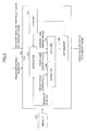
- FIG. 3 is a module diagram of an object tracking device according to an embodiment of the present disclosure.
- an object template (including its disparity map and its grayscale image) detected from a historical (prior) frame (image) as well as the disparity map and the grayscale image of a current frame are input and stored in the memory 101.
- a pedestrian template is taken as an example of the object template.
- the object may also include an animal having a torso and limbs, for example.
- a convex hull extractor also called an “extractor” for short
- a torso portion detector also called a “detector” for short
- a convex hull matcher also called a “matcher” for short
- an object determiner also called a “determiner” for short
- an object template updater also called an "updater” for short
- the extractor 103 may be configured to extract prior convex hulls in a pedestrian template (i.e., the object template) of the prior frame (also called a "prior pedestrian template").
- the prior convex hulls may include at least a prior torso convex hull and prior limb convex hulls.
- the extractor 103 may extract disparity-related connected components and their disparity-related outlines from the disparity map of the pedestrian template, then extract the principal gradient directions of the disparity-related outlines, and then extract the prior convex hulls on the grounds of the principal gradient directions.
- the extractor 103 may also be configured to extract current limb convex hulls from a surrounding region of a current torso portion in the current frame.
- the detector 104 may be configured to detect the current torso portion in the current frame on the basis of the grayscale feature and/or the disparity feature of the prior torso convex hull in the prior frame.
- the extractor 103 may extract the current limb convex hulls from the surrounding region of the current torso portion in the current frame.
- the matcher 105 may be configured to first calculate the difference between the principal gradient direction of each prior limb convex hull in the prior pedestrian template and the principal gradient direction of each current limb convex hull at the surrounding region of the current torso portion in the current frame; then rotate the current limb convex hulls at the surrounding region of the current torso portion in the current frame so as to let their principal gradient directions be consistent with the principal gradient direction of each prior limb convex hull in the prior pedestrian template; and then calculate the similarities between the images within the current limb convex hulls at the surrounding region of the current torso portion in the current frame and the image within each prior limb convex hull in the prior pedestrian template.
- the inputs are the prior limb convex hulls in the prior pedestrian template and the current limb convex hulls at the surrounding region of the current torso portion in the current frame
- the outputs are the matched current limb convex hulls at the surrounding region of the current torso portion in the current frame, corresponding to the prior limb convex hulls in the prior pedestrian template.
- the determiner 106 may be configured to determine, based on the matched current limb convex hulls, the position of the pedestrian in the current image. That is, the inputs are the matched current limb convex hulls, and the output is the pedestrian determined in the current image.
- the updater 107 may be configured to update the prior pedestrian template so as to obtain a current pedestrian template including the pedestrian in the current image, so that the current pedestrian template may serve as the prior pedestrian template of the next input frame.
- the inputs are the pedestrian determined in the current frame and the prior pedestrian template of the prior frame
- the output is the current pedestrian template including the pedestrian in the current frame.
- FIG. 4 is a flowchart of an object tracking method according to an embodiment of the present disclosure.
- the inputs are a prior pedestrian template (including its disparity map and its grayscale image) of a prior frame (image) as well as the disparity map and the grayscale image of a current frame (image).
- First prior convex hulls (including at least a prior torso convex hull and prior limb convex hulls) in the prior pedestrian template are extracted (STEP S101; also called a “first extraction step”). Then a portion in the current frame, corresponding to the prior torso convex hull is detected so as to serve as a current torso portion (STEP S102; also called a “detection step”). And then, current limb convex hulls at a surrounding region of the current torso portion in the current frame are extracted (STEP S103; also called a "second extraction step”).
- the principal gradient directions of the current limb convex hulls are rotated to be consistent with the principal gradient direction of the corresponding prior limb convex hull so as to seek a rotated current limb convex hull matching the corresponding prior limb convex hull (STEP S104; also called a "rotation step”).
- the positions of the limbs of the pedestrian in the current image are determined so as to determine the position of the pedestrian in the current image for realizing object tracking (STEP S105; also called a "determination step”).
- the prior pedestrian template is updated so as to acquire a current pedestrian template in the current frame (STEP S106; also called an "update step").
- STEPS S101 to S106 in FIG. 4 may be implemented by the extractor 103, the detector 104, the extractor 103, the matcher 105, the determiner 106, and the updater 107 in FIG. 3 , respectively.
- the torso portion of the pedestrian is usually unchanged when he/she moves, it is possible to utilize the prior pedestrian object template to detect the current torso portion of the pedestrian in the current frame so as to easily and accurately determine the position of the pedestrian in the current frame.
- the current limb convex hulls by extracting the current limb convex hulls from the surrounding portion of the current torso portion in the current frame, it is possible to accurately acquire the current limb convex hulls; that is, some noise-related convex hulls such as a trash can related convex hull and a bicycle related convex hull on the side of the relevant road may be easily excluded.
- FIG. 5 is a system sequence diagram of an object tracking method according to an embodiment of the present disclosure.
- the input unit 1100 may input a prior pedestrian template (including its disparity map and its grayscale image) detected in a historical (prior) frame (STEP S41) as well as the disparity map and the grayscale image of a current frame (STEP S42).
- a prior pedestrian template including its disparity map and its grayscale image detected in a historical (prior) frame (STEP S41) as well as the disparity map and the grayscale image of a current frame (STEP S42).
- the extractor extracts prior convex hulls (including at least a prior torso convex hull and prior limb convex hulls) from the prior pedestrian template (STEP S43).
- the detector detects a current torso portion of the pedestrian in the current frame, corresponding to the prior torso convex hull in the prior frame (STEP S44).
- the matcher conducts a matching process with respect to the prior limb convex hulls extracted from the prior pedestrian template and the current limb convex hulls extracted from a surrounding region of the current torso portion in the current frame (STEP S45).
- the determiner determines the position of the pedestrian in the current frame on the basis of the result of the matching process (STEP S46).
- the detected pedestrian in the current frame may be output by the output unit 1400 (STEP S47).
- the updater updates the prior pedestrian template so as to get a current pedestrian template (STEP S48).
- FIG. 6 illustrates the grayscale image and the disparity map of a prior pedestrian template as well as the grayscale image and the disparity map of a current frame.
- This prior pedestrian template is known, and may be one input from the outside, one defined by a user, or one updated according to the embodiments of the present disclosure.
- FIG. 7 is a module diagram of the extractor (i.e., the convex hull extractor).
- the input is a disparity map which is usually a sparse one.
- the sparse disparity map may be obtained by using a conventional technique, for example, image pre-processing, feature extraction, or point/feature matching. Since it is not necessary to acquire a dense disparity map, it is possible to further reduce the amount of calculation and speed up the calculation process.
- the output is a convex hull.
- the first module (also called a “connected component extraction module”) 1031 may extract a connected component from the disparity map.
- the second module also called an “outline extraction module” 1032 may extract the outline of the connected component.
- the third module (also called a "principal gradient direction extraction module”) 1033 may extract the principal gradient direction of the outline.
- the fourth module (also called a “convex hull extraction module”) 1034 may extract the convex hull on the grounds of the principal gradient direction of the outline.
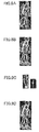
- FIGS. 8A to 8D illustrate a process of extracting convex hulls and obtaining their principal gradient directions.
- the prior convex hulls extracted from the prior pedestrian template may well express the torso, the limbs (e.g., the hands and the legs), the head, etc., of the pedestrian.
- the prior limb convex hulls of the pedestrian may be divided into upper arm convex hulls, lower arm convex hulls, hand palm convex hulls, upper leg convex hulls, lower leg convex hulls, foot convex hulls, and so on.
- a convex hull containing the upper convex hull and another convex hull containing the lower arm convex hull may be extracted, and the angle generated by these two convex hulls may also be the same angle (e.g., 120 degrees).
- the connected component extraction module 1031 may extract connected components from the disparity map of the prior pedestrian template.
- the outline extraction module 1032 may extract the outlines of the connected components.
- the principal gradient direction extraction module 1033 may extract the principal gradient directions of the outlines.
- the convex hull extraction module 1034 may extract the prior convex hulls on the basis of the principal gradient directions of the outlines.
- each outline is also a disparity-related one.
- the principal gradient direction of each of the outlines may be extracted, as presented in FIG. 8C .
- the principal gradient direction is a grayscale-related one which will be described in detail as follows.
- each pixel on each of the outlines of the connected components has a grayscale value (level).
- gradient x y g x , y + 1 ⁇ g x , y ⁇ 1 g x + 1 , y ⁇ g x , y ⁇ 1
- gradient(x,y) refers to the grayscale gradient of a pixel (x,y)
- g(x,y) stands for the grayscale value of the pixel (x,y).
- the principal gradient direction may be determined as follows. It is possible to divide a 360 degree space into plural subspaces each of which is a predetermined degree subspace.
- the predetermined degree subspace may be a 20 degree subspace, for example.
- the 360 degree space may be divided into subspaces [0,20], [20,40], and so on. After that, the number of pixels whose grayscale gradients are located in each subspace is counted, and a subspace having the maximum number of pixels is selected to serve as the principal gradient direction.
- the number of pixels whose grayscale gradients are located in a subspace [80,100] is maximum.
- the points forming the white line in the right image of FIG. 8C corresponds to the pixels located in the subspace. The longer the white line is, the bigger the number of pixels is.
- the formula (1) and the principal gradient direction mentioned above are two-dimensional ones.
- the present disclosure is not limited to this. Actually it is possible to know the relevant distance information from the disparity map of the prior pedestrian template, so it is also possible to adopt a three-dimensional principal gradient direction, and the follow-on rotation process is also a three-dimensional one.
- the three-dimensional grayscale gradient of each pixel on one of the outlines of the connected components may be calculated based on the following formulas (2) and (3).
- the follow-on rotation process may be successively conducted in the X-Y and Z-Y planes so as to realize the purpose of rotation in the three-dimensional space. In this way, it is possible to rotate a current convex hull so as to let its principal gradient direction be in the three-dimensional space in which the prior convex hulls are located, so that it is possible to acquire a more accurate matching result.
- the connected components are taken out on the basis of the principal gradient directions so that each of the connected components has only one principal gradient direction.
- the principal gradient direction of each of the prior convex hulls is reflected by the grayscale-related principal gradient directions of the pixels in the corresponding convex hull.
- the principal gradient direction of the convex hull of an upper arm when the upper arm is vertical to the ground is also vertical to the ground
- the principal gradient direction of the convex hull of a lower arm when the lower arm is horizontal to the ground is also horizontal to the ground.
- the convex hull extraction process is carried out twice, namely, when extracting the prior convex hulls from the pedestrian template of the prior frame and when extracting the convex limb convex hulls from the surrounding region of the current torso portion in the current frame.
- the convex hull extraction process is conducted with respect to only the pedestrian template of the prior frame so as to acquire the prior convex hulls including at least a prior torso convex hull, prior limb convex hulls, a prior head convex hull, etc.
- FIGS. 9A and 9B illustrate a process of extracting current limb convex hulls from a surrounding region of a current torso portion in the current image.
- a convex hull of the current torso portion in the current image is sought on the basis of the prior torso convex hull in the prior pedestrian template so as to serve as a current torso convex hull in the current frame (STEP S102 of FIG. 4 ).
- the distance information of the prior torso convex hull obtained from the disparity map of the prior pedestrian template so as to determine a region of interest in the current frame.
- the region of interest should be within a predetermined range of distance, the difference between any value in the predetermined range of distance and the distance of the prior torso convex hull being relatively small.
- the walking velocity or the moving velocity of the pedestrian may be estimated, i.e., has a certain range.
- seeking the convex hull of the current torso portion in the region of interest within the predetermined range of distance may have a better efficiency, save time, reduce the amount of calculation, and improve the accuracy of search.
- the torso portion of the pedestrian is unchanged when he/she walks.
- the torso portion of the pedestrian in the current frame may be detected by utilizing the prior pedestrian template of the prior frame, and the detection accuracy is also better.
- a surrounding region of the current torso portion in the current frame is divided into convex hulls. That is, the convex hulls are extracted from the surrounding region of the current torso portion so as so serve as current limb convex hulls in the current frame (STEP S103 of FIG. 4 ).
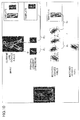
- FIG. 10 illustrates a process of rotating the principal gradient directions of two current limb convex hulls so as to let them be consistent with the principal gradient direction of a prior limb convex hull.
- the left lower leg of the pedestrian is taken as an example.
- FIG. 10 first the current limb convex hulls at the surrounding region (i.e., the region of interest) of the current portion in the current frame and the prior left lower leg convex hull in the prior pedestrian template of the prior frame (see the top of FIG. 10 ) are input.
- the prior left lower leg convex hull its outline and principal gradient direction may be acquired in the above-described convex hull extraction process.
- the current limb convex hull corresponding to the similarity S3 is chosen as the tracked left lower leg in the current frame because the similarity S 3 is greater than the similarity S 2 .
- the similarity S 3 is greater than the similarity S 2 .
- the position information of the prior left lower leg convex hull may also be considered so that it is possible to get a current left lower leg convex hull in the current frame which is not only more similar to the prior left lower leg convex hull but also has a suitable position.
- the prior left lower leg convex hull is focused on, it is possible to consider a current limb convex hull in the current frame which is located below the current torso portion therein and has a relatively large similarity.
- the current limb convex hull may be an upper or lower arm convex hull, i.e., may not be a lower leg convex hull because in general, when the pedestrian walks, his/her lower leg may not move to the side of his/her torso portion.
- the position information of the prior limb convex hulls in the prior frame is further taken into account, it is possible to more accurately obtain really matched current limb convex hulls in the current frame so as to determine their positions in the current frame.
- the position of the pedestrian is determined on the basis of the matched current limb convex hulls of the pedestrian in the current frame (STEP S105 of FIG. 4 ).
- by utilizing one or more limb convex hulls, for example, the convex hulls corresponding to the left lower leg, the left foot, and the left arm of the pedestrian it is possible to obtain his/her position in the current frame. In this way, it is possible to speed up the pedestrian detection and tracking process.
- FIG. 11 illustrates a result obtained by detecting the pedestrian in the current image.
- the updated pedestrian template is presented.
- FIG. 12 illustrates a computer system which may be applied to the embodiments of the present disclosure.
- the computer system includes a processor H1 and a storage H2 which is connected to the processor H1 and stores computer-executable instructions.
- the computer-executable instructions when executed by the processor H1, may cause the processor H1 to carry out the steps of the object tracking method shown in FIG. 4 .
- the steps of the object tracking method have been depicted in detail above, the repeated descriptions are omitted for the sake of convenience.
- the processor H1 may include one or more processors, microprocessors, etc.
- the storage H2 may include but is not limited to a RAM (Random Access Memory), a ROM (Read-Only Memory), a flash memory, an EPROM (Erasable Programmable Read-Only Memory), an EEPROM (Electrically Erasable Programmable Read-Only Memory), a register, a hard disk, a floppy disk, a CD-ROM (Compact Disc Read-Only Memory), a DVD-ROM (Digital Versatile Disk Read-Only Memory), etc.
- the computer system presented in FIG. 12 may also include a data bus H3, a RAM H4, an I/O (Input/Output) bus H5, a display H6, and a peripheral device which may be conventional ones, for example.
- a data bus H3 a RAM H4
- an I/O (Input/Output) bus H5 a display H6, and a peripheral device which may be conventional ones, for example.
- the embodiments of the present disclosure may be implemented in any convenient form, for example, using dedicated hardware or a mixture of dedicated hardware and software.
- the embodiments of the present disclosure may be implemented as computer software implemented by one or more networked processing apparatuses.
- the network may comprise any conventional terrestrial or wireless communications network, such as the Internet.
- the processing apparatuses may comprise any suitably programmed apparatuses such as a general-purpose computer, a personal digital assistant, a mobile telephone (such as a WAP or 3G-compliant phone) and so on. Since the embodiments of the present disclosure can be implemented as software, each and every aspect of the present disclosure thus encompasses computer software implementable on a programmable device.
- the computer software may be provided to the programmable device using any storage medium for storing processor-readable code such as a floppy disk, a hard disk, a CD ROM, a magnetic tape device or a solid state memory device.
- the hardware platform includes any desired hardware resources including, for example, a central processing unit (CPU), a random access memory (RAM), and a hard disk drive (HDD).
- the CPU may include processors of any desired type and number.
- the RAM may include any desired volatile or nonvolatile memory.
- the HDD may include any desired nonvolatile memory capable of storing a large amount of data.
- the hardware resources may further include an input device, an output device, and a network device in accordance with the type of the apparatus.
- the HDD may be provided external to the apparatus as long as the HDD is accessible from the apparatus.
- the CPU for example, the cache memory of the CPU, and the RAM may operate as a physical memory or a primary memory of the apparatus, while the HDD may operate as a secondary memory of the apparatus.
Landscapes
- Engineering & Computer Science (AREA)
- Theoretical Computer Science (AREA)
- Physics & Mathematics (AREA)
- General Physics & Mathematics (AREA)
- Computer Vision & Pattern Recognition (AREA)
- Multimedia (AREA)
- Human Computer Interaction (AREA)
- Health & Medical Sciences (AREA)
- General Health & Medical Sciences (AREA)
- Psychiatry (AREA)
- Social Psychology (AREA)
- Artificial Intelligence (AREA)
- Computing Systems (AREA)
- Databases & Information Systems (AREA)
- Evolutionary Computation (AREA)
- Medical Informatics (AREA)
- Software Systems (AREA)
- Image Analysis (AREA)
Abstract
Description
- The present disclosure relates to the field of computer stereo vision, more particularly relates to a method, device, and system for tracking an object in a disparity map as well as the relevant program and non-transitory computer-readable medium.
- The application of computer stereo vision is related to the fields of driving assistance, automatic recognition and tracking, driving early warning, and so on. In the application of computer stereo vision for intelligent driving, it is very important to track an object such as a pedestrian or an animal, particularly in a city scene. However, because of the change of the posture of the object, the change of the relevant background, and the change of the distance to the object, it is very difficult to track the object when it moves.
- Therefore, it is necessary to develop a kind of technique able to track an object in a disparity map.
- According to a first aspect of the present disclosure, a method for tracking an object in a disparity map is provided. The method may include:
- extracting prior convex hulls in an object template of a prior frame (image), the prior convex hulls including at least a prior torso convex hull and prior limb convex hulls;
- detecting a portion corresponding to the prior torso convex hull, in a current frame (image) so as to serve as a current torso portion;
- extracting current limb convex hulls from a surrounding region of the current torso portion in the current frame;
- for each of the prior limb convex hulls, rotating, based on principal gradient directions of the current limb convex hulls and the prior limb convex hulls, each of the current limb convex hulls so as to let the principal gradient direction of the corresponding current limb convex hull be consistent with the principal gradient direction of the corresponding prior limb convex hull;
- seeking rotated current limb convex hulls matching the prior limb convex hulls, respectively; and
- determining, based on the matching results, an object template in the current frame so as to achieve object tracking.
- According to a second aspect of the present disclosure, a device for tracking an object in a disparity map is provided. The device may include an extractor, a detector, a matcher, and a determiner.
- The extractor is configured to extract prior convex hulls in an object template of a prior frame (image), the prior convex hulls including at least a prior torso convex hull and prior limb convex hulls.
- The detector is configured to detect a portion corresponding to the prior torso convex hull, in a current frame (image) so as to serve as a current torso portion.
- The extractor is further configured to extract current limb convex hulls from a surrounding region of the current torsos portion in the current frame.
- The matcher is configured, for each of the prior limb convex hulls, to rotate, based on principal gradient directions of the current limb convex hulls and the prior limb convex hulls, each of the current limb convex hulls to let the principal gradient direction of the corresponding current limb convex hull be consistent with the principal gradient direction of the corresponding prior limb convex hull so as to seek a rotated current limb convex hull matching the corresponding prior limb convex hull.
- The determiner is configured to determine, based on the matching results, an object template in the current frame so as to achieve object tracking.
- According to a third aspect of the present disclosure, a system for tracking an object in a disparity map is provided. The system may include:
- a processor; and
- a storage connected to the processor, storing computer-executable instructions which, when executed, cause the processor to carry out the above-described method for tracking an object in a disparity map.
- According to a fourth aspect of the present disclosure, a program for causing a computer to carry out the above-described method for tracking an object in a disparity map is provided.
- According to a fifth aspect of the present disclosure, a non-transitory computer-readable medium storing computer-executable instructions for execution by a processing system is provided. The computer-executable instructions, when executed, cause the processing system to carry out the above-described method for tracking an object in a disparity map.
-
-
FIG. 1 illustrates a hardware configuration which may be applied to the embodiments of the present disclosure; -
FIG. 2 illustrates an application environment which may be applied to the embodiments of the present disclosure; -
FIG. 3 is a module diagram of a device for tracking an object in a disparity map, according to an embodiment of the present disclosure; -
FIG. 4 is a flowchart of a method for tracking an object in a disparity map, according to an embodiment of the present disclosure; -
FIG. 5 is a system sequence diagram of a method for tracking an object in a disparity map, according to an embodiment of the present disclosure; -
FIG. 6 illustrates the grayscale image of a prior object template and its disparity map as well as a current grayscale image and its disparity map; -
FIG. 7 is a module diagram of a convex hull extractor; -
FIGS. 8A to 8D illustrate a process of extracting convex hulls and obtaining their principal gradient directions; -
FIGS. 9A to 9B illustrate a process of extracting current limb convex hulls from a surrounding region of a current torso portion in a current frame; -
FIG. 10 illustrates a process of rotating the principal gradient directions of two current limb convex hulls so as to let them be consistent with the principal gradient direction of a prior limb convex hull; -
FIG. 11 illustrates a result obtained by detecting an object in a current image; and -
FIG. 12 illustrates a system for tracking an object in a disparity map, according to an embodiment of the present disclosure. - In order to let those people skilled in the art better understand the present disclosure, hereinafter, the embodiments of the present disclosure will be concretely described with reference to the drawings. However it should be noted that the same symbols, which are in the specification and the drawings, stand for the constructional elements having basically the same function and structure, and the repeated explanations for the constructional elements are omitted.
-
FIG. 1 illustrates a hardware configuration which may be applied to the embodiments of the present disclosure. - As presented in
FIG. 1 , the hardware configuration includes aninput device 1100, a CPU (Central Processing Unit) 1200, astorage device 1300, and anoutput device 1400. - The
input device 1100 may be configured to input a disparity map, road's vanishing point/line related information, etc. Thecentral processing unit 1200 may be configured to execute an object tracking method according to the embodiments of the present disclosure. Thestorage device 1300 may be configured to store the relevant data and information. And theoutput device 1400 may be configured to output the tracked object. -
FIG. 2 illustrates an application environment which may be applied to the embodiments of the present disclosure. - As presented in
FIG. 2 , a two-lens camera may be mounted on a vehicle, and may be used to obtain right and left images. In addition, a chip may be utilized to conduct an object tracking method according to the embodiments of the present disclosure. -
FIG. 3 is a module diagram of an object tracking device according to an embodiment of the present disclosure. - As presented in
FIG. 3 , an object template (including its disparity map and its grayscale image) detected from a historical (prior) frame (image) as well as the disparity map and the grayscale image of a current frame are input and stored in thememory 101. Here it should be noted that in what follows, a pedestrian template is taken as an example of the object template. However, the present disclosure is not limited to this. The object may also include an animal having a torso and limbs, for example. - In the central processing unit (CPU) 102, five modules, i.e., a convex hull extractor (also called an "extractor" for short) 103, a torso portion detector (also called a "detector" for short) 104, a convex hull matcher (also called a "matcher" for short) 105, an object determiner (also called a "determiner" for short) 106, and an object template updater (also called an "updater" for short) 107 which is optional, may be used to process the relevant data and information, so as to output the tracked object in the current frame.
- The
extractor 103 may be configured to extract prior convex hulls in a pedestrian template (i.e., the object template) of the prior frame (also called a "prior pedestrian template"). The prior convex hulls may include at least a prior torso convex hull and prior limb convex hulls. In particular, theextractor 103 may extract disparity-related connected components and their disparity-related outlines from the disparity map of the pedestrian template, then extract the principal gradient directions of the disparity-related outlines, and then extract the prior convex hulls on the grounds of the principal gradient directions. Aside from this, theextractor 103 may also be configured to extract current limb convex hulls from a surrounding region of a current torso portion in the current frame. - Here it should be noted that since the concept of a convex hull is well known to those skilled in the art, the detailed description is omitted. For more information, it is also possible to see https://en.wikipedia.org/wiki/Convex_hull.
- In addition, how to extract a convex hull is also well known to those skilled in the art. For example, it is possible to adopt the Gift wrapping algorithm, the Graham's scan algorithm, or the Melkman's algorithm to carry out convex hull extraction. Here, for the sake of convenience, the detailed description is also omitted.
- The
detector 104 may be configured to detect the current torso portion in the current frame on the basis of the grayscale feature and/or the disparity feature of the prior torso convex hull in the prior frame. - After that, the
extractor 103 may extract the current limb convex hulls from the surrounding region of the current torso portion in the current frame. - The
matcher 105 may be configured to first calculate the difference between the principal gradient direction of each prior limb convex hull in the prior pedestrian template and the principal gradient direction of each current limb convex hull at the surrounding region of the current torso portion in the current frame; then rotate the current limb convex hulls at the surrounding region of the current torso portion in the current frame so as to let their principal gradient directions be consistent with the principal gradient direction of each prior limb convex hull in the prior pedestrian template; and then calculate the similarities between the images within the current limb convex hulls at the surrounding region of the current torso portion in the current frame and the image within each prior limb convex hull in the prior pedestrian template. In this way, it is possible to determine the current limb convex hulls having the highest similarities, at the surrounding region of the current torso portion in the current frame as matched ones of the prior limb convex hulls in the prior pedestrian template, respectively. In other words, the inputs are the prior limb convex hulls in the prior pedestrian template and the current limb convex hulls at the surrounding region of the current torso portion in the current frame, and the outputs are the matched current limb convex hulls at the surrounding region of the current torso portion in the current frame, corresponding to the prior limb convex hulls in the prior pedestrian template. - The
determiner 106 may be configured to determine, based on the matched current limb convex hulls, the position of the pedestrian in the current image. That is, the inputs are the matched current limb convex hulls, and the output is the pedestrian determined in the current image. - The
updater 107 may be configured to update the prior pedestrian template so as to obtain a current pedestrian template including the pedestrian in the current image, so that the current pedestrian template may serve as the prior pedestrian template of the next input frame. In other words, the inputs are the pedestrian determined in the current frame and the prior pedestrian template of the prior frame, and the output is the current pedestrian template including the pedestrian in the current frame. -
FIG. 4 is a flowchart of an object tracking method according to an embodiment of the present disclosure. - The inputs are a prior pedestrian template (including its disparity map and its grayscale image) of a prior frame (image) as well as the disparity map and the grayscale image of a current frame (image).
- First prior convex hulls (including at least a prior torso convex hull and prior limb convex hulls) in the prior pedestrian template are extracted (STEP S101; also called a "first extraction step"). Then a portion in the current frame, corresponding to the prior torso convex hull is detected so as to serve as a current torso portion (STEP S102; also called a "detection step"). And then, current limb convex hulls at a surrounding region of the current torso portion in the current frame are extracted (STEP S103; also called a "second extraction step"). After that, on the grounds of the principal gradient directions of the current limb convex hulls and the prior limb convex hulls, regarding each of the prior limb convex hulls, the principal gradient directions of the current limb convex hulls are rotated to be consistent with the principal gradient direction of the corresponding prior limb convex hull so as to seek a rotated current limb convex hull matching the corresponding prior limb convex hull (STEP S104; also called a "rotation step"). Finally, on the basis of the matched results, the positions of the limbs of the pedestrian in the current image are determined so as to determine the position of the pedestrian in the current image for realizing object tracking (STEP S105; also called a "determination step"). Optionally the prior pedestrian template is updated so as to acquire a current pedestrian template in the current frame (STEP S106; also called an "update step").
- Here it should be noted that STEPS S101 to S106 in
FIG. 4 may be implemented by theextractor 103, thedetector 104, theextractor 103, thematcher 105, thedeterminer 106, and theupdater 107 inFIG. 3 , respectively. - In this way, since the torso portion of the pedestrian is usually unchanged when he/she moves, it is possible to utilize the prior pedestrian object template to detect the current torso portion of the pedestrian in the current frame so as to easily and accurately determine the position of the pedestrian in the current frame. Moreover, by extracting the current limb convex hulls from the surrounding portion of the current torso portion in the current frame, it is possible to accurately acquire the current limb convex hulls; that is, some noise-related convex hulls such as a trash can related convex hull and a bicycle related convex hull on the side of the relevant road may be easily excluded. Furthermore, by analyzing the differences between the principal gradient directions of the current limb convex hulls in the current frame and the principal gradient directions of the prior limb convex hulls in the prior frame and rotating the principal gradient directions of the current limb convex hulls in the current frame to be consistent with the principal gradient direction of each of the prior limb convex hulls (e.g., a known right leg convex hull) in the prior frame, it is possible to easily determine whether the current limb convex hulls in the current frame match the respective prior limb convex hulls. In this way, it is possible to accurately determine which prior limb convex hull in the prior frame each of the current convex hulls in the current frame matches, so that it is possible to determine the exact positions of the limbs of the pedestrian in the current frame so as to determine the position of the pedestrian in the current frame. After that, by updating the prior pedestrian template so as to get a current pedestrian template including the pedestrian in the current frame, it is also possible to let the object detection and tracking process conducted with respect to the next input frame be easier and more accurate. As a result, the object detection and tracking process according to the embodiments of the present disclosure is accurate and easy to perform, and its calculation amount and time may be dramatically reduced.
-
FIG. 5 is a system sequence diagram of an object tracking method according to an embodiment of the present disclosure. - As presented in
FIG. 5 , theinput unit 1100 may input a prior pedestrian template (including its disparity map and its grayscale image) detected in a historical (prior) frame (STEP S41) as well as the disparity map and the grayscale image of a current frame (STEP S42). - In the pedestrian tracking device, the extractor extracts prior convex hulls (including at least a prior torso convex hull and prior limb convex hulls) from the prior pedestrian template (STEP S43). The detector detects a current torso portion of the pedestrian in the current frame, corresponding to the prior torso convex hull in the prior frame (STEP S44). The matcher conducts a matching process with respect to the prior limb convex hulls extracted from the prior pedestrian template and the current limb convex hulls extracted from a surrounding region of the current torso portion in the current frame (STEP S45). The determiner determines the position of the pedestrian in the current frame on the basis of the result of the matching process (STEP S46). Here the detected pedestrian in the current frame may be output by the output unit 1400 (STEP S47). After that, the updater updates the prior pedestrian template so as to get a current pedestrian template (STEP S48).
-
FIG. 6 illustrates the grayscale image and the disparity map of a prior pedestrian template as well as the grayscale image and the disparity map of a current frame. - On the top of
FIG. 6 are the grayscale image and the disparity map of the prior pedestrian template. This prior pedestrian template is known, and may be one input from the outside, one defined by a user, or one updated according to the embodiments of the present disclosure. - In addition, on the bottom of
FIG. 6 are the grayscale image and the disparity map of the current frame. In the embodiments of the present disclosure, it is possible to detect the position of the pedestrian in the current frame, matching the prior pedestrian template of the prior frame, as described above. -
FIG. 7 is a module diagram of the extractor (i.e., the convex hull extractor). - As presented in
FIG. 7 , the input is a disparity map which is usually a sparse one. The sparse disparity map may be obtained by using a conventional technique, for example, image pre-processing, feature extraction, or point/feature matching. Since it is not necessary to acquire a dense disparity map, it is possible to further reduce the amount of calculation and speed up the calculation process. - The output is a convex hull.
- In particular, the first module (also called a "connected component extraction module") 1031 may extract a connected component from the disparity map. The second module (also called an "outline extraction module") 1032 may extract the outline of the connected component. The third module (also called a "principal gradient direction extraction module") 1033 may extract the principal gradient direction of the outline. The fourth module (also called a "convex hull extraction module") 1034 may extract the convex hull on the grounds of the principal gradient direction of the outline.
-
FIGS. 8A to 8D illustrate a process of extracting convex hulls and obtaining their principal gradient directions. - As described above, in STEP S101 of
FIG. 4 , it is possible to extract prior convex hulls from the disparity map of a prior pedestrian template. Here, since it is possible to adopt a conventional algorithm, for example, the Gift wrapping algorithm, the Graham's scan algorithm, or the Melkman's algorithm to carry out convex hull extraction, the detailed description is omitted for the sake of convenience. - As is well known, one of the characteristics of a convex hull is that any point on any line segment, whose two ends are located within the convex hull, is also within the convex hull. As such, the prior convex hulls extracted from the prior pedestrian template may well express the torso, the limbs (e.g., the hands and the legs), the head, etc., of the pedestrian. In addition, the prior limb convex hulls of the pedestrian may be divided into upper arm convex hulls, lower arm convex hulls, hand palm convex hulls, upper leg convex hulls, lower leg convex hulls, foot convex hulls, and so on. As such, for example, in a case where the upper arm and the lower arm of an arm form an angle (e.g., 120 degrees), a convex hull containing the upper convex hull and another convex hull containing the lower arm convex hull may be extracted, and the angle generated by these two convex hulls may also be the same angle (e.g., 120 degrees).
- As a result, even if the angle formed by the upper arm and the lower arm of the arm of the pedestrian in the current frame is changed, for example, becomes 150 degrees, it is also possible to conduct the above-described rotation step (i.e., STEP S104 in
FIG. 4 ) so as to obtain a good matching result. However, in the conventional technique, since the whole arm in the current frame is compared with the whole arm in the prior pedestrian template when determining whether the two match each other, if the angle generated by the upper and lower arms of the arm in the current frame is different from the angle formed by the two in the prior pedestrian template, then it may be impossible to get a correct matching result. - Particularly, in STEP S101 of
FIG. 4 , the connectedcomponent extraction module 1031 may extract connected components from the disparity map of the prior pedestrian template. Theoutline extraction module 1032 may extract the outlines of the connected components. The principal gradientdirection extraction module 1033 may extract the principal gradient directions of the outlines. And the convexhull extraction module 1034 may extract the prior convex hulls on the basis of the principal gradient directions of the outlines. - In what follows, the process of STEP S101 in
FIG. 4 will be depicted in detail. - First a CCA (Connected Component Analysis) approach is utilized for extracting the connected components from the disparity map of the prior pedestrian template. In order to seek all the connected components in the disparity map, it is possible to adopt a BFS (Breadth First Search) algorithm. Since more information about the CCA approach and the BFS algorithm may be accessed by referring to https://en.wikipedia.org/wiki/Connected component (graph theory), the repeated description is omitted for the sake of convenience. Here it should be noted that each of the connected components is a disparity-related one. In addition, the connected components extracted are presented in
FIG. 8A in which each circle/ellipse represents a connected component. - Next the outline of each of the connected components may be extracted, as presented in
FIG. 8B . Of course, each outline is also a disparity-related one. - After that, the principal gradient direction of each of the outlines may be extracted, as presented in
FIG. 8C . Here it should be noted that the principal gradient direction is a grayscale-related one which will be described in detail as follows. - In the grayscale image of the prior pedestrian template, each pixel on each of the outlines of the connected components has a grayscale value (level). According to the following formula (1), it is possible to calculate the grayscale gradient of each pixel on one of the outline, as presented in the left image of
FIG. 8C .
- Here, gradient(x,y) refers to the grayscale gradient of a pixel (x,y), and g(x,y) stands for the grayscale value of the pixel (x,y).
- The principal gradient direction may be determined as follows. It is possible to divide a 360 degree space into plural subspaces each of which is a predetermined degree subspace. The predetermined degree subspace may be a 20 degree subspace, for example. In this case, the 360 degree space may be divided into subspaces [0,20], [20,40], and so on. After that, the number of pixels whose grayscale gradients are located in each subspace is counted, and a subspace having the maximum number of pixels is selected to serve as the principal gradient direction.
- For example, as presented in the right image of
FIG. 8C , the number of pixels whose grayscale gradients are located in a subspace [80,100] is maximum. Here it should be noted that the points forming the white line in the right image ofFIG. 8C corresponds to the pixels located in the subspace. The longer the white line is, the bigger the number of pixels is. - Of course, the formula (1) and the principal gradient direction mentioned above are two-dimensional ones. However, the present disclosure is not limited to this. Actually it is possible to know the relevant distance information from the disparity map of the prior pedestrian template, so it is also possible to adopt a three-dimensional principal gradient direction, and the follow-on rotation process is also a three-dimensional one.
- In this case, the three-dimensional grayscale gradient of each pixel on one of the outlines of the connected components may be calculated based on the following formulas (2) and (3).


- After that, it is possible to derive an angle θ on the X-Y plane from the formula (2), and an angle α on the Z-Y plane from the formula (3). As such, the follow-on rotation process may be successively conducted in the X-Y and Z-Y planes so as to realize the purpose of rotation in the three-dimensional space. In this way, it is possible to rotate a current convex hull so as to let its principal gradient direction be in the three-dimensional space in which the prior convex hulls are located, so that it is possible to acquire a more accurate matching result.
- Finally the prior convex hulls are extracted on the grounds of the principal gradient directions of the outlines of the connected components.
- In particular, the connected components are taken out on the basis of the principal gradient directions so that each of the connected components has only one principal gradient direction. In this way, it is possible to obtain the prior convex hulls, as presented in
FIG. 8D . Here it should be noted that in the embodiments of the present disclosure, the principal gradient direction of each of the prior convex hulls is reflected by the grayscale-related principal gradient directions of the pixels in the corresponding convex hull. - For example, the principal gradient direction of the convex hull of an upper arm when the upper arm is vertical to the ground is also vertical to the ground, and the principal gradient direction of the convex hull of a lower arm when the lower arm is horizontal to the ground is also horizontal to the ground. As such, it is possible to easily use the principal gradient directions to estimate the orientation of the prior convex hulls (which are usually the long-side directions of the prior convex hulls).
- As a result, by the above-describe step, it is possible to rapidly extract the prior convex hulls from the prior pedestrian template and obtain the principal gradient direction of each of the prior convex hulls.
- Here it should be noted that as described above, the convex hull extraction process is carried out twice, namely, when extracting the prior convex hulls from the pedestrian template of the prior frame and when extracting the convex limb convex hulls from the surrounding region of the current torso portion in the current frame. In STEP S101 of
FIG. 4 , the convex hull extraction process is conducted with respect to only the pedestrian template of the prior frame so as to acquire the prior convex hulls including at least a prior torso convex hull, prior limb convex hulls, a prior head convex hull, etc. -
FIGS. 9A and 9B illustrate a process of extracting current limb convex hulls from a surrounding region of a current torso portion in the current image. - First a convex hull of the current torso portion in the current image is sought on the basis of the prior torso convex hull in the prior pedestrian template so as to serve as a current torso convex hull in the current frame (STEP S102 of
FIG. 4 ). - Here it is possible to use the distance information of the prior torso convex hull obtained from the disparity map of the prior pedestrian template so as to determine a region of interest in the current frame. In general, the region of interest should be within a predetermined range of distance, the difference between any value in the predetermined range of distance and the distance of the prior torso convex hull being relatively small. The reason is that the walking velocity or the moving velocity of the pedestrian may be estimated, i.e., has a certain range. As such, seeking the convex hull of the current torso portion in the region of interest within the predetermined range of distance may have a better efficiency, save time, reduce the amount of calculation, and improve the accuracy of search.
- In addition, it is also possible to conduct a template matching process based on the color of the torso portion in the prior frame so as to find a corresponding torso portion in the current frame to serve as the current torso portion therein. Generally speaking, the torso portion of the pedestrian is unchanged when he/she walks. As such, the torso portion of the pedestrian in the current frame may be detected by utilizing the prior pedestrian template of the prior frame, and the detection accuracy is also better.
- Next a surrounding region of the current torso portion in the current frame is divided into convex hulls. That is, the convex hulls are extracted from the surrounding region of the current torso portion so as so serve as current limb convex hulls in the current frame (STEP S103 of
FIG. 4 ). - In particular, it is possible to use the convex hull extraction algorithm described above by referring to
FIGS. 7 and8A to 8D to divide the surrounding region of the current torso portion in the current frame into convex hulls. Here it should be noted that by extracting the convex hulls from the surrounding region of the current torso portion in the current frame, it is possible to accurately obtain the current limb convex hulls, i.e., it is possible to easily remove some noise related convex hulls such as a trash can related convex hull and a bicycle related convex hull on the side of the relevant road. -
FIG. 10 illustrates a process of rotating the principal gradient directions of two current limb convex hulls so as to let them be consistent with the principal gradient direction of a prior limb convex hull. - First a rotation process is conducted with respect to the prior limb convex hulls in the prior pedestrian template of the prior frame and the current limb convex hulls at the surrounding region of the current torso portion in the current frame on the grounds of their principal gradient directions (STEP S104 of
FIG. 4 ). - Here the left lower leg of the pedestrian is taken as an example. In
FIG. 10 , first the current limb convex hulls at the surrounding region (i.e., the region of interest) of the current portion in the current frame and the prior left lower leg convex hull in the prior pedestrian template of the prior frame (see the top ofFIG. 10 ) are input. Here, regarding the prior left lower leg convex hull, its outline and principal gradient direction may be acquired in the above-described convex hull extraction process. Then, by calculating the differences θ2 and θ3 between the principal gradient direction of the prior left lower leg and the principal gradient directions of two current limb convex hulls at the region of interest in the current frame, it is possible to rotate the two current limb convex hulls on the basis of the differences θ2 and θ3 so as to let their principal gradient directions be the same as the principal gradient direction of the prior left lower leg convex hull. And then, an image matching process is carried out so as to obtain two similarities S2 and S3 between the two rotated current limb convex hulls and the prior left lower leg convex hull. As a result, it is possible to find one of the two current limb convex hulls after rotation which is more similar to the prior left lower leg convex hull so as to serve as the tracked left lower leg in the current frame. InFIG. 10 , the current limb convex hull corresponding to the similarity S3 is chosen as the tracked left lower leg in the current frame because the similarity S3 is greater than the similarity S2. Here it should be noted that since there are many well-known approaches capable of realizing the image matching process such as a color feature based one, a shape feature based one, a gradient feature based one, and so forth, the detailed descriptions are omitted. - Preferably, aside from the image matching process, the position information of the prior left lower leg convex hull may also be considered so that it is possible to get a current left lower leg convex hull in the current frame which is not only more similar to the prior left lower leg convex hull but also has a suitable position. For example, in this case, since the prior left lower leg convex hull is focused on, it is possible to consider a current limb convex hull in the current frame which is located below the current torso portion therein and has a relatively large similarity. That is, if a current limb convex hull having a higher similarity is not located below the current torso portion, for example, by the side of the current torso portion, then the current limb convex hull may be an upper or lower arm convex hull, i.e., may not be a lower leg convex hull because in general, when the pedestrian walks, his/her lower leg may not move to the side of his/her torso portion. As such, if the position information of the prior limb convex hulls in the prior frame is further taken into account, it is possible to more accurately obtain really matched current limb convex hulls in the current frame so as to determine their positions in the current frame.
- After that, the position of the pedestrian is determined on the basis of the matched current limb convex hulls of the pedestrian in the current frame (STEP S105 of
FIG. 4 ). Of course, in order to determine the position of the pedestrian, it is not necessary to use all the matched current limb convex hulls of the pedestrian in the current frame. In general, by utilizing one or more limb convex hulls, for example, the convex hulls corresponding to the left lower leg, the left foot, and the left arm of the pedestrian, it is possible to obtain his/her position in the current frame. In this way, it is possible to speed up the pedestrian detection and tracking process. Again, for example, by using the convex hulls corresponding to the right lower leg, the right foot, and the right arm of the pedestrian, it is possible to acquire his/her position in the current frame. Especially in a case where the speed of the pedestrian detection and tracking process needs to be first considered, by utilizing only the convex hulls of the right lower leg and the right foot of the pedestrian, it is also possible to determine his/her position in the current frame, so that pedestrian detection and tracking process may be further speeded up. -
FIG. 11 illustrates a result obtained by detecting the pedestrian in the current image. - In
FIG. 11 , the updated pedestrian template is presented. As such, on the grounds of the updated pedestrian template, it is possible to know the newest state of the pedestrian in the current frame so that it is possible to solve the problem that the shape and the size of the pedestrian in the related image may change, and it is also possible to reduce the calculation amount and save the calculation cost and time. -
FIG. 12 illustrates a computer system which may be applied to the embodiments of the present disclosure. - As presented in
FIG. 12 , the computer system includes a processor H1 and a storage H2 which is connected to the processor H1 and stores computer-executable instructions. The computer-executable instructions, when executed by the processor H1, may cause the processor H1 to carry out the steps of the object tracking method shown inFIG. 4 . Here it should be noted that since the steps of the object tracking method have been depicted in detail above, the repeated descriptions are omitted for the sake of convenience. - The processor H1 may include one or more processors, microprocessors, etc. And the storage H2 may include but is not limited to a RAM (Random Access Memory), a ROM (Read-Only Memory), a flash memory, an EPROM (Erasable Programmable Read-Only Memory), an EEPROM (Electrically Erasable Programmable Read-Only Memory), a register, a hard disk, a floppy disk, a CD-ROM (Compact Disc Read-Only Memory), a DVD-ROM (Digital Versatile Disk Read-Only Memory), etc.
- Furthermore the computer system presented in
FIG. 12 may also include a data bus H3, a RAM H4, an I/O (Input/Output) bus H5, a display H6, and a peripheral device which may be conventional ones, for example. - Up to here, the preferred embodiments of the present disclosure have been illustrated in detail. However, it should be noted that the above embodiments are just exemplary ones, and the specific structure and operation of them may not be used for limiting the present disclosure.
- Moreover, the embodiments of the present disclosure may be implemented in any convenient form, for example, using dedicated hardware or a mixture of dedicated hardware and software. The embodiments of the present disclosure may be implemented as computer software implemented by one or more networked processing apparatuses. The network may comprise any conventional terrestrial or wireless communications network, such as the Internet. The processing apparatuses may comprise any suitably programmed apparatuses such as a general-purpose computer, a personal digital assistant, a mobile telephone (such as a WAP or 3G-compliant phone) and so on. Since the embodiments of the present disclosure can be implemented as software, each and every aspect of the present disclosure thus encompasses computer software implementable on a programmable device.
- The computer software may be provided to the programmable device using any storage medium for storing processor-readable code such as a floppy disk, a hard disk, a CD ROM, a magnetic tape device or a solid state memory device.
- The hardware platform includes any desired hardware resources including, for example, a central processing unit (CPU), a random access memory (RAM), and a hard disk drive (HDD). The CPU may include processors of any desired type and number. The RAM may include any desired volatile or nonvolatile memory. The HDD may include any desired nonvolatile memory capable of storing a large amount of data. The hardware resources may further include an input device, an output device, and a network device in accordance with the type of the apparatus. The HDD may be provided external to the apparatus as long as the HDD is accessible from the apparatus. In this case, the CPU, for example, the cache memory of the CPU, and the RAM may operate as a physical memory or a primary memory of the apparatus, while the HDD may operate as a secondary memory of the apparatus.
- While the present disclosure is described with reference to the specific embodiments chosen for purpose of illustration, it should be apparent that the present disclosure is not limited to these embodiments, but numerous modifications could be made thereto by those people skilled in the art without departing from the basic concept and technical scope of the present disclosure.
- The present application is based on and claims the benefit of priority of Chinese Patent Application No.
201510622651.9 filed on Sep. 25, 2015
Claims (12)
- A method for tracking an object in a disparity map, comprising:extracting prior convex hulls in an object template of a prior frame, the prior convex hulls including at least a prior torso convex hull and prior limb convex hulls;detecting a portion corresponding to the prior torso convex hull, in a current frame so as to serve as a current torso portion;extracting current limb convex hulls from a surrounding region of the current torsos portion in the current frame;for each of the prior limb convex hulls, rotating, based on principal gradient directions of the current limb convex hulls and the prior limb convex hulls, each of the current limb convex hulls so as to let the principal gradient direction of the current limb convex hull be consistent with the principal gradient direction of the corresponding prior limb convex hull;seeking rotated current limb convex hulls matching the prior limb convex hulls, respectively; anddetermining, based on the matching results, an object template in the current frame so as to achieve object tracking.
- The method according to claim 1, wherein the convex hulls are extracted by carrying out:extracting connected components from a corresponding disparity map;for each of the connected components, extracting its outline;for each of the outlines of the connected components, obtaining, based on a grayscale value of each pixel on the corresponding outline in a corresponding grayscale image, a grayscale-related gradient of each pixel on the corresponding outline;dividing a space relevant to each of the connected components into subspaces;for each of the subspaces relevant to each of the connected components, counting a number of pixels whose grayscale-related gradients are within the corresponding subspace;for each of the connected components, selecting a subspace having the maximum number of pixels to serve as a principal gradient direction of the corresponding connected component; andrespectively extracting, based on the principal gradient directions of the connected components, the convex hulls from the connected components, so as to let each of the convex hulls have only one principal gradient direction.
- The method according to claim 1 or 2, wherein the detection step incudes:determining, based on a distance of the prior torso convex hull in a corresponding disparity map, a region of interest in the current frame, the distance of the region of interest and the distance of the prior torso convex hull being less than a first predetermined threshold; anddetecting, based on a color template, a portion in the region of interest of the current frame, matching the prior torso convex hull so as to serve as the current torso portion.
- The method according to claim 1, 2 or 3, wherein the rotation step includes:determining, based on a distance of each of the prior limb convex hulls in a corresponding disparity map, a region of interest in the current frame, a distance of the region of interest and the distance of each of the prior limb convex hulls being less than a second predetermined threshold; andfor each of the prior limb convex hulls, rotating a principal gradient direction of each of the current convex hulls in the region of interest of the current frame so as to be consistent with a principal gradient direction of the corresponding prior limb convex hull.
- The method according to any one preceding claim, wherein the seeking step includes:for each of the prior limb convex hulls, finding a rotated current limb convex hull matching the corresponding prior limb convex hull by taking into account a position of the corresponding prior limb convex hull, a position of the rotated current limb convex hull being located within a range that the corresponding prior limb convex hull may move therein.
- The method according to any one preceding claim, wherein the rotation step is carried out in a two-dimensional space or a three-dimensional space.
- The method according to any one preceding claim, wherein the disparity map is a sparse one.
- The method according to any one preceding claim, wherein the object template in the current frame is determined based on at least one of the matching results.
- A device for tracking an object in a disparity map, comprising an extractor, a detector, a matcher, and a determiner, wherein:the extractor is configured to extract prior convex hulls in an object template of a prior frame, the prior convex hulls including at least a prior torso convex hull and prior limb convex hulls;the detector is configured to detect a portion corresponding to the prior torso convex hull, in a current frame so as to serve as a current torso portion;the extractor is further configured to extract current limb convex hulls from a surrounding region of the current torsos portion in the current frame;the matcher is configured, for each of the prior limb convex hulls, to rotate, based on principal gradient directions of the current limb convex hulls and the prior limb convex hulls, each of the current limb convex hulls to let the principal gradient direction of the current limb convex hull be consistent with the principal gradient direction of the corresponding prior limb convex hull so as to seek a rotated current limb convex hull matching the corresponding prior limb convex hull; andthe determiner is configured to determine, based on the matching results, an object template in the current frame so as to achieve object tracking.
- A system for tracking an object in a disparity map, comprising:a processor; anda storage connected to the processor, storing computer-executable instructions which, when executed, cause the processor to carry out the method according to claim 1.
- A program for causing a computer to carry out the method according to claim 1.
- A non-transitory computer-readable medium storing computer-executable instructions for execution by a processing system, wherein, the computer-executable instructions, when executed, cause the processing system to carry out the method according to claim 1.
Applications Claiming Priority (1)
| Application Number | Priority Date | Filing Date | Title |
|---|---|---|---|
| CN201510622651.9A CN106558067B (en) | 2015-09-25 | 2015-09-25 | Method for tracing object, device and system |
Publications (2)
| Publication Number | Publication Date |
|---|---|
| EP3147820A1 true EP3147820A1 (en) | 2017-03-29 |
| EP3147820B1 EP3147820B1 (en) | 2020-05-13 |
Family
ID=56979346
Family Applications (1)
| Application Number | Title | Priority Date | Filing Date |
|---|---|---|---|
| EP16185664.6A Active EP3147820B1 (en) | 2015-09-25 | 2016-08-25 | Object tracking method, device, and system as well as relevant program and non-transitory computer-readable medium |
Country Status (2)
| Country | Link |
|---|---|
| EP (1) | EP3147820B1 (en) |
| CN (1) | CN106558067B (en) |
Cited By (2)
| Publication number | Priority date | Publication date | Assignee | Title |
|---|---|---|---|---|
| WO2020124995A1 (en) * | 2018-12-20 | 2020-06-25 | 北京字节跳动网络技术有限公司 | Palm normal vector determination method, device and apparatus, and storage medium |
| WO2021181864A1 (en) * | 2020-03-12 | 2021-09-16 | 日立Astemo株式会社 | Object detection device |
Families Citing this family (1)
| Publication number | Priority date | Publication date | Assignee | Title |
|---|---|---|---|---|
| CN114611586A (en) * | 2022-02-22 | 2022-06-10 | 武汉路特斯汽车有限公司 | Road scene recognition method and device, vehicle and computer storage medium |
Family Cites Families (5)
| Publication number | Priority date | Publication date | Assignee | Title |
|---|---|---|---|---|
| US7003134B1 (en) * | 1999-03-08 | 2006-02-21 | Vulcan Patents Llc | Three dimensional object pose estimation which employs dense depth information |
| US7613324B2 (en) * | 2005-06-24 | 2009-11-03 | ObjectVideo, Inc | Detection of change in posture in video |
| CN102074034B (en) * | 2011-01-06 | 2013-11-06 | 西安电子科技大学 | Multi-model human motion tracking method |
| CN102799857B (en) * | 2012-06-19 | 2014-12-17 | 东南大学 | Video multi-vehicle outline detection method |
| CN103761746A (en) * | 2013-12-25 | 2014-04-30 | 浙江慧谷信息技术有限公司 | Method for detecting periodical behavior based on similarity characteristics of areas of interest and reference frames selected according to extreme value |
-
2015
- 2015-09-25 CN CN201510622651.9A patent/CN106558067B/en not_active Expired - Fee Related
-
2016
- 2016-08-25 EP EP16185664.6A patent/EP3147820B1/en active Active
Non-Patent Citations (3)
| Title |
|---|
| ALPER YILMAZ ET AL: "Object tracking", ACM COMPUTING SURVEYS, ACM, NEW YORK, NY, US, US, vol. 38, no. 4, 25 December 2006 (2006-12-25), pages 13 - es, XP058090583, ISSN: 0360-0300, DOI: 10.1145/1177352.1177355 * |
| ANONYMOUS: "Difference between Disparity map and Disparity Image in Stereo Matching", 12 July 2013 (2013-07-12), XP055344096, Retrieved from the Internet <URL:http://stackoverflow.com/questions/17607312/difference-between-disparity-map-and-disparity-image-in-stereo-matching> [retrieved on 20170209] * |
| WANG J J ET AL: "Video analysis of human dynamics-a survey", REAL-TIME IMAGING, ACADEMIC PRESS LIMITED, GB, vol. 9, no. 5, 1 October 2003 (2003-10-01), pages 320 - 345, XP004472531, ISSN: 1077-2014 * |
Cited By (4)
| Publication number | Priority date | Publication date | Assignee | Title |
|---|---|---|---|---|
| WO2020124995A1 (en) * | 2018-12-20 | 2020-06-25 | 北京字节跳动网络技术有限公司 | Palm normal vector determination method, device and apparatus, and storage medium |
| WO2021181864A1 (en) * | 2020-03-12 | 2021-09-16 | 日立Astemo株式会社 | Object detection device |
| JP2021144545A (en) * | 2020-03-12 | 2021-09-24 | 日立Astemo株式会社 | Object detection device |
| JP7260499B2 (en) | 2020-03-12 | 2023-04-18 | 日立Astemo株式会社 | object detector |
Also Published As
| Publication number | Publication date |
|---|---|
| EP3147820B1 (en) | 2020-05-13 |
| CN106558067A (en) | 2017-04-05 |
| CN106558067B (en) | 2019-08-09 |
Similar Documents
| Publication | Publication Date | Title |
|---|---|---|
| US9349189B2 (en) | Occlusion resistant image template matching using distance transform | |
| Tombari et al. | Classification and evaluation of cost aggregation methods for stereo correspondence | |
| KR102143108B1 (en) | Lane recognition modeling method, device, storage medium and device, and recognition method, device, storage medium and device | |
| JP7134012B2 (en) | Parallax estimation device and method | |
| CN103119623B (en) | Pupil detector and pupil detection method | |
| CN109960742B (en) | Local information searching method and device | |
| EP2833294B1 (en) | Device to extract biometric feature vector, method to extract biometric feature vector and program to extract biometric feature vector | |
| US20240096123A1 (en) | Methods and apparatus for testing multiple fields for machine vision | |
| US10984222B2 (en) | Method, apparatus and system for 3D face tracking | |
| US9613266B2 (en) | Complex background-oriented optical character recognition method and device | |
| EP3702957B1 (en) | Target detection method and apparatus, and computer device | |
| US9576199B2 (en) | Method and device for calculating number and moving direction of pedestrians | |
| CN110852257B (en) | Method and device for detecting key points of human face and storage medium | |
| CN109074646B (en) | Image recognition device and image recognition program | |
| EP3115931B1 (en) | Method and device for detecting road dividing object as well as relevant program and non-transitory computer-readable medium | |
| Satzoda et al. | On performance evaluation metrics for lane estimation | |
| US10846563B2 (en) | Methods and apparatus for generating a dense field of three dimensional data for machine vision | |
| EP3147820B1 (en) | Object tracking method, device, and system as well as relevant program and non-transitory computer-readable medium | |
| KR20180116729A (en) | Method for recognizing distant multiple codes for logistics management and code recognizing apparatus using the same | |
| KR101461108B1 (en) | Recognition device, vehicle model recognition apparatus and method | |
| JP2014048702A (en) | Image recognition device, image recognition method, and image recognition program | |
| US9477904B2 (en) | Systems and methods for refining building alignment in an aerial image | |
| JP6754717B2 (en) | Object candidate area estimation device, object candidate area estimation method, and object candidate area estimation program | |
| Nguyen et al. | Background removal for improving saliency-based person re-identification | |
| CN119180997A (en) | Target detection model training method and device, electronic equipment and storage medium |
Legal Events
| Date | Code | Title | Description |
|---|---|---|---|
| PUAI | Public reference made under article 153(3) epc to a published international application that has entered the european phase |
Free format text: ORIGINAL CODE: 0009012 |
|
| STAA | Information on the status of an ep patent application or granted ep patent |
Free format text: STATUS: REQUEST FOR EXAMINATION WAS MADE |
|
| 17P | Request for examination filed |
Effective date: 20160825 |
|
| AK | Designated contracting states |
Kind code of ref document: A1 Designated state(s): AL AT BE BG CH CY CZ DE DK EE ES FI FR GB GR HR HU IE IS IT LI LT LU LV MC MK MT NL NO PL PT RO RS SE SI SK SM TR |
|
| AX | Request for extension of the european patent |
Extension state: BA ME |
|
| STAA | Information on the status of an ep patent application or granted ep patent |
Free format text: STATUS: EXAMINATION IS IN PROGRESS |
|
| 17Q | First examination report despatched |
Effective date: 20190409 |
|
| GRAP | Despatch of communication of intention to grant a patent |
Free format text: ORIGINAL CODE: EPIDOSNIGR1 |
|
| STAA | Information on the status of an ep patent application or granted ep patent |
Free format text: STATUS: GRANT OF PATENT IS INTENDED |
|
| INTG | Intention to grant announced |
Effective date: 20200203 |
|
| GRAS | Grant fee paid |
Free format text: ORIGINAL CODE: EPIDOSNIGR3 |
|
| GRAA | (expected) grant |
Free format text: ORIGINAL CODE: 0009210 |
|
| STAA | Information on the status of an ep patent application or granted ep patent |
Free format text: STATUS: THE PATENT HAS BEEN GRANTED |
|
| AK | Designated contracting states |
Kind code of ref document: B1 Designated state(s): AL AT BE BG CH CY CZ DE DK EE ES FI FR GB GR HR HU IE IS IT LI LT LU LV MC MK MT NL NO PL PT RO RS SE SI SK SM TR |
|
| REG | Reference to a national code |
Ref country code: GB Ref legal event code: FG4D |
|
| REG | Reference to a national code |
Ref country code: CH Ref legal event code: EP |
|
| REG | Reference to a national code |
Ref country code: DE Ref legal event code: R096 Ref document number: 602016036274 Country of ref document: DE |
|
| REG | Reference to a national code |
Ref country code: AT Ref legal event code: REF Ref document number: 1271196 Country of ref document: AT Kind code of ref document: T Effective date: 20200615 |
|
| REG | Reference to a national code |
Ref country code: LT Ref legal event code: MG4D |
|
| REG | Reference to a national code |
Ref country code: NL Ref legal event code: MP Effective date: 20200513 |
|
| PG25 | Lapsed in a contracting state [announced via postgrant information from national office to epo] |
Ref country code: SE Free format text: LAPSE BECAUSE OF FAILURE TO SUBMIT A TRANSLATION OF THE DESCRIPTION OR TO PAY THE FEE WITHIN THE PRESCRIBED TIME-LIMIT Effective date: 20200513 Ref country code: LT Free format text: LAPSE BECAUSE OF FAILURE TO SUBMIT A TRANSLATION OF THE DESCRIPTION OR TO PAY THE FEE WITHIN THE PRESCRIBED TIME-LIMIT Effective date: 20200513 Ref country code: PT Free format text: LAPSE BECAUSE OF FAILURE TO SUBMIT A TRANSLATION OF THE DESCRIPTION OR TO PAY THE FEE WITHIN THE PRESCRIBED TIME-LIMIT Effective date: 20200914 Ref country code: IS Free format text: LAPSE BECAUSE OF FAILURE TO SUBMIT A TRANSLATION OF THE DESCRIPTION OR TO PAY THE FEE WITHIN THE PRESCRIBED TIME-LIMIT Effective date: 20200913 Ref country code: GR Free format text: LAPSE BECAUSE OF FAILURE TO SUBMIT A TRANSLATION OF THE DESCRIPTION OR TO PAY THE FEE WITHIN THE PRESCRIBED TIME-LIMIT Effective date: 20200814 Ref country code: NO Free format text: LAPSE BECAUSE OF FAILURE TO SUBMIT A TRANSLATION OF THE DESCRIPTION OR TO PAY THE FEE WITHIN THE PRESCRIBED TIME-LIMIT Effective date: 20200813 Ref country code: FI Free format text: LAPSE BECAUSE OF FAILURE TO SUBMIT A TRANSLATION OF THE DESCRIPTION OR TO PAY THE FEE WITHIN THE PRESCRIBED TIME-LIMIT Effective date: 20200513 |
|
| PG25 | Lapsed in a contracting state [announced via postgrant information from national office to epo] |
Ref country code: LV Free format text: LAPSE BECAUSE OF FAILURE TO SUBMIT A TRANSLATION OF THE DESCRIPTION OR TO PAY THE FEE WITHIN THE PRESCRIBED TIME-LIMIT Effective date: 20200513 Ref country code: HR Free format text: LAPSE BECAUSE OF FAILURE TO SUBMIT A TRANSLATION OF THE DESCRIPTION OR TO PAY THE FEE WITHIN THE PRESCRIBED TIME-LIMIT Effective date: 20200513 Ref country code: BG Free format text: LAPSE BECAUSE OF FAILURE TO SUBMIT A TRANSLATION OF THE DESCRIPTION OR TO PAY THE FEE WITHIN THE PRESCRIBED TIME-LIMIT Effective date: 20200813 Ref country code: RS Free format text: LAPSE BECAUSE OF FAILURE TO SUBMIT A TRANSLATION OF THE DESCRIPTION OR TO PAY THE FEE WITHIN THE PRESCRIBED TIME-LIMIT Effective date: 20200513 |
|
| REG | Reference to a national code |
Ref country code: AT Ref legal event code: MK05 Ref document number: 1271196 Country of ref document: AT Kind code of ref document: T Effective date: 20200513 |
|
| PG25 | Lapsed in a contracting state [announced via postgrant information from national office to epo] |
Ref country code: AL Free format text: LAPSE BECAUSE OF FAILURE TO SUBMIT A TRANSLATION OF THE DESCRIPTION OR TO PAY THE FEE WITHIN THE PRESCRIBED TIME-LIMIT Effective date: 20200513 Ref country code: NL Free format text: LAPSE BECAUSE OF FAILURE TO SUBMIT A TRANSLATION OF THE DESCRIPTION OR TO PAY THE FEE WITHIN THE PRESCRIBED TIME-LIMIT Effective date: 20200513 |
|
| PG25 | Lapsed in a contracting state [announced via postgrant information from national office to epo] |
Ref country code: CZ Free format text: LAPSE BECAUSE OF FAILURE TO SUBMIT A TRANSLATION OF THE DESCRIPTION OR TO PAY THE FEE WITHIN THE PRESCRIBED TIME-LIMIT Effective date: 20200513 Ref country code: RO Free format text: LAPSE BECAUSE OF FAILURE TO SUBMIT A TRANSLATION OF THE DESCRIPTION OR TO PAY THE FEE WITHIN THE PRESCRIBED TIME-LIMIT Effective date: 20200513 Ref country code: ES Free format text: LAPSE BECAUSE OF FAILURE TO SUBMIT A TRANSLATION OF THE DESCRIPTION OR TO PAY THE FEE WITHIN THE PRESCRIBED TIME-LIMIT Effective date: 20200513 Ref country code: AT Free format text: LAPSE BECAUSE OF FAILURE TO SUBMIT A TRANSLATION OF THE DESCRIPTION OR TO PAY THE FEE WITHIN THE PRESCRIBED TIME-LIMIT Effective date: 20200513 Ref country code: DK Free format text: LAPSE BECAUSE OF FAILURE TO SUBMIT A TRANSLATION OF THE DESCRIPTION OR TO PAY THE FEE WITHIN THE PRESCRIBED TIME-LIMIT Effective date: 20200513 Ref country code: SM Free format text: LAPSE BECAUSE OF FAILURE TO SUBMIT A TRANSLATION OF THE DESCRIPTION OR TO PAY THE FEE WITHIN THE PRESCRIBED TIME-LIMIT Effective date: 20200513 Ref country code: EE Free format text: LAPSE BECAUSE OF FAILURE TO SUBMIT A TRANSLATION OF THE DESCRIPTION OR TO PAY THE FEE WITHIN THE PRESCRIBED TIME-LIMIT Effective date: 20200513 Ref country code: IT Free format text: LAPSE BECAUSE OF FAILURE TO SUBMIT A TRANSLATION OF THE DESCRIPTION OR TO PAY THE FEE WITHIN THE PRESCRIBED TIME-LIMIT Effective date: 20200513 |
|
| REG | Reference to a national code |
Ref country code: DE Ref legal event code: R097 Ref document number: 602016036274 Country of ref document: DE |
|
| PG25 | Lapsed in a contracting state [announced via postgrant information from national office to epo] |
Ref country code: SK Free format text: LAPSE BECAUSE OF FAILURE TO SUBMIT A TRANSLATION OF THE DESCRIPTION OR TO PAY THE FEE WITHIN THE PRESCRIBED TIME-LIMIT Effective date: 20200513 Ref country code: PL Free format text: LAPSE BECAUSE OF FAILURE TO SUBMIT A TRANSLATION OF THE DESCRIPTION OR TO PAY THE FEE WITHIN THE PRESCRIBED TIME-LIMIT Effective date: 20200513 |
|
| PLBE | No opposition filed within time limit |
Free format text: ORIGINAL CODE: 0009261 |
|
| STAA | Information on the status of an ep patent application or granted ep patent |
Free format text: STATUS: NO OPPOSITION FILED WITHIN TIME LIMIT |
|
| PG25 | Lapsed in a contracting state [announced via postgrant information from national office to epo] |
Ref country code: MC Free format text: LAPSE BECAUSE OF FAILURE TO SUBMIT A TRANSLATION OF THE DESCRIPTION OR TO PAY THE FEE WITHIN THE PRESCRIBED TIME-LIMIT Effective date: 20200513 |
|
| REG | Reference to a national code |
Ref country code: CH Ref legal event code: PL |
|
| 26N | No opposition filed |
Effective date: 20210216 |
|
| PG25 | Lapsed in a contracting state [announced via postgrant information from national office to epo] |
Ref country code: CH Free format text: LAPSE BECAUSE OF NON-PAYMENT OF DUE FEES Effective date: 20200831 Ref country code: LI Free format text: LAPSE BECAUSE OF NON-PAYMENT OF DUE FEES Effective date: 20200831 Ref country code: LU Free format text: LAPSE BECAUSE OF NON-PAYMENT OF DUE FEES Effective date: 20200825 |
|
| REG | Reference to a national code |
Ref country code: BE Ref legal event code: MM Effective date: 20200831 |
|
| PG25 | Lapsed in a contracting state [announced via postgrant information from national office to epo] |
Ref country code: SI Free format text: LAPSE BECAUSE OF FAILURE TO SUBMIT A TRANSLATION OF THE DESCRIPTION OR TO PAY THE FEE WITHIN THE PRESCRIBED TIME-LIMIT Effective date: 20200513 |
|
| PG25 | Lapsed in a contracting state [announced via postgrant information from national office to epo] |
Ref country code: BE Free format text: LAPSE BECAUSE OF NON-PAYMENT OF DUE FEES Effective date: 20200831 Ref country code: IE Free format text: LAPSE BECAUSE OF NON-PAYMENT OF DUE FEES Effective date: 20200825 |
|
| PGFP | Annual fee paid to national office [announced via postgrant information from national office to epo] |
Ref country code: FR Payment date: 20210819 Year of fee payment: 6 |
|
| REG | Reference to a national code |
Ref country code: DE Ref legal event code: R079 Ref document number: 602016036274 Country of ref document: DE Free format text: PREVIOUS MAIN CLASS: G06K0009000000 Ipc: G06V0010000000 |
|
| PGFP | Annual fee paid to national office [announced via postgrant information from national office to epo] |
Ref country code: DE Payment date: 20210819 Year of fee payment: 6 Ref country code: GB Payment date: 20210824 Year of fee payment: 6 |
|
| PG25 | Lapsed in a contracting state [announced via postgrant information from national office to epo] |
Ref country code: TR Free format text: LAPSE BECAUSE OF FAILURE TO SUBMIT A TRANSLATION OF THE DESCRIPTION OR TO PAY THE FEE WITHIN THE PRESCRIBED TIME-LIMIT Effective date: 20200513 Ref country code: MT Free format text: LAPSE BECAUSE OF FAILURE TO SUBMIT A TRANSLATION OF THE DESCRIPTION OR TO PAY THE FEE WITHIN THE PRESCRIBED TIME-LIMIT Effective date: 20200513 Ref country code: CY Free format text: LAPSE BECAUSE OF FAILURE TO SUBMIT A TRANSLATION OF THE DESCRIPTION OR TO PAY THE FEE WITHIN THE PRESCRIBED TIME-LIMIT Effective date: 20200513 |
|
| PG25 | Lapsed in a contracting state [announced via postgrant information from national office to epo] |
Ref country code: MK Free format text: LAPSE BECAUSE OF FAILURE TO SUBMIT A TRANSLATION OF THE DESCRIPTION OR TO PAY THE FEE WITHIN THE PRESCRIBED TIME-LIMIT Effective date: 20200513 |
|
| REG | Reference to a national code |
Ref country code: DE Ref legal event code: R119 Ref document number: 602016036274 Country of ref document: DE |
|
| GBPC | Gb: european patent ceased through non-payment of renewal fee |
Effective date: 20220825 |
|
| PG25 | Lapsed in a contracting state [announced via postgrant information from national office to epo] |
Ref country code: FR Free format text: LAPSE BECAUSE OF NON-PAYMENT OF DUE FEES Effective date: 20220831 Ref country code: DE Free format text: LAPSE BECAUSE OF NON-PAYMENT OF DUE FEES Effective date: 20230301 |
|
| PG25 | Lapsed in a contracting state [announced via postgrant information from national office to epo] |
Ref country code: GB Free format text: LAPSE BECAUSE OF NON-PAYMENT OF DUE FEES Effective date: 20220825 |