EP3147655A1 - An xrf/xrd system with dynamic management of multiple data processing units - Google Patents
An xrf/xrd system with dynamic management of multiple data processing units Download PDFInfo
- Publication number
- EP3147655A1 EP3147655A1 EP16189718.6A EP16189718A EP3147655A1 EP 3147655 A1 EP3147655 A1 EP 3147655A1 EP 16189718 A EP16189718 A EP 16189718A EP 3147655 A1 EP3147655 A1 EP 3147655A1
- Authority
- EP
- European Patent Office
- Prior art keywords
- board
- processing unit
- spectrum
- data processing
- analytical system
- Prior art date
- Legal status (The legal status is an assumption and is not a legal conclusion. Google has not performed a legal analysis and makes no representation as to the accuracy of the status listed.)
- Granted
Links
Images


Classifications
-
- G—PHYSICS
- G01—MEASURING; TESTING
- G01N—INVESTIGATING OR ANALYSING MATERIALS BY DETERMINING THEIR CHEMICAL OR PHYSICAL PROPERTIES
- G01N23/00—Investigating or analysing materials by the use of wave or particle radiation, e.g. X-rays or neutrons, not covered by groups G01N3/00 – G01N17/00, G01N21/00 or G01N22/00
- G01N23/22—Investigating or analysing materials by the use of wave or particle radiation, e.g. X-rays or neutrons, not covered by groups G01N3/00 – G01N17/00, G01N21/00 or G01N22/00 by measuring secondary emission from the material
- G01N23/223—Investigating or analysing materials by the use of wave or particle radiation, e.g. X-rays or neutrons, not covered by groups G01N3/00 – G01N17/00, G01N21/00 or G01N22/00 by measuring secondary emission from the material by irradiating the sample with X-rays or gamma-rays and by measuring X-ray fluorescence
-
- G—PHYSICS
- G01—MEASURING; TESTING
- G01N—INVESTIGATING OR ANALYSING MATERIALS BY DETERMINING THEIR CHEMICAL OR PHYSICAL PROPERTIES
- G01N23/00—Investigating or analysing materials by the use of wave or particle radiation, e.g. X-rays or neutrons, not covered by groups G01N3/00 – G01N17/00, G01N21/00 or G01N22/00
- G01N23/22—Investigating or analysing materials by the use of wave or particle radiation, e.g. X-rays or neutrons, not covered by groups G01N3/00 – G01N17/00, G01N21/00 or G01N22/00 by measuring secondary emission from the material
- G01N23/2209—Investigating or analysing materials by the use of wave or particle radiation, e.g. X-rays or neutrons, not covered by groups G01N3/00 – G01N17/00, G01N21/00 or G01N22/00 by measuring secondary emission from the material using wavelength dispersive spectroscopy [WDS]
-
- G—PHYSICS
- G01—MEASURING; TESTING
- G01N—INVESTIGATING OR ANALYSING MATERIALS BY DETERMINING THEIR CHEMICAL OR PHYSICAL PROPERTIES
- G01N2223/00—Investigating materials by wave or particle radiation
- G01N2223/07—Investigating materials by wave or particle radiation secondary emission
- G01N2223/076—X-ray fluorescence
-
- G—PHYSICS
- G01—MEASURING; TESTING
- G01N—INVESTIGATING OR ANALYSING MATERIALS BY DETERMINING THEIR CHEMICAL OR PHYSICAL PROPERTIES
- G01N2223/00—Investigating materials by wave or particle radiation
- G01N2223/30—Accessories, mechanical or electrical features
- G01N2223/301—Accessories, mechanical or electrical features portable apparatus
Definitions
- the present disclosure relates to portable x-ray fluorescence (XRF) analytical inspection instruments, and more particularly to an instrument system which measures the elemental composition (henceforth referred to as 'chemistry') of a test sample, and which is operable by selectively transmitting measured spectrum data to a remotely located computer for remote computation of the chemistry. The chemistry result is subsequently transmitted back to the portable instrument for display to the user in real time.
- XRF x-ray fluorescence
- the spectrum is a histogram of the energy levels sensed by the X-ray detector during the measurement process.
- the spectrum is a histogram of the wavelengths of the electromagnetic energy emanating from the test material sample.
- the primary purpose for using such analytical instrument technologies is to quickly and accurately determine the chemistry of a material test sample in order to classify it qualitatively or quantitatively.
- a qualitative classification indicates that one or more atomic elements of interest are present in a material test sample.
- a quantitative classification indicates the concentration of one or more atomic elements of interest that are present in a material test sample.
- on-board processing the signal processing performance is not optimal due to the practical constraints associated with a portable instrument, such as power consumption and electronics packaging space. Accordingly, the limits placed on the speed and amount of signal processing required for producing a highly accurate chemistry result cause conventional instruments to be far from optimal as compared to what could be achieved if such constraints did not exist.
- the general object of the present disclosure is to improve the speed, precision and accuracy of the chemistry calculation performed on the spectrum data acquired by the portable instrument from a test sample material. This is achieved by transmitting the spectrum data to a high performance remote computer in order to perform the intensive signal processing required to determine the sample's chemistry with a high degree of fidelity, and then returning the result to the portable instrument to be displayed in real time without any noticeable delay. (i.e. The complete measurement cycle should be less than about one second).
- This method of transmitting data to a high performance remote computer is hereafter referred to as "remote" or "off-board” processing, the two terms being used interchangeably.
- the foregoing and other objects of the present disclosure may be realized with a portable instrument, a remote computing capability, a communication interface that can be wireless or have a physical cable connection, and a means to apply spectrum processing and/or chemistry conversion outside of the portable instrument.
- the remote computing capability may include connection to a specific computer or connection via internet to distributed computation capability hereafter referred to as "the Cloud”.
- ADC analog to digital converter
- the on-board data processing unit is thereby able to take advantage of the increased processing power of remote computers during measurement of the chemistry of a material sample.
- the primary object of the present disclosure is to outsource the hardware limitations of a portable instrument to a computer system of greater processing power.
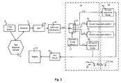
- Fig. 1 illustrates an X-ray analytical system according to the present disclosure, the system typically being used for chemical composition analysis.
- the system comprises a portable X-ray analytical instrument (not shown), an X-ray source 8 emitting X-rays, a test material sample 4, a detector 2, an analog to digital converter (ADC) 12, a spectrum constructor 34, an on-board data processing unit 10, an off-board data processing unit 11, and a display 19.
- the X-ray analytical system of Fig. 1 has various operation modes, optionally including an on-board operation mode 28, a remote operation mode 46, a first shared operation mode 54 and further optionally a second shared operation mode 64.
- On-board data processing unit 10 includes an operator mode selector 17 acting on a logical mode switch 25. Data from spectrum constructor 34 is passed to mode switch 25 via data path S-6. Mode switch 25 directs the data to the one selected operation mode 28, 46, 54 or 64 via the corresponding data path S-1, S-2, S-3 or S-4.
- the portable instrument performs a measurement cycle by exposing test material sample 4 to the output of excitation source 8 and detecting the resulting response with detector 2.
- the output signal of detector 2 is provided to ADC 12, the output of which is sent to spectrum constructor 34, which is a fast processor such as a Field Programmable Gate Array (FPGA) programmed to produce a spectrum from the data acquired during the measurement.
- spectrum constructor 34 which is a fast processor such as a Field Programmable Gate Array (FPGA) programmed to produce a spectrum from the data acquired during the measurement.
- FPGA Field Programmable Gate Array
- processing of the output from spectrum constructor 34 is accomplished either by on-board operation mode 28, or by remote operation mode 46, or by first shared operation mode 54, or by second shared operation mode 64.
- Complex and computationally intensive algorithms are required to derive the chemistry of test material sample 4 from the spectrum created by spectrum constructor 34.
- Steps in deriving the chemistry of test material sample 4 may include application of calibration data for the particular portable instrument being used, application of algorithms to correct for the effect of the sample matrix on the elemental data in the spectrum, or comparison of processed elemental data with known material compositions to identify the material of the test material sample 4. As disclosed in the various embodiments of the present invention, depending on operator selection, all these steps may be performed on-board the portable instrument, or they may all be performed remotely, or the steps may be shared in various ways between the portable instrument and the remote computing capability.
- a two-way data transmission system 20 transmitting data between on-board data processing unit 10 and off-board data processing unit 11.
- the data transmission system comprises a pair of transceivers 20a and 20b, which may receive and transmit data wirelessly or via a physical data connection.
- Two-way data transmission system 20 enables exchange of information between on-board data processing unit 10 and off-board data processing unit 11 by means of a standard wireless interface, such as WLAN or Bluetooth, or by means of a physical data connection, which may consist of a cable with a standard data transfer interface, such as USB, Ethernet or RS232.
- a standard wireless interface such as WLAN or Bluetooth
- a physical data connection which may consist of a cable with a standard data transfer interface, such as USB, Ethernet or RS232.
- signals exchanged between on-board data processing unit 10 and off-board data processing unit 11 can pass through a network router, a smart phone, or other intermediary device present in the communication path, and such intermediary devices are within the scope of the present disclosure.
- one of the most important novel aspects of the present disclosure is to utilize a means of logical mode selection, such as switch 25, to allow the selection among at least two operational modes, each having different ways of splitting the task of spectrum processing and conversion to chemistry between a handheld X-ray analytical instrument and a remote computer.
- a means of logical mode selection such as switch 25, to allow the selection among at least two operational modes, each having different ways of splitting the task of spectrum processing and conversion to chemistry between a handheld X-ray analytical instrument and a remote computer.
- Another novel aspect of the present disclosure is to allow operators to determine the selection mode based on the factors of inspection setup, i.e., the available data speed of data transmission system 20, the required resolution and accuracy of the analysis and the required speed of the measurement cycle.
- XRF X-ray fluorescence
- a measurement cycle of the portable instrument ends when the instrument receives and displays the calculated chemical composition of test material sample 4.
- the measurement cycle is preferably completed in less than one second; however, users may set a longer time if they wish to obtain a more accurate chemistry result.
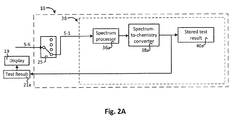
- on-board operation mode 28 when on-board operation mode 28 is selected, spectrum processing and conversion to chemistry are all performed by on-board data processing unit 10, as further shown in Fig. 2A , in which on-board data processing unit 10 has no wireless or other remote data connections.
- remote operation mode 46 spectrum processing and conversion to chemistry are all performed by off-board data processing unit 11, as further shown in Fig. 2B .
- shared processing modules 54 or 64 are selected, spectrum processing and conversion to chemistry can be shared in various ways between on-board data processing unit 10 and off-board data processing unit 11. Examples of such sharing are further shown in Figs. 2C and 2D .
- off-board data processing unit 11 represents all possible remotely accessed computing facilities, commercially available or proprietary to a specific party. It should also be appreciated that off-board data processing unit 11 may be a stand-alone computer or may be part of the Cloud computing network, and such alternation is also within the scope of the present disclosure.
- Fig. 2A shows the on-board operation mode 28 in more detail.
- spectrum data from selected data path S-1 enters on-board operation mode 28.
- the data is processed by spectrum processor 36a and converted to chemistry by spectrum-to-chemistry converter 38a.
- the chemistry result is stored as stored chemistry result 40a and/or sent as test result 21a to be shown on the on-board display 19. It should be noted that when mode switch 25 is set to select on-board operation mode 28, the instrument is effectively a conventional XRF handheld instrument with all data processing completed on-board.
- Fig. 2B illustrates an alternative operation mode 46, which is included in both an on-board data processing unit 10 and an off-board data processing unit 11.
- spectrum data from selected data path S-2 enters remote operation mode 46, and is transmitted to off-board data processing unit 11 by means of data transmission system 20.
- a received spectrum 50b is processed by a remote spectrum processor 36b and converted to chemistry by a remote spectrum-to-chemistry converter 38b.
- the chemistry result may be stored remotely at stored chemistry result 40b and/or sent as test result 21b to the on-board display 19 via sent test result 42b and data transmission system 20.
- Fig. 2C illustrates a first method of sharing data processing, showing a shared operation mode 54 which is included in both an on-board data processing unit 10 and an off-board data processing unit 11.
- spectrum data from selected data path S-3 enters shared operation mode 54.
- the data is processed by on-board spectrum processor 36c, and then transmitted to off-board data processing unit 11 by means of data transmission system 20.
- a received processed spectrum 50c is converted to chemistry by a remote spectrum-to-chemistry converter 38c.
- the chemistry result may be stored remotely at stored chemistry result 40c and/or sent as test result 21c to the on-board display 19 via sent test result 42c and data transmission system 20.
- Fig. 2D illustrates a second method of sharing data processing, showing a shared operation mode 64, which is included in both an on-board data processing unit 10 and an off-board data processing unit 11.
- spectrum data from selected data path S-4 enters shared operation mode 64.
- Data is partially processed by on-board partial spectrum processor1 36d, and then transmitted to off-board data processing unit 11 by means of data transmission system 20.
- Data from a received partially processed spectrum 50d is passed to partial spectrum processor2 36e where spectrum processing is completed.
- the processed spectrum is then converted to chemistry by a remote spectrum-to-chemistry converter 38d.
- the chemistry result may be stored remotely at stored chemistry result 40d and/or sent as test result 21d to the on-board display 19 via sent test result 42d and data transmission system 20.
- spectrum processors 36a, 36b, 36c, 36d, and 36e preferably use different algorithms for processing, with some requiring less and some requiring more computing power, yielding results of less or more accuracy, respectively.
- on-board spectrum processors such as 36a, 36c and 36d have algorithms yielding less accuracy while requiring less computing power.
- Remote spectrum processors such as 36b and 36e have algorithms yielding more accuracy while requiring more computing power.
- corresponding spectrum-to-chemistry converters 38a, 38b, 38c, and 38d are also preferably configured to use different algorithms with some requiring less and some requiring more computing power, yielding results of less or more accuracy, respectively.
- on-board spectrum converters such as 38a have algorithms yielding less accuracy while requiring less computing power.
- Remote spectrum converters such as 38b, 38c and 38d have algorithms yielding more accuracy while requiring more computing power.
- spectrum processors 36a, 36b, 36c, 36d, and 36e, and corresponding spectrum-to-chemistry converters 38a, 38b, 38c, and 38d are depicted as separate functional blocks in Figs. 2A ⁇ 2D .
- each spectrum processor and its corresponding converter can be within the same or separate integrated circuit. Both of these embodiments are within the scope of the present disclosure.
- Fig. 3A is a flow chart which describes an initialization process 14, comprising steps of setting up the portable instrument to operate with remote communication capability.
- step 600 both the portable instrument and the remote computer are initialized.
- step 602 the portable instrument verifies its communication link with off-board data processing unit 11.
- step 604 the portable instrument's parameters and settings are sent to off-board data processing unit 11, and in step 606 the portable instrument is ready to perform measurements with both on-board and remote data analysis capability.
- Fig. 3B which should be viewed in conjunction with Fig. 2B , is a flow chart describing the steps of performing remote spectrum processing and chemistry conversion with remote operation mode 46.
- the portable instrument performs a measurement on test material sample 4, and in step 702 it sends the resulting spectrum to off-board data processing unit 11.
- the remote computer performs processing on the spectrum, and in step 706, the remote computer applies chemistry conversion algorithms to the spectrum.
- the remote computer sends the results back to the portable instrument, and in step 710, the portable instrument displays the chemistry information of test material sample 4.
- Fig. 3C which should be viewed in conjunction with Fig. 2C , is a flow chart describing the steps of a first embodiment of performing shared spectrum processing and chemistry conversion with shared operation mode 54.
- the portable instrument performs a measurement on test material sample 4, and in step 802 it performs on-board processing of the resulting spectrum.
- the portable instrument sends the processed spectrum to off-board data processing unit 11.
- the remote computer applies chemistry conversion algorithms to the spectrum.
- the remote computer sends the results back to the portable instrument, and in step 810, the portable instrument displays the chemistry information of test material sample 4.
- Fig. 3D which should be viewed in conjunction with Fig. 2D , is a flow chart describing the steps of a second embodiment of performing shared spectrum processing and chemistry conversion with shared operation mode 64.
- the portable instrument performs a measurement on test material sample 4, and in step 902 it performs partial on-board processing of the resulting spectrum.
- the portable instrument sends the partially processed spectrum to off-board data processing unit 11.
- the remote computer completes processing of the spectrum, and in step 906 the remote computer applies chemistry conversion algorithms to the processed spectrum.
- the remote computer sends the results back to the portable instrument, and in step 910, the portable instrument displays the chemistry information of test material sample 4.
Landscapes
- Physics & Mathematics (AREA)
- Health & Medical Sciences (AREA)
- Life Sciences & Earth Sciences (AREA)
- Chemical & Material Sciences (AREA)
- Analytical Chemistry (AREA)
- Biochemistry (AREA)
- General Health & Medical Sciences (AREA)
- General Physics & Mathematics (AREA)
- Immunology (AREA)
- Pathology (AREA)
- Spectroscopy & Molecular Physics (AREA)
- Analysing Materials By The Use Of Radiation (AREA)
Abstract
Description
- The present disclosure relates to portable x-ray fluorescence (XRF) analytical inspection instruments, and more particularly to an instrument system which measures the elemental composition (henceforth referred to as 'chemistry') of a test sample, and which is operable by selectively transmitting measured spectrum data to a remotely located computer for remote computation of the chemistry. The chemistry result is subsequently transmitted back to the portable instrument for display to the user in real time.
- Conventional portable XRF analytical instruments consist of an emitter which emits an excitation, a sensor which senses response signals emanating from a test material sample, and a spectrum constructor which constructs a spectrum of the intensity vs energy or wavelength of the response signals. The spectrum is converted to the sample's chemistry by a series of computationally intensive algorithms, and then rendered on the display of the portable instrument.
- In the case of an energy dispersive XRF device, the spectrum is a histogram of the energy levels sensed by the X-ray detector during the measurement process. In the case of optical sensor-based instruments, such as Laser Induced Breakdown Spectroscopy (LIBS) and Near Infrared Spectroscopy (NIRS), among others, the spectrum is a histogram of the wavelengths of the electromagnetic energy emanating from the test material sample.
- The primary purpose for using such analytical instrument technologies is to quickly and accurately determine the chemistry of a material test sample in order to classify it qualitatively or quantitatively. A qualitative classification indicates that one or more atomic elements of interest are present in a material test sample. A quantitative classification indicates the concentration of one or more atomic elements of interest that are present in a material test sample. For optimal inspection productivity, and to reduce measurement variability, it is important to minimize the time interval between the start of a measurement cycle and its end when the chemistry result is displayed. This has been a long standing challenge for designers of analytical portable instruments.
- Presently, all of the signal processing required to derive chemistry information from a raw spectrum is performed entirely within the portable instrument. This is hereafter referred to as "on-board" processing. In on-board processing, the signal processing performance is not optimal due to the practical constraints associated with a portable instrument, such as power consumption and electronics packaging space. Accordingly, the limits placed on the speed and amount of signal processing required for producing a highly accurate chemistry result cause conventional instruments to be far from optimal as compared to what could be achieved if such constraints did not exist.
- It is the general object of the present disclosure to overcome the problems associated with background art by introducing an instrument system with a substantially improved measurement chemistry result that can be displayed to the user of a portable analytical instrument in real time.
- More specifically, the general object of the present disclosure is to improve the speed, precision and accuracy of the chemistry calculation performed on the spectrum data acquired by the portable instrument from a test sample material. This is achieved by transmitting the spectrum data to a high performance remote computer in order to perform the intensive signal processing required to determine the sample's chemistry with a high degree of fidelity, and then returning the result to the portable instrument to be displayed in real time without any noticeable delay. (i.e. The complete measurement cycle should be less than about one second). This method of transmitting data to a high performance remote computer is hereafter referred to as "remote" or "off-board" processing, the two terms being used interchangeably.
- The foregoing and other objects of the present disclosure may be realized with a portable instrument, a remote computing capability, a communication interface that can be wireless or have a physical cable connection, and a means to apply spectrum processing and/or chemistry conversion outside of the portable instrument. The remote computing capability may include connection to a specific computer or connection via internet to distributed computation capability hereafter referred to as "the Cloud".
- In accordance with various embodiments of the invention, disclosed is an arrangement of an analog to digital converter (ADC), a spectrum constructor, an on-board data processing unit having two or more operation modes, and having physical or wireless data connections with one or more remote computers, including computers located in the Cloud. The on-board data processing unit is thereby able to take advantage of the increased processing power of remote computers during measurement of the chemistry of a material sample. The primary object of the present disclosure is to outsource the hardware limitations of a portable instrument to a computer system of greater processing power.
-
-
Fig. 1 is a schematic view of the preferred embodiment according to the present disclosure. -
Fig. 2A is a schematic view of the embodiment with regular on-board data processing selected according to the present disclosure. -
Fig. 2B is a schematic view of the embodiment wherein the remote computer performs all of the spectrum processing and conversion to chemistry according to the present disclosure. -
Fig. 2C is a schematic view of the embodiment where the portable instrument performs the spectrum processing and the remote computer performs the conversion to chemistry according to the present disclosure. -
Fig. 2D is a schematic view of the embodiment where the portable instrument performs part of the spectrum processing and the remote computer completes the spectrum processing and then performs the conversion to chemistry according to the present disclosure. -
Fig. 3A is a flow chart showing initialization of the communication between the portable instrument and a remote computer. -
Fig. 3B is a flow chart of the embodiment where the remote computer performs all of the spectrum processing and conversion to chemistry. -
Fig. 3C is a flow chart of the embodiment where the portable instrument performs the spectrum processing and the remote computer performs the conversion to chemistry. -
Fig. 3D is a flow chart of the embodiment where the portable instrument performs part of the spectrum processing and the remote computer completes the spectrum processing and then performs the conversion to chemistry. -
Fig. 1 illustrates an X-ray analytical system according to the present disclosure, the system typically being used for chemical composition analysis. The system comprises a portable X-ray analytical instrument (not shown), an X-ray source 8 emitting X-rays, atest material sample 4, adetector 2, an analog to digital converter (ADC) 12, aspectrum constructor 34, an on-boarddata processing unit 10, an off-boarddata processing unit 11, and adisplay 19. The X-ray analytical system ofFig. 1 has various operation modes, optionally including an on-board operation mode 28, aremote operation mode 46, a first sharedoperation mode 54 and further optionally a second sharedoperation mode 64. On-boarddata processing unit 10 includes anoperator mode selector 17 acting on alogical mode switch 25. Data fromspectrum constructor 34 is passed tomode switch 25 via data path S-6.Mode switch 25 directs the data to the one selectedoperation mode - The portable instrument performs a measurement cycle by exposing
test material sample 4 to the output of excitation source 8 and detecting the resulting response withdetector 2. The output signal ofdetector 2 is provided toADC 12, the output of which is sent tospectrum constructor 34, which is a fast processor such as a Field Programmable Gate Array (FPGA) programmed to produce a spectrum from the data acquired during the measurement. Depending onoperator mode selection 17, processing of the output fromspectrum constructor 34 is accomplished either by on-board operation mode 28, or byremote operation mode 46, or by first sharedoperation mode 54, or by second sharedoperation mode 64. Complex and computationally intensive algorithms, well known to those skilled in the art, are required to derive the chemistry oftest material sample 4 from the spectrum created byspectrum constructor 34. Steps in deriving the chemistry oftest material sample 4 may include application of calibration data for the particular portable instrument being used, application of algorithms to correct for the effect of the sample matrix on the elemental data in the spectrum, or comparison of processed elemental data with known material compositions to identify the material of thetest material sample 4. As disclosed in the various embodiments of the present invention, depending on operator selection, all these steps may be performed on-board the portable instrument, or they may all be performed remotely, or the steps may be shared in various ways between the portable instrument and the remote computing capability. - Also shown in
Fig. 1 is a two-waydata transmission system 20 transmitting data between on-boarddata processing unit 10 and off-boarddata processing unit 11. The data transmission system comprises a pair oftransceivers data transmission system 20 enables exchange of information between on-boarddata processing unit 10 and off-boarddata processing unit 11 by means of a standard wireless interface, such as WLAN or Bluetooth, or by means of a physical data connection, which may consist of a cable with a standard data transfer interface, such as USB, Ethernet or RS232. When a description of an embodiment refers to either the wireless or the cable connection, it is intended to denote that the other may be used if necessary or desired. - It should be noted that the signals exchanged between on-board
data processing unit 10 and off-boarddata processing unit 11 can pass through a network router, a smart phone, or other intermediary device present in the communication path, and such intermediary devices are within the scope of the present disclosure. - It should be herein noted that one of the most important novel aspects of the present disclosure is to utilize a means of logical mode selection, such as
switch 25, to allow the selection among at least two operational modes, each having different ways of splitting the task of spectrum processing and conversion to chemistry between a handheld X-ray analytical instrument and a remote computer. - Another novel aspect of the present disclosure is to allow operators to determine the selection mode based on the factors of inspection setup, i.e., the available data speed of
data transmission system 20, the required resolution and accuracy of the analysis and the required speed of the measurement cycle. - Although the teachings in the present disclosure apply to any portable X-ray or optical analytical instrument used for non-destructive testing (NDT), the exemplary embodiment described herein is an X-ray fluorescence (XRF) instrument.
- A measurement cycle of the portable instrument ends when the instrument receives and displays the calculated chemical composition of
test material sample 4. The measurement cycle is preferably completed in less than one second; however, users may set a longer time if they wish to obtain a more accurate chemistry result. - Referring again to
Fig. 1 , when on-board operation mode 28 is selected, spectrum processing and conversion to chemistry are all performed by on-boarddata processing unit 10, as further shown inFig. 2A , in which on-boarddata processing unit 10 has no wireless or other remote data connections. Whenremote operation mode 46 is selected, spectrum processing and conversion to chemistry are all performed by off-boarddata processing unit 11, as further shown inFig. 2B . When sharedprocessing modules data processing unit 10 and off-boarddata processing unit 11. Examples of such sharing are further shown inFigs. 2C and2D . - It should be noted that off-board
data processing unit 11 represents all possible remotely accessed computing facilities, commercially available or proprietary to a specific party. It should also be appreciated that off-boarddata processing unit 11 may be a stand-alone computer or may be part of the Cloud computing network, and such alternation is also within the scope of the present disclosure. -
Fig. 2A shows the on-board operation mode 28 in more detail. Directed bymode switch 25, spectrum data from selected data path S-1 enters on-board operation mode 28. The data is processed by spectrum processor 36a and converted to chemistry by spectrum-to-chemistry converter 38a. The chemistry result is stored as storedchemistry result 40a and/or sent as test result 21a to be shown on the on-board display 19. It should be noted that whenmode switch 25 is set to select on-board operation mode 28, the instrument is effectively a conventional XRF handheld instrument with all data processing completed on-board. - Reference is now made to
Fig. 2B , which illustrates analternative operation mode 46, which is included in both an on-boarddata processing unit 10 and an off-boarddata processing unit 11. Directed bymode switch 25, spectrum data from selected data path S-2 entersremote operation mode 46, and is transmitted to off-boarddata processing unit 11 by means ofdata transmission system 20. A received spectrum 50b is processed by aremote spectrum processor 36b and converted to chemistry by a remote spectrum-to-chemistry converter 38b. The chemistry result may be stored remotely at storedchemistry result 40b and/or sent astest result 21b to the on-board display 19 via senttest result 42b anddata transmission system 20. -
Fig. 2C illustrates a first method of sharing data processing, showing a sharedoperation mode 54 which is included in both an on-boarddata processing unit 10 and an off-boarddata processing unit 11. Directed bymode switch 25, spectrum data from selected data path S-3 enters sharedoperation mode 54. The data is processed by on-board spectrum processor 36c, and then transmitted to off-boarddata processing unit 11 by means ofdata transmission system 20. A received processedspectrum 50c is converted to chemistry by a remote spectrum-to-chemistry converter 38c. The chemistry result may be stored remotely at storedchemistry result 40c and/or sent astest result 21c to the on-board display 19 via senttest result 42c anddata transmission system 20. -
Fig. 2D illustrates a second method of sharing data processing, showing a sharedoperation mode 64, which is included in both an on-boarddata processing unit 10 and an off-boarddata processing unit 11. Directed bymode switch 25, spectrum data from selected data path S-4 enters sharedoperation mode 64. Data is partially processed by on-boardpartial spectrum processor1 36d, and then transmitted to off-boarddata processing unit 11 by means ofdata transmission system 20. Data from a received partially processedspectrum 50d is passed to partial spectrum processor2 36e where spectrum processing is completed. The processed spectrum is then converted to chemistry by a remote spectrum-to-chemistry converter 38d. The chemistry result may be stored remotely at storedchemistry result 40d and/or sent astest result 21d to the on-board display 19 via sent test result 42d anddata transmission system 20. - It should be noted that
spectrum processors chemistry converters - In addition,
spectrum processors chemistry converters Figs. 2A ∼ 2D . However, each spectrum processor and its corresponding converter can be within the same or separate integrated circuit. Both of these embodiments are within the scope of the present disclosure. -
Fig. 3A is a flow chart which describes aninitialization process 14, comprising steps of setting up the portable instrument to operate with remote communication capability. Instep 600, both the portable instrument and the remote computer are initialized. Instep 602, the portable instrument verifies its communication link with off-boarddata processing unit 11. Instep 604, the portable instrument's parameters and settings are sent to off-boarddata processing unit 11, and instep 606 the portable instrument is ready to perform measurements with both on-board and remote data analysis capability. -
Fig. 3B , which should be viewed in conjunction withFig. 2B , is a flow chart describing the steps of performing remote spectrum processing and chemistry conversion withremote operation mode 46. Instep 700, the portable instrument performs a measurement ontest material sample 4, and instep 702 it sends the resulting spectrum to off-boarddata processing unit 11. Instep 704, the remote computer performs processing on the spectrum, and instep 706, the remote computer applies chemistry conversion algorithms to the spectrum. Instep 708, the remote computer sends the results back to the portable instrument, and instep 710, the portable instrument displays the chemistry information oftest material sample 4. -
Fig. 3C , which should be viewed in conjunction withFig. 2C , is a flow chart describing the steps of a first embodiment of performing shared spectrum processing and chemistry conversion with sharedoperation mode 54. Instep 800, the portable instrument performs a measurement ontest material sample 4, and instep 802 it performs on-board processing of the resulting spectrum. Instep 804 the portable instrument sends the processed spectrum to off-boarddata processing unit 11. Instep 806, the remote computer applies chemistry conversion algorithms to the spectrum. Instep 808, the remote computer sends the results back to the portable instrument, and instep 810, the portable instrument displays the chemistry information oftest material sample 4. -
Fig. 3D , which should be viewed in conjunction withFig. 2D , is a flow chart describing the steps of a second embodiment of performing shared spectrum processing and chemistry conversion with sharedoperation mode 64. Instep 900, the portable instrument performs a measurement ontest material sample 4, and instep 902 it performs partial on-board processing of the resulting spectrum. Instep 904 the portable instrument sends the partially processed spectrum to off-boarddata processing unit 11. Instep 905 the remote computer completes processing of the spectrum, and instep 906 the remote computer applies chemistry conversion algorithms to the processed spectrum. Instep 908, the remote computer sends the results back to the portable instrument, and instep 910, the portable instrument displays the chemistry information oftest material sample 4. - Although the present invention has been described in relation to particular embodiments thereof, many other variations and modifications and other uses will become apparent to those skilled in the art. It is preferred, therefore, that the present invention not be limited by the specific disclosure herein.
Claims (20)
- An X-ray analytical system for testing and analyzing chemical composition and/or atomic structure of a sample during a testing session, the system comprising a portable X-ray analytical instrument for testing and analyzing chemical composition and/or atomic structure of a sample, and an off-board data processing unit situated off-board separately from the portable instrument, wherein the instrument comprises,
an X-ray source configured to emit a beam of X-rays onto a sample,
a detector configured to detect received X-rays returned from the sample,
a spectrum constructor constructing a raw spectrum from the received X-rays,
an on-board data processing unit, wherein the on-board data processing unit and the off-board data processing unit are configured in unison to complete at least two processing tasks, which collectively process an entire processing task of processing the raw spectrum to produce a test result for display on the instrument,
a display configured to display the test result, and,
wherein the on-board processing unit further comprises,an operator mode selector connected to and instructing a mode switch to switch between at least two operation modes, wherein each of the at least two operation modes defines how the entire processing task is distributed between the at least two processing tasks. - The X-ray analytical system of claim 1, wherein the X-ray analytical system further includes a data transmission system comprising a first transceiver on the on-board data processing unit, and a second transceiver on the off-board data processing unit, the data transmission system thereby allowing two-way communication between the off-board data processing unit and the on-board data processing unit.
- The X-ray analytical system of claim 2, wherein the data transmission system is configured to be a wireless transmission system, and the first transceiver is a first wireless transceiver and the second transceiver is a second wireless transceiver.
- The X-ray analytical system of claim 1, wherein the off-board data processing unit is not integrally packaged together with the portable instrument and is at any distance from the portable instrument.
- The X-ray analytical system of claim 1, wherein the detector produces electronic analog pulses, one pulse for each X-ray received, wherein the amplitude of each pulse is proportional to the energy of the corresponding X-ray.
- The X-ray analytical system of claim 5, wherein the instrument further comprises an analog to digital converter converting the analog pulses to digital data.
- The X-ray analytical system of claim 5, wherein the spectrum constructor is a fast spectrum constructor which constructs a spectrum of the number of pulses received within each X-ray energy range.
- The X-ray analytical system of claim 2, wherein the entire processing task further includes spectrum processing, spectrum to chemistry converting and test result forming.
- The X-ray analytical system of claim 8, wherein the at least two processing tasks includes an on-board processing task being performed by the on-board processing unit, and an off-board processing task being performed by the off-board processing unit.
- The X-ray analytical system of claim 9, wherein the operator mode selector instructs the mode switch to switch to an operation mode in which the on-board processing task includes all of the at least two processing tasks and the off-board processing task is nil.
- The X-ray analytical system of claim 10, wherein the data transmission system is not activated during the testing session.
- The X-ray analytical system of claim 9, wherein the operator mode selector instructs the mode switch to switch to an operation mode in which all of the off-board processing task includes all of the at least two processing tasks and the on-board processing task is nil.
- The X-ray analytical system of claim 12, wherein the data transmission system transmits the raw spectrum from the on-board data processing unit to the off-board data processing unit, and the data transmission system subsequently transmits at least part of the testing result from the off-board data processing unit to the on-board data processing unit for displaying the test result on the instrument.
- The X-ray analytical system of claim 9, wherein the operator mode selector instructs the mode switch to switch to an operation mode in which the on-board processing task is the spectrum processing, and the off-board processing task is the spectrum to chemistry converting and test result forming.
- The X-ray analytical system of claim 14, wherein the data transmission system transmits a data set from the spectrum processing from the on-board data processing unit to the off-board data processing unit, and the data transmission system subsequently transmits at least part of the testing result from the off-board data processing unit to the on-board data processing unit for displaying the test result on the instrument.
- The X-ray analytical system of claim 15, wherein the data transmission system is configured so that the first transceiver and the second transceiver establish data communication with each other prior to the testing session.
- The X-ray analytical system of claim 9, wherein the operator mode selector instructs the mode switch to switch to an operation mode in which the on-board processing task includes a first part of the spectrum processing, and the off-board processing task includes a second part of the spectrum processing, and wherein the first and the second parts of the spectrum processing collectively constitute the entire spectrum processing.
- The X-ray analytical system of claim 17, wherein the off-board processing task includes conversion to chemistry.
- The X-ray analytical system of claim 18, wherein the data transmission system transmits a data set from the first part of the spectrum processing from the on-board data processing unit to the off-board data processing unit, and the data transmission system subsequently transmits at least part of the testing result from the off-board data processing unit to the on-board data processing unit for displaying the test result on the instrument.
- The X-ray analytical system of claim 19, wherein the data transmission system is configured so that the first transceiver and the second transceiver establish data communication with each other prior to the testing session.
Applications Claiming Priority (1)
| Application Number | Priority Date | Filing Date | Title |
|---|---|---|---|
| US14/865,827 US9933375B2 (en) | 2015-09-25 | 2015-09-25 | XRF/XRD system with dynamic management of multiple data processing units |
Publications (2)
| Publication Number | Publication Date |
|---|---|
| EP3147655A1 true EP3147655A1 (en) | 2017-03-29 |
| EP3147655B1 EP3147655B1 (en) | 2024-11-06 |
Family
ID=56985482
Family Applications (1)
| Application Number | Title | Priority Date | Filing Date |
|---|---|---|---|
| EP16189718.6A Active EP3147655B1 (en) | 2015-09-25 | 2016-09-20 | An xrf/xrd system with dynamic management of multiple data processing units |
Country Status (3)
| Country | Link |
|---|---|
| US (1) | US9933375B2 (en) |
| EP (1) | EP3147655B1 (en) |
| CN (1) | CN107014844B (en) |
Cited By (2)
| Publication number | Priority date | Publication date | Assignee | Title |
|---|---|---|---|---|
| EP3393105A1 (en) * | 2017-04-21 | 2018-10-24 | Olympus Scientific Solutions Americas Inc. | Data storage localization selection for industrial inspection |
| CN114935581A (en) * | 2022-07-26 | 2022-08-23 | 深圳市科誉仪器有限公司 | Automatic change intelligent integral type X ray fluorescence spectrum appearance |
Families Citing this family (2)
| Publication number | Priority date | Publication date | Assignee | Title |
|---|---|---|---|---|
| US10365158B2 (en) * | 2011-10-25 | 2019-07-30 | Daylight Solutions, Inc. | Low-noise spectroscopic imaging system |
| CN115943302B (en) | 2020-03-13 | 2026-04-28 | 贝克休斯油田作业有限责任公司 | Surface logging using rock cuttings-based rock physics analysis |
Citations (4)
| Publication number | Priority date | Publication date | Assignee | Title |
|---|---|---|---|---|
| US20040113773A1 (en) * | 2002-12-11 | 2004-06-17 | General Electric Company | Method and apparatus for internet enabled, wireless remote sensor measurement |
| US20060279732A1 (en) * | 2005-05-24 | 2006-12-14 | Wang Sean X | Spectroscopic sensor on mobile phone |
| US20090195776A1 (en) * | 2007-07-18 | 2009-08-06 | Roger David Durst | Handheld spectrometer including wireless capabilities |
| US20130187052A1 (en) * | 2012-01-19 | 2013-07-25 | Princeton Gamma Tech. Instruments Inc. | Dual range digital nuclear spectrometer |
Family Cites Families (51)
| Publication number | Priority date | Publication date | Assignee | Title |
|---|---|---|---|---|
| US5299138A (en) * | 1991-08-09 | 1994-03-29 | The United States Of America As Represented By The Secretary Of Commerce | Desk top spectrum analyzer |
| JP2002022846A (en) * | 2000-07-05 | 2002-01-23 | Seiko Instruments Inc | Energy dispersive X-ray analyzer |
| CN100433039C (en) * | 2005-08-03 | 2008-11-12 | 正品科技(北京)有限公司 | Mark method adopting chemical elements, device thereof and chemical elements marking |
| US7587025B2 (en) * | 2007-01-23 | 2009-09-08 | Sii Nanotechnology Inc. | X-ray analysis apparatus and X-ray analysis method |
| US7916834B2 (en) * | 2007-02-12 | 2011-03-29 | Thermo Niton Analyzers Llc | Small spot X-ray fluorescence (XRF) analyzer |
| US7430273B2 (en) * | 2007-02-23 | 2008-09-30 | Thermo Fisher Scientific Inc. | Instrument having X-ray fluorescence and spark emission spectroscopy analysis capabilities |
| US7623625B2 (en) * | 2007-04-11 | 2009-11-24 | Searete Llc | Compton scattered X-ray visualization, imaging, or information provider with scattering event locating |
| JP5235447B2 (en) * | 2008-02-22 | 2013-07-10 | 株式会社日立ハイテクサイエンス | X-ray analyzer and X-ray analysis method |
| JP5307504B2 (en) * | 2008-08-22 | 2013-10-02 | 株式会社日立ハイテクサイエンス | X-ray analyzer and X-ray analysis method |
| JP5269521B2 (en) * | 2008-08-22 | 2013-08-21 | 株式会社日立ハイテクサイエンス | X-ray analyzer and X-ray analysis method |
| WO2010054018A1 (en) * | 2008-11-04 | 2010-05-14 | Thermo Niton Analyzers Llc | Dynamic modification of shaping time in x-ray detectors |
| JP2012512394A (en) * | 2008-12-12 | 2012-05-31 | サーモ ニトン アナライザーズ リミテッド ライアビリティ カンパニー | Automatic sum peak suppression in X-ray fluorescence analyzers |
| US8155268B2 (en) * | 2009-04-23 | 2012-04-10 | Thermo Niton Analyzers Llc | Rapid screening for lead concentration compliance by X-ray fluorescence (XRF) analysis |
| EP2425234B1 (en) * | 2009-04-30 | 2019-10-23 | Thermo Scientific Portable Analytical Instruments Inc. | Localization of an element of interest by xrf analysis of different inspection volumes |
| JP5461924B2 (en) * | 2009-08-28 | 2014-04-02 | 株式会社日立ハイテクサイエンス | X-ray analyzer and X-ray analysis method |
| US20110292376A1 (en) * | 2010-05-26 | 2011-12-01 | Kukushkin Igor V | Apparatus and method for detecting raman and photoluminescence spectra of a substance |
| JP5481321B2 (en) * | 2010-08-31 | 2014-04-23 | 株式会社日立ハイテクサイエンス | X-ray fluorescence analyzer and X-ray fluorescence analysis method |
| CN102128842B (en) * | 2010-11-18 | 2012-09-12 | 李华 | Portable double-resource X-ray parallel three-dimensional industrial CT (computed tomography) system and control method thereof |
| JP5684612B2 (en) * | 2011-03-09 | 2015-03-18 | 株式会社日立ハイテクサイエンス | X-ray analyzer |
| US8612580B2 (en) * | 2011-05-31 | 2013-12-17 | Microsoft Corporation | Distributed computing framework |
| US8787523B2 (en) * | 2011-07-01 | 2014-07-22 | Olympus Ndt, Inc. | X-ray analysis apparatus with radiation monitoring feature |
| EP2790016B1 (en) * | 2011-12-09 | 2017-07-19 | HORIBA, Ltd. | X-ray analysis device |
| EP2790015B1 (en) * | 2011-12-09 | 2018-03-28 | HORIBA, Ltd. | X-ray analysis device |
| US8515009B1 (en) * | 2012-02-03 | 2013-08-20 | Thermo Niton Analyzers Llc | Metal authenticity testing of an object using radiation |
| CN103294728B (en) * | 2012-03-05 | 2017-08-08 | 阿里巴巴集团控股有限公司 | A kind of data processing method and system |
| CN103376251A (en) * | 2012-04-19 | 2013-10-30 | 上海迪亚凯特生物医药科技有限公司 | Portable Raman spectrum measuring device and system for quickly detecting article |
| US8982338B2 (en) * | 2012-05-31 | 2015-03-17 | Thermo Scientific Portable Analytical Instruments Inc. | Sample analysis |
| US9182363B2 (en) * | 2012-11-16 | 2015-11-10 | Olympus Ndt, Inc. | Instrument and method of measuring the concentration of a target element in a multi-layer thin coating |
| JP6082634B2 (en) * | 2013-03-27 | 2017-02-15 | 株式会社日立ハイテクサイエンス | X-ray fluorescence analyzer |
| JP6081260B2 (en) * | 2013-03-28 | 2017-02-15 | 株式会社日立ハイテクサイエンス | X-ray fluorescence analyzer |
| CN104215623B (en) * | 2013-05-31 | 2018-09-25 | 欧普图斯(苏州)光学纳米科技有限公司 | Laser Raman spectroscopy intelligence discrimination method and system towards conglomerate detection |
| US9778213B2 (en) * | 2013-08-19 | 2017-10-03 | Kla-Tencor Corporation | Metrology tool with combined XRF and SAXS capabilities |
| US9449781B2 (en) * | 2013-12-05 | 2016-09-20 | Sigray, Inc. | X-ray illuminators with high flux and high flux density |
| US9570265B1 (en) * | 2013-12-05 | 2017-02-14 | Sigray, Inc. | X-ray fluorescence system with high flux and high flux density |
| US9448190B2 (en) * | 2014-06-06 | 2016-09-20 | Sigray, Inc. | High brightness X-ray absorption spectroscopy system |
| US9310324B2 (en) * | 2013-09-24 | 2016-04-12 | Oxford Instruments Analytical Oy | X-ray fluorescence analyzer with safety features |
| WO2015101992A2 (en) * | 2014-01-03 | 2015-07-09 | Verifood, Ltd. | Spectrometry systems, methods, and applications |
| US9594036B2 (en) * | 2014-02-28 | 2017-03-14 | Sigray, Inc. | X-ray surface analysis and measurement apparatus |
| JP2015184039A (en) * | 2014-03-20 | 2015-10-22 | 株式会社日立ハイテクサイエンス | X-ray analyzer |
| US9188552B2 (en) * | 2014-03-26 | 2015-11-17 | Jeol Ltd. | X-ray spectrometer and sample analyzer |
| CN105092624B (en) * | 2014-05-20 | 2019-08-27 | 株式会社堀场制作所 | Analytical equipment and bearing calibration |
| WO2016002357A1 (en) * | 2014-07-01 | 2016-01-07 | 株式会社リガク | X-ray fluorescence analysis device and method |
| JP5874109B2 (en) * | 2014-07-23 | 2016-03-02 | 株式会社リガク | X-ray detection signal processing apparatus and X-ray analysis apparatus using the same |
| US9683953B2 (en) * | 2014-08-20 | 2017-06-20 | Moxtek, Inc. | XRF analyzer communication |
| JP6305280B2 (en) * | 2014-08-28 | 2018-04-04 | 株式会社日立ハイテクサイエンス | X-ray fluorescence analyzer and sample display method thereof |
| JP6346036B2 (en) * | 2014-09-09 | 2018-06-20 | 株式会社日立ハイテクサイエンス | X-ray fluorescence analyzer and method for adjusting measurement position thereof |
| JP6002890B2 (en) * | 2014-09-18 | 2016-10-05 | 株式会社リガク | X-ray analyzer |
| US9829448B2 (en) * | 2014-10-30 | 2017-11-28 | Bruker Jv Israel Ltd. | Measurement of small features using XRF |
| JP2016099308A (en) * | 2014-11-26 | 2016-05-30 | 株式会社日立ハイテクサイエンス | X-ray fluorescence analyzer and X-ray fluorescence analysis method |
| JP6305327B2 (en) * | 2014-12-04 | 2018-04-04 | 株式会社日立ハイテクサイエンス | X-ray fluorescence analyzer |
| US9739730B2 (en) * | 2015-03-03 | 2017-08-22 | Panalytical B.V. | Quantitative X-ray analysis—multi optical path instrument |
-
2015
- 2015-09-25 US US14/865,827 patent/US9933375B2/en active Active
-
2016
- 2016-09-20 EP EP16189718.6A patent/EP3147655B1/en active Active
- 2016-09-23 CN CN201610847547.4A patent/CN107014844B/en active Active
Patent Citations (4)
| Publication number | Priority date | Publication date | Assignee | Title |
|---|---|---|---|---|
| US20040113773A1 (en) * | 2002-12-11 | 2004-06-17 | General Electric Company | Method and apparatus for internet enabled, wireless remote sensor measurement |
| US20060279732A1 (en) * | 2005-05-24 | 2006-12-14 | Wang Sean X | Spectroscopic sensor on mobile phone |
| US20090195776A1 (en) * | 2007-07-18 | 2009-08-06 | Roger David Durst | Handheld spectrometer including wireless capabilities |
| US20130187052A1 (en) * | 2012-01-19 | 2013-07-25 | Princeton Gamma Tech. Instruments Inc. | Dual range digital nuclear spectrometer |
Cited By (6)
| Publication number | Priority date | Publication date | Assignee | Title |
|---|---|---|---|---|
| EP3393105A1 (en) * | 2017-04-21 | 2018-10-24 | Olympus Scientific Solutions Americas Inc. | Data storage localization selection for industrial inspection |
| US10785303B2 (en) | 2017-04-21 | 2020-09-22 | Olympus America Inc. | Data center selection for communication with an industrial testing device |
| US11223684B2 (en) | 2017-04-21 | 2022-01-11 | Olympus America Inc. | Data center selection for communication with an industrial testing device |
| US11683376B2 (en) | 2017-04-21 | 2023-06-20 | Olympus America Inc. | Data center selection for communication with an industrial testing device |
| CN114935581A (en) * | 2022-07-26 | 2022-08-23 | 深圳市科誉仪器有限公司 | Automatic change intelligent integral type X ray fluorescence spectrum appearance |
| CN114935581B (en) * | 2022-07-26 | 2023-01-17 | 深圳市科誉仪器有限公司 | Automatic change intelligent integral type X ray fluorescence spectrum appearance |
Also Published As
| Publication number | Publication date |
|---|---|
| CN107014844A (en) | 2017-08-04 |
| CN107014844B (en) | 2020-04-21 |
| US9933375B2 (en) | 2018-04-03 |
| EP3147655B1 (en) | 2024-11-06 |
| US20170089847A1 (en) | 2017-03-30 |
Similar Documents
| Publication | Publication Date | Title |
|---|---|---|
| EP3147655B1 (en) | An xrf/xrd system with dynamic management of multiple data processing units | |
| JP4951502B2 (en) | Measuring head for spectral analysis and method for recalibration thereof | |
| KR101790355B1 (en) | X-ray analyzing apparatus | |
| US9590122B2 (en) | Fish eye lens analyzer | |
| JP4614001B2 (en) | Three-dimensional quantitative method using transmitted X-ray | |
| US7889335B2 (en) | Handheld spectrometer including wireless capabilities | |
| JP2015526135A5 (en) | ||
| US10168142B2 (en) | Optical characteristic measuring apparatus and optical characteristic measuring method | |
| EP3951366A1 (en) | Product inspection method and product inspection device | |
| JP2016080429A (en) | Spectral measurement device | |
| KR20230022897A (en) | Cross-validation based calibration of a spectroscopic model | |
| NL2014335B1 (en) | An infrared sensor unit, a method and a computer program product. | |
| CN110514620A (en) | Spectral method of detection and system based on portable near infrared spectrometer | |
| JP2011038846A (en) | Interference film thickness gauge | |
| JP2016206060A (en) | Spectrometer and spectroscopic method | |
| US11366013B2 (en) | Method of obtaining quantum efficiency distribution, method of displaying quantum efficiency distribution, program for obtaining quantum efficiency distribution, program for displaying quantum efficiency distribution, fluorescence spectrophotometer, and display device | |
| JP6061031B2 (en) | Spectroscopic analysis system and method | |
| CN109342370B (en) | Detection method, related device and storage medium | |
| CN120418638A (en) | Spectroscopic analysis device and spectroscopic analysis method | |
| JP2018091691A (en) | X-ray fluorescence spectrometer | |
| JP5927081B2 (en) | Spectroscopic measurement method | |
| JP2012021794A5 (en) | Optical coherence tomography acquisition method, optical coherence tomography acquisition device, and optical coherence tomography acquisition system | |
| JP4517111B2 (en) | Brain function measuring device, brain function measuring method, and brain function measuring program | |
| WO2015125311A1 (en) | Spectroscopic measurement method | |
| JP2003329430A (en) | Inspection object thickness measurement method |
Legal Events
| Date | Code | Title | Description |
|---|---|---|---|
| PUAI | Public reference made under article 153(3) epc to a published international application that has entered the european phase |
Free format text: ORIGINAL CODE: 0009012 |
|
| STAA | Information on the status of an ep patent application or granted ep patent |
Free format text: STATUS: THE APPLICATION HAS BEEN PUBLISHED |
|
| AK | Designated contracting states |
Kind code of ref document: A1 Designated state(s): AL AT BE BG CH CY CZ DE DK EE ES FI FR GB GR HR HU IE IS IT LI LT LU LV MC MK MT NL NO PL PT RO RS SE SI SK SM TR |
|
| AX | Request for extension of the european patent |
Extension state: BA ME |
|
| STAA | Information on the status of an ep patent application or granted ep patent |
Free format text: STATUS: REQUEST FOR EXAMINATION WAS MADE |
|
| 17P | Request for examination filed |
Effective date: 20170929 |
|
| RBV | Designated contracting states (corrected) |
Designated state(s): AL AT BE BG CH CY CZ DE DK EE ES FI FR GB GR HR HU IE IS IT LI LT LU LV MC MK MT NL NO PL PT RO RS SE SI SK SM TR |
|
| STAA | Information on the status of an ep patent application or granted ep patent |
Free format text: STATUS: EXAMINATION IS IN PROGRESS |
|
| 17Q | First examination report despatched |
Effective date: 20201012 |
|
| REG | Reference to a national code |
Ref country code: DE Free format text: PREVIOUS MAIN CLASS: G01N0023223000 Ref country code: DE Ref legal event code: R079 Ref document number: 602016090107 Country of ref document: DE Free format text: PREVIOUS MAIN CLASS: G01N0023223000 Ipc: G01N0023220900 |
|
| GRAP | Despatch of communication of intention to grant a patent |
Free format text: ORIGINAL CODE: EPIDOSNIGR1 |
|
| STAA | Information on the status of an ep patent application or granted ep patent |
Free format text: STATUS: GRANT OF PATENT IS INTENDED |
|
| RIC1 | Information provided on ipc code assigned before grant |
Ipc: G01N 23/223 20060101ALI20231115BHEP Ipc: G01N 23/2209 20180101AFI20231115BHEP |
|
| INTG | Intention to grant announced |
Effective date: 20231129 |
|
| GRAJ | Information related to disapproval of communication of intention to grant by the applicant or resumption of examination proceedings by the epo deleted |
Free format text: ORIGINAL CODE: EPIDOSDIGR1 |
|
| STAA | Information on the status of an ep patent application or granted ep patent |
Free format text: STATUS: EXAMINATION IS IN PROGRESS |
|
| GRAP | Despatch of communication of intention to grant a patent |
Free format text: ORIGINAL CODE: EPIDOSNIGR1 |
|
| STAA | Information on the status of an ep patent application or granted ep patent |
Free format text: STATUS: GRANT OF PATENT IS INTENDED |
|
| INTC | Intention to grant announced (deleted) | ||
| INTG | Intention to grant announced |
Effective date: 20240408 |
|
| GRAS | Grant fee paid |
Free format text: ORIGINAL CODE: EPIDOSNIGR3 |
|
| RAP1 | Party data changed (applicant data changed or rights of an application transferred) |
Owner name: EVIDENT SCIENTIFIC, INC. |
|
| GRAA | (expected) grant |
Free format text: ORIGINAL CODE: 0009210 |
|
| STAA | Information on the status of an ep patent application or granted ep patent |
Free format text: STATUS: THE PATENT HAS BEEN GRANTED |
|
| AK | Designated contracting states |
Kind code of ref document: B1 Designated state(s): AL AT BE BG CH CY CZ DE DK EE ES FI FR GB GR HR HU IE IS IT LI LT LU LV MC MK MT NL NO PL PT RO RS SE SI SK SM TR |
|
| REG | Reference to a national code |
Ref country code: GB Ref legal event code: FG4D |
|
| REG | Reference to a national code |
Ref country code: CH Ref legal event code: EP |
|
| REG | Reference to a national code |
Ref country code: DE Ref legal event code: R096 Ref document number: 602016090107 Country of ref document: DE |
|
| REG | Reference to a national code |
Ref country code: IE Ref legal event code: FG4D |
|
| REG | Reference to a national code |
Ref country code: DE Ref legal event code: R082 Ref document number: 602016090107 Country of ref document: DE Representative=s name: STOLMAR & PARTNER PATENTANWAELTE PARTG MBB, DE |
|
| REG | Reference to a national code |
Ref country code: LT Ref legal event code: MG9D |
|
| REG | Reference to a national code |
Ref country code: NL Ref legal event code: MP Effective date: 20241106 |
|
| PG25 | Lapsed in a contracting state [announced via postgrant information from national office to epo] |
Ref country code: HR Free format text: LAPSE BECAUSE OF FAILURE TO SUBMIT A TRANSLATION OF THE DESCRIPTION OR TO PAY THE FEE WITHIN THE PRESCRIBED TIME-LIMIT Effective date: 20241106 Ref country code: IS Free format text: LAPSE BECAUSE OF FAILURE TO SUBMIT A TRANSLATION OF THE DESCRIPTION OR TO PAY THE FEE WITHIN THE PRESCRIBED TIME-LIMIT Effective date: 20250306 Ref country code: PT Free format text: LAPSE BECAUSE OF FAILURE TO SUBMIT A TRANSLATION OF THE DESCRIPTION OR TO PAY THE FEE WITHIN THE PRESCRIBED TIME-LIMIT Effective date: 20250306 |
|
| PG25 | Lapsed in a contracting state [announced via postgrant information from national office to epo] |
Ref country code: FI Free format text: LAPSE BECAUSE OF FAILURE TO SUBMIT A TRANSLATION OF THE DESCRIPTION OR TO PAY THE FEE WITHIN THE PRESCRIBED TIME-LIMIT Effective date: 20241106 Ref country code: NL Free format text: LAPSE BECAUSE OF FAILURE TO SUBMIT A TRANSLATION OF THE DESCRIPTION OR TO PAY THE FEE WITHIN THE PRESCRIBED TIME-LIMIT Effective date: 20241106 |
|
| REG | Reference to a national code |
Ref country code: AT Ref legal event code: MK05 Ref document number: 1739861 Country of ref document: AT Kind code of ref document: T Effective date: 20241106 |
|
| PG25 | Lapsed in a contracting state [announced via postgrant information from national office to epo] |
Ref country code: BG Free format text: LAPSE BECAUSE OF FAILURE TO SUBMIT A TRANSLATION OF THE DESCRIPTION OR TO PAY THE FEE WITHIN THE PRESCRIBED TIME-LIMIT Effective date: 20241106 |
|
| PG25 | Lapsed in a contracting state [announced via postgrant information from national office to epo] |
Ref country code: ES Free format text: LAPSE BECAUSE OF FAILURE TO SUBMIT A TRANSLATION OF THE DESCRIPTION OR TO PAY THE FEE WITHIN THE PRESCRIBED TIME-LIMIT Effective date: 20241106 |
|
| PG25 | Lapsed in a contracting state [announced via postgrant information from national office to epo] |
Ref country code: NO Free format text: LAPSE BECAUSE OF FAILURE TO SUBMIT A TRANSLATION OF THE DESCRIPTION OR TO PAY THE FEE WITHIN THE PRESCRIBED TIME-LIMIT Effective date: 20250206 |
|
| PG25 | Lapsed in a contracting state [announced via postgrant information from national office to epo] |
Ref country code: AT Free format text: LAPSE BECAUSE OF FAILURE TO SUBMIT A TRANSLATION OF THE DESCRIPTION OR TO PAY THE FEE WITHIN THE PRESCRIBED TIME-LIMIT Effective date: 20241106 Ref country code: LV Free format text: LAPSE BECAUSE OF FAILURE TO SUBMIT A TRANSLATION OF THE DESCRIPTION OR TO PAY THE FEE WITHIN THE PRESCRIBED TIME-LIMIT Effective date: 20241106 Ref country code: GR Free format text: LAPSE BECAUSE OF FAILURE TO SUBMIT A TRANSLATION OF THE DESCRIPTION OR TO PAY THE FEE WITHIN THE PRESCRIBED TIME-LIMIT Effective date: 20250207 |
|
| PG25 | Lapsed in a contracting state [announced via postgrant information from national office to epo] |
Ref country code: PL Free format text: LAPSE BECAUSE OF FAILURE TO SUBMIT A TRANSLATION OF THE DESCRIPTION OR TO PAY THE FEE WITHIN THE PRESCRIBED TIME-LIMIT Effective date: 20241106 |
|
| PG25 | Lapsed in a contracting state [announced via postgrant information from national office to epo] |
Ref country code: RS Free format text: LAPSE BECAUSE OF FAILURE TO SUBMIT A TRANSLATION OF THE DESCRIPTION OR TO PAY THE FEE WITHIN THE PRESCRIBED TIME-LIMIT Effective date: 20250206 |
|
| PG25 | Lapsed in a contracting state [announced via postgrant information from national office to epo] |
Ref country code: SM Free format text: LAPSE BECAUSE OF FAILURE TO SUBMIT A TRANSLATION OF THE DESCRIPTION OR TO PAY THE FEE WITHIN THE PRESCRIBED TIME-LIMIT Effective date: 20241106 |
|
| PG25 | Lapsed in a contracting state [announced via postgrant information from national office to epo] |
Ref country code: DK Free format text: LAPSE BECAUSE OF FAILURE TO SUBMIT A TRANSLATION OF THE DESCRIPTION OR TO PAY THE FEE WITHIN THE PRESCRIBED TIME-LIMIT Effective date: 20241106 |
|
| PG25 | Lapsed in a contracting state [announced via postgrant information from national office to epo] |
Ref country code: EE Free format text: LAPSE BECAUSE OF FAILURE TO SUBMIT A TRANSLATION OF THE DESCRIPTION OR TO PAY THE FEE WITHIN THE PRESCRIBED TIME-LIMIT Effective date: 20241106 |
|
| PG25 | Lapsed in a contracting state [announced via postgrant information from national office to epo] |
Ref country code: RO Free format text: LAPSE BECAUSE OF FAILURE TO SUBMIT A TRANSLATION OF THE DESCRIPTION OR TO PAY THE FEE WITHIN THE PRESCRIBED TIME-LIMIT Effective date: 20241106 |
|
| PG25 | Lapsed in a contracting state [announced via postgrant information from national office to epo] |
Ref country code: SK Free format text: LAPSE BECAUSE OF FAILURE TO SUBMIT A TRANSLATION OF THE DESCRIPTION OR TO PAY THE FEE WITHIN THE PRESCRIBED TIME-LIMIT Effective date: 20241106 |
|
| PG25 | Lapsed in a contracting state [announced via postgrant information from national office to epo] |
Ref country code: CZ Free format text: LAPSE BECAUSE OF FAILURE TO SUBMIT A TRANSLATION OF THE DESCRIPTION OR TO PAY THE FEE WITHIN THE PRESCRIBED TIME-LIMIT Effective date: 20241106 |
|
| PG25 | Lapsed in a contracting state [announced via postgrant information from national office to epo] |
Ref country code: IT Free format text: LAPSE BECAUSE OF FAILURE TO SUBMIT A TRANSLATION OF THE DESCRIPTION OR TO PAY THE FEE WITHIN THE PRESCRIBED TIME-LIMIT Effective date: 20241106 |
|
| REG | Reference to a national code |
Ref country code: DE Ref legal event code: R097 Ref document number: 602016090107 Country of ref document: DE |
|
| PG25 | Lapsed in a contracting state [announced via postgrant information from national office to epo] |
Ref country code: SE Free format text: LAPSE BECAUSE OF FAILURE TO SUBMIT A TRANSLATION OF THE DESCRIPTION OR TO PAY THE FEE WITHIN THE PRESCRIBED TIME-LIMIT Effective date: 20241106 |
|
| PLBE | No opposition filed within time limit |
Free format text: ORIGINAL CODE: 0009261 |
|
| STAA | Information on the status of an ep patent application or granted ep patent |
Free format text: STATUS: NO OPPOSITION FILED WITHIN TIME LIMIT |
|
| PGFP | Annual fee paid to national office [announced via postgrant information from national office to epo] |
Ref country code: DE Payment date: 20250929 Year of fee payment: 10 |
|
| 26N | No opposition filed |
Effective date: 20250807 |
|
| PGFP | Annual fee paid to national office [announced via postgrant information from national office to epo] |
Ref country code: GB Payment date: 20250929 Year of fee payment: 10 |
|
| PGFP | Annual fee paid to national office [announced via postgrant information from national office to epo] |
Ref country code: FR Payment date: 20250925 Year of fee payment: 10 |
|
| REG | Reference to a national code |
Ref country code: CH Ref legal event code: H13 Free format text: ST27 STATUS EVENT CODE: U-0-0-H10-H13 (AS PROVIDED BY THE NATIONAL OFFICE) Effective date: 20260425 |