EP3147567A1 - Single skin combustor with heat transfer enhancement - Google Patents
Single skin combustor with heat transfer enhancement Download PDFInfo
- Publication number
- EP3147567A1 EP3147567A1 EP16191216.7A EP16191216A EP3147567A1 EP 3147567 A1 EP3147567 A1 EP 3147567A1 EP 16191216 A EP16191216 A EP 16191216A EP 3147567 A1 EP3147567 A1 EP 3147567A1
- Authority
- EP
- European Patent Office
- Prior art keywords
- cooling
- single skin
- combustor
- liner
- air
- Prior art date
- Legal status (The legal status is an assumption and is not a legal conclusion. Google has not performed a legal analysis and makes no representation as to the accuracy of the status listed.)
- Granted
Links
Images


Classifications
-
- F—MECHANICAL ENGINEERING; LIGHTING; HEATING; WEAPONS; BLASTING
- F23—COMBUSTION APPARATUS; COMBUSTION PROCESSES
- F23R—GENERATING COMBUSTION PRODUCTS OF HIGH PRESSURE OR HIGH VELOCITY, e.g. GAS-TURBINE COMBUSTION CHAMBERS
- F23R3/00—Continuous combustion chambers using liquid or gaseous fuel
- F23R3/02—Continuous combustion chambers using liquid or gaseous fuel characterised by the air-flow or gas-flow configuration
- F23R3/04—Air inlet arrangements
-
- F—MECHANICAL ENGINEERING; LIGHTING; HEATING; WEAPONS; BLASTING
- F23—COMBUSTION APPARATUS; COMBUSTION PROCESSES
- F23R—GENERATING COMBUSTION PRODUCTS OF HIGH PRESSURE OR HIGH VELOCITY, e.g. GAS-TURBINE COMBUSTION CHAMBERS
- F23R3/00—Continuous combustion chambers using liquid or gaseous fuel
- F23R3/002—Wall structures
-
- F—MECHANICAL ENGINEERING; LIGHTING; HEATING; WEAPONS; BLASTING
- F23—COMBUSTION APPARATUS; COMBUSTION PROCESSES
- F23R—GENERATING COMBUSTION PRODUCTS OF HIGH PRESSURE OR HIGH VELOCITY, e.g. GAS-TURBINE COMBUSTION CHAMBERS
- F23R3/00—Continuous combustion chambers using liquid or gaseous fuel
- F23R3/005—Combined with pressure or heat exchangers
-
- F—MECHANICAL ENGINEERING; LIGHTING; HEATING; WEAPONS; BLASTING
- F23—COMBUSTION APPARATUS; COMBUSTION PROCESSES
- F23R—GENERATING COMBUSTION PRODUCTS OF HIGH PRESSURE OR HIGH VELOCITY, e.g. GAS-TURBINE COMBUSTION CHAMBERS
- F23R3/00—Continuous combustion chambers using liquid or gaseous fuel
- F23R3/02—Continuous combustion chambers using liquid or gaseous fuel characterised by the air-flow or gas-flow configuration
- F23R3/04—Air inlet arrangements
- F23R3/06—Arrangement of apertures along the flame tube
-
- F—MECHANICAL ENGINEERING; LIGHTING; HEATING; WEAPONS; BLASTING
- F23—COMBUSTION APPARATUS; COMBUSTION PROCESSES
- F23R—GENERATING COMBUSTION PRODUCTS OF HIGH PRESSURE OR HIGH VELOCITY, e.g. GAS-TURBINE COMBUSTION CHAMBERS
- F23R2900/00—Special features of, or arrangements for continuous combustion chambers; Combustion processes therefor
- F23R2900/03042—Film cooled combustion chamber walls or domes
-
- F—MECHANICAL ENGINEERING; LIGHTING; HEATING; WEAPONS; BLASTING
- F23—COMBUSTION APPARATUS; COMBUSTION PROCESSES
- F23R—GENERATING COMBUSTION PRODUCTS OF HIGH PRESSURE OR HIGH VELOCITY, e.g. GAS-TURBINE COMBUSTION CHAMBERS
- F23R2900/00—Special features of, or arrangements for continuous combustion chambers; Combustion processes therefor
- F23R2900/03045—Convection cooled combustion chamber walls provided with turbolators or means for creating turbulences to increase cooling
-
- Y—GENERAL TAGGING OF NEW TECHNOLOGICAL DEVELOPMENTS; GENERAL TAGGING OF CROSS-SECTIONAL TECHNOLOGIES SPANNING OVER SEVERAL SECTIONS OF THE IPC; TECHNICAL SUBJECTS COVERED BY FORMER USPC CROSS-REFERENCE ART COLLECTIONS [XRACs] AND DIGESTS
- Y02—TECHNOLOGIES OR APPLICATIONS FOR MITIGATION OR ADAPTATION AGAINST CLIMATE CHANGE
- Y02T—CLIMATE CHANGE MITIGATION TECHNOLOGIES RELATED TO TRANSPORTATION
- Y02T50/00—Aeronautics or air transport
- Y02T50/60—Efficient propulsion technologies, e.g. for aircraft
Definitions
- the application relates generally to gas turbine engines and, more particularly, to single skin combustor liner cooling.
- a single skin design Compared to double or multi-skinned combustors, a single skin design has the potential to be lighter in weight and hence lower in cost.
- current effusion cooled liner designs are limited in efficiency due to manufacturing constraints such as hole size and angle. Therefore, without increasing cooling air consumption, additional heat removal is a challenge.
- the total amount of air available for combustor wall cooling within the gas turbine thermodynamic cycle can be limited, especially where rich-burn combustion is sought. Therefore, it is a challenge to optimize the combustor wall cooling while still meeting the durability requirements of single skin combustors.
- a single skin combustor for a gas turbine engine having an engine casing
- the single skin combustor comprising: a single skin liner defining a combustion chamber, the single skin liner having an inner surface exposed to the combustion chamber and an outer surface exposed to air in a plenum circumscribed by the engine casing, the outer surface of the single skin liner being an outermost surface of the combustor, cooling holes extending through the single skin liner, and cooling protrusions projecting integrally from the outer surface of the single skin liner, the cooling protrusions being interspersed between the cooling holes.
- a method of cooling a single skin liner of a combustor of a gas turbine engine having an engine casing defining a plenum around the single skin liner comprising: 1) providing a first usage of cooling air in the plenum by causing the cooling air to flow through cooling protuberances extending from an outer surface of the single skin liner, the cooling protuberances projecting into the plenum, 2) providing a second usage of the cooling air by flowing the cooling air through cooling holes defined in the single skin liner, the cooling holes fluidly linking a combustion chamber of the combustor to the plenum, and 3) providing a third usage of the cooling air by using the cooling air exiting the cooling holes to form a film of cooling air over an inner surface of the single skin liner.
- a gas turbine engine comprising a gas generator case, a combustor disposed within the gas generator case, the combustor comprising a single skin liner circumscribing a combustion chamber, the single skin liner and the gas generator case defining therebetween a plenum, the single skin liner having an outer surface exposed to cooling air in the plenum and an inner surface exposed to combustion gases in the combustion chamber, cooling holes defined in the single skin liner, the cooling holes fluidly liking the plenum to the combustion chamber, and cooling protuberances integrally projecting from the outer surface of the single skin liner into the plenum.
- Fig. 1 illustrates a gas turbine engine 10 of a type preferably provided for use in subsonic flight, generally comprising in serial flow communication a fan 12 through which ambient air is propelled, a compressor 14 for pressurizing the air, a combustor 16 in which the compressed air is mixed with fuel and ignited for generating an annular stream of hot combustion gases, and a turbine section 18 for extracting energy from the combustion gases.
- the combustor 16 is a single skin combustor. That is the combustor 16 has a single skin liner.
- the single skin liner comprises a radially inner liner 20a and a radially outer liner 20b concentrically disposed relative to a central axis of the engine and defining therebetween an annular combustion chamber 22.
- the radially inner and radially outer liners 20a, 20b may each be made from a single sheet of metal with through holes defined therein for cooling purposes.
- double or multi-sheet liners have gaps of cooling air made by sandwiching two or more sheets of metal or mounting heat shields on the inner surface of a liner to maintain some form of air gap through which cooling air may be guided to cool the innermost skin of the liner.
- a plurality of circumferentially spaced-apart nozzles are provided at the dome end of the combustor 16 to inject a fuel/air mixture into the combustion chamber 22.
- Igniters are provided along the upstream end portion of the combustion chamber 22 downstream of the tip of the nozzles 28 in order to initiate combustion of the fuel/air mixture delivered into the combustion chamber 22.
- the inner and outer liners 20a, 20b define a primary zone of the combustion chamber 22 at the upstream end thereof, where the fuel/air mixture provided by the fuel nozzles is ignited.
- the primary zone is generally understood as the region in which the fuel is burn and has the highest flame temperature within the combustor 16.
- the combustor 16 also has a secondary zone, which is the region characterized by first additional air jets to quench the hot product generated by the primary zone; and a dilution zone corresponding to the region where second additional jets quench the hot product and profile the hot product prior to discharge to the turbine section 18.
- the combustor 16 is mounted in a plenum 17 circumscribed by an engine casing 26 (e.g. a gas generator case).
- the plenum 17 extends from the single skin liner of the combustor 16 to the engine casing 26.
- the single skin liner is an outermost surface of the combustor 16.
- the single skin liner is free of coverage in the plenum 17 (it is not surrounded/covered by any flow guiding structure or sleeve to form an air gap like in a double skin design).
- the plenum 17 is supplied with compressor bleed air from the compressor 14. As illustrated in Fig. 2 , the compressor bleed air is discharged from a compressor exit tube 21 into the plenum 17.
- FIG. 2 schematically illustrates the flow field in the plenum 17. It can be appreciated that the air is allowed to flow according to various flow patterns and in different directions within the plenum 17. The flow is not guided or constricted to flow in an organized manner within the plenum 17. This is different from a cooling flow passing through a gap between two adjacent walls of a multi-skinned designed combustor. According to such double or multi-skinned arrangements, the air flowing over the innermost liner is constrained to flow in predetermined directions.
- a plurality of cooling holes 30 are defined in the inner and outer single skin liners 20a, 20b for allowing air in the plenum 17 to flow through the liners 20a, 20b, thereby picking up heat therefrom, and to then form a protective film of cooling air over the combustion facing surface 32 of the liners 20a, 20b.
- heat transfer augmentation protrusions such as cooling fins 34
- the fins 34 enable the air in the plenum 17 to pick up more heat prior to entering the combustion chamber 22 through the cooling holes 30. Accordingly, cooling efficiency can be improved without increasing cooling air consumption.
- the fins 34 provide for an additional use of the same cooling air.
- the fins 34 may be provided in the form of free-standing pin fins integrally projecting from the outer surface 36 of the radially inner and outer single skin liners 20a, 20b into the plenum 17.
- the fins 34 may be integrally formed on the outer surface 36 of the liner by means of additive manufacturing or other suitable manufacturing processes.
- cold side fins 34 can be obtained as an extension of a base metal of the single skin liner by laying down successive layers of the base metal onto the outer surface of a perforated sheet metal substrate.
- the cooling protrusions may adopt various shapes and configurations.
- the cooling protrusions could take the form of cylindrical pin fins 34.
- the protrusions 34a could have a tapering profile as for instance shown in Fig. 3 .
- the cooling protrusions could also take the form of dimples 34b ( Fig. 4a ) or trusses 34c ( Fig. 4b ).
- the protrusions could also have a rectangular geometry and be angularly disposed on the outer surface of the liner with respect to the incoming flow of cooling air. Other shapes and configurations are contemplated as well.
- the fins 34, 34a, 34b, 34c are positioned strategically with respect to the cooling hole pattern.
- at least some of the fins 34a could be individually positioned directly behind (immediately downstream) corresponding cooling holes 30 to capture air, thereby creating an extra pressure right in front of the cooling holes 30 to more effectively drive the air through the cooling holes 30 into the combustion chamber 22.
- the fins 34a could be inclined in the upstream direction relative to the air flow (depicted by flow arrow "a ") in the plenum by an angle (9) generally corresponding to the inclination angle of the associated neighboring cooling hole 30.
- the fins 34a extend from the rim of the associated hole 30 on a downstream side thereof relative to the cooling air flow direction. From Fig. 3 , it can be appreciated that the front or upstream face of the fin 34a extends generally in continuity to the downstream or back wall surface of the hole 30. However, it is understood that the fins 34, 34a, 34b and 34c could be otherwise interspersed between the cooling holes 30.
- the fins 34, 34a, 34b and 34c could be distributed on a partial surface of the single skin liner or over a full surface thereof.
- the fins 34, 34a, 34b and 34c are distributed so as to provide for a uniform temperature distribution all around the combustor liner 20a, 20b.
- the density of fins can be greater in hot spot regions and less in cooler regions of the combustor 16.
- a greater concentration of fins 34, 34a, 34b and 34c can be provided in certain regions of the combustor 16 where it is desirable to limit the quantity of cooling air flowing into the combustor because the cooling air may have a detrimental effect on the overall combustion process.
- This may be achieved by reducing the density of cooling holes 30 in the primary zone and correspondingly increasing the density of cooling fins 34, 34a, 34b and 34c in this same primary zone so as to compensate for the reduced number of cooling holes.
- the fins 34, 34a, 34b, 34c can be of uniform or non-uniform height. Also, it is understood that a combination of different shapes of fins can be provided on the cold outer surface 36 of a same single skin liner 20a, 20b. In fact, various combinations of fin sizes, distributions and dimensions are possible.
- the cold side fins 34, 34a, 34b, 34c enable the cooling air to be used more than once prior to entering the combustion chamber 22 on a single skin design. Indeed, the compressor bleed air directed into the plenum 17 first flow over the outer surface 36 of the inner and outer liners 20a, 20b through the field of pin fins 34, 34a, 34b, 34c. As the air flows through the fins 34, 34a, 34b, 34c, it picks up heats from the liners 20a, 20b. The air has a second opportunity to cool the liners 20a, 20b by flowing through the cooling holes 30. Indeed, as the air flows through the cooling holes 30, it cools the liners 20a, 20b by in-hole heat transfer.
- the air flows over the inner or hot combustion facing surface 32 of the liners 20a, 20b, thereby providing for the formation of a protective cooling film thereover. Accordingly, with the addition of the fins on the cold side of the liner, the air has (3) opportunities to cool down the liner. Multiple usage of the same cooling air provides for improved cooling efficiency. In this way, single skin combustors may be used in high temperature applications where double skin combustor designs would have typically been retained. Also, since the fins are located on the cold side of the combustor liner, they are not exposed to the hot combustion gasses and are, thus, less subject to erosion over time. This provides for a more robust design. Also the cold side fins 34, 34a, 34b, 34c can be applied in conjunction with existing cooling schemes on single skin liners.
Landscapes
- Engineering & Computer Science (AREA)
- Chemical & Material Sciences (AREA)
- Combustion & Propulsion (AREA)
- Mechanical Engineering (AREA)
- General Engineering & Computer Science (AREA)
- Gas Burners (AREA)
- Turbine Rotor Nozzle Sealing (AREA)
Abstract
Description
- The application relates generally to gas turbine engines and, more particularly, to single skin combustor liner cooling.
- Compared to double or multi-skinned combustors, a single skin design has the potential to be lighter in weight and hence lower in cost. However, current effusion cooled liner designs are limited in efficiency due to manufacturing constraints such as hole size and angle. Therefore, without increasing cooling air consumption, additional heat removal is a challenge. In aviation gas turbine engines, it is desirable that the amount of air supplied for cooling combustor walls be minimized in order not to negatively affect the overall performances of the engine. This poses challenges to meeting the durability requirements of single skin combustor walls, because the reduction in combustion wall cooling air may lead to unwanted material oxidation, thermal mechanical fatigue and/or thermal wall buckling due to thermal gradients. Particularly in small aero gas turbine engines, the total amount of air available for combustor wall cooling within the gas turbine thermodynamic cycle can be limited, especially where rich-burn combustion is sought. Therefore, it is a challenge to optimize the combustor wall cooling while still meeting the durability requirements of single skin combustors.
- In one aspect, there is provided a single skin combustor for a gas turbine engine having an engine casing, the single skin combustor comprising: a single skin liner defining a combustion chamber, the single skin liner having an inner surface exposed to the combustion chamber and an outer surface exposed to air in a plenum circumscribed by the engine casing, the outer surface of the single skin liner being an outermost surface of the combustor, cooling holes extending through the single skin liner, and cooling protrusions projecting integrally from the outer surface of the single skin liner, the cooling protrusions being interspersed between the cooling holes.
- In another aspect, there is provided a method of cooling a single skin liner of a combustor of a gas turbine engine having an engine casing defining a plenum around the single skin liner, the method comprising: 1) providing a first usage of cooling air in the plenum by causing the cooling air to flow through cooling protuberances extending from an outer surface of the single skin liner, the cooling protuberances projecting into the plenum, 2) providing a second usage of the cooling air by flowing the cooling air through cooling holes defined in the single skin liner, the cooling holes fluidly linking a combustion chamber of the combustor to the plenum, and 3) providing a third usage of the cooling air by using the cooling air exiting the cooling holes to form a film of cooling air over an inner surface of the single skin liner.
- In a still further aspect, which the Applicant expressly reserves the right to claim independently, there is provided a gas turbine engine comprising a gas generator case, a combustor disposed within the gas generator case, the combustor comprising a single skin liner circumscribing a combustion chamber, the single skin liner and the gas generator case defining therebetween a plenum, the single skin liner having an outer surface exposed to cooling air in the plenum and an inner surface exposed to combustion gases in the combustion chamber, cooling holes defined in the single skin liner, the cooling holes fluidly liking the plenum to the combustion chamber, and cooling protuberances integrally projecting from the outer surface of the single skin liner into the plenum.
- Reference is now made to the accompanying figures in which:
-
Fig. 1 is a schematic cross-section of a gas turbine engine; -
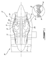
Fig. 2 is a schematic enlarged cross-section view of the combustor of the engine shown inFig. 1 and illustrating a single skin liner with cooling fins on the cold outer side of the liner; -
Fig. 3 is a schematic enlarged cross-section view of non-cylindrically shaped fins on the cold outer side of a single skin combustor liner; -
Figs. 4a and 4b are schematic views illustrating various shapes and configurations that the cooling fins can adopt. -
Fig. 1 illustrates agas turbine engine 10 of a type preferably provided for use in subsonic flight, generally comprising in serial flow communication afan 12 through which ambient air is propelled, acompressor 14 for pressurizing the air, acombustor 16 in which the compressed air is mixed with fuel and ignited for generating an annular stream of hot combustion gases, and aturbine section 18 for extracting energy from the combustion gases. - The
combustor 16 is a single skin combustor. That is thecombustor 16 has a single skin liner. According to one embodiment, the single skin liner comprises a radiallyinner liner 20a and a radiallyouter liner 20b concentrically disposed relative to a central axis of the engine and defining therebetween anannular combustion chamber 22. The radially inner and radiallyouter liners - A plurality of circumferentially spaced-apart nozzles (only two being shown at 28) are provided at the dome end of the
combustor 16 to inject a fuel/air mixture into thecombustion chamber 22. Igniters (not shown) are provided along the upstream end portion of thecombustion chamber 22 downstream of the tip of thenozzles 28 in order to initiate combustion of the fuel/air mixture delivered into thecombustion chamber 22. The inner andouter liners combustion chamber 22 at the upstream end thereof, where the fuel/air mixture provided by the fuel nozzles is ignited. The primary zone is generally understood as the region in which the fuel is burn and has the highest flame temperature within thecombustor 16. Thecombustor 16 also has a secondary zone, which is the region characterized by first additional air jets to quench the hot product generated by the primary zone; and a dilution zone corresponding to the region where second additional jets quench the hot product and profile the hot product prior to discharge to theturbine section 18. - The
combustor 16 is mounted in aplenum 17 circumscribed by an engine casing 26 (e.g. a gas generator case). Theplenum 17 extends from the single skin liner of thecombustor 16 to theengine casing 26. In other words, the single skin liner is an outermost surface of thecombustor 16. The single skin liner is free of coverage in the plenum 17 (it is not surrounded/covered by any flow guiding structure or sleeve to form an air gap like in a double skin design). Theplenum 17 is supplied with compressor bleed air from thecompressor 14. As illustrated inFig. 2 , the compressor bleed air is discharged from acompressor exit tube 21 into theplenum 17.Fig. 2 schematically illustrates the flow field in theplenum 17. It can be appreciated that the air is allowed to flow according to various flow patterns and in different directions within theplenum 17. The flow is not guided or constricted to flow in an organized manner within theplenum 17. This is different from a cooling flow passing through a gap between two adjacent walls of a multi-skinned designed combustor. According to such double or multi-skinned arrangements, the air flowing over the innermost liner is constrained to flow in predetermined directions. - As schematically illustrated in
Figs. 1 and2 , a plurality ofcooling holes 30 are defined in the inner and outersingle skin liners plenum 17 to flow through theliners combustion facing surface 32 of theliners - Still referring to
Figs. 1 and2 , heat transfer augmentation protrusions, such ascooling fins 34, are provided on the cold outer surface orback side 36 of the inner andouter liners fins 34 enable the air in theplenum 17 to pick up more heat prior to entering thecombustion chamber 22 through thecooling holes 30. Accordingly, cooling efficiency can be improved without increasing cooling air consumption. Thefins 34 provide for an additional use of the same cooling air. - The
fins 34 may be provided in the form of free-standing pin fins integrally projecting from theouter surface 36 of the radially inner and outersingle skin liners plenum 17. Thefins 34 may be integrally formed on theouter surface 36 of the liner by means of additive manufacturing or other suitable manufacturing processes. According to one embodiment,cold side fins 34 can be obtained as an extension of a base metal of the single skin liner by laying down successive layers of the base metal onto the outer surface of a perforated sheet metal substrate. - As can be appreciated from
Figs. 2 ,3, 4a and 4b , the cooling protrusions may adopt various shapes and configurations. For instance, as shown inFig. 2 , the cooling protrusions could take the form ofcylindrical pin fins 34. Alternatively, theprotrusions 34a could have a tapering profile as for instance shown inFig. 3 . The cooling protrusions could also take the form ofdimples 34b (Fig. 4a ) ortrusses 34c (Fig. 4b ). The protrusions could also have a rectangular geometry and be angularly disposed on the outer surface of the liner with respect to the incoming flow of cooling air. Other shapes and configurations are contemplated as well. - The
fins Fig. 3 in connection with thetapered fins 34a, at least some of thefins 34a could be individually positioned directly behind (immediately downstream) correspondingcooling holes 30 to capture air, thereby creating an extra pressure right in front of thecooling holes 30 to more effectively drive the air through thecooling holes 30 into thecombustion chamber 22. As shown inFig. 3 , thefins 34a could be inclined in the upstream direction relative to the air flow (depicted by flow arrow "a ") in the plenum by an angle (9) generally corresponding to the inclination angle of the associated neighboringcooling hole 30. In the illustrated embodiment, thefins 34a extend from the rim of the associatedhole 30 on a downstream side thereof relative to the cooling air flow direction. FromFig. 3 , it can be appreciated that the front or upstream face of thefin 34a extends generally in continuity to the downstream or back wall surface of thehole 30. However, it is understood that thefins - The
fins fins combustor liner combustor 16. Also, a greater concentration offins combustor 16 where it is desirable to limit the quantity of cooling air flowing into the combustor because the cooling air may have a detrimental effect on the overall combustion process. For instance, in some applications, it might be desirable to cut down on the amount of cooling air directed into the primary zone of thecombustor 16 in order to maintain a rich fuel/air mixture ratio. This may be achieved by reducing the density of cooling holes 30 in the primary zone and correspondingly increasing the density of coolingfins - The
fins outer surface 36 of a samesingle skin liner - The
cold side fins combustion chamber 22 on a single skin design. Indeed, the compressor bleed air directed into theplenum 17 first flow over theouter surface 36 of the inner andouter liners pin fins fins liners liners liners combustion facing surface 32 of theliners cold side fins - The above description is meant to be exemplary only, and one skilled in the art will recognize that changes may be made to the embodiments described without departing from the scope of the invention disclosed. For instance, the same principle could be applied to a combustor can. Any modifications which fall within the scope of the present invention will be apparent to those skilled in the art, in light of a review of this disclosure, and such modifications are intended to fall within the appended claims.
Claims (15)
- A single skin combustor (16) for a gas turbine engine (10) having an engine casing (26), the single skin combustor (16) comprising: a single skin liner (20a, 20b) defining a combustion chamber (22), the single skin liner (20a, 20b) having an inner surface (32) exposed to the combustion chamber (22) and an outer surface (36) exposed to air in a plenum (17) circumscribed by the engine casing (26), the outer surface (36) of the single skin liner (20a, 20b) being an outermost surface of the combustor (16), cooling holes (30) extending through the single skin liner (20a, 20b), and cooling protrusions (34) projecting integrally from the outer surface (36) of the single skin liner (20a, 20b), the cooling protrusions (34) being interspersed between the cooling holes (30).
- The single skin combustor (16) defined in claim 1, wherein the cooling protrusions (34) are an extension of a base metal of the single skin liner (20a, 20b).
- The single skin combustor (16) defined in claim 1 or 2, wherein each cooling protrusion (34) comprises successive layers of sequentially deposit material on a sheet metal base.
- The single skin combustor (16) defined in claim 1, 2 or 3, wherein the cooling protrusions (34) are provided in the form of individually free standing fins (34).
- The single skin combustor (16) defined in any preceding claim, wherein the density of cooling protrusions (34) varies over the outer surface (36) of the single skin liner (20a, 20b), and optionally wherein a higher density of cooling protrusion (34) is provided in a primary zone of the combustor (16) than in a secondary zone thereof.
- The single skin combustor (16) defined in any preceding claim, wherein the cooling protrusions (34) are of non-uniform height.
- The single skin combustor (16) defined in any preceding claim, wherein at least some of the cooling protrusions (34) are disposed immediately downstream corresponding neighboring cooling holes (30).
- The single skin combustor (16) defined in claim 7, wherein the at least some of the cooling protrusions (34) have respective upstream faces extending generally in continuity to a downstream surface of the neighboring cooling holes (30) behind which they are positioned.
- The single skin combustor (16) defined in any preceding claim, wherein at least some of the cooling protrusions (34) and the cooling holes (30) have similar inclination angles.
- The single skin combustor (16) defined in any preceding claim, wherein the cooling protrusions (34) are selected from a group consisting of: fins, pin fins, dimples and truss-shaped fins.
- A gas turbine engine (10) comprising a single skin combustor (16) as defined in any preceding claim.
- The gas turbine engine (10) defined in claim 11, wherein the cooling protrusions (34) are provided in the form of individually free standing fins (34) projecting from a perforated sheet metal substrate, wherein, optionally, the density of fins (34) varies over the outer surface of the single skin liner.
- A method of cooling a single skin liner (20a, 20b) of a combustor (16) of a gas turbine engine (10) having an engine casing (26) defining a plenum (17) around the single skin liner (20a, 20b), the method comprising:providing a first usage of cooling air in the plenum (17) by causing the cooling air to flow through cooling protuberances (34) extending from an outer surface (36) of the single skin liner (20a, 20b), the cooling protuberances (34) projecting into the plenum (17);providing a second usage of the cooling air by flowing the cooling air through cooling holes (30) defined in the single skin liner (20a, 20b), the cooling holes (30) fluidly linking a combustion chamber (22) of the combustor (16) to the plenum (17);and providing a third usage of the cooling air by using the cooling air exiting the cooling holes (30) to form a film of cooling air over an inner surface (32) of the single skin liner (20a, 20b).
- The method defined in claim 13, wherein the cooling air is compressor bleed air, and wherein the method comprises: discharging the compressor bleed air in the plenum (17), the compressor bleed air being free to flow in various directions within the plenum (17).
- The method of claim 13 or 14, comprising locally building up pressure in front of the cooling holes (30), optionally wherein locally building up pressure comprises positioning the cooling fins (34) directly behind the cooling holes (30).
Applications Claiming Priority (1)
| Application Number | Priority Date | Filing Date | Title |
|---|---|---|---|
| US14/867,377 US10260751B2 (en) | 2015-09-28 | 2015-09-28 | Single skin combustor with heat transfer enhancement |
Publications (2)
| Publication Number | Publication Date |
|---|---|
| EP3147567A1 true EP3147567A1 (en) | 2017-03-29 |
| EP3147567B1 EP3147567B1 (en) | 2023-08-09 |
Family
ID=57042681
Family Applications (1)
| Application Number | Title | Priority Date | Filing Date |
|---|---|---|---|
| EP16191216.7A Active EP3147567B1 (en) | 2015-09-28 | 2016-09-28 | Single skin combustor with heat transfer enhancement |
Country Status (3)
| Country | Link |
|---|---|
| US (1) | US10260751B2 (en) |
| EP (1) | EP3147567B1 (en) |
| CA (1) | CA2939289C (en) |
Cited By (1)
| Publication number | Priority date | Publication date | Assignee | Title |
|---|---|---|---|---|
| EP3855074A1 (en) * | 2020-01-21 | 2021-07-28 | Rolls-Royce plc | A combustion chamber with particle separator |
Families Citing this family (3)
| Publication number | Priority date | Publication date | Assignee | Title |
|---|---|---|---|---|
| US10309652B2 (en) * | 2014-04-14 | 2019-06-04 | Siemens Energy, Inc. | Gas turbine engine combustor basket with inverted platefins |
| US11255543B2 (en) * | 2018-08-07 | 2022-02-22 | General Electric Company | Dilution structure for gas turbine engine combustor |
| US12085279B1 (en) * | 2023-05-08 | 2024-09-10 | Honeywell International Inc. | Gas turbine combustor with enhanced cooling features |
Citations (9)
| Publication number | Priority date | Publication date | Assignee | Title |
|---|---|---|---|---|
| US3623711A (en) * | 1970-07-13 | 1971-11-30 | Avco Corp | Combustor liner cooling arrangement |
| US7451600B2 (en) * | 2005-07-06 | 2008-11-18 | Pratt & Whitney Canada Corp. | Gas turbine engine combustor with improved cooling |
| US20100011775A1 (en) * | 2008-07-17 | 2010-01-21 | Rolls-Royce Plc | Combustion apparatus |
| US20120047908A1 (en) * | 2010-08-27 | 2012-03-01 | Alstom Technology Ltd | Method for operating a burner arrangement and burner arrangement for implementing the method |
| US20120304654A1 (en) * | 2011-06-06 | 2012-12-06 | Melton Patrick Benedict | Combustion liner having turbulators |
| US20130180252A1 (en) * | 2012-01-18 | 2013-07-18 | General Electric Company | Combustor assembly with impingement sleeve holes and turbulators |
| US20140020393A1 (en) * | 2011-03-31 | 2014-01-23 | Ihi Corporation | Combustor for gas turbine engine and gas turbine |
| US20140238031A1 (en) * | 2011-11-10 | 2014-08-28 | Ihi Corporation | Combustor liner |
| DE102013221286A1 (en) * | 2013-10-21 | 2015-04-23 | Deutsches Zentrum für Luft- und Raumfahrt e.V. | Combustion chamber, in particular gas turbine combustor, z. For an aircraft engine |
Family Cites Families (18)
| Publication number | Priority date | Publication date | Assignee | Title |
|---|---|---|---|---|
| US5329773A (en) * | 1989-08-31 | 1994-07-19 | Alliedsignal Inc. | Turbine combustor cooling system |
| US5233828A (en) * | 1990-11-15 | 1993-08-10 | General Electric Company | Combustor liner with circumferentially angled film cooling holes |
| CA2056592A1 (en) * | 1990-12-21 | 1992-06-22 | Phillip D. Napoli | Multi-hole film cooled combustor liner with slotted film starter |
| GB2328011A (en) | 1997-08-05 | 1999-02-10 | Europ Gas Turbines Ltd | Combustor for gas or liquid fuelled turbine |
| US6145319A (en) | 1998-07-16 | 2000-11-14 | General Electric Company | Transitional multihole combustion liner |
| JP2000320837A (en) | 1999-05-06 | 2000-11-24 | Hitachi Ltd | Gas turbine combustor |
| US6526756B2 (en) | 2001-02-14 | 2003-03-04 | General Electric Company | Method and apparatus for enhancing heat transfer in a combustor liner for a gas turbine |
| US6681578B1 (en) | 2002-11-22 | 2004-01-27 | General Electric Company | Combustor liner with ring turbulators and related method |
| US7614235B2 (en) * | 2005-03-01 | 2009-11-10 | United Technologies Corporation | Combustor cooling hole pattern |
| GB0601418D0 (en) | 2006-01-25 | 2006-03-08 | Rolls Royce Plc | Wall elements for gas turbine engine combustors |
| JPWO2009122474A1 (en) | 2008-03-31 | 2011-07-28 | 川崎重工業株式会社 | Gas turbine combustor cooling structure |
| US8091367B2 (en) * | 2008-09-26 | 2012-01-10 | Pratt & Whitney Canada Corp. | Combustor with improved cooling holes arrangement |
| US8387397B2 (en) * | 2009-01-27 | 2013-03-05 | General Electric Company | Flow conditioner for use in gas turbine component in which combustion occurs |
| US8201412B2 (en) | 2010-09-13 | 2012-06-19 | General Electric Company | Apparatus and method for cooling a combustor |
| US8955330B2 (en) | 2011-03-29 | 2015-02-17 | Siemens Energy, Inc. | Turbine combustion system liner |
| US20140090385A1 (en) | 2012-10-01 | 2014-04-03 | General Electric Company | System and method for swirl flow generation |
| EP2971974A4 (en) | 2013-03-14 | 2016-04-13 | United Technologies Corp | Additive manufactured gas turbine engine combustor liner panel |
| JP6246562B2 (en) | 2013-11-05 | 2017-12-13 | 三菱日立パワーシステムズ株式会社 | Gas turbine combustor |
-
2015
- 2015-09-28 US US14/867,377 patent/US10260751B2/en active Active
-
2016
- 2016-08-17 CA CA2939289A patent/CA2939289C/en active Active
- 2016-09-28 EP EP16191216.7A patent/EP3147567B1/en active Active
Patent Citations (9)
| Publication number | Priority date | Publication date | Assignee | Title |
|---|---|---|---|---|
| US3623711A (en) * | 1970-07-13 | 1971-11-30 | Avco Corp | Combustor liner cooling arrangement |
| US7451600B2 (en) * | 2005-07-06 | 2008-11-18 | Pratt & Whitney Canada Corp. | Gas turbine engine combustor with improved cooling |
| US20100011775A1 (en) * | 2008-07-17 | 2010-01-21 | Rolls-Royce Plc | Combustion apparatus |
| US20120047908A1 (en) * | 2010-08-27 | 2012-03-01 | Alstom Technology Ltd | Method for operating a burner arrangement and burner arrangement for implementing the method |
| US20140020393A1 (en) * | 2011-03-31 | 2014-01-23 | Ihi Corporation | Combustor for gas turbine engine and gas turbine |
| US20120304654A1 (en) * | 2011-06-06 | 2012-12-06 | Melton Patrick Benedict | Combustion liner having turbulators |
| US20140238031A1 (en) * | 2011-11-10 | 2014-08-28 | Ihi Corporation | Combustor liner |
| US20130180252A1 (en) * | 2012-01-18 | 2013-07-18 | General Electric Company | Combustor assembly with impingement sleeve holes and turbulators |
| DE102013221286A1 (en) * | 2013-10-21 | 2015-04-23 | Deutsches Zentrum für Luft- und Raumfahrt e.V. | Combustion chamber, in particular gas turbine combustor, z. For an aircraft engine |
Cited By (2)
| Publication number | Priority date | Publication date | Assignee | Title |
|---|---|---|---|---|
| EP3855074A1 (en) * | 2020-01-21 | 2021-07-28 | Rolls-Royce plc | A combustion chamber with particle separator |
| US11598525B2 (en) | 2020-01-21 | 2023-03-07 | Rolls Royce Plc | Combustion chamber with particle separator |
Also Published As
| Publication number | Publication date |
|---|---|
| CA2939289A1 (en) | 2017-03-28 |
| EP3147567B1 (en) | 2023-08-09 |
| CA2939289C (en) | 2024-01-02 |
| US10260751B2 (en) | 2019-04-16 |
| US20170089580A1 (en) | 2017-03-30 |
Similar Documents
| Publication | Publication Date | Title |
|---|---|---|
| US8650882B2 (en) | Wall elements for gas turbine engine combustors | |
| EP2481983B1 (en) | Turbulated Aft-End liner assembly and cooling method for gas turbine combustor | |
| US10378774B2 (en) | Annular combustor with scoop ring for gas turbine engine | |
| EP2562479B1 (en) | Wall elements for gas turbine engines | |
| US20130180252A1 (en) | Combustor assembly with impingement sleeve holes and turbulators | |
| US9513008B2 (en) | Combustor for gas turbine engine | |
| EP2532962A2 (en) | Combustion liner having turbulators | |
| US20160370008A1 (en) | Conductive panel surface cooling augmentation for gas turbine engine combustor | |
| EP3099975B1 (en) | Gas turbine engine combustor liner panel with synergistic cooling features | |
| EP2363644A2 (en) | Hybrid venturi cooling system | |
| EP2778530A1 (en) | Combustor for gas turbine engine | |
| US20150059349A1 (en) | Combustor chamber cooling | |
| EP3147567B1 (en) | Single skin combustor with heat transfer enhancement | |
| EP2778370A1 (en) | Combustor for gas turbine engine | |
| EP1426558A2 (en) | Gas turbine transition piece with dimpled surface and cooling method for such a transition piece | |
| EP3179167B1 (en) | Single skin combustor heat transfer augmenters | |
| US9222672B2 (en) | Combustor liner cooling assembly | |
| US9995219B2 (en) | Turbine engine wall having at least some cooling orifices that are plugged | |
| CA2845192C (en) | Combustor for gas turbine engine |
Legal Events
| Date | Code | Title | Description |
|---|---|---|---|
| PUAI | Public reference made under article 153(3) epc to a published international application that has entered the european phase |
Free format text: ORIGINAL CODE: 0009012 |
|
| STAA | Information on the status of an ep patent application or granted ep patent |
Free format text: STATUS: THE APPLICATION HAS BEEN PUBLISHED |
|
| AK | Designated contracting states |
Kind code of ref document: A1 Designated state(s): AL AT BE BG CH CY CZ DE DK EE ES FI FR GB GR HR HU IE IS IT LI LT LU LV MC MK MT NL NO PL PT RO RS SE SI SK SM TR |
|
| AX | Request for extension of the european patent |
Extension state: BA ME |
|
| STAA | Information on the status of an ep patent application or granted ep patent |
Free format text: STATUS: REQUEST FOR EXAMINATION WAS MADE |
|
| 17P | Request for examination filed |
Effective date: 20170928 |
|
| RBV | Designated contracting states (corrected) |
Designated state(s): AL AT BE BG CH CY CZ DE DK EE ES FI FR GB GR HR HU IE IS IT LI LT LU LV MC MK MT NL NO PL PT RO RS SE SI SK SM TR |
|
| STAA | Information on the status of an ep patent application or granted ep patent |
Free format text: STATUS: EXAMINATION IS IN PROGRESS |
|
| 17Q | First examination report despatched |
Effective date: 20200226 |
|
| GRAP | Despatch of communication of intention to grant a patent |
Free format text: ORIGINAL CODE: EPIDOSNIGR1 |
|
| STAA | Information on the status of an ep patent application or granted ep patent |
Free format text: STATUS: GRANT OF PATENT IS INTENDED |
|
| INTG | Intention to grant announced |
Effective date: 20230316 |
|
| GRAS | Grant fee paid |
Free format text: ORIGINAL CODE: EPIDOSNIGR3 |
|
| GRAA | (expected) grant |
Free format text: ORIGINAL CODE: 0009210 |
|
| STAA | Information on the status of an ep patent application or granted ep patent |
Free format text: STATUS: THE PATENT HAS BEEN GRANTED |
|
| AK | Designated contracting states |
Kind code of ref document: B1 Designated state(s): AL AT BE BG CH CY CZ DE DK EE ES FI FR GB GR HR HU IE IS IT LI LT LU LV MC MK MT NL NO PL PT RO RS SE SI SK SM TR |
|
| REG | Reference to a national code |
Ref country code: GB Ref legal event code: FG4D |
|
| REG | Reference to a national code |
Ref country code: CH Ref legal event code: EP |
|
| REG | Reference to a national code |
Ref country code: IE Ref legal event code: FG4D |
|
| REG | Reference to a national code |
Ref country code: DE Ref legal event code: R096 Ref document number: 602016081732 Country of ref document: DE |
|
| REG | Reference to a national code |
Ref country code: LT Ref legal event code: MG9D |
|
| REG | Reference to a national code |
Ref country code: NL Ref legal event code: MP Effective date: 20230809 |
|
| REG | Reference to a national code |
Ref country code: AT Ref legal event code: MK05 Ref document number: 1597926 Country of ref document: AT Kind code of ref document: T Effective date: 20230809 |
|
| PG25 | Lapsed in a contracting state [announced via postgrant information from national office to epo] |
Ref country code: GR Free format text: LAPSE BECAUSE OF FAILURE TO SUBMIT A TRANSLATION OF THE DESCRIPTION OR TO PAY THE FEE WITHIN THE PRESCRIBED TIME-LIMIT Effective date: 20231110 |
|
| PG25 | Lapsed in a contracting state [announced via postgrant information from national office to epo] |
Ref country code: IS Free format text: LAPSE BECAUSE OF FAILURE TO SUBMIT A TRANSLATION OF THE DESCRIPTION OR TO PAY THE FEE WITHIN THE PRESCRIBED TIME-LIMIT Effective date: 20231209 |
|
| PG25 | Lapsed in a contracting state [announced via postgrant information from national office to epo] |
Ref country code: SE Free format text: LAPSE BECAUSE OF FAILURE TO SUBMIT A TRANSLATION OF THE DESCRIPTION OR TO PAY THE FEE WITHIN THE PRESCRIBED TIME-LIMIT Effective date: 20230809 Ref country code: RS Free format text: LAPSE BECAUSE OF FAILURE TO SUBMIT A TRANSLATION OF THE DESCRIPTION OR TO PAY THE FEE WITHIN THE PRESCRIBED TIME-LIMIT Effective date: 20230809 Ref country code: PT Free format text: LAPSE BECAUSE OF FAILURE TO SUBMIT A TRANSLATION OF THE DESCRIPTION OR TO PAY THE FEE WITHIN THE PRESCRIBED TIME-LIMIT Effective date: 20231211 Ref country code: NO Free format text: LAPSE BECAUSE OF FAILURE TO SUBMIT A TRANSLATION OF THE DESCRIPTION OR TO PAY THE FEE WITHIN THE PRESCRIBED TIME-LIMIT Effective date: 20231109 Ref country code: NL Free format text: LAPSE BECAUSE OF FAILURE TO SUBMIT A TRANSLATION OF THE DESCRIPTION OR TO PAY THE FEE WITHIN THE PRESCRIBED TIME-LIMIT Effective date: 20230809 Ref country code: LV Free format text: LAPSE BECAUSE OF FAILURE TO SUBMIT A TRANSLATION OF THE DESCRIPTION OR TO PAY THE FEE WITHIN THE PRESCRIBED TIME-LIMIT Effective date: 20230809 Ref country code: LT Free format text: LAPSE BECAUSE OF FAILURE TO SUBMIT A TRANSLATION OF THE DESCRIPTION OR TO PAY THE FEE WITHIN THE PRESCRIBED TIME-LIMIT Effective date: 20230809 Ref country code: IS Free format text: LAPSE BECAUSE OF FAILURE TO SUBMIT A TRANSLATION OF THE DESCRIPTION OR TO PAY THE FEE WITHIN THE PRESCRIBED TIME-LIMIT Effective date: 20231209 Ref country code: HR Free format text: LAPSE BECAUSE OF FAILURE TO SUBMIT A TRANSLATION OF THE DESCRIPTION OR TO PAY THE FEE WITHIN THE PRESCRIBED TIME-LIMIT Effective date: 20230809 Ref country code: GR Free format text: LAPSE BECAUSE OF FAILURE TO SUBMIT A TRANSLATION OF THE DESCRIPTION OR TO PAY THE FEE WITHIN THE PRESCRIBED TIME-LIMIT Effective date: 20231110 Ref country code: FI Free format text: LAPSE BECAUSE OF FAILURE TO SUBMIT A TRANSLATION OF THE DESCRIPTION OR TO PAY THE FEE WITHIN THE PRESCRIBED TIME-LIMIT Effective date: 20230809 Ref country code: AT Free format text: LAPSE BECAUSE OF FAILURE TO SUBMIT A TRANSLATION OF THE DESCRIPTION OR TO PAY THE FEE WITHIN THE PRESCRIBED TIME-LIMIT Effective date: 20230809 |
|
| PG25 | Lapsed in a contracting state [announced via postgrant information from national office to epo] |
Ref country code: PL Free format text: LAPSE BECAUSE OF FAILURE TO SUBMIT A TRANSLATION OF THE DESCRIPTION OR TO PAY THE FEE WITHIN THE PRESCRIBED TIME-LIMIT Effective date: 20230809 |
|
| PG25 | Lapsed in a contracting state [announced via postgrant information from national office to epo] |
Ref country code: ES Free format text: LAPSE BECAUSE OF FAILURE TO SUBMIT A TRANSLATION OF THE DESCRIPTION OR TO PAY THE FEE WITHIN THE PRESCRIBED TIME-LIMIT Effective date: 20230809 |
|
| PG25 | Lapsed in a contracting state [announced via postgrant information from national office to epo] |
Ref country code: SM Free format text: LAPSE BECAUSE OF FAILURE TO SUBMIT A TRANSLATION OF THE DESCRIPTION OR TO PAY THE FEE WITHIN THE PRESCRIBED TIME-LIMIT Effective date: 20230809 Ref country code: RO Free format text: LAPSE BECAUSE OF FAILURE TO SUBMIT A TRANSLATION OF THE DESCRIPTION OR TO PAY THE FEE WITHIN THE PRESCRIBED TIME-LIMIT Effective date: 20230809 Ref country code: ES Free format text: LAPSE BECAUSE OF FAILURE TO SUBMIT A TRANSLATION OF THE DESCRIPTION OR TO PAY THE FEE WITHIN THE PRESCRIBED TIME-LIMIT Effective date: 20230809 Ref country code: EE Free format text: LAPSE BECAUSE OF FAILURE TO SUBMIT A TRANSLATION OF THE DESCRIPTION OR TO PAY THE FEE WITHIN THE PRESCRIBED TIME-LIMIT Effective date: 20230809 Ref country code: DK Free format text: LAPSE BECAUSE OF FAILURE TO SUBMIT A TRANSLATION OF THE DESCRIPTION OR TO PAY THE FEE WITHIN THE PRESCRIBED TIME-LIMIT Effective date: 20230809 Ref country code: CZ Free format text: LAPSE BECAUSE OF FAILURE TO SUBMIT A TRANSLATION OF THE DESCRIPTION OR TO PAY THE FEE WITHIN THE PRESCRIBED TIME-LIMIT Effective date: 20230809 Ref country code: SK Free format text: LAPSE BECAUSE OF FAILURE TO SUBMIT A TRANSLATION OF THE DESCRIPTION OR TO PAY THE FEE WITHIN THE PRESCRIBED TIME-LIMIT Effective date: 20230809 |
|
| REG | Reference to a national code |
Ref country code: CH Ref legal event code: PL |
|
| REG | Reference to a national code |
Ref country code: DE Ref legal event code: R097 Ref document number: 602016081732 Country of ref document: DE |
|
| PG25 | Lapsed in a contracting state [announced via postgrant information from national office to epo] |
Ref country code: LU Free format text: LAPSE BECAUSE OF NON-PAYMENT OF DUE FEES Effective date: 20230928 |
|
| REG | Reference to a national code |
Ref country code: BE Ref legal event code: MM Effective date: 20230930 |
|
| PG25 | Lapsed in a contracting state [announced via postgrant information from national office to epo] |
Ref country code: LU Free format text: LAPSE BECAUSE OF NON-PAYMENT OF DUE FEES Effective date: 20230928 Ref country code: IT Free format text: LAPSE BECAUSE OF FAILURE TO SUBMIT A TRANSLATION OF THE DESCRIPTION OR TO PAY THE FEE WITHIN THE PRESCRIBED TIME-LIMIT Effective date: 20230809 Ref country code: MC Free format text: LAPSE BECAUSE OF FAILURE TO SUBMIT A TRANSLATION OF THE DESCRIPTION OR TO PAY THE FEE WITHIN THE PRESCRIBED TIME-LIMIT Effective date: 20230809 |
|
| PLBE | No opposition filed within time limit |
Free format text: ORIGINAL CODE: 0009261 |
|
| STAA | Information on the status of an ep patent application or granted ep patent |
Free format text: STATUS: NO OPPOSITION FILED WITHIN TIME LIMIT |
|
| REG | Reference to a national code |
Ref country code: IE Ref legal event code: MM4A |
|
| PG25 | Lapsed in a contracting state [announced via postgrant information from national office to epo] |
Ref country code: IE Free format text: LAPSE BECAUSE OF NON-PAYMENT OF DUE FEES Effective date: 20230928 |
|
| 26N | No opposition filed |
Effective date: 20240513 |
|
| PG25 | Lapsed in a contracting state [announced via postgrant information from national office to epo] |
Ref country code: CH Free format text: LAPSE BECAUSE OF NON-PAYMENT OF DUE FEES Effective date: 20230930 |
|
| PG25 | Lapsed in a contracting state [announced via postgrant information from national office to epo] |
Ref country code: IE Free format text: LAPSE BECAUSE OF NON-PAYMENT OF DUE FEES Effective date: 20230928 Ref country code: CH Free format text: LAPSE BECAUSE OF NON-PAYMENT OF DUE FEES Effective date: 20230930 Ref country code: SI Free format text: LAPSE BECAUSE OF FAILURE TO SUBMIT A TRANSLATION OF THE DESCRIPTION OR TO PAY THE FEE WITHIN THE PRESCRIBED TIME-LIMIT Effective date: 20230809 |
|
| PG25 | Lapsed in a contracting state [announced via postgrant information from national office to epo] |
Ref country code: BE Free format text: LAPSE BECAUSE OF NON-PAYMENT OF DUE FEES Effective date: 20230930 |
|
| PG25 | Lapsed in a contracting state [announced via postgrant information from national office to epo] |
Ref country code: BG Free format text: LAPSE BECAUSE OF FAILURE TO SUBMIT A TRANSLATION OF THE DESCRIPTION OR TO PAY THE FEE WITHIN THE PRESCRIBED TIME-LIMIT Effective date: 20230809 |
|
| PG25 | Lapsed in a contracting state [announced via postgrant information from national office to epo] |
Ref country code: BG Free format text: LAPSE BECAUSE OF FAILURE TO SUBMIT A TRANSLATION OF THE DESCRIPTION OR TO PAY THE FEE WITHIN THE PRESCRIBED TIME-LIMIT Effective date: 20230809 |
|
| PG25 | Lapsed in a contracting state [announced via postgrant information from national office to epo] |
Ref country code: CY Free format text: LAPSE BECAUSE OF FAILURE TO SUBMIT A TRANSLATION OF THE DESCRIPTION OR TO PAY THE FEE WITHIN THE PRESCRIBED TIME-LIMIT; INVALID AB INITIO Effective date: 20160928 |
|
| PG25 | Lapsed in a contracting state [announced via postgrant information from national office to epo] |
Ref country code: HU Free format text: LAPSE BECAUSE OF FAILURE TO SUBMIT A TRANSLATION OF THE DESCRIPTION OR TO PAY THE FEE WITHIN THE PRESCRIBED TIME-LIMIT; INVALID AB INITIO Effective date: 20160928 |
|
| PGFP | Annual fee paid to national office [announced via postgrant information from national office to epo] |
Ref country code: DE Payment date: 20250820 Year of fee payment: 10 |
|
| PGFP | Annual fee paid to national office [announced via postgrant information from national office to epo] |
Ref country code: GB Payment date: 20250820 Year of fee payment: 10 |
|
| PGFP | Annual fee paid to national office [announced via postgrant information from national office to epo] |
Ref country code: FR Payment date: 20250820 Year of fee payment: 10 |
|
| PG25 | Lapsed in a contracting state [announced via postgrant information from national office to epo] |
Ref country code: TR Free format text: LAPSE BECAUSE OF FAILURE TO SUBMIT A TRANSLATION OF THE DESCRIPTION OR TO PAY THE FEE WITHIN THE PRESCRIBED TIME-LIMIT Effective date: 20230809 |
|
| P01 | Opt-out of the competence of the unified patent court (upc) registered |
Free format text: CASE NUMBER: UPC_APP_0000172_3147567/2026 Effective date: 20260105 |