EP3147484A1 - Method and system for reliable gas to liquid transfer - Google Patents
Method and system for reliable gas to liquid transfer Download PDFInfo
- Publication number
- EP3147484A1 EP3147484A1 EP16190181.4A EP16190181A EP3147484A1 EP 3147484 A1 EP3147484 A1 EP 3147484A1 EP 16190181 A EP16190181 A EP 16190181A EP 3147484 A1 EP3147484 A1 EP 3147484A1
- Authority
- EP
- European Patent Office
- Prior art keywords
- volume
- conduit
- liquid fuel
- fuel
- accumulator
- Prior art date
- Legal status (The legal status is an assumption and is not a legal conclusion. Google has not performed a legal analysis and makes no representation as to the accuracy of the status listed.)
- Granted
Links
- 239000007788 liquid Substances 0.000 title claims abstract description 177
- 238000012546 transfer Methods 0.000 title claims abstract description 63
- 238000000034 method Methods 0.000 title claims abstract description 27
- 239000000446 fuel Substances 0.000 claims abstract description 274
- 238000011010 flushing procedure Methods 0.000 claims abstract description 122
- 230000004044 response Effects 0.000 claims abstract description 17
- XLYOFNOQVPJJNP-UHFFFAOYSA-N water Substances O XLYOFNOQVPJJNP-UHFFFAOYSA-N 0.000 claims description 8
- 230000001419 dependent effect Effects 0.000 claims description 2
- 230000008878 coupling Effects 0.000 claims 3
- 238000010168 coupling process Methods 0.000 claims 3
- 238000005859 coupling reaction Methods 0.000 claims 3
- 238000010926 purge Methods 0.000 abstract description 13
- 239000007789 gas Substances 0.000 description 124
- 238000002347 injection Methods 0.000 description 21
- 239000007924 injection Substances 0.000 description 21
- VNWKTOKETHGBQD-UHFFFAOYSA-N methane Chemical compound C VNWKTOKETHGBQD-UHFFFAOYSA-N 0.000 description 16
- 239000012530 fluid Substances 0.000 description 10
- 238000002485 combustion reaction Methods 0.000 description 9
- 239000003345 natural gas Substances 0.000 description 8
- 239000000567 combustion gas Substances 0.000 description 7
- 239000000571 coke Substances 0.000 description 6
- 238000011144 upstream manufacturing Methods 0.000 description 6
- 238000004891 communication Methods 0.000 description 4
- 230000008569 process Effects 0.000 description 4
- 230000007704 transition Effects 0.000 description 4
- IJGRMHOSHXDMSA-UHFFFAOYSA-N Atomic nitrogen Chemical compound N#N IJGRMHOSHXDMSA-UHFFFAOYSA-N 0.000 description 3
- 239000010763 heavy fuel oil Substances 0.000 description 3
- 230000007774 longterm Effects 0.000 description 3
- 230000008901 benefit Effects 0.000 description 2
- 230000015572 biosynthetic process Effects 0.000 description 2
- 230000000903 blocking effect Effects 0.000 description 2
- 238000004939 coking Methods 0.000 description 2
- 238000010586 diagram Methods 0.000 description 2
- 230000005611 electricity Effects 0.000 description 2
- 230000006870 function Effects 0.000 description 2
- 238000012986 modification Methods 0.000 description 2
- 230000004048 modification Effects 0.000 description 2
- 238000010248 power generation Methods 0.000 description 2
- 230000004913 activation Effects 0.000 description 1
- 230000006978 adaptation Effects 0.000 description 1
- 238000013459 approach Methods 0.000 description 1
- 230000008859 change Effects 0.000 description 1
- 230000000295 complement effect Effects 0.000 description 1
- 230000006835 compression Effects 0.000 description 1
- 238000007906 compression Methods 0.000 description 1
- 229910001873 dinitrogen Inorganic materials 0.000 description 1
- 238000009826 distribution Methods 0.000 description 1
- 239000000284 extract Substances 0.000 description 1
- 230000003116 impacting effect Effects 0.000 description 1
- 238000004519 manufacturing process Methods 0.000 description 1
- 239000000203 mixture Substances 0.000 description 1
- 229910052757 nitrogen Inorganic materials 0.000 description 1
- 230000037361 pathway Effects 0.000 description 1
- 230000003134 recirculating effect Effects 0.000 description 1
- 230000009467 reduction Effects 0.000 description 1
- 238000012552 review Methods 0.000 description 1
- 230000001932 seasonal effect Effects 0.000 description 1
- 230000006641 stabilisation Effects 0.000 description 1
- 238000011105 stabilization Methods 0.000 description 1
Images



Classifications
-
- F—MECHANICAL ENGINEERING; LIGHTING; HEATING; WEAPONS; BLASTING
- F01—MACHINES OR ENGINES IN GENERAL; ENGINE PLANTS IN GENERAL; STEAM ENGINES
- F01D—NON-POSITIVE DISPLACEMENT MACHINES OR ENGINES, e.g. STEAM TURBINES
- F01D25/00—Component parts, details, or accessories, not provided for in, or of interest apart from, other groups
- F01D25/32—Collecting of condensation water; Drainage ; Removing solid particles
-
- F—MECHANICAL ENGINEERING; LIGHTING; HEATING; WEAPONS; BLASTING
- F02—COMBUSTION ENGINES; HOT-GAS OR COMBUSTION-PRODUCT ENGINE PLANTS
- F02C—GAS-TURBINE PLANTS; AIR INTAKES FOR JET-PROPULSION PLANTS; CONTROLLING FUEL SUPPLY IN AIR-BREATHING JET-PROPULSION PLANTS
- F02C9/00—Controlling gas-turbine plants; Controlling fuel supply in air- breathing jet-propulsion plants
- F02C9/26—Control of fuel supply
- F02C9/28—Regulating systems responsive to plant or ambient parameters, e.g. temperature, pressure, rotor speed
-
- F—MECHANICAL ENGINEERING; LIGHTING; HEATING; WEAPONS; BLASTING
- F02—COMBUSTION ENGINES; HOT-GAS OR COMBUSTION-PRODUCT ENGINE PLANTS
- F02C—GAS-TURBINE PLANTS; AIR INTAKES FOR JET-PROPULSION PLANTS; CONTROLLING FUEL SUPPLY IN AIR-BREATHING JET-PROPULSION PLANTS
- F02C3/00—Gas-turbine plants characterised by the use of combustion products as the working fluid
- F02C3/20—Gas-turbine plants characterised by the use of combustion products as the working fluid using a special fuel, oxidant, or dilution fluid to generate the combustion products
- F02C3/22—Gas-turbine plants characterised by the use of combustion products as the working fluid using a special fuel, oxidant, or dilution fluid to generate the combustion products the fuel or oxidant being gaseous at standard temperature and pressure
-
- F—MECHANICAL ENGINEERING; LIGHTING; HEATING; WEAPONS; BLASTING
- F02—COMBUSTION ENGINES; HOT-GAS OR COMBUSTION-PRODUCT ENGINE PLANTS
- F02C—GAS-TURBINE PLANTS; AIR INTAKES FOR JET-PROPULSION PLANTS; CONTROLLING FUEL SUPPLY IN AIR-BREATHING JET-PROPULSION PLANTS
- F02C3/00—Gas-turbine plants characterised by the use of combustion products as the working fluid
- F02C3/20—Gas-turbine plants characterised by the use of combustion products as the working fluid using a special fuel, oxidant, or dilution fluid to generate the combustion products
- F02C3/24—Gas-turbine plants characterised by the use of combustion products as the working fluid using a special fuel, oxidant, or dilution fluid to generate the combustion products the fuel or oxidant being liquid at standard temperature and pressure
-
- F—MECHANICAL ENGINEERING; LIGHTING; HEATING; WEAPONS; BLASTING
- F02—COMBUSTION ENGINES; HOT-GAS OR COMBUSTION-PRODUCT ENGINE PLANTS
- F02C—GAS-TURBINE PLANTS; AIR INTAKES FOR JET-PROPULSION PLANTS; CONTROLLING FUEL SUPPLY IN AIR-BREATHING JET-PROPULSION PLANTS
- F02C7/00—Features, components parts, details or accessories, not provided for in, or of interest apart form groups F02C1/00 - F02C6/00; Air intakes for jet-propulsion plants
- F02C7/22—Fuel supply systems
-
- F—MECHANICAL ENGINEERING; LIGHTING; HEATING; WEAPONS; BLASTING
- F02—COMBUSTION ENGINES; HOT-GAS OR COMBUSTION-PRODUCT ENGINE PLANTS
- F02C—GAS-TURBINE PLANTS; AIR INTAKES FOR JET-PROPULSION PLANTS; CONTROLLING FUEL SUPPLY IN AIR-BREATHING JET-PROPULSION PLANTS
- F02C7/00—Features, components parts, details or accessories, not provided for in, or of interest apart form groups F02C1/00 - F02C6/00; Air intakes for jet-propulsion plants
- F02C7/22—Fuel supply systems
- F02C7/222—Fuel flow conduits, e.g. manifolds
-
- F—MECHANICAL ENGINEERING; LIGHTING; HEATING; WEAPONS; BLASTING
- F02—COMBUSTION ENGINES; HOT-GAS OR COMBUSTION-PRODUCT ENGINE PLANTS
- F02C—GAS-TURBINE PLANTS; AIR INTAKES FOR JET-PROPULSION PLANTS; CONTROLLING FUEL SUPPLY IN AIR-BREATHING JET-PROPULSION PLANTS
- F02C7/00—Features, components parts, details or accessories, not provided for in, or of interest apart form groups F02C1/00 - F02C6/00; Air intakes for jet-propulsion plants
- F02C7/22—Fuel supply systems
- F02C7/232—Fuel valves; Draining valves or systems
-
- F—MECHANICAL ENGINEERING; LIGHTING; HEATING; WEAPONS; BLASTING
- F02—COMBUSTION ENGINES; HOT-GAS OR COMBUSTION-PRODUCT ENGINE PLANTS
- F02C—GAS-TURBINE PLANTS; AIR INTAKES FOR JET-PROPULSION PLANTS; CONTROLLING FUEL SUPPLY IN AIR-BREATHING JET-PROPULSION PLANTS
- F02C9/00—Controlling gas-turbine plants; Controlling fuel supply in air- breathing jet-propulsion plants
- F02C9/26—Control of fuel supply
- F02C9/40—Control of fuel supply specially adapted to the use of a special fuel or a plurality of fuels
-
- F—MECHANICAL ENGINEERING; LIGHTING; HEATING; WEAPONS; BLASTING
- F23—COMBUSTION APPARATUS; COMBUSTION PROCESSES
- F23K—FEEDING FUEL TO COMBUSTION APPARATUS
- F23K5/00—Feeding or distributing other fuel to combustion apparatus
- F23K5/02—Liquid fuel
- F23K5/14—Details thereof
- F23K5/18—Cleaning or purging devices, e.g. filters
-
- F—MECHANICAL ENGINEERING; LIGHTING; HEATING; WEAPONS; BLASTING
- F05—INDEXING SCHEMES RELATING TO ENGINES OR PUMPS IN VARIOUS SUBCLASSES OF CLASSES F01-F04
- F05B—INDEXING SCHEME RELATING TO WIND, SPRING, WEIGHT, INERTIA OR LIKE MOTORS, TO MACHINES OR ENGINES FOR LIQUIDS COVERED BY SUBCLASSES F03B, F03D AND F03G
- F05B2260/00—Function
- F05B2260/60—Fluid transfer
- F05B2260/602—Drainage
-
- F—MECHANICAL ENGINEERING; LIGHTING; HEATING; WEAPONS; BLASTING
- F05—INDEXING SCHEMES RELATING TO ENGINES OR PUMPS IN VARIOUS SUBCLASSES OF CLASSES F01-F04
- F05D—INDEXING SCHEME FOR ASPECTS RELATING TO NON-POSITIVE-DISPLACEMENT MACHINES OR ENGINES, GAS-TURBINES OR JET-PROPULSION PLANTS
- F05D2260/00—Function
- F05D2260/60—Fluid transfer
- F05D2260/602—Drainage
-
- F—MECHANICAL ENGINEERING; LIGHTING; HEATING; WEAPONS; BLASTING
- F05—INDEXING SCHEMES RELATING TO ENGINES OR PUMPS IN VARIOUS SUBCLASSES OF CLASSES F01-F04
- F05D—INDEXING SCHEME FOR ASPECTS RELATING TO NON-POSITIVE-DISPLACEMENT MACHINES OR ENGINES, GAS-TURBINES OR JET-PROPULSION PLANTS
- F05D2270/00—Control
- F05D2270/30—Control parameters, e.g. input parameters
- F05D2270/301—Pressure
-
- F—MECHANICAL ENGINEERING; LIGHTING; HEATING; WEAPONS; BLASTING
- F23—COMBUSTION APPARATUS; COMBUSTION PROCESSES
- F23D—BURNERS
- F23D2209/00—Safety arrangements
- F23D2209/30—Purging
Definitions
- the present subject matter relates to a gas turbine. More particularly, the present subject matter relates to a method and system for transitioning a gas turbine from burning gaseous fuel to liquid fuel and purging the liquid fuel from the system after transfer back to the gaseous fuel.
- a gas turbine generally includes a compressor section, a combustion section, a turbine section, and an exhaust section.
- the compressor section progressively increases the pressure of a working fluid entering the gas turbine and supplies this compressed working fluid to the combustion section.
- the compressed working fluid and a fuel e.g., natural gas
- the combustion gases flow from the combustion section into the turbine section where they expand to produce work. For example, expansion of the combustion gases in the turbine section may rotate a shaft connected to a generator, thereby producing electricity.
- the combustion gases then exit the gas turbine via the exhaust section.
- gas turbines may burn heavy fuel oils, naphtha, distillate, flare gas, syngas, landfill gas, and natural gas. This is particularly advantageous in parts of the world that suffer from normal and seasonal shortages of various fuels or have an abundance of multiple different fuel types.
- many power plant owners operate gas turbines capable of burning multiple fuel combinations.
- some gas turbines burn natural gas as a primary fuel and diesel or distillate as a backup fuel.
- the gas turbine is able to automatically transfer between fuel types.
- some gas turbines include methods and systems implementable on short notice to facilitate a fuel change (e.g., from natural gas to diesel) while maintaining a high percentage of base power output.
- the standard approach rapidly reduces the load on the gas turbine to some predetermined value based on a valid determination that there will be a loss of or substantial reduction in natural gas pressure, while simultaneously transferring to and ramping up the backup fuel supply. This process requires purging and prefilling of the backup system and reducing the primary fuel flow by closing the main supply valve or gas control valve (GCV).
- GCV gas control valve
- the success of the traditional response is dependent on the rate of decay of the primary fuel pressure and the time to vent and prime the backup fuel supply system. Rapid activation and transition to the full operation of the backup fuel supply system strains the gas turbine components and control system. The need to maintain power output while the gas turbine experiences fuel system, combustion system, and power generation transients further complicates the process.
- the prior art generally includes two type systems that seek to mitigate the coking problem, but each system has drawbacks.
- Liquid fuel recirculating systems continually recirculate liquid fuel back to a supply tank, thereby preventing fuel stagnation in a portion of the supply lines. But, the recirculation occurs upstream of the distribution valves, check valves, and other components. As such, these components may still suffer from coking.
- Nitrogen purge systems use nitrogen gas to blow out residual liquid fuel in the supply lines. Although these types of systems are generally effective, they require that the gas turbine stop for the liquid fuel system purge before operating on gaseous fuel, thereby impacting plant availability.
- both types of prior art systems are capital intensive and may negatively impact production efficiency throughout the operating year.
- both systems may be ineffective in areas of the world where gaseous fuel supplies are sporadic or where no additional downtime to clean system components after a failed transfer or restart is available.
- the present subject matter is directed to a system for transferring the type of fuel supplied to a gas turbine.
- the system includes an accumulator for alternatively storing a first combination comprising a volume of liquid fuel and a first volume of motive gas and a second combination comprising a volume of flushing medium and a second volume of motive gas.
- the first volume of motive gas exerts pressure on the volume of liquid fuel
- the second volume of motive gas exerts pressure on the volume of flushing medium.
- a conduit couples the accumulator to a gas turbine.
- a motive gas source provides the first volume of motive gas and the second volume of motive gas to the accumulator.
- a valve opens in response to low gaseous fuel pressure in the gas turbine to permit the volume of liquid fuel to flow through the conduit to the gas turbine.
- the valve also opens to permit at least a portion of the volume of flushing medium to flow through the conduit to flush any of the volume of liquid fuel remaining in the conduit after the entire volume of liquid fuel has been consumed by the gas turbine.
- the alternate embodiment includes a first accumulator for storing a volume of liquid fuel and a first volume of motive gas.
- the first volume of motive gas exerts pressure on the volume of liquid fuel.
- a first conduit couples the first accumulator to a gas turbine.
- a second accumulator stores a volume of flushing medium and a second volume of motive gas.
- the second volume of motive gas exerts pressure on the volume of flushing medium.
- a second conduit couples the second accumulator to the first conduit.
- a motive gas source provides the first volume of motive gas and the second volume of motive gas to the first and the second accumulators, respectively.
- a first valve opens in response to low gaseous fuel pressure in the gas turbine to permit the volume of liquid fuel to flow from the first accumulator through the first conduit to the gas turbine.
- a second valve in the second conduit permits at least a portion of the volume of flushing medium to flow through the first conduit to flush any of the volume of liquid fuel remaining in the first conduit after the entire volume of liquid fuel has been consumed by the gas turbine.
- the present subject matter includes a method of transferring the type of fuel supplied to a gas turbine.
- the method includes pressurizing a volume of liquid fuel in an accumulator with a first volume of motive gas.
- a valve opens in response to low gaseous fuel pressure in the gas turbine to permit the volume of liquid fuel to flow from the accumulator through a conduit to the gas turbine.
- a volume of flushing medium is pressurized in the accumulator with a second volume of motive gas. The valve opens to permit at least a portion of the volume of flushing medium to flow through the conduit to flush any of the volume of liquid fuel remaining in the conduit after the gas turbine engine consumes the volume of liquid fuel.
- the present subject matter disclosed herein relates to systems and methods for transitioning a gas turbine from burning gaseous fuel to liquid fuel and purging the liquid fuel from the system after transfer back to the gaseous fuel. More specifically, the systems and methods provide liquid fuel to the gas turbine temporarily while the gas turbine transitions from a gaseous fuel source to a long-term liquid fuel source. That is, the systems and method provide a volume of liquid fuel to sustain the gas turbine while one or more pumps in the long-term liquid fuel start up to provide a long-term supply of liquid fuel. Furthermore, the systems and methods provided herein purge any residual fuel in the liquid fuel lines after use to prevent coke deposits from forming therein.
- FIG. 1 schematically illustrates a gas turbine system 10.
- the gas turbine system 10 may include a compressor 12, a combustor 14, and a turbine 16.
- the compressor 12 and turbine 16 may be coupled by a shaft 18.
- the shaft 18 may be a single shaft or a plurality of shaft segments coupled together to form shaft 18.
- the compressor 12 compresses air or another suitable working fluid flowing therethrough.
- the compressed working fluid flows to the combustor 14, where it is mixed with fuel and combusted to create high temperature and high pressure combustion gases.
- the combustion gases exit the combustor 14 and flow into the turbine 16, which extracts kinetic energy from the combustion gases to drive the shaft 18.
- rotation of the shaft 18 may drive the compressor 12, which compresses the working fluid.
- the shaft 18 may connect the turbine 16 to a generator 20 for producing electricity.
- the gas turbine 10 may be capable of operating on two or different types of fuels.
- the gas turbine 10 may be able to burn two or more of the following fuels: heavy fuel oils, naphtha, distillate, flare gas, syngas, landfill gas, and natural gas.
- the gas turbine 10 primarily operates on a gaseous fuel (e.g., natural gas), but also be able to burn a liquid fuel (e.g., diesel) when the gaseous fuel is unavailable.
- the gas turbine 10 may include a gaseous fuel manifold (not shown) and a liquid fuel manifold 22 for respectively supplying gaseous fuel and liquid fuel to the combustor 14.
- the primary fuel and the secondary fuel may be either gaseous or liquid.
- the gas turbine 10 may include a water injection manifold 24 for injecting water into the combustor 14 to maintain flame stability therein.
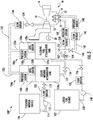
- FIG.1 also illustrates one embodiment of a system 100 for transitioning the gas turbine 10 from burning gaseous fuel to liquid fuel and purging the residual liquid fuel from the system 100 after transfer back to the gaseous fuel.
- the system 100 includes a liquid fuel source 102 and a flushing medium source 104 for respectively providing liquid fuel and a flushing medium (e.g., demineralized water) to an accumulator tank 106.
- the liquid fuel source 102 and the flushing medium source 104 are preferably tanks, but may be a pipe line or any other suitable source.
- a liquid fuel pump 108 pumps liquid fuel from the liquid fuel source 102 through a liquid fuel conduit 110 to the accumulator tank 106.
- a flushing medium pump 112 pumps flushing medium from the flushing medium source 104 through a flushing medium conduit 114 to the accumulator tank 106.
- a liquid fuel conduit valve 116 controls the flow of liquid fuel through the liquid fuel conduit 110
- a flushing medium conduit valve 118 controls the flow of flushing medium through the flushing medium conduit 114.
- the liquid fuel conduit 110 and the flushing medium conduit 114 may optionally include a liquid fuel conduit pressure sensor 120 and/or a flushing medium sensor 122, respectively.
- the accumulator tank 106 stores a volume of liquid 124 and a volume of motive gas 126 (e.g., pressurized air), which pressurizes the volume of liquid 124.
- the volume of motive gas 126 forces the volume of liquid 124 out of the accumulator tank 106.
- the volume of liquid 124 is alternately liquid fuel or flushing medium. That is, the volume of liquid 124 is either liquid fuel or flushing medium depending on the progress of the fuel transition, but not both at the same time.
- the flushing medium conduit valve 118 remains closed when the volume of liquid 124 is liquid fuel
- the liquid fuel conduit valve 116 remains closed when the volume of liquid 124 is flushing medium.
- the accumulator tank 106 may include an accumulator tank level sensor 128 for measuring the measuring the level or height of the volume of liquid 124 therein. As illustrated in FIG. 2 , the accumulator tank level sensor 128 communicates with a fuel transfer controller 130. In this respect, the fuel transfer controller 130 may modulate the liquid fuel pump 108, flushing medium pump 112, liquid fuel conduit valve 116, and flushing medium conduit valve 118 to maintain the proper level of the volume of liquid 124 in the accumulator tank 106 based on feedback from the accumulator tank level sensor 128 and, if included, the liquid fuel conduit and flushing medium conduit flow sensors 120, 122.
- the system 100 includes a motive gas conduit 132 for supplying motive gas to the accumulator tank 106.
- the motive gas conduit 132 includes a motive gas conduit valve 134 for controlling the flow of motive gas to the accumulator tank 106.
- the motive gas conduit 132 may include a motive gas conduit flow sensor 136.
- the motive gas flowing through the motive gas conduit 132 may be pressurized bled air from the compressor 12.
- an alternate embodiment of the system 100' may include a stand-alone motive gas pump 138 to provide pressurized air to the motive gas conduit 132.
- the stand-alone motive gas pump 136 is a separate and distinct component from the gas turbine 10.
- the accumulator tank 106 may include an accumulator tank pressure sensor 140 ( FIG. 1 ) for measuring the pressure of the volume of motive gas 126 therein. As illustrated in FIG. 2 , the accumulator tank pressure sensor 140 communicates with the fuel transfer controller 130. In this respect, the fuel transfer controller 130 may modulate the motive gas conduit valve 134 and/or the motive gas pump 138 to maintain the proper pressure of the volume of motive gas 126 in the accumulator tank 106 based on feedback from the accumulator tank pressure sensor 140 and, if included, the motive gas conduit flow sensor 136.
- the system 100 further includes a turbine conduit 142 for supplying the volume of liquid 124 (i.e., liquid fuel or flushing medium) to the gas turbine 10, and more specifically to the liquid fuel manifold 22, for combustion thereof.
- the turbine conduit 142 includes a turbine conduit valve 144, which controls the flow of the volume of liquid 124 into the turbine conduit 142. That is, the turbine conduit valve 144 permits the volume of liquid 124 to flow to the liquid fuel manifold 22 when open and prevents the volume of liquid 124 from flowing to the liquid fuel manifold 22 when closed.
- the turbine conduit 142 may optionally include a turbine conduit flow sensor 146 and/or a turbine conduit pressure sensor 148.
- the fuel transfer controller 130 communicates with a turbine controller 150, which controls the gas turbine 10.
- the turbine controller 150 monitors, inter alia, the pressure of the gaseous fuel supplied to the gas turbine 10. As long as the gaseous fuel pressure is sufficient and the transfer is not manually initiated, the fuel transfer controller 130 keeps the turbine conduit valve 144 closed. If the fuel transfer is manually initiated or the turbine controller 150 determines that the gaseous fuel pressure is too low or decaying at a predetermined rate due to the loss of gas compression, the fuel transfer controller 130 opens the turbine conduit valve 144, thereby permitting the volume of liquid 124 (in this case liquid fuel) to flow to the liquid fuel manifold 22. That is, the fuel source transfer may occur manually based on user input or automatically based on fuel pressure. In the embodiment illustrated in FIGS. 2 and 4 , the fuel transfer controller 130 and the turbine controller 150 are separate controllers. Although, the fuel transfer controller 130 may be integrated into the turbine controller 150.
- a system 100" includes separate accumulator tanks for the liquid fuel and the flushing medium.
- the liquid fuel source 102 supplies liquid fuel to a liquid fuel accumulator tank 106a
- the flushing medium source 104 supplies flushing medium to a flushing medium accumulator tank 106b.
- the liquid fuel conduit 110 and the flushing medium conduit 114 respectively supply liquid fuel and flushing medium to the liquid fuel and flushing medium accumulator tanks 106a, 106b in the same manner as in systems 100, 100'.
- the liquid fuel accumulator tank 106a stores a volume of liquid fuel 124a and a first volume of motive gas 126a, which pressurizes the volume of liquid fuel 124a.
- the flushing medium accumulator tank 106b stores a volume of flushing medium 124b and a second volume of motive gas 126b, which pressurizes the volume of flushing medium 124b.
- the first and second volumes of motive gas 126a, 126b respectively force the volume of liquid fuel 124a and the volume of flushing medium 124b out of the liquid fuel and flushing medium accumulator tanks 106a, 106b.
- the liquid fuel and flushing medium accumulator tanks 106a, 106b may respectively include a liquid fuel accumulator tank level sensor 128a and a flushing medium accumulator tank level sensor 128b for respectively measuring the level or height of the volume of liquid fuel 124a and the volume of flushing medium 124b therein.
- the fuel transfer controller 130 may independently modulate the liquid fuel pump 108, flushing medium pump 112, liquid fuel conduit valve 116, and flushing medium conduit valve 118 to maintain the proper level of the volume of liquid fuel 124a and the volume of flushing medium 124b in the same manner as in system 100, 100'.
- the system 100" may supply motive gas to the liquid fuel and flushing medium accumulator tanks 106a, 106b through the motive gas conduit 132 in the same manner as in the systems 100, 100'.
- the motive gas conduit 132 splits into a liquid fuel accumulator tank branch 132a and a flushing medium accumulator tank branch 132b.
- the motive gas conduit valve 134 is upstream of the branches 132a, 132b.
- motive gas flows into the liquid fuel and flushing medium accumulator tanks 106a, 106b at the same time, in the same flow rate, and at the same pressure.
- the branches 132a, 132b may optionally include valves (not shown) for independently adjusting the timing, flow rate, or pressure of the motive gas delivered to the liquid fuel and flushing medium accumulator tanks 106a, 106b.
- the liquid fuel and flushing medium accumulator tanks 106a, 106b may respectively include a liquid fuel accumulator tank pressure sensor 140a and a flushing medium accumulator tank pressure sensor 140b for respectively measuring the pressure of the first and the second volumes of motive gas 126a, 126b therein.
- the fuel transfer controller 130 may independently modulate the motive gas conduit valve 134, the motive gas pump 138, and/or any other valves to maintain the proper pressure of the volume of motive gas 126 in the accumulator tank 106 in the same manner as in the systems 100, 100'.
- the turbine conduit 142 supplies the volume of liquid fuel 124a from the liquid fuel accumulator tank 106a to the liquid fuel manifold 22 for combustion thereof in the same manner as the systems 100, 100'.
- the turbine conduit 142 includes a check valve 152 disposed upstream of the turbine conduit valve 144. The check valve 152 prevents liquid in the turbine conduit 142 from flowing in the reverse direction back into the liquid fuel accumulator tank 106a.
- the system 100" further includes a flushing medium injection conduit 154 for supplying the volume of flushing medium 124b to the gas turbine 10, and more specifically to the water injection manifold 24.
- the flushing medium injection conduit 154 includes a flushing medium injection conduit valve 156, which controls the flow of the volume of flushing medium 124b exiting the flushing medium accumulator tank 106b.
- the flushing medium injection conduit 154 may optionally include a flushing medium injection conduit flow sensor 158 and/or a flushing medium injection conduit pressure sensor 160.
- a transfer conduit 162 fluidly couples the turbine conduit 142 and the flushing medium injection conduit 154.
- the transfer conduit 162 permits at least a portion of the volume of flushing medium 124b to flow into the turbine conduit 142 to the liquid fuel manifold 22.
- the transfer conduit 162 connects to the turbine conduit 142 downstream of the check valve 152 and upstream of the turbine conduit valve 144.
- the check valve 152 prevents the flushing medium from flowing into the liquid fuel accumulator tank 106a, and the turbine conduit valve 144 controls the flow of flushing medium to the liquid fuel manifold 22.
- the transfer conduit 162 connects to a three-way valve 164 disposed in the flushing medium injection conduit 154 downstream of the flushing medium injection conduit valve 156.
- the three-way valve 164 controls the destination of the volume of flushing medium 124b leaving the flushing medium accumulator tank 106b. More specifically, the three-way valve 164 directs the volume of flushing medium 124b to the water injection manifold 24 by blocking access to the transfer conduit 162. Analogously, the three-way valve 164 directs the volume of flushing medium 124b to the liquid fuel manifold 22 by opening access to the transfer conduit 162 and blocking access to the portion of the flushing medium injection conduit 154 downstream of the three-way valve 164. As illustrated in FIG. 6 , the fuel transfer controller 130 may control the operation of the three-way valve 164.
- the liquid fuel conduit valve 116, the flushing medium conduit valve 118, the motive gas conduit valve 134, the turbine conduit valve 144, and flushing medium injection conduit valve 154 may be globe valves, gate valves, butterfly valves, ball valves, or any other type of valve.
- the three-way valve 164 may be an electrically controlled solenoid valve or any other type of three-way valve.
- the valves 116, 118, 134, 144, 154, 164 in the systems 100, 100', 100" may be electrically controlled via the fuel transfer controller 130 or the turbine controller 150. Alternately, the valves 116, 118, 134, 144, 154, 164 may be manually controlled.
- the fuel transfer controller 130 may comprise any combination of microprocessors, circuitry, or other programmed logic circuit and is not limited to any particular hardware architecture or configuration. Embodiments of the systems and methods set forth herein may be implemented by one or more general-purpose or customized controllers 130 adapted in any suitable manner to provide the desired functionality.
- the controller 130 may be adapted to provide additional functionality, either complementary or unrelated to the present subject matter.
- one or more controllers 130 may be adapted to provide the described functionality by accessing software instructions rendered in a computer-readable form.
- any suitable programming, scripting, or other type of language or combinations of languages may be used to implement the teachings contained herein. Nevertheless, software need not be used exclusively, or at all.
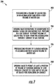
- FIG. 7 is a flowchart illustrating an exemplary method (200) for transitioning the gas turbine 10 from burning gaseous fuel to liquid fuel and purging the liquid fuel from the systems 100, 100', 100" after transfer back to the gaseous fuel.
- the volume of motive gas 126, 126a pressurizes the volume of liquid fuel 124a in the accumulator tank 106 ( FIGS. 1 and 3 ) or liquid fuel accumulator tank 106a ( FIG. 5 ).
- the liquid fuel pump 108 may pump a volume of liquid fuel 124a from the liquid fuel source 102 into the accumulator tank 106 ( FIGS. 1 and 3 ) or liquid fuel accumulator tank 106a ( FIG. 5 ).
- the accumulator tank level sensor 128 (FIGS. land 3) or the liquid fuel accumulator tank level sensor 128a ( FIG. 5 ) may provide feedback to the fuel transfer controller 130, which modulates the liquid fuel pump 108 as needed to reach the desired level of the volume of liquid fuel 124a.
- the controller 130 may also modulate the motive gas conduit valve 134 and, if present, the motive gas pump 138 in response to feedback from the accumulator tank pressure sensor 140 ( FIGS. 1 and 3 ) or liquid fuel accumulator tank pressure sensor 140a ( FIG. 5 ) to maintain the desired pressure in the accumulator tank 106 ( FIGS. 1 and 3 ) or the liquid fuel accumulator tank 106a ( FIG. 5 ).
- the fuel transfer controller 130 opens the turbine conduit valve 144 in response to a manual signal to transfer fuel sources or low gaseous fuel pressure in the fuel supply system of the gas turbine 10.
- the fuel transfer controller 130 is communication with the turbine controller 150, which preferably monitors gaseous fuel pressure.
- the pressure in the accumulator tank 106 ( FIGS. 1 and 3 ) or the liquid fuel accumulator tank 106a ( FIG. 5 ) created by the volume of motive gas 126, 126a forces the volume of liquid fuel 124a through the turbine conduit 142 for eventual delivery to the liquid manifold 22.
- the fuel transfer controller 130 closes the turbine conduit valve 144.
- the fuel transfer controller 130 may optionally open the flushing medium injection conduit valve 156 if the flushing medium accumulator tank 106b has been filled with the volume of flushing medium 124b in accordance with step (206), discussed below.
- the flushing medium injection conduit valve 156 permits a portion of the volume of the flushing medium 124b to flow to the water injection manifold 24. This may be advantageous when the flushing medium, e.g., demineralized water, is used for flame stabilization in the combustor 14.
- the three-way valve 164 should be positioned to block flow to the transfer conduit 162. After delivery of the volume of liquid fuel 124a to the liquid fuel manifold 22, the fuel transfer controller 130 switches the position of the three-way valve 164 to open the transfer conduit 162 and block the downstream portion of the flushing medium injection conduit 154.
- step (206) the volume of motive gas 126, 126b pressurizes the volume of flushing medium 124b in the accumulator tank 106 ( FIGS. 1 and 3 ) or flushing medium accumulator tank 106b ( FIG. 5 ).
- the flushing medium pump 112 may pump the volume of flushing medium 124b from the flushing medium source 104 into the accumulator tank 106 ( FIGS. 1 and 3 ) or flushing medium accumulator tank 106b ( FIG. 5 ).
- the accumulator tank level sensor 128 FIGS. land 3) or the flushing medium accumulator tank level sensor 128b ( FIG.
- step (206) may be done before, during, or after step (202).
- step (208) at least a portion of the volume of flushing medium 124b flows through the turbine conduit 142 after the entire volume of liquid fuel was burned, thereby flushing any residual liquid fuel therefrom.
- the step (208) may occur after the gas turbine 10 has switched back to operating the primary fuel.
- the fuel transfer controller 130 opens the turbine conduit valve 144.
- the pressure in the accumulator tank 106 created by the volume of motive gas 126 forces the volume of flushing medium 124b through the turbine conduit 142 for eventual delivery to the liquid manifold 22.
- any residual liquid fuel is flushed from the turbine conduit 142.
- the fuel transfer controller 130 closes the turbine conduit valve 144.
- the fuel transfer controller 130 opens the flushing medium injection conduit valve 156.
- the pressure in the flushing medium accumulator tank 106b created by the volume of motive gas 126b forces the volume of flushing medium 124b into the flushing medium injection conduit 142.
- the three-way valve 164 directs the volume of flushing medium 124b in the transfer conduit 162, which directs the volume of flushing medium 124b to the turbine conduit 142. In this respect, any residual liquid fuel is flushed from the turbine conduit 142.
- the fuel transfer controller 130 closes the flushing medium injection conduit valve 156.
- the liquid fuel pump 108 may pump another volume of liquid fuel 124a from the liquid fuel source 102 into the accumulator tank 106 ( FIGS. 1 and 3 ) or liquid fuel accumulator tank 106a ( FIG. 5 ). Motive gas may then pressurize the volume of liquid fuel 124a.
- the flushing medium pump 112 may pump another volume of flushing medium 124b from the flushing medium source 104 into the flushing medium accumulator tank 106b. Motive gas may then pressurize the volume of flushing medium 124b.
- the systems 100, 100', 100" and the method (200) permits the gas turbine 10 to switch from a gaseous fuel (e.g., natural gas) to a liquid fuel (e.g., diesel) without requiring shut down thereof.
- a gaseous fuel e.g., natural gas
- a liquid fuel e.g., diesel
- power plant availability and capacity are improved.
- the systems 100, 100', 100" and the method (200) purge any residual liquid fuel therefrom to prevent coke deposits from forming, thereby improving reliability and reducing failed fuel transfers. In fact, all valves and other components that supply liquid fuel to the gas turbine 10 are flushed.
- the systems 100, 100', 100" and the method (200) are easily implementable on existing gas turbines.
Landscapes
- Engineering & Computer Science (AREA)
- Chemical & Material Sciences (AREA)
- Combustion & Propulsion (AREA)
- Mechanical Engineering (AREA)
- General Engineering & Computer Science (AREA)
- Engine Equipment That Uses Special Cycles (AREA)
Abstract
Description
- The present subject matter relates to a gas turbine. More particularly, the present subject matter relates to a method and system for transitioning a gas turbine from burning gaseous fuel to liquid fuel and purging the liquid fuel from the system after transfer back to the gaseous fuel.
- Gas turbines are used globally for power generation and various process applications. A gas turbine generally includes a compressor section, a combustion section, a turbine section, and an exhaust section. The compressor section progressively increases the pressure of a working fluid entering the gas turbine and supplies this compressed working fluid to the combustion section. The compressed working fluid and a fuel (e.g., natural gas) mix within the combustion section and burn in a combustion chamber to generate high pressure and high temperature combustion gases. The combustion gases flow from the combustion section into the turbine section where they expand to produce work. For example, expansion of the combustion gases in the turbine section may rotate a shaft connected to a generator, thereby producing electricity. The combustion gases then exit the gas turbine via the exhaust section.
- One of the primary advantages of a gas turbine is the ability to run on a variety of fuels. For example, gas turbines may burn heavy fuel oils, naphtha, distillate, flare gas, syngas, landfill gas, and natural gas. This is particularly advantageous in parts of the world that suffer from normal and seasonal shortages of various fuels or have an abundance of multiple different fuel types. As a result, many power plant owners operate gas turbines capable of burning multiple fuel combinations. For example, some gas turbines burn natural gas as a primary fuel and diesel or distillate as a backup fuel. Preferably, the gas turbine is able to automatically transfer between fuel types.
- In order to facilitate automatic fuel transfer, some gas turbines include methods and systems implementable on short notice to facilitate a fuel change (e.g., from natural gas to diesel) while maintaining a high percentage of base power output. The standard approach rapidly reduces the load on the gas turbine to some predetermined value based on a valid determination that there will be a loss of or substantial reduction in natural gas pressure, while simultaneously transferring to and ramping up the backup fuel supply. This process requires purging and prefilling of the backup system and reducing the primary fuel flow by closing the main supply valve or gas control valve (GCV).
- The success of the traditional response is dependent on the rate of decay of the primary fuel pressure and the time to vent and prime the backup fuel supply system. Rapid activation and transition to the full operation of the backup fuel supply system strains the gas turbine components and control system. The need to maintain power output while the gas turbine experiences fuel system, combustion system, and power generation transients further complicates the process.
- Although known transfer processes are generally successful, system reliability issues may arise. In systems using diesel as the backup fuel, residual liquid fuel in the supply lines hardens into coke deposits after switching back to gaseous fuel and operating continuously thereon for about five days. These coke deposits may reduce overall supply line diameter. Additionally, coke formation hinders the proper functioning of spring-operated check valves and three-way valves and may even clog critical fuel system components (e.g., distributor valves, fuel flow check valves, fuel lines, etc.). Furthermore, coke formation in the liquid fuel lines leading to the combustion cans may reduce the probability of a successful transfer back to liquid fuel.
- The prior art generally includes two type systems that seek to mitigate the coking problem, but each system has drawbacks. Liquid fuel recirculating systems continually recirculate liquid fuel back to a supply tank, thereby preventing fuel stagnation in a portion of the supply lines. But, the recirculation occurs upstream of the distribution valves, check valves, and other components. As such, these components may still suffer from coking. Nitrogen purge systems use nitrogen gas to blow out residual liquid fuel in the supply lines. Although these types of systems are generally effective, they require that the gas turbine stop for the liquid fuel system purge before operating on gaseous fuel, thereby impacting plant availability. Furthermore, both types of prior art systems are capital intensive and may negatively impact production efficiency throughout the operating year. Moreover, both systems may be ineffective in areas of the world where gaseous fuel supplies are sporadic or where no additional downtime to clean system components after a failed transfer or restart is available.
- Accordingly, a method and system for permitting a gas turbine to quickly transition from operating on gaseous fuel to liquid fuel and for purging the liquid fuel supply lines after transitioning back to gaseous fuel would be useful in the art.
- Aspects and advantages of the invention are set forth below in the following description, or may be obvious from the description, or may be learned through practice of the invention.
- In one aspect, the present subject matter is directed to a system for transferring the type of fuel supplied to a gas turbine. The system includes an accumulator for alternatively storing a first combination comprising a volume of liquid fuel and a first volume of motive gas and a second combination comprising a volume of flushing medium and a second volume of motive gas. The first volume of motive gas exerts pressure on the volume of liquid fuel, and the second volume of motive gas exerts pressure on the volume of flushing medium. A conduit couples the accumulator to a gas turbine. A motive gas source provides the first volume of motive gas and the second volume of motive gas to the accumulator. A valve opens in response to low gaseous fuel pressure in the gas turbine to permit the volume of liquid fuel to flow through the conduit to the gas turbine. The valve also opens to permit at least a portion of the volume of flushing medium to flow through the conduit to flush any of the volume of liquid fuel remaining in the conduit after the entire volume of liquid fuel has been consumed by the gas turbine.
- Another aspect of the present subject matter is directed to an alternate embodiment of a system for transferring the type of fuel supplied to a gas turbine. The alternate embodiment includes a first accumulator for storing a volume of liquid fuel and a first volume of motive gas. The first volume of motive gas exerts pressure on the volume of liquid fuel. A first conduit couples the first accumulator to a gas turbine. A second accumulator stores a volume of flushing medium and a second volume of motive gas. The second volume of motive gas exerts pressure on the volume of flushing medium. A second conduit couples the second accumulator to the first conduit. A motive gas source provides the first volume of motive gas and the second volume of motive gas to the first and the second accumulators, respectively. A first valve opens in response to low gaseous fuel pressure in the gas turbine to permit the volume of liquid fuel to flow from the first accumulator through the first conduit to the gas turbine. A second valve in the second conduit permits at least a portion of the volume of flushing medium to flow through the first conduit to flush any of the volume of liquid fuel remaining in the first conduit after the entire volume of liquid fuel has been consumed by the gas turbine.
- In a further aspect, the present subject matter includes a method of transferring the type of fuel supplied to a gas turbine. The method includes pressurizing a volume of liquid fuel in an accumulator with a first volume of motive gas. A valve opens in response to low gaseous fuel pressure in the gas turbine to permit the volume of liquid fuel to flow from the accumulator through a conduit to the gas turbine. A volume of flushing medium is pressurized in the accumulator with a second volume of motive gas. The valve opens to permit at least a portion of the volume of flushing medium to flow through the conduit to flush any of the volume of liquid fuel remaining in the conduit after the gas turbine engine consumes the volume of liquid fuel.
- Those of ordinary skill in the art will better appreciate the features and aspects of such embodiments, and others, upon review of the specification.
- A full and enabling disclosure of the present invention, including the best mode thereof to one skilled in the art, is set forth more particularly in the remainder of the specification, including reference to the accompanying figures, in which:
-
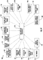
FIG. 1 is a schematic view of one embodiment of a system for transitioning a gas turbine from burning gaseous fuel to liquid fuel and purging the liquid fuel from the system after transfer back to the gaseous fuel in accordance with the embodiments disclosed herein; -
FIG. 2 is another schematic view of the system shown inFIG. 1 , further illustrating a controller in communication with the various components of the system; -
FIG. 3 is a schematic view of an alternate embodiment of the system shown inFIG. 1 , illustrating a stand-alone pump for supplying motive gas; -
FIG. 4 is another schematic view of the embodiment of the system shown inFIG. 3 , further illustrating the controller in communication with the various components of the system; -
FIG. 5 is a schematic view of a further alternate embodiment of the system shown inFIG. 1 , illustrating a flushing medium accumulator tank and a liquid fuel accumulator tank; -
FIG. 6 is another schematic view of the embodiment of the system shown inFIG. 5 , further illustrating the controller in communication with the various components of the system; and -
FIG. 7 is a flowchart illustrating an example of a method for transitioning a gas turbine from burning gaseous fuel to liquid fuel and purging the liquid fuel from the system after transfer back to the gaseous fuel in accordance with the embodiments disclosed herein. - Reference will now be made in detail to present embodiments of the invention, one or more examples of which are illustrated in the accompanying drawings. The detailed description uses numerical and letter designations to refer to features in the drawings. Like or similar designations in the drawings and description have been used to refer to like or similar parts of the invention. As used herein, the terms "first", "second", and "third" may be used interchangeably to distinguish one component from another and are not intended to signify location or importance of the individual components. The terms "upstream" and "downstream" refer to the relative direction with respect to fluid flow in a fluid pathway. For example, "upstream" refers to the direction from which the fluid flows, and "downstream" refers to the direction to which the fluid flows.
- Each example is provided by way of explanation of the invention, not limitation of the invention. In fact, it will be apparent to those skilled in the art that modifications and variations can be made in the present invention without departing from the scope or spirit thereof. For instance, features illustrated or described as part of one embodiment may be used on another embodiment to yield a still further embodiment. Thus, it is intended that the present invention covers such modifications and variations as come within the scope of the appended claims and their equivalents.
- The present subject matter disclosed herein relates to systems and methods for transitioning a gas turbine from burning gaseous fuel to liquid fuel and purging the liquid fuel from the system after transfer back to the gaseous fuel. More specifically, the systems and methods provide liquid fuel to the gas turbine temporarily while the gas turbine transitions from a gaseous fuel source to a long-term liquid fuel source. That is, the systems and method provide a volume of liquid fuel to sustain the gas turbine while one or more pumps in the long-term liquid fuel start up to provide a long-term supply of liquid fuel. Furthermore, the systems and methods provided herein purge any residual fuel in the liquid fuel lines after use to prevent coke deposits from forming therein.
- Now referring to the drawings, wherein identical numerals indicate the same elements throughout the figures,
FIG. 1 schematically illustrates agas turbine system 10. It should be understood that theturbine system 10 of the present disclosure need not be agas turbine system 10, but rather may be any suitable turbine system, such as a steam turbine system or other suitable system. Thegas turbine system 10 may include acompressor 12, acombustor 14, and aturbine 16. Thecompressor 12 andturbine 16 may be coupled by ashaft 18. Theshaft 18 may be a single shaft or a plurality of shaft segments coupled together to formshaft 18. - As is generally known in the art, the
compressor 12 compresses air or another suitable working fluid flowing therethrough. The compressed working fluid flows to thecombustor 14, where it is mixed with fuel and combusted to create high temperature and high pressure combustion gases. The combustion gases exit thecombustor 14 and flow into theturbine 16, which extracts kinetic energy from the combustion gases to drive theshaft 18. For example, rotation of theshaft 18 may drive thecompressor 12, which compresses the working fluid. Alternately or in addition, theshaft 18 may connect theturbine 16 to agenerator 20 for producing electricity. - The
gas turbine 10 may be capable of operating on two or different types of fuels. For example, thegas turbine 10 may be able to burn two or more of the following fuels: heavy fuel oils, naphtha, distillate, flare gas, syngas, landfill gas, and natural gas. In one embodiment, thegas turbine 10 primarily operates on a gaseous fuel (e.g., natural gas), but also be able to burn a liquid fuel (e.g., diesel) when the gaseous fuel is unavailable. In this respect, thegas turbine 10 may include a gaseous fuel manifold (not shown) and aliquid fuel manifold 22 for respectively supplying gaseous fuel and liquid fuel to thecombustor 14. Although the embodiment shown inFIG.1 uses a gaseous fuel as the primary fuel and a liquid fuel as the secondary fuel, the primary fuel and the secondary fuel may be either gaseous or liquid. In some embodiments, thegas turbine 10 may include awater injection manifold 24 for injecting water into thecombustor 14 to maintain flame stability therein. -
FIG.1 also illustrates one embodiment of asystem 100 for transitioning thegas turbine 10 from burning gaseous fuel to liquid fuel and purging the residual liquid fuel from thesystem 100 after transfer back to the gaseous fuel. Thesystem 100 includes aliquid fuel source 102 and a flushingmedium source 104 for respectively providing liquid fuel and a flushing medium (e.g., demineralized water) to anaccumulator tank 106. Theliquid fuel source 102 and the flushingmedium source 104 are preferably tanks, but may be a pipe line or any other suitable source. Aliquid fuel pump 108 pumps liquid fuel from theliquid fuel source 102 through aliquid fuel conduit 110 to theaccumulator tank 106. Similarly, a flushingmedium pump 112 pumps flushing medium from the flushingmedium source 104 through a flushingmedium conduit 114 to theaccumulator tank 106. A liquidfuel conduit valve 116 controls the flow of liquid fuel through theliquid fuel conduit 110, and a flushingmedium conduit valve 118 controls the flow of flushing medium through the flushingmedium conduit 114. Theliquid fuel conduit 110 and the flushingmedium conduit 114 may optionally include a liquid fuelconduit pressure sensor 120 and/or a flushingmedium sensor 122, respectively. - The
accumulator tank 106 stores a volume ofliquid 124 and a volume of motive gas 126 (e.g., pressurized air), which pressurizes the volume ofliquid 124. As will be discussed in greater detail later, the volume ofmotive gas 126 forces the volume ofliquid 124 out of theaccumulator tank 106. In the embodiment illustrated inFIG. 1 , the volume ofliquid 124 is alternately liquid fuel or flushing medium. That is, the volume ofliquid 124 is either liquid fuel or flushing medium depending on the progress of the fuel transition, but not both at the same time. In this respect, the flushingmedium conduit valve 118 remains closed when the volume ofliquid 124 is liquid fuel, and the liquidfuel conduit valve 116 remains closed when the volume ofliquid 124 is flushing medium. - The
accumulator tank 106 may include an accumulatortank level sensor 128 for measuring the measuring the level or height of the volume ofliquid 124 therein. As illustrated inFIG. 2 , the accumulatortank level sensor 128 communicates with afuel transfer controller 130. In this respect, thefuel transfer controller 130 may modulate theliquid fuel pump 108, flushingmedium pump 112, liquidfuel conduit valve 116, and flushingmedium conduit valve 118 to maintain the proper level of the volume ofliquid 124 in theaccumulator tank 106 based on feedback from the accumulatortank level sensor 128 and, if included, the liquid fuel conduit and flushing mediumconduit flow sensors - The
system 100 includes amotive gas conduit 132 for supplying motive gas to theaccumulator tank 106. Themotive gas conduit 132 includes a motivegas conduit valve 134 for controlling the flow of motive gas to theaccumulator tank 106. Optionally, themotive gas conduit 132 may include a motive gasconduit flow sensor 136. In the embodiment illustrated inFIG. 1 , the motive gas flowing through themotive gas conduit 132 may be pressurized bled air from thecompressor 12. As illustrated inFIG. 3 , an alternate embodiment of the system 100' may include a stand-alonemotive gas pump 138 to provide pressurized air to themotive gas conduit 132. The stand-alonemotive gas pump 136 is a separate and distinct component from thegas turbine 10. - The
accumulator tank 106 may include an accumulator tank pressure sensor 140 (FIG. 1 ) for measuring the pressure of the volume ofmotive gas 126 therein. As illustrated inFIG. 2 , the accumulatortank pressure sensor 140 communicates with thefuel transfer controller 130. In this respect, thefuel transfer controller 130 may modulate the motivegas conduit valve 134 and/or themotive gas pump 138 to maintain the proper pressure of the volume ofmotive gas 126 in theaccumulator tank 106 based on feedback from the accumulatortank pressure sensor 140 and, if included, the motive gasconduit flow sensor 136. - The
system 100 further includes aturbine conduit 142 for supplying the volume of liquid 124 (i.e., liquid fuel or flushing medium) to thegas turbine 10, and more specifically to theliquid fuel manifold 22, for combustion thereof. Theturbine conduit 142 includes aturbine conduit valve 144, which controls the flow of the volume ofliquid 124 into theturbine conduit 142. That is, theturbine conduit valve 144 permits the volume ofliquid 124 to flow to theliquid fuel manifold 22 when open and prevents the volume of liquid 124 from flowing to theliquid fuel manifold 22 when closed. Theturbine conduit 142 may optionally include a turbineconduit flow sensor 146 and/or a turbineconduit pressure sensor 148. - As illustrated in
FIG. 2 , thefuel transfer controller 130 communicates with aturbine controller 150, which controls thegas turbine 10. Theturbine controller 150 monitors, inter alia, the pressure of the gaseous fuel supplied to thegas turbine 10. As long as the gaseous fuel pressure is sufficient and the transfer is not manually initiated, thefuel transfer controller 130 keeps theturbine conduit valve 144 closed. If the fuel transfer is manually initiated or theturbine controller 150 determines that the gaseous fuel pressure is too low or decaying at a predetermined rate due to the loss of gas compression, thefuel transfer controller 130 opens theturbine conduit valve 144, thereby permitting the volume of liquid 124 (in this case liquid fuel) to flow to theliquid fuel manifold 22. That is, the fuel source transfer may occur manually based on user input or automatically based on fuel pressure. In the embodiment illustrated inFIGS. 2 and4 , thefuel transfer controller 130 and theturbine controller 150 are separate controllers. Although, thefuel transfer controller 130 may be integrated into theturbine controller 150. - In further alternate embodiment, a
system 100" includes separate accumulator tanks for the liquid fuel and the flushing medium. In this respect, theliquid fuel source 102 supplies liquid fuel to a liquidfuel accumulator tank 106a, and the flushingmedium source 104 supplies flushing medium to a flushingmedium accumulator tank 106b. Theliquid fuel conduit 110 and the flushingmedium conduit 114 respectively supply liquid fuel and flushing medium to the liquid fuel and flushingmedium accumulator tanks systems 100, 100'. The liquidfuel accumulator tank 106a stores a volume ofliquid fuel 124a and a first volume ofmotive gas 126a, which pressurizes the volume ofliquid fuel 124a. The flushingmedium accumulator tank 106b stores a volume of flushing medium 124b and a second volume ofmotive gas 126b, which pressurizes the volume of flushing medium 124b. As will be discussed in greater detail later, the first and second volumes ofmotive gas liquid fuel 124a and the volume of flushing medium 124b out of the liquid fuel and flushingmedium accumulator tanks - The liquid fuel and flushing
medium accumulator tanks tank level sensor 128a and a flushing medium accumulatortank level sensor 128b for respectively measuring the level or height of the volume ofliquid fuel 124a and the volume of flushing medium 124b therein. As illustrated inFIG. 6 , thefuel transfer controller 130 may independently modulate theliquid fuel pump 108, flushingmedium pump 112, liquidfuel conduit valve 116, and flushingmedium conduit valve 118 to maintain the proper level of the volume ofliquid fuel 124a and the volume of flushing medium 124b in the same manner as insystem 100, 100'. - The
system 100" may supply motive gas to the liquid fuel and flushingmedium accumulator tanks motive gas conduit 132 in the same manner as in thesystems 100, 100'. Themotive gas conduit 132 splits into a liquid fuelaccumulator tank branch 132a and a flushing mediumaccumulator tank branch 132b. In one embodiment, the motivegas conduit valve 134 is upstream of thebranches medium accumulator tanks branches medium accumulator tanks - The liquid fuel and flushing
medium accumulator tanks tank pressure sensor 140a and a flushing medium accumulatortank pressure sensor 140b for respectively measuring the pressure of the first and the second volumes ofmotive gas FIG. 6 , thefuel transfer controller 130 may independently modulate the motivegas conduit valve 134, themotive gas pump 138, and/or any other valves to maintain the proper pressure of the volume ofmotive gas 126 in theaccumulator tank 106 in the same manner as in thesystems 100, 100'. - The
turbine conduit 142 supplies the volume ofliquid fuel 124a from the liquidfuel accumulator tank 106a to theliquid fuel manifold 22 for combustion thereof in the same manner as thesystems 100, 100'. In the embodiment illustrated inFIG. 5 , theturbine conduit 142 includes acheck valve 152 disposed upstream of theturbine conduit valve 144. Thecheck valve 152 prevents liquid in theturbine conduit 142 from flowing in the reverse direction back into the liquidfuel accumulator tank 106a. - The
system 100" further includes a flushingmedium injection conduit 154 for supplying the volume of flushing medium 124b to thegas turbine 10, and more specifically to thewater injection manifold 24. The flushingmedium injection conduit 154 includes a flushing mediuminjection conduit valve 156, which controls the flow of the volume of flushing medium 124b exiting the flushingmedium accumulator tank 106b. The flushingmedium injection conduit 154 may optionally include a flushing medium injectionconduit flow sensor 158 and/or a flushing medium injectionconduit pressure sensor 160. - A
transfer conduit 162 fluidly couples theturbine conduit 142 and the flushingmedium injection conduit 154. In this respect, thetransfer conduit 162 permits at least a portion of the volume of flushing medium 124b to flow into theturbine conduit 142 to theliquid fuel manifold 22. In particular, thetransfer conduit 162 connects to theturbine conduit 142 downstream of thecheck valve 152 and upstream of theturbine conduit valve 144. In this respect, thecheck valve 152 prevents the flushing medium from flowing into the liquidfuel accumulator tank 106a, and theturbine conduit valve 144 controls the flow of flushing medium to theliquid fuel manifold 22. Thetransfer conduit 162 connects to a three-way valve 164 disposed in the flushingmedium injection conduit 154 downstream of the flushing mediuminjection conduit valve 156. The three-way valve 164 controls the destination of the volume of flushing medium 124b leaving the flushingmedium accumulator tank 106b. More specifically, the three-way valve 164 directs the volume of flushing medium 124b to thewater injection manifold 24 by blocking access to thetransfer conduit 162. Analogously, the three-way valve 164 directs the volume of flushing medium 124b to theliquid fuel manifold 22 by opening access to thetransfer conduit 162 and blocking access to the portion of the flushingmedium injection conduit 154 downstream of the three-way valve 164. As illustrated inFIG. 6 , thefuel transfer controller 130 may control the operation of the three-way valve 164. - The liquid
fuel conduit valve 116, the flushingmedium conduit valve 118, the motivegas conduit valve 134, theturbine conduit valve 144, and flushing mediuminjection conduit valve 154 may be globe valves, gate valves, butterfly valves, ball valves, or any other type of valve. The three-way valve 164 may be an electrically controlled solenoid valve or any other type of three-way valve. Thevalves systems fuel transfer controller 130 or theturbine controller 150. Alternately, thevalves - As used herein, the
fuel transfer controller 130 may comprise any combination of microprocessors, circuitry, or other programmed logic circuit and is not limited to any particular hardware architecture or configuration. Embodiments of the systems and methods set forth herein may be implemented by one or more general-purpose or customizedcontrollers 130 adapted in any suitable manner to provide the desired functionality. Thecontroller 130 may be adapted to provide additional functionality, either complementary or unrelated to the present subject matter. For instance, one ormore controllers 130 may be adapted to provide the described functionality by accessing software instructions rendered in a computer-readable form. When software is used, any suitable programming, scripting, or other type of language or combinations of languages may be used to implement the teachings contained herein. Nevertheless, software need not be used exclusively, or at all. For example, as will be understood by those of ordinary skill in the art without required additional detailed discussion, some embodiments of the systems and methods set forth and disclosed herein may also be implemented by hard-wired logic or other circuitry, including, but not limited to application-specific circuits. Of course, various combinations of computer-executed software and hard-wired logic or other circuitry may be suitable, as well. -
FIG. 7 is a flowchart illustrating an exemplary method (200) for transitioning thegas turbine 10 from burning gaseous fuel to liquid fuel and purging the liquid fuel from thesystems motive gas liquid fuel 124a in the accumulator tank 106 (FIGS. 1 and3 ) or liquidfuel accumulator tank 106a (FIG. 5 ). In accordance with step (202), theliquid fuel pump 108 may pump a volume ofliquid fuel 124a from theliquid fuel source 102 into the accumulator tank 106 (FIGS. 1 and3 ) or liquidfuel accumulator tank 106a (FIG. 5 ). The accumulator tank level sensor 128 (FIGS. land 3) or the liquid fuel accumulatortank level sensor 128a (FIG. 5 ) may provide feedback to thefuel transfer controller 130, which modulates theliquid fuel pump 108 as needed to reach the desired level of the volume ofliquid fuel 124a. Thecontroller 130 may also modulate the motivegas conduit valve 134 and, if present, themotive gas pump 138 in response to feedback from the accumulator tank pressure sensor 140 (FIGS. 1 and3 ) or liquid fuel accumulatortank pressure sensor 140a (FIG. 5 ) to maintain the desired pressure in the accumulator tank 106 (FIGS. 1 and3 ) or the liquidfuel accumulator tank 106a (FIG. 5 ). - In step (204), the
fuel transfer controller 130 opens theturbine conduit valve 144 in response to a manual signal to transfer fuel sources or low gaseous fuel pressure in the fuel supply system of thegas turbine 10. Thefuel transfer controller 130 is communication with theturbine controller 150, which preferably monitors gaseous fuel pressure. In this respect, the pressure in the accumulator tank 106 (FIGS. 1 and3 ) or the liquidfuel accumulator tank 106a (FIG. 5 ) created by the volume ofmotive gas liquid fuel 124a through theturbine conduit 142 for eventual delivery to theliquid manifold 22. After delivery of the volume ofliquid fuel 124a to theliquid fuel manifold 22, thefuel transfer controller 130 closes theturbine conduit valve 144. - In the embodiment illustrated in
FIG. 5 , thefuel transfer controller 130 may optionally open the flushing mediuminjection conduit valve 156 if the flushingmedium accumulator tank 106b has been filled with the volume of flushing medium 124b in accordance with step (206), discussed below. In this respect, the flushing mediuminjection conduit valve 156 permits a portion of the volume of the flushing medium 124b to flow to thewater injection manifold 24. This may be advantageous when the flushing medium, e.g., demineralized water, is used for flame stabilization in thecombustor 14. The three-way valve 164 should be positioned to block flow to thetransfer conduit 162. After delivery of the volume ofliquid fuel 124a to theliquid fuel manifold 22, thefuel transfer controller 130 switches the position of the three-way valve 164 to open thetransfer conduit 162 and block the downstream portion of the flushingmedium injection conduit 154. - In step (206), the volume of
motive gas FIGS. 1 and3 ) or flushingmedium accumulator tank 106b (FIG. 5 ). In accordance with step (206), the flushingmedium pump 112 may pump the volume of flushing medium 124b from the flushingmedium source 104 into the accumulator tank 106 (FIGS. 1 and3 ) or flushingmedium accumulator tank 106b (FIG. 5 ). The accumulator tank level sensor 128 (FIGS. land 3) or the flushing medium accumulatortank level sensor 128b (FIG. 5 ) provide feedback to thefuel transfer controller 130, which may modulate the flushingmedium pump 112 as needed to reach the desired level of the volume of flushing medium 124b. Thecontroller 130 may also modulate the motivegas conduit valve 134 and, if present, themotive gas pump 138 in response to feedback from the accumulator tank pressure sensor 140 (FIGS. 1 and3 ) or flushing medium accumulatortank pressure sensor 140b (FIG. 5 ) to maintain the desired pressure in the accumulator tank 106 (FIGS. 1 and3 ) or the flushingmedium accumulator tank 106b (FIG. 5 ). With respect to thesystem 100" (FIG. 5 ), step (206) may be done before, during, or after step (202). - In step (208), at least a portion of the volume of flushing medium 124b flows through the
turbine conduit 142 after the entire volume of liquid fuel was burned, thereby flushing any residual liquid fuel therefrom. In particular, the step (208) may occur after thegas turbine 10 has switched back to operating the primary fuel. In thesystems 100, 100' (FIGS. 1 and3 ), thefuel transfer controller 130 opens theturbine conduit valve 144. In this respect, the pressure in theaccumulator tank 106 created by the volume ofmotive gas 126 forces the volume of flushing medium 124b through theturbine conduit 142 for eventual delivery to theliquid manifold 22. In this respect, any residual liquid fuel is flushed from theturbine conduit 142. After delivery of the volume of flushing medium 124b to theliquid fuel manifold 22, thefuel transfer controller 130 closes theturbine conduit valve 144. - In the
system 100", thefuel transfer controller 130 opens the flushing mediuminjection conduit valve 156. The pressure in the flushingmedium accumulator tank 106b created by the volume ofmotive gas 126b forces the volume of flushing medium 124b into the flushingmedium injection conduit 142. The three-way valve 164 directs the volume of flushing medium 124b in thetransfer conduit 162, which directs the volume of flushing medium 124b to theturbine conduit 142. In this respect, any residual liquid fuel is flushed from theturbine conduit 142. After delivery of the volume of flushing medium 124b to theliquid fuel manifold 22, thefuel transfer controller 130 closes the flushing mediuminjection conduit valve 156. - After flushing the residual liquid fuel from the
turbine conduit 142, theliquid fuel pump 108 may pump another volume ofliquid fuel 124a from theliquid fuel source 102 into the accumulator tank 106 (FIGS. 1 and3 ) or liquidfuel accumulator tank 106a (FIG. 5 ). Motive gas may then pressurize the volume ofliquid fuel 124a. Insystem 100" (FIG.5 ), the flushingmedium pump 112 may pump another volume of flushing medium 124b from the flushingmedium source 104 into the flushingmedium accumulator tank 106b. Motive gas may then pressurize the volume of flushing medium 124b. - In this respect, the
systems gas turbine 10 to switch from a gaseous fuel (e.g., natural gas) to a liquid fuel (e.g., diesel) without requiring shut down thereof. In this respect, power plant availability and capacity are improved. Furthermore, thesystems gas turbine 10 are flushed. Moreover, thesystems - It should be noted that, in some alternative implementations, the functions noted in the step may occur out of the order noted in the figures. For example, two steps shown in succession may, in fact, be executed concurrently, or the steps may sometimes be executed in the reverse order, depending upon the functionality involved. It will also be noted that each step of the step diagrams and/or flowchart illustration, and combinations of steps in the step diagrams and/or flowchart illustration, can be implemented by special purpose hardware-based systems which perform the specified functions or acts, or combinations of special purpose hardware and computer instructions.
- The terminology used herein is for the purpose of describing particular embodiments only and is not intended to be limiting of the invention. As used herein, the singular forms "a", "an" and "the" are intended to include the plural forms as well, unless the context clearly indicates otherwise. It will be further understood that the terms "comprises" and/or "comprising," when used in this specification, specify the presence of stated features, integers, steps, operations, elements, and/or components, but do not preclude the presence or addition of one or more other features, integers, steps, operations, elements, components, and/or groups thereof.
- Although specific embodiments have been illustrated and described herein, it should be appreciated that any arrangement, which is calculated to achieve the same purpose, may be substituted for the specific embodiments shown and that the invention has other applications in other environments. This application is intended to cover any adaptations or variations of the present invention. The following claims are in no way intended to limit the scope of the invention to the specific embodiments described herein.
Claims (15)
- A fuel transfer system comprising:an accumulator (106) for alternatively storing a first combination of a volume of liquid fuel (124a) and a first volume of motive gas (126a) and a second combination of a volume of flushing medium (124b) and a second volume of motive gas (126b);a conduit (110,114) for coupling the accumulator (106) to a gas turbine (10);a motive gas source for providing the first volume of motive gas (126a) and the second volume of motive gas (126b) to the accumulator (106); anda valve that opens in response to low gaseous fuel pressure in the gas turbine (10) to permit the volume of liquid fuel to flow through the conduit to the gas turbine (10) andopens to permit at least a portion of the volume of flushing medium (124b) to flow through the conduit to flush any of the volume of liquid fuel remaining in the conduit after the entire volume of liquid fuel has been consumed by the gas turbine (10).
- The fuel transfer system of claim 1, wherein the flushing medium is demineralized water and the liquid fuel is diesel.
- The fuel transfer system of claim 1 or 2, wherein the motive gas source is a compressor (12) of the gas turbine (10).
- The fuel transfer system of claim 1 or 2, wherein the motive gas source is a pump (138) separate from the gas turbine (10).
- The fuel transfer system of any preceding claim, further comprising a controller (150) that opens the valve in response to low gaseous fuel pressure in the gas turbine (10).
- The fuel transfer system of claim 5, wherein the controller (150) modulates a motive gas conduit valve (134) in response to a pressure in the accumulator (106) measured by a pressure sensor (140).
- The fuel transfer system of claim 5 when dependent on claim 3, wherein the controller (150) modulates the pump (138) in response to a pressure in the accumulator (106) measured by a pressure sensor (140).
- The fuel transfer system of any preceding claim, wherein the accumulator (106) comprises:a first accumulator (106a) for storing the volume of liquid fuel (124a) and the first volume of motive gas (126a) and a second accumulator (106b) for storing the volume of flushing medium (124b) and a second volume of motive gas (126b);wherein the conduit comprises a first conduit (110) for coupling the first accumulator (106a) to a gas turbine (10) and a second conduit (114) for coupling the second accumulator (106b) to the first conduit (110); andwherein the valve comprises:a first valve (116) that opens in response to low gaseous fuel pressure in the gas turbine (10) to permit the volume of liquid fuel (124a) to flow from the first accumulator (106a) through the first conduit (110) to the gas turbine (10); anda second valve (118) in the second conduit (114) that permits at least a portion of the volume of flushing medium (124b) to flow through the first conduit (110) to flush any of the volume of liquid fuel (124a) remaining in the first conduit (110) after the entire volume of liquid fuel has been consumed by the gas turbine (10).
- The fuel transfer system of claim 5, wherein the controller (150) opens the first valve (116) in response to low gaseous fuel pressure in the gas turbine (10).
- The fuel transfer system of claim 6, wherein the controller (150) modulates the motive gas conduit valve (134) in response to a first pressure in the first accumulator (106a) measured by a first pressure sensor (128a) or a second pressure in the second accumulator (106b) measured by a second pressure sensor (128b).
- The fuel transfer system of claim 7, wherein the controller (150) modulates the pump (138) in response to a first pressure in the first accumulator (106a) measured by a first pressure sensor (140a) or a second pressure in the second accumulator (106b) measured by a second pressure sensor (140b).
- A method for transferring fuel comprising:pressurizing a first volume of liquid fuel (124a) in an accumulator (106) with a first volume of motive gas (126a);opening a valve (116) in response to low gaseous fuel pressure in a gas turbine (10) to permit the first volume of liquid fuel (124a) to flow from the accumulator (106) through a conduit (110) to the gas turbine (10);pressurizing a first volume of flushing medium (124b) in the accumulator (106) with a second volume of motive gas (126b); andopening the valve to permit at least a portion of the volume of flushing medium (124b) to flow through the conduit (110) to flush any of the volume of liquid fuel (124a) remaining in the conduit (110) after the entire volume of liquid fuel has been consumed by the gas turbine (10).
- The method of claim 12, wherein pressurizing the volume of liquid fuel (124a) occurs in a first accumulator (106a) and pressurizing the volume of flushing medium (124b) occurs in a second accumulator (106b).
- The method of claim 12 or 13, further comprising closing the valve (116) after the volume of flushing medium (124b) flows through the conduit (110) to flush any of the volume of liquid fuel (124a) remaining in the conduit (110).
- The method of any of claims 12 to 14, further comprising pressurizing a second volume of liquid fuel with a third volume of motive gas in the accumulator (106) after closing the valve (116).
Applications Claiming Priority (1)
| Application Number | Priority Date | Filing Date | Title |
|---|---|---|---|
| US14/862,374 US10247110B2 (en) | 2015-09-23 | 2015-09-23 | Method and system for reliable gas to liquid transfer |
Publications (2)
| Publication Number | Publication Date |
|---|---|
| EP3147484A1 true EP3147484A1 (en) | 2017-03-29 |
| EP3147484B1 EP3147484B1 (en) | 2019-01-02 |
Family
ID=57218668
Family Applications (1)
| Application Number | Title | Priority Date | Filing Date |
|---|---|---|---|
| EP16190181.4A Active EP3147484B1 (en) | 2015-09-23 | 2016-09-22 | Method and system for reliable gas to liquid transfer |
Country Status (4)
| Country | Link |
|---|---|
| US (1) | US10247110B2 (en) |
| EP (1) | EP3147484B1 (en) |
| JP (1) | JP6877925B2 (en) |
| CN (1) | CN106988890B (en) |
Families Citing this family (7)
| Publication number | Priority date | Publication date | Assignee | Title |
|---|---|---|---|---|
| DE102014212824A1 (en) * | 2014-07-02 | 2016-01-07 | Siemens Aktiengesellschaft | Method and device for flushing and / or blocking at least one burner of a gas turbine plant |
| US11555456B2 (en) | 2019-07-24 | 2023-01-17 | Pratt & Whitney Canada Corp. | Fuel delivery system and method |
| FR3126025B1 (en) * | 2021-08-03 | 2025-02-14 | Safran | Fuel conditioning system for powering an aircraft turbomachine, aircraft and method of use |
| EP4163481B1 (en) * | 2021-09-17 | 2023-11-01 | Rolls-Royce plc | Fuel delivery system |
| US11898491B1 (en) * | 2022-07-21 | 2024-02-13 | Rtx Corporation | Water pressure and quantity monitoring for hydrogen steam injected and inter-cooled turbine engine |
| US12535039B2 (en) | 2024-01-11 | 2026-01-27 | General Electric Company | Methods and apparatus to regulate a gaseous fuel system |
| WO2025264222A1 (en) * | 2024-06-20 | 2025-12-26 | Ge Vernova Infrastructure Technology Llc | Fuel flush system and method |
Citations (4)
| Publication number | Priority date | Publication date | Assignee | Title |
|---|---|---|---|---|
| GB719996A (en) * | 1951-11-24 | 1954-12-08 | Gen Electric | Improvements in and relating to dual liquid fuel systems |
| US3878678A (en) * | 1973-08-20 | 1975-04-22 | Gen Motors Corp | Gas turbine fuel system |
| EP0955457A2 (en) * | 1998-05-08 | 1999-11-10 | Mitsubishi Heavy Industries, Ltd. | Gas turbine fuel system |
| JP2008136929A (en) * | 2006-12-01 | 2008-06-19 | Mitsubishi Heavy Ind Ltd | Nozzle cleaner |
Family Cites Families (18)
| Publication number | Priority date | Publication date | Assignee | Title |
|---|---|---|---|---|
| FR2501290B1 (en) * | 1981-03-06 | 1985-11-08 | Snecma | ACCELERATION LIMITER FOR TURBOMACHINE |
| JPS6329029A (en) * | 1986-07-23 | 1988-02-06 | Hitachi Ltd | Operation of gas turbine |
| US5490387A (en) * | 1994-05-25 | 1996-02-13 | Coltec Industries Inc | Flame-out resistant fuel pumping system |
| DE19647492A1 (en) * | 1996-11-16 | 1998-05-20 | Abb Research Ltd | Method and device for feeding a gas turbine with both liquid and gaseous fuels |
| DE59810159D1 (en) * | 1998-02-26 | 2003-12-18 | Alstom Switzerland Ltd | Method for safely removing liquid fuel from the fuel system of a gas turbine and device for carrying out the method |
| EP1730445B1 (en) * | 2004-03-31 | 2009-05-13 | Alstom Technology Ltd | Method for operating a heat engine, preferably a gas turbine installation |
| US7340939B2 (en) * | 2004-08-25 | 2008-03-11 | Jansen's Aircraft Systems Controls, Inc. | Emissions sampling valve |
| JP4775643B2 (en) * | 2006-06-06 | 2011-09-21 | 株式会社Ihi | Gas turbine fuel switching apparatus and method |
| US7681401B2 (en) | 2006-08-24 | 2010-03-23 | General Electric Company | Methods and systems for operating a gas turbine |
| US20090165435A1 (en) * | 2008-01-02 | 2009-07-02 | Michal Koranek | Dual fuel can combustor with automatic liquid fuel purge |
| US8783007B2 (en) * | 2010-05-04 | 2014-07-22 | General Electric Company | Liquid fuel system and method |
| US9103285B2 (en) * | 2011-01-03 | 2015-08-11 | General Electric Company | Purge system, system including a purge system, and purge method |
| US9650955B2 (en) * | 2011-11-10 | 2017-05-16 | General Electric Company | System for purging gas fuel circuit for a gas turbine engine |
| US20130199576A1 (en) * | 2012-02-06 | 2013-08-08 | General Electric Company | System and method to clear a liquid fuel supply line |
| FI123618B (en) * | 2012-05-11 | 2013-08-15 | Waertsilae Finland Oy | Procedure for operating a two-fuel engine |
| US10156192B2 (en) * | 2012-10-05 | 2018-12-18 | General Electric Company | Gas turbine engine with a multiple fuel delivery system |
| US9718075B2 (en) * | 2014-06-12 | 2017-08-01 | United Technologies Corporation | Suspension plasma injector system and method of flushing the system |
| FR3030629B1 (en) * | 2014-12-23 | 2017-02-03 | Ge Energy Products France Snc | INSTALLATION AND METHOD FOR SUPPLYING A COMBUSTION CHAMBER HAVING A VENTILATED CAVITY BY HOT AIR FROM PURGE |
-
2015
- 2015-09-23 US US14/862,374 patent/US10247110B2/en active Active
-
2016
- 2016-09-13 JP JP2016178123A patent/JP6877925B2/en active Active
- 2016-09-22 EP EP16190181.4A patent/EP3147484B1/en active Active
- 2016-09-23 CN CN201610843646.5A patent/CN106988890B/en active Active
Patent Citations (4)
| Publication number | Priority date | Publication date | Assignee | Title |
|---|---|---|---|---|
| GB719996A (en) * | 1951-11-24 | 1954-12-08 | Gen Electric | Improvements in and relating to dual liquid fuel systems |
| US3878678A (en) * | 1973-08-20 | 1975-04-22 | Gen Motors Corp | Gas turbine fuel system |
| EP0955457A2 (en) * | 1998-05-08 | 1999-11-10 | Mitsubishi Heavy Industries, Ltd. | Gas turbine fuel system |
| JP2008136929A (en) * | 2006-12-01 | 2008-06-19 | Mitsubishi Heavy Ind Ltd | Nozzle cleaner |
Also Published As
| Publication number | Publication date |
|---|---|
| JP6877925B2 (en) | 2021-05-26 |
| CN106988890B (en) | 2020-10-27 |
| US20170082034A1 (en) | 2017-03-23 |
| US10247110B2 (en) | 2019-04-02 |
| EP3147484B1 (en) | 2019-01-02 |
| CN106988890A (en) | 2017-07-28 |
| JP2017061928A (en) | 2017-03-30 |
Similar Documents
| Publication | Publication Date | Title |
|---|---|---|
| EP3147484A1 (en) | Method and system for reliable gas to liquid transfer | |
| CN101210519B (en) | Non-linear fuel transfers for gas turbines | |
| JP2017061928A5 (en) | ||
| JP4979615B2 (en) | Combustor and fuel supply method for combustor | |
| US20120192542A1 (en) | System for controlling fuel supply for a gas turbine engine | |
| US10184351B2 (en) | Gas turbine with a bypass line for improved fuel line flushing, and method for flushing a gas turbine | |
| CN112727604A (en) | Liquid/gas dual fuel supply system for gas turbine | |
| US10844788B2 (en) | Fuel additive injection system and methods for inhibiting coke formation | |
| US12352218B2 (en) | Fuel supply system for a combustor | |
| JP2002161757A (en) | Method and apparatus for reducing combustor emissions | |
| JP6779974B2 (en) | Systems and methods for supplying highly reactive fuels to combustors | |
| CN115163309B (en) | Fuel supply system for combustion test stand of gas turbine | |
| CN116335834A (en) | Nitrogen purging method for medium power gas turbine dual fuel system | |
| CN112610363B (en) | Full-flow afterburning cycle engine oxygen-enriched semi-system hot test device and hot test method | |
| US20230287832A1 (en) | Method, control system and ejector system for introducing vent gas to a unit | |
| CN103291460A (en) | Fuel purging system for a turbine assembly | |
| WO2019003317A1 (en) | Power generation installation | |
| CN103307632B (en) | Method of operating a combustor from a liquid fuel to a gas fuel operation | |
| CN210719714U (en) | Combustion test bench | |
| JP4849944B2 (en) | Boiler operation | |
| CN117569925A (en) | Dual-fuel system of gas turbine unit and gas turbine generator unit with dual-fuel system | |
| EP3517759A1 (en) | Gas turbine plant and method for operating a gas turbine plant |
Legal Events
| Date | Code | Title | Description |
|---|---|---|---|
| PUAI | Public reference made under article 153(3) epc to a published international application that has entered the european phase |
Free format text: ORIGINAL CODE: 0009012 |
|
| STAA | Information on the status of an ep patent application or granted ep patent |
Free format text: STATUS: THE APPLICATION HAS BEEN PUBLISHED |
|
| AK | Designated contracting states |
Kind code of ref document: A1 Designated state(s): AL AT BE BG CH CY CZ DE DK EE ES FI FR GB GR HR HU IE IS IT LI LT LU LV MC MK MT NL NO PL PT RO RS SE SI SK SM TR |
|
| AX | Request for extension of the european patent |
Extension state: BA ME |
|
| STAA | Information on the status of an ep patent application or granted ep patent |
Free format text: STATUS: REQUEST FOR EXAMINATION WAS MADE |
|
| 17P | Request for examination filed |
Effective date: 20170929 |
|
| RBV | Designated contracting states (corrected) |
Designated state(s): AL AT BE BG CH CY CZ DE DK EE ES FI FR GB GR HR HU IE IS IT LI LT LU LV MC MK MT NL NO PL PT RO RS SE SI SK SM TR |
|
| GRAP | Despatch of communication of intention to grant a patent |
Free format text: ORIGINAL CODE: EPIDOSNIGR1 |
|
| STAA | Information on the status of an ep patent application or granted ep patent |
Free format text: STATUS: GRANT OF PATENT IS INTENDED |
|
| INTG | Intention to grant announced |
Effective date: 20180802 |
|
| GRAS | Grant fee paid |
Free format text: ORIGINAL CODE: EPIDOSNIGR3 |
|
| GRAA | (expected) grant |
Free format text: ORIGINAL CODE: 0009210 |
|
| STAA | Information on the status of an ep patent application or granted ep patent |
Free format text: STATUS: THE PATENT HAS BEEN GRANTED |
|
| AK | Designated contracting states |
Kind code of ref document: B1 Designated state(s): AL AT BE BG CH CY CZ DE DK EE ES FI FR GB GR HR HU IE IS IT LI LT LU LV MC MK MT NL NO PL PT RO RS SE SI SK SM TR |
|
| REG | Reference to a national code |
Ref country code: GB Ref legal event code: FG4D |
|
| REG | Reference to a national code |
Ref country code: CH Ref legal event code: EP Ref country code: AT Ref legal event code: REF Ref document number: 1084683 Country of ref document: AT Kind code of ref document: T Effective date: 20190115 |
|
| REG | Reference to a national code |
Ref country code: IE Ref legal event code: FG4D |
|
| REG | Reference to a national code |
Ref country code: DE Ref legal event code: R096 Ref document number: 602016008899 Country of ref document: DE |
|
| REG | Reference to a national code |
Ref country code: NL Ref legal event code: MP Effective date: 20190102 |
|
| REG | Reference to a national code |
Ref country code: LT Ref legal event code: MG4D |
|
| REG | Reference to a national code |
Ref country code: AT Ref legal event code: MK05 Ref document number: 1084683 Country of ref document: AT Kind code of ref document: T Effective date: 20190102 |
|
| PG25 | Lapsed in a contracting state [announced via postgrant information from national office to epo] |
Ref country code: NL Free format text: LAPSE BECAUSE OF FAILURE TO SUBMIT A TRANSLATION OF THE DESCRIPTION OR TO PAY THE FEE WITHIN THE PRESCRIBED TIME-LIMIT Effective date: 20190102 |
|
| PG25 | Lapsed in a contracting state [announced via postgrant information from national office to epo] |
Ref country code: ES Free format text: LAPSE BECAUSE OF FAILURE TO SUBMIT A TRANSLATION OF THE DESCRIPTION OR TO PAY THE FEE WITHIN THE PRESCRIBED TIME-LIMIT Effective date: 20190102 Ref country code: SE Free format text: LAPSE BECAUSE OF FAILURE TO SUBMIT A TRANSLATION OF THE DESCRIPTION OR TO PAY THE FEE WITHIN THE PRESCRIBED TIME-LIMIT Effective date: 20190102 Ref country code: PT Free format text: LAPSE BECAUSE OF FAILURE TO SUBMIT A TRANSLATION OF THE DESCRIPTION OR TO PAY THE FEE WITHIN THE PRESCRIBED TIME-LIMIT Effective date: 20190502 Ref country code: NO Free format text: LAPSE BECAUSE OF FAILURE TO SUBMIT A TRANSLATION OF THE DESCRIPTION OR TO PAY THE FEE WITHIN THE PRESCRIBED TIME-LIMIT Effective date: 20190402 Ref country code: LT Free format text: LAPSE BECAUSE OF FAILURE TO SUBMIT A TRANSLATION OF THE DESCRIPTION OR TO PAY THE FEE WITHIN THE PRESCRIBED TIME-LIMIT Effective date: 20190102 Ref country code: PL Free format text: LAPSE BECAUSE OF FAILURE TO SUBMIT A TRANSLATION OF THE DESCRIPTION OR TO PAY THE FEE WITHIN THE PRESCRIBED TIME-LIMIT Effective date: 20190102 Ref country code: FI Free format text: LAPSE BECAUSE OF FAILURE TO SUBMIT A TRANSLATION OF THE DESCRIPTION OR TO PAY THE FEE WITHIN THE PRESCRIBED TIME-LIMIT Effective date: 20190102 |
|
| PG25 | Lapsed in a contracting state [announced via postgrant information from national office to epo] |
Ref country code: BG Free format text: LAPSE BECAUSE OF FAILURE TO SUBMIT A TRANSLATION OF THE DESCRIPTION OR TO PAY THE FEE WITHIN THE PRESCRIBED TIME-LIMIT Effective date: 20190402 Ref country code: RS Free format text: LAPSE BECAUSE OF FAILURE TO SUBMIT A TRANSLATION OF THE DESCRIPTION OR TO PAY THE FEE WITHIN THE PRESCRIBED TIME-LIMIT Effective date: 20190102 Ref country code: IS Free format text: LAPSE BECAUSE OF FAILURE TO SUBMIT A TRANSLATION OF THE DESCRIPTION OR TO PAY THE FEE WITHIN THE PRESCRIBED TIME-LIMIT Effective date: 20190502 Ref country code: LV Free format text: LAPSE BECAUSE OF FAILURE TO SUBMIT A TRANSLATION OF THE DESCRIPTION OR TO PAY THE FEE WITHIN THE PRESCRIBED TIME-LIMIT Effective date: 20190102 Ref country code: HR Free format text: LAPSE BECAUSE OF FAILURE TO SUBMIT A TRANSLATION OF THE DESCRIPTION OR TO PAY THE FEE WITHIN THE PRESCRIBED TIME-LIMIT Effective date: 20190102 Ref country code: GR Free format text: LAPSE BECAUSE OF FAILURE TO SUBMIT A TRANSLATION OF THE DESCRIPTION OR TO PAY THE FEE WITHIN THE PRESCRIBED TIME-LIMIT Effective date: 20190403 |
|
| REG | Reference to a national code |
Ref country code: DE Ref legal event code: R097 Ref document number: 602016008899 Country of ref document: DE |
|
| PG25 | Lapsed in a contracting state [announced via postgrant information from national office to epo] |
Ref country code: SK Free format text: LAPSE BECAUSE OF FAILURE TO SUBMIT A TRANSLATION OF THE DESCRIPTION OR TO PAY THE FEE WITHIN THE PRESCRIBED TIME-LIMIT Effective date: 20190102 Ref country code: EE Free format text: LAPSE BECAUSE OF FAILURE TO SUBMIT A TRANSLATION OF THE DESCRIPTION OR TO PAY THE FEE WITHIN THE PRESCRIBED TIME-LIMIT Effective date: 20190102 Ref country code: DK Free format text: LAPSE BECAUSE OF FAILURE TO SUBMIT A TRANSLATION OF THE DESCRIPTION OR TO PAY THE FEE WITHIN THE PRESCRIBED TIME-LIMIT Effective date: 20190102 Ref country code: AL Free format text: LAPSE BECAUSE OF FAILURE TO SUBMIT A TRANSLATION OF THE DESCRIPTION OR TO PAY THE FEE WITHIN THE PRESCRIBED TIME-LIMIT Effective date: 20190102 Ref country code: AT Free format text: LAPSE BECAUSE OF FAILURE TO SUBMIT A TRANSLATION OF THE DESCRIPTION OR TO PAY THE FEE WITHIN THE PRESCRIBED TIME-LIMIT Effective date: 20190102 Ref country code: CZ Free format text: LAPSE BECAUSE OF FAILURE TO SUBMIT A TRANSLATION OF THE DESCRIPTION OR TO PAY THE FEE WITHIN THE PRESCRIBED TIME-LIMIT Effective date: 20190102 Ref country code: RO Free format text: LAPSE BECAUSE OF FAILURE TO SUBMIT A TRANSLATION OF THE DESCRIPTION OR TO PAY THE FEE WITHIN THE PRESCRIBED TIME-LIMIT Effective date: 20190102 |
|
| PGFP | Annual fee paid to national office [announced via postgrant information from national office to epo] |
Ref country code: IT Payment date: 20190930 Year of fee payment: 4 |
|
| PLBE | No opposition filed within time limit |
Free format text: ORIGINAL CODE: 0009261 |
|
| STAA | Information on the status of an ep patent application or granted ep patent |
Free format text: STATUS: NO OPPOSITION FILED WITHIN TIME LIMIT |
|
| PG25 | Lapsed in a contracting state [announced via postgrant information from national office to epo] |
Ref country code: SM Free format text: LAPSE BECAUSE OF FAILURE TO SUBMIT A TRANSLATION OF THE DESCRIPTION OR TO PAY THE FEE WITHIN THE PRESCRIBED TIME-LIMIT Effective date: 20190102 |
|
| 26N | No opposition filed |
Effective date: 20191003 |
|
| PG25 | Lapsed in a contracting state [announced via postgrant information from national office to epo] |
Ref country code: SI Free format text: LAPSE BECAUSE OF FAILURE TO SUBMIT A TRANSLATION OF THE DESCRIPTION OR TO PAY THE FEE WITHIN THE PRESCRIBED TIME-LIMIT Effective date: 20190102 |
|
| PG25 | Lapsed in a contracting state [announced via postgrant information from national office to epo] |
Ref country code: TR Free format text: LAPSE BECAUSE OF FAILURE TO SUBMIT A TRANSLATION OF THE DESCRIPTION OR TO PAY THE FEE WITHIN THE PRESCRIBED TIME-LIMIT Effective date: 20190102 |
|
| PG25 | Lapsed in a contracting state [announced via postgrant information from national office to epo] |
Ref country code: MC Free format text: LAPSE BECAUSE OF FAILURE TO SUBMIT A TRANSLATION OF THE DESCRIPTION OR TO PAY THE FEE WITHIN THE PRESCRIBED TIME-LIMIT Effective date: 20190102 |
|
| REG | Reference to a national code |
Ref country code: CH Ref legal event code: PL |
|
| PG25 | Lapsed in a contracting state [announced via postgrant information from national office to epo] |
Ref country code: IE Free format text: LAPSE BECAUSE OF NON-PAYMENT OF DUE FEES Effective date: 20190922 Ref country code: LU Free format text: LAPSE BECAUSE OF NON-PAYMENT OF DUE FEES Effective date: 20190922 Ref country code: LI Free format text: LAPSE BECAUSE OF NON-PAYMENT OF DUE FEES Effective date: 20190930 Ref country code: CH Free format text: LAPSE BECAUSE OF NON-PAYMENT OF DUE FEES Effective date: 20190930 |
|
| REG | Reference to a national code |
Ref country code: BE Ref legal event code: MM Effective date: 20190930 |
|
| PG25 | Lapsed in a contracting state [announced via postgrant information from national office to epo] |
Ref country code: BE Free format text: LAPSE BECAUSE OF NON-PAYMENT OF DUE FEES Effective date: 20190930 |
|
| PG25 | Lapsed in a contracting state [announced via postgrant information from national office to epo] |
Ref country code: FR Free format text: LAPSE BECAUSE OF NON-PAYMENT OF DUE FEES Effective date: 20190930 |
|
| GBPC | Gb: european patent ceased through non-payment of renewal fee |
Effective date: 20200922 |
|
| PG25 | Lapsed in a contracting state [announced via postgrant information from national office to epo] |
Ref country code: CY Free format text: LAPSE BECAUSE OF FAILURE TO SUBMIT A TRANSLATION OF THE DESCRIPTION OR TO PAY THE FEE WITHIN THE PRESCRIBED TIME-LIMIT Effective date: 20190102 |
|
| PG25 | Lapsed in a contracting state [announced via postgrant information from national office to epo] |
Ref country code: HU Free format text: LAPSE BECAUSE OF FAILURE TO SUBMIT A TRANSLATION OF THE DESCRIPTION OR TO PAY THE FEE WITHIN THE PRESCRIBED TIME-LIMIT; INVALID AB INITIO Effective date: 20160922 Ref country code: MT Free format text: LAPSE BECAUSE OF FAILURE TO SUBMIT A TRANSLATION OF THE DESCRIPTION OR TO PAY THE FEE WITHIN THE PRESCRIBED TIME-LIMIT Effective date: 20190102 |
|
| PG25 | Lapsed in a contracting state [announced via postgrant information from national office to epo] |
Ref country code: GB Free format text: LAPSE BECAUSE OF NON-PAYMENT OF DUE FEES Effective date: 20200922 |
|
| PG25 | Lapsed in a contracting state [announced via postgrant information from national office to epo] |
Ref country code: IT Free format text: LAPSE BECAUSE OF NON-PAYMENT OF DUE FEES Effective date: 20200922 |
|
| PG25 | Lapsed in a contracting state [announced via postgrant information from national office to epo] |
Ref country code: MK Free format text: LAPSE BECAUSE OF FAILURE TO SUBMIT A TRANSLATION OF THE DESCRIPTION OR TO PAY THE FEE WITHIN THE PRESCRIBED TIME-LIMIT Effective date: 20190102 |
|
| REG | Reference to a national code |
Ref country code: DE Ref legal event code: R081 Ref document number: 602016008899 Country of ref document: DE Owner name: GENERAL ELECTRIC TECHNOLOGY GMBH, CH Free format text: FORMER OWNER: GENERAL ELECTRIC CO., SCHENECTADY, N.Y., US |
|
| PGFP | Annual fee paid to national office [announced via postgrant information from national office to epo] |
Ref country code: DE Payment date: 20240820 Year of fee payment: 9 |