EP3147457A1 - Gas turbine vane - Google Patents
Gas turbine vane Download PDFInfo
- Publication number
- EP3147457A1 EP3147457A1 EP15186306.5A EP15186306A EP3147457A1 EP 3147457 A1 EP3147457 A1 EP 3147457A1 EP 15186306 A EP15186306 A EP 15186306A EP 3147457 A1 EP3147457 A1 EP 3147457A1
- Authority
- EP
- European Patent Office
- Prior art keywords
- guide vane
- vane
- elongated hook
- hook
- carrier
- Prior art date
- Legal status (The legal status is an assumption and is not a legal conclusion. Google has not performed a legal analysis and makes no representation as to the accuracy of the status listed.)
- Granted
Links
Images



Classifications
-
- F—MECHANICAL ENGINEERING; LIGHTING; HEATING; WEAPONS; BLASTING
- F01—MACHINES OR ENGINES IN GENERAL; ENGINE PLANTS IN GENERAL; STEAM ENGINES
- F01D—NON-POSITIVE DISPLACEMENT MACHINES OR ENGINES, e.g. STEAM TURBINES
- F01D5/00—Blades; Blade-carrying members; Heating, heat-insulating, cooling or antivibration means on the blades or the members
- F01D5/12—Blades
- F01D5/14—Form or construction
- F01D5/147—Construction, i.e. structural features, e.g. of weight-saving hollow blades
-
- F—MECHANICAL ENGINEERING; LIGHTING; HEATING; WEAPONS; BLASTING
- F01—MACHINES OR ENGINES IN GENERAL; ENGINE PLANTS IN GENERAL; STEAM ENGINES
- F01D—NON-POSITIVE DISPLACEMENT MACHINES OR ENGINES, e.g. STEAM TURBINES
- F01D9/00—Stators
- F01D9/02—Nozzles; Nozzle boxes; Stator blades; Guide conduits, e.g. individual nozzles
- F01D9/04—Nozzles; Nozzle boxes; Stator blades; Guide conduits, e.g. individual nozzles forming ring or sector
- F01D9/042—Nozzles; Nozzle boxes; Stator blades; Guide conduits, e.g. individual nozzles forming ring or sector fixing blades to stators
-
- F—MECHANICAL ENGINEERING; LIGHTING; HEATING; WEAPONS; BLASTING
- F01—MACHINES OR ENGINES IN GENERAL; ENGINE PLANTS IN GENERAL; STEAM ENGINES
- F01D—NON-POSITIVE DISPLACEMENT MACHINES OR ENGINES, e.g. STEAM TURBINES
- F01D25/00—Component parts, details, or accessories, not provided for in, or of interest apart from, other groups
- F01D25/24—Casings; Casing parts, e.g. diaphragms, casing fastenings
-
- F—MECHANICAL ENGINEERING; LIGHTING; HEATING; WEAPONS; BLASTING
- F01—MACHINES OR ENGINES IN GENERAL; ENGINE PLANTS IN GENERAL; STEAM ENGINES
- F01D—NON-POSITIVE DISPLACEMENT MACHINES OR ENGINES, e.g. STEAM TURBINES
- F01D25/00—Component parts, details, or accessories, not provided for in, or of interest apart from, other groups
- F01D25/24—Casings; Casing parts, e.g. diaphragms, casing fastenings
- F01D25/246—Fastening of diaphragms or stator-rings
-
- F—MECHANICAL ENGINEERING; LIGHTING; HEATING; WEAPONS; BLASTING
- F01—MACHINES OR ENGINES IN GENERAL; ENGINE PLANTS IN GENERAL; STEAM ENGINES
- F01D—NON-POSITIVE DISPLACEMENT MACHINES OR ENGINES, e.g. STEAM TURBINES
- F01D9/00—Stators
- F01D9/02—Nozzles; Nozzle boxes; Stator blades; Guide conduits, e.g. individual nozzles
- F01D9/04—Nozzles; Nozzle boxes; Stator blades; Guide conduits, e.g. individual nozzles forming ring or sector
- F01D9/041—Nozzles; Nozzle boxes; Stator blades; Guide conduits, e.g. individual nozzles forming ring or sector using blades
-
- F—MECHANICAL ENGINEERING; LIGHTING; HEATING; WEAPONS; BLASTING
- F05—INDEXING SCHEMES RELATING TO ENGINES OR PUMPS IN VARIOUS SUBCLASSES OF CLASSES F01-F04
- F05D—INDEXING SCHEME FOR ASPECTS RELATING TO NON-POSITIVE-DISPLACEMENT MACHINES OR ENGINES, GAS-TURBINES OR JET-PROPULSION PLANTS
- F05D2220/00—Application
- F05D2220/30—Application in turbines
- F05D2220/32—Application in turbines in gas turbines
-
- F—MECHANICAL ENGINEERING; LIGHTING; HEATING; WEAPONS; BLASTING
- F05—INDEXING SCHEMES RELATING TO ENGINES OR PUMPS IN VARIOUS SUBCLASSES OF CLASSES F01-F04
- F05D—INDEXING SCHEME FOR ASPECTS RELATING TO NON-POSITIVE-DISPLACEMENT MACHINES OR ENGINES, GAS-TURBINES OR JET-PROPULSION PLANTS
- F05D2230/00—Manufacture
- F05D2230/60—Assembly methods
- F05D2230/64—Assembly methods using positioning or alignment devices for aligning or centring, e.g. pins
- F05D2230/642—Assembly methods using positioning or alignment devices for aligning or centring, e.g. pins using maintaining alignment while permitting differential dilatation
-
- F—MECHANICAL ENGINEERING; LIGHTING; HEATING; WEAPONS; BLASTING
- F05—INDEXING SCHEMES RELATING TO ENGINES OR PUMPS IN VARIOUS SUBCLASSES OF CLASSES F01-F04
- F05D—INDEXING SCHEME FOR ASPECTS RELATING TO NON-POSITIVE-DISPLACEMENT MACHINES OR ENGINES, GAS-TURBINES OR JET-PROPULSION PLANTS
- F05D2240/00—Components
- F05D2240/10—Stators
- F05D2240/12—Fluid guiding means, e.g. vanes
-
- F—MECHANICAL ENGINEERING; LIGHTING; HEATING; WEAPONS; BLASTING
- F05—INDEXING SCHEMES RELATING TO ENGINES OR PUMPS IN VARIOUS SUBCLASSES OF CLASSES F01-F04
- F05D—INDEXING SCHEME FOR ASPECTS RELATING TO NON-POSITIVE-DISPLACEMENT MACHINES OR ENGINES, GAS-TURBINES OR JET-PROPULSION PLANTS
- F05D2260/00—Function
- F05D2260/30—Retaining components in desired mutual position
Definitions
- the present invention generally relates to a guide vane for a gas turbine, and more in particular it provides an innovative guide vane with improved flexibility leading to a reduction of stresses at the interface between the vane platform and the vane carrier.
- a standard configuration for a gas turbine envisages a plurality of vanes solidly connected to an outer casing, or vane carrier, which surrounds a rotating shaft guided by blades mounted thereon.
- each vane comprises an airfoil which is connected to a vane platform, which is in turn retained into the outer casing.
- vanes experience high temperatures.
- a vane can be fixed to the outer casing at its outer diameter, in a cantilever fashion, or at its outer and inner diameters (the latter design known as rocking vane).
- FIG 1 it is schematically shown a stator vane 100 in cantilevered design according to the state of the art, wherein the vane 100 includes an airfoil 103 mounted on a vane platform 104 comprising a leading edge hook 102 and a trailing edge hook 101, which are in turn mounted in a vane carrier 105.
- Axial and circumferential fixation may be operated either on the leading or trailing edge hooks 102, 101.
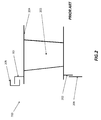
- a vane 200 in a "rocking vane" configuration, according to the prior art.
- a vane 200 includes an airfoil 203 mounted on a vane platform 204, which in turn comprises an outer single hook 201 fitted into a vane carrier receiving portion 205.
- Hook 201 provides outer axial, circumferential and radial support and translates axial, radial and circumferential vane loads into the vane carrier 205.
- vane 200 is supported axially at its inner diameter 202 by an inner structural component 208, which provides inner axial support.
- the component 202 is fitted into the vane carrier 205, as schematically indicated in the figure.
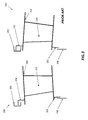
- vane 200 is pushed against the outer and inner axial vane carrier supports 205, 208 by the axial gas load applied to the airfoil 203. Due to different thermal expansion of the structural parts of a gas turbine engine in transient modes, the inner and the outer axial supports 205, 208 of the vane 200 will vary axially relative to each other. This will cause the vane 200 to tilt relative to the vane carrier 205 as shown in figure 3 . Moreover due to thermal stress in the vane itself, hook 201 may bend in any direction. In general, according to the teachings of the prior art, vane 200 provides a circumferential hook 201 having a cylindrical space on the outer side and a plane surface on the inner side.
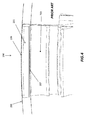
- the receiving groove in the vane carrier 205 provides outer and inner cylindrical surfaces which create a surface contact 206 at the outer side and an axial line contact 207 at the inner side, as shown in figure 4 .
- clearance between vane hook 201 and vane carrier 205 is typically kept as small as possible.
- a thermal deformation of the hook e.g. bending
- This will introduce high forces into the vane or the carrier, which results in a reduced lifetime.
- the object of the present invention is to solve the aforementioned technical problems by providing a gas turbine guide vane as substantially defined in independent claim 1.
- the present invention also provides a guide vane carrier as substantially defined in independent claim 8. Preferred embodiments are defined in correspondent dependent claims.
- the present solution provides a guide vane for a gas turbine which comprises a vane platform and a vane airfoil connected to the vane platform, wherein the vane platform comprises an elongated hook extending in a circumferential direction of the gas turbine and adapted to be housed in a guide vane carrier groove, wherein the guide vane further comprises a first and a second projecting pads located at distal ends of an outer side of the elongated hook and arranged to abut against the guide vane carrier groove, wherein the projecting pads have a rounded shape.
- the guide vane further comprises a third and a fourth projecting pads, located at distal ends of an inner side of the elongated hook and arranged to abut against the guide vane carrier, the inner side being opposite to the outer side of said elongated hook.
- the third and a fourth projecting pads have a substantially flat shape.
- the first and second projecting pads extend each one along a circumferential direction of the elongated hook for a length L which is selected in a range 5% - 25% of an entire circumferential length of the elongated hook.
- the length L is selected in a sub-range 10% - 15% of the entire circumferential length of the elongated hook.
- the length L is 12.5% of the entire circumferential length of the elongated hook.
- the elongated hook comprises a slot located on the outer side, the slot being adapted to receive a radial locking pin.
- a guide vane carrier which comprises a groove extending in a circumferential direction of the gas turbine and adapted to house a correspondent elongated hook of a vane platform of a guide vane, the groove comprising a first and a second contact portions located on an upper internal surface at respective upper distal ends thereof, the upper internal surface being opposed to an outer side of the elongated hook, wherein the first and a second contact portions have a substantially flat surface in a section view along an axial direction.
- the guide vane carrier further comprises a third and a forth contact portions located on a lower internal surface at lower distal ends thereof, the lower distal ends being opposed to the upper distal ends and the lower internal surface being opposed to an inner side of the elongated hook, and wherein the third and a forth contact portions have a substantially round surface. Therefore a novel concept has been invented providing only circumferential line contact or point contact between the guide vane and the guide vane carrier.
- the hook is designed thinner than the carrier groove in a middle part which enables bending of the hook without jamming.
- pads are located on inner and outer side to provide local contact with the carrier.
- the outer pads are shaped round in axial direction and are rotational-symmetric around engine centre line as well. This provides a linear contact of outer pads and carrier groove outer surface.
- the inner pads are flat and tangent to the carrier groove inner surface.
- the carrier groove inner surface however is shaped round in axial direction. This provides a point contact of the inner pad and carrier at the intersection point of tangents in axial and circumferential direction.
- the guide vane is allowed to tilt around the hook keeping defined contact at the circumferential ends of the hook even with a limited clearance at the contact location. Such limited clearance is required to minimize tilting of the vane in circumferential direction.
- a radial pin is engaged to a slot in the centre of the hook. Typically, the pin does not carry any axial or radial load, but only transfer circumferential load into the carrier.
- Guide vane 1 for a gas turbine in accordance with the present invention.
- Guide vane 1 comprises a vane platform, indicated with numeral reference 2, to which an airfoil 3 is connected.
- Vane platform 2 comprises an elongated hook 4 which extends along a circumferential direction C of the gas turbine.
- the vane platform 2 is adapted to be housed into a guide vane carrier (not shown) having a circumferential groove configured to receive the elongated hook 4.
- a plurality of guide vanes 1 are then inserted in sequence into the vane carrier groove along circumferential direction C, such to dispose a plurality of airfoils 3 along radial directions R and constitute a guide vane stage of the gas turbine.
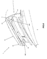
- the elongated hook 4 further comprises a first projecting pad 42 and a second projecting pad 43, which are located at respective distal ends 411 and 412 of an outer side 41 of the elongated hook 4.
- projecting pads 42 and 43 have a substantially rounded shape.
- the rounded shape of the projecting pads 42, 43 have a curvature radius of about 40 mm.
- elongated hook 4 from a different angle, showing an inner side 44 of the same which is opposite to the outer side 41.
- elongated hook 4 comprises a third projecting pad 45 and a fourth projecting pad 46, which are located on the inner side 44 of the elongated hook 4 and arranged to abut against the vane carrier groove (not shown).
- the projecting pads 45, 46 are located at respective distal ends 441, 442 of the inner side 44. Projecting pads 45, 46 have a substantially flat shape, and may be geometrically associated to the shape of a parallelepiped.
- carrier groove 5 comprises a first contact portion 52 and a second contact portion 53 which are located on respective distal ends 511 and 512 of the upper internal surface 51. Contact portions 52, 53 abut respectively against projecting pads 42 and 43 of the elongated hook 4.
- carrier groove 5 comprises a third contact portion 54 and a forth contact portion 55 which are located on respective distal ends 561 and 562 of the lower internal surface 56. Contact portions 54, 55 of the carrier groove 5 abut respectively against projecting pads 45 and 46.
- projecting pads 43 and 42 extend each one along the circumferential direction C for a length L which is selected in a range from 5% to 25% of an entire circumferential length H of the elongated hook 4. More preferably, the length L is selected among a sub-range 10% to 15% of the entire length H of the elongated hook 4. Even more preferably, length L is substantially equal to 12,5% of the entire length H.
- the elongated hook 4 comprises a slot 48 located on the outer side 41, which is adapted to receive a radial pin 60. Radial pin 60 is then inserted into a correspondent slot located in the upper internal surface of the carrier groove 5. Pin 60 has a locking function as it prevents the vane platform from sliding circumferentially along the carrier groove 5.
- contact portion 52 located on the upper internal surface 51 and in contact with rounded pad 42, has a substantially flat surface in a section view along an axial direction. More in particular, a curvature radius of the groove in correspondence of the contact portion 52 is constant along the axial direction.
- contact portion 54 located on the lower internal surface 56 and in contact with flat projecting pad 46, has a substantially rounded surface. Same geometry applies for contact surfaces 53 and 55 which abut respectively against projecting pads 43 and 46 (not shown in figure 9 ).
Landscapes
- Engineering & Computer Science (AREA)
- Mechanical Engineering (AREA)
- General Engineering & Computer Science (AREA)
- Architecture (AREA)
- Turbine Rotor Nozzle Sealing (AREA)
Description
- The present invention generally relates to a guide vane for a gas turbine, and more in particular it provides an innovative guide vane with improved flexibility leading to a reduction of stresses at the interface between the vane platform and the vane carrier.
- As well known, a standard configuration for a gas turbine envisages a plurality of vanes solidly connected to an outer casing, or vane carrier, which surrounds a rotating shaft guided by blades mounted thereon. In particular, each vane comprises an airfoil which is connected to a vane platform, which is in turn retained into the outer casing. As hot combustion gases pass through the casing to drive the rotating shaft, vanes experience high temperatures.
Generally a vane can be fixed to the outer casing at its outer diameter, in a cantilever fashion, or at its outer and inner diameters (the latter design known as rocking vane).
With reference tofigure 1 , it is schematically shown astator vane 100 in cantilevered design according to the state of the art, wherein thevane 100 includes anairfoil 103 mounted on avane platform 104 comprising a leadingedge hook 102 and atrailing edge hook 101, which are in turn mounted in avane carrier 105. Axial and circumferential fixation may be operated either on the leading ortrailing edge hooks - With reference to the following
figure 2 , it is shown astator vane 200 in a "rocking vane" configuration, according to the prior art. In this case, avane 200 includes anairfoil 203 mounted on avane platform 204, which in turn comprises an outersingle hook 201 fitted into a vanecarrier receiving portion 205. Hook 201 provides outer axial, circumferential and radial support and translates axial, radial and circumferential vane loads into thevane carrier 205.
Further,vane 200 is supported axially at itsinner diameter 202 by an innerstructural component 208, which provides inner axial support. Thecomponent 202 is fitted into thevane carrier 205, as schematically indicated in the figure. Thevane 200 is pushed against the outer and inner axial vane carrier supports 205, 208 by the axial gas load applied to theairfoil 203.
Due to different thermal expansion of the structural parts of a gas turbine engine in transient modes, the inner and the outeraxial supports vane 200 will vary axially relative to each other.
This will cause thevane 200 to tilt relative to thevane carrier 205 as shown infigure 3 . Moreover due to thermal stress in the vane itself,hook 201 may bend in any direction.
In general, according to the teachings of the prior art,vane 200 provides acircumferential hook 201 having a cylindrical space on the outer side and a plane surface on the inner side. The receiving groove in thevane carrier 205 provides outer and inner cylindrical surfaces which create asurface contact 206 at the outer side and anaxial line contact 207 at the inner side, as shown infigure 4 . In order to prevent undesired tilting of thehook 201 in circumferential direction within the receiving groove of thevane carrier 205, clearance betweenvane hook 201 andvane carrier 205 is typically kept as small as possible. Particularly for rocking-type of vanes, there are several drawbacks of the prior art.
Firstly a thermal deformation of the hook (e.g. bending) may jam the vane inside the groove. This will introduce high forces into the vane or the carrier, which results in a reduced lifetime.
A possible partial solution to such problem might be increasing the clearance, however this may allow for a considerable tilting of the vane in the circumferential direction. Moreover the vane shall be free to rotate around the hook about a few degrees (+/- 5° max.) to compensate relative outer and inner support movements which is not possible with an axial line contact and surface contact. - The object of the present invention is to solve the aforementioned technical problems by providing a gas turbine guide vane as substantially defined in
independent claim 1. - Furthermore, the present invention also provides a guide vane carrier as substantially defined in independent claim 8.
Preferred embodiments are defined in correspondent dependent claims. - According to preferred embodiments, which will be described in the following detailed description only for exemplary and non-limiting purposes, the present solution provides a guide vane for a gas turbine which comprises a vane platform and a vane airfoil connected to the vane platform, wherein the vane platform comprises an elongated hook extending in a circumferential direction of the gas turbine and adapted to be housed in a guide vane carrier groove, wherein the guide vane further comprises a first and a second projecting pads located at distal ends of an outer side of the elongated hook and arranged to abut against the guide vane carrier groove, wherein the projecting pads have a rounded shape.
- According to a preferred aspect of the invention, the guide vane further comprises a third and a fourth projecting pads, located at distal ends of an inner side of the elongated hook and arranged to abut against the guide vane carrier, the inner side being opposite to the outer side of said elongated hook.
- According to a preferred aspect of the invention, the third and a fourth projecting pads have a substantially flat shape.
- According to a preferred aspect of the invention, the first and second projecting pads extend each one along a circumferential direction of the elongated hook for a length L which is selected in a
range 5% - 25% of an entire circumferential length of the elongated hook. - According to a preferred aspect of the invention, the length L is selected in a sub-range 10% - 15% of the entire circumferential length of the elongated hook.
- According to a preferred aspect of the invention, the length L is 12.5% of the entire circumferential length of the elongated hook.
- According to a preferred aspect of the invention, the elongated hook comprises a slot located on the outer side, the slot being adapted to receive a radial locking pin.
- According to a further aspect of the invention, it is provided a guide vane carrier which comprises a groove extending in a circumferential direction of the gas turbine and adapted to house a correspondent elongated hook of a vane platform of a guide vane, the groove comprising a first and a second contact portions located on an upper internal surface at respective upper distal ends thereof, the upper internal surface being opposed to an outer side of the elongated hook, wherein the first and a second contact portions have a substantially flat surface in a section view along an axial direction.
- According to a preferred aspect of the invention, the guide vane carrier further comprises a third and a forth contact portions located on a lower internal surface at lower distal ends thereof, the lower distal ends being opposed to the upper distal ends and the lower internal surface being opposed to an inner side of the elongated hook, and wherein the third and a forth contact portions have a substantially round surface.
Therefore a novel concept has been invented providing only circumferential line contact or point contact between the guide vane and the guide vane carrier.
The hook is designed thinner than the carrier groove in a middle part which enables bending of the hook without jamming. At the two circumferential ends of the hook, pads are located on inner and outer side to provide local contact with the carrier.
The outer pads are shaped round in axial direction and are rotational-symmetric around engine centre line as well. This provides a linear contact of outer pads and carrier groove outer surface.
The inner pads are flat and tangent to the carrier groove inner surface. The carrier groove inner surface however is shaped round in axial direction. This provides a point contact of the inner pad and carrier at the intersection point of tangents in axial and circumferential direction. According to an aspect of the present invention, the guide vane is allowed to tilt around the hook keeping defined contact at the circumferential ends of the hook even with a limited clearance at the contact location. Such limited clearance is required to minimize tilting of the vane in circumferential direction.
For circumferential locking of the vane in the carrier a radial pin is engaged to a slot in the centre of the hook. Typically, the pin does not carry any axial or radial load, but only transfer circumferential load into the carrier. - The foregoing objects and many of the attendant advantages of this invention will become more readily appreciated as the same becomes better understood by reference to the following detailed description when taken in conjunction with the accompanying drawings, wherein:
-
Figures 1-4 show different kinds of guide vanes fitted into a correspondent guide vane carrier according to the prior art; -
Figures 5-6 show perspective views of a hook element of a guide vane according to the present invention; -
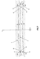
Figure 7-8 show a section view of a guide vane inserted into a guide vane carrier along a plane perpendicular to an axial direction of the gas turbine; -
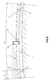
Figure 9 shows a detail of a hook element according to the present invention when inserted into the guide vane carrier. - With reference to
figure 5 , it is showed aguide vane 1 for a gas turbine in accordance with the present invention.Guide vane 1 comprises a vane platform, indicated withnumeral reference 2, to which anairfoil 3 is connected. Vaneplatform 2 comprises anelongated hook 4 which extends along a circumferential direction C of the gas turbine. Thevane platform 2 is adapted to be housed into a guide vane carrier (not shown) having a circumferential groove configured to receive theelongated hook 4. A plurality ofguide vanes 1 are then inserted in sequence into the vane carrier groove along circumferential direction C, such to dispose a plurality ofairfoils 3 along radial directions R and constitute a guide vane stage of the gas turbine. A plurality of stages is then formed along an axial direction of the gas turbine, indicated by axis A in the figure.
Theelongated hook 4 further comprises afirst projecting pad 42 and asecond projecting pad 43, which are located at respectivedistal ends outer side 41 of theelongated hook 4. According to an aspect of the invention, projectingpads
According to a preferred embodiment, the rounded shape of the projectingpads - Making now reference to following
figure 6 , it is shown theelongated hook 4 from a different angle, showing aninner side 44 of the same which is opposite to theouter side 41. In particular,elongated hook 4 comprises a third projectingpad 45 and a fourth projectingpad 46, which are located on theinner side 44 of theelongated hook 4 and arranged to abut against the vane carrier groove (not shown). The projectingpads inner side 44. Projectingpads - With reference to the following
figure 7 , it is shown a section along a radial plane of theelongated hook 4, extending along the circumferential direction C, inserted into a guidevane carrier groove 5. In the figure, it is clearly shown that theouter side 41 of theelongated hook 4 faces an upperinternal surface 51 of thegroove 5, whilst theinner side 44 of thehook 4 faces a lowerinternal surface 56 of thegroove 5.
Carrier groove 5 comprises afirst contact portion 52 and asecond contact portion 53 which are located on respective distal ends 511 and 512 of the upperinternal surface 51. Contactportions pads elongated hook 4. Similarly,carrier groove 5 comprises athird contact portion 54 and aforth contact portion 55 which are located on respective distal ends 561 and 562 of the lowerinternal surface 56. Contactportions carrier groove 5 abut respectively against projectingpads - With reference to next
figure 8 , it is still shown in the same view theelongated hook 4 inserted into the guidevane carrier groove 5. According to a preferred geometry, projectingpads elongated hook 4. More preferably, the length L is selected among a sub-range 10% to 15% of the entire length H of theelongated hook 4.
Even more preferably, length L is substantially equal to 12,5% of the entire length H.
Still with reference tofigure 8 , theelongated hook 4 comprises aslot 48 located on theouter side 41, which is adapted to receive aradial pin 60.Radial pin 60 is then inserted into a correspondent slot located in the upper internal surface of thecarrier groove 5.Pin 60 has a locking function as it prevents the vane platform from sliding circumferentially along thecarrier groove 5. - Making reference to last
figure 9 , it is shown a lateral section of thehook 4, inserted into thecarrier groove 5. In particular, the figure shows rounded projectingpad 42 which abuts againstcontact portion 52, and flat projectingpad 46 which abuts againstcontact portion 54.
Advantageously, in order to establish a linear circumferential contact between thegroove 5 and thehook 4,contact portion 52, located on the upperinternal surface 51 and in contact withrounded pad 42, has a substantially flat surface in a section view along an axial direction. More in particular, a curvature radius of the groove in correspondence of thecontact portion 52 is constant along the axial direction.
Moreover,contact portion 54, located on the lowerinternal surface 56 and in contact with flat projectingpad 46, has a substantially rounded surface.
Same geometry applies for contact surfaces 53 and 55 which abut respectively against projectingpads 43 and 46 (not shown infigure 9 ). - Although the present invention has been fully described in connection with preferred embodiments, it is evident that modifications may be introduced within the scope thereof, not considering the application to be limited by these embodiments, but by the content of the following claims.
Claims (11)
- Guide vane (1) for a gas turbine comprising a vane platform (2) and a vane airfoil (3) connected to said vane platform (2), wherein said vane platform (2) comprises an elongated hook (4) extending in a circumferential direction of the gas turbine and adapted to be housed in a guide vane carrier groove (5), wherein said guide vane (1) further comprises a first (42) and a second (43) projecting pads located at distal ends (411, 412) of an outer side (41) of said elongated hook (4) and arranged to abut against the guide vane carrier groove (5), said guide vane (1) being characterised in that said projecting pads (42, 43) have a rounded shape.
- Guide vane (1) according to the preceding claim, further comprising a third (45) and a fourth (46) projecting pads, located at distal ends (441, 442) of an inner side (44) of said elongated hook (4) and arranged to abut against the guide vane carrier (5), said inner side (44) being opposite to said outer side (41) of said elongated hook (4).
- Guide vane (1) according to the preceding claim, wherein said third (45) and a fourth (46) projecting pads have a substantially flat shape.
- Guide vane (1) according to any of the preceding claim, wherein said first (42) and second (43) projecting pads extend each one along a circumferential direction of said elongated hook (4) for a length L which is selected in a range 5% - 25% of an entire circumferential length of said elongated hook (4).
- Guide vane (1) according to any of the preceding claim, wherein the length L is selected in a sub-range 10% - 15% of the entire circumferential length of said elongated hook (4).
- Guide vane (1) according to the preceding claim, wherein the length L is 12,5% of the entire circumferential length of said elongated hook (4).
- Guide vane (1) according to any of the preceding claim, wherein said elongated hook (4) comprises a slot (48) located on said outer side (41), said slot (48) being adapted to receive a radial locking pin (60).
- Guide vane carrier (11) for a gas turbine, comprising a groove (5) extending in a circumferential direction of the gas turbine and adapted to house a correspondent elongated hook (4) of a vane platform (2) of a guide vane (1), said groove (5) comprising a first (52) and a second (53) contact portions located on an upper internal surface (51) at respective upper distal ends (511, 512) thereof, said upper internal surface (51) being opposed to an outer side (41) of the elongated hook (4), characterised in that said first (52) and a second (53) contact portions have a substantially flat surface.
- Guide vane carrier (11) according to the preceding claim, further comprising a third (54) and a forth (55) contact portions located on a lower internal surface (56) at lower distal ends (513, 514) thereof, said lower distal ends (513, 514) being opposed to said upper distal ends (511, 512) and said lower internal surface (56) being opposed to an inner side (44) of the elongated hook (4), characterised in that said third (54) and a forth (55) contact portions have a substantially round surface.
- Gas turbine, characterised in that it comprises a guide vane carrier (11) according to claims 8 or 9.
- Gas turbine, characterised in that it comprises a guide vane (1) according to any of claims 1-7.
Priority Applications (5)
| Application Number | Priority Date | Filing Date | Title |
|---|---|---|---|
| EP15186306.5A EP3147457B1 (en) | 2015-09-22 | 2015-09-22 | Gas turbine comprising a guide vane and a guide vane carrier |
| KR1020160120537A KR20170035334A (en) | 2015-09-22 | 2016-09-21 | Gas turbine vane |
| US15/272,165 US10731490B2 (en) | 2015-09-22 | 2016-09-21 | Gas turbine vane |
| JP2016184060A JP2017072130A (en) | 2015-09-22 | 2016-09-21 | Gas turbine vane |
| CN201610840038.9A CN106988785B (en) | 2015-09-22 | 2016-09-22 | Gas turbine guide vane |
Applications Claiming Priority (1)
| Application Number | Priority Date | Filing Date | Title |
|---|---|---|---|
| EP15186306.5A EP3147457B1 (en) | 2015-09-22 | 2015-09-22 | Gas turbine comprising a guide vane and a guide vane carrier |
Publications (2)
| Publication Number | Publication Date |
|---|---|
| EP3147457A1 true EP3147457A1 (en) | 2017-03-29 |
| EP3147457B1 EP3147457B1 (en) | 2019-01-30 |
Family
ID=54196850
Family Applications (1)
| Application Number | Title | Priority Date | Filing Date |
|---|---|---|---|
| EP15186306.5A Active EP3147457B1 (en) | 2015-09-22 | 2015-09-22 | Gas turbine comprising a guide vane and a guide vane carrier |
Country Status (5)
| Country | Link |
|---|---|
| US (1) | US10731490B2 (en) |
| EP (1) | EP3147457B1 (en) |
| JP (1) | JP2017072130A (en) |
| KR (1) | KR20170035334A (en) |
| CN (1) | CN106988785B (en) |
Cited By (1)
| Publication number | Priority date | Publication date | Assignee | Title |
|---|---|---|---|---|
| US11156115B2 (en) | 2018-06-28 | 2021-10-26 | MTU Aero Engines AG | Guide vane arrangement for turbomachine |
Families Citing this family (2)
| Publication number | Priority date | Publication date | Assignee | Title |
|---|---|---|---|---|
| KR102062594B1 (en) | 2018-05-11 | 2020-01-06 | 두산중공업 주식회사 | Vane carrier, compressor and gas turbine comprising the same |
| WO2025108581A1 (en) * | 2023-11-24 | 2025-05-30 | Nuovo Pignone Tecnologie - S.R.L. | An expander including inner rings supporting stationary blades |
Citations (4)
| Publication number | Priority date | Publication date | Assignee | Title |
|---|---|---|---|---|
| US5641267A (en) * | 1995-06-06 | 1997-06-24 | General Electric Company | Controlled leakage shroud panel |
| EP1653049A1 (en) * | 2004-10-26 | 2006-05-03 | ALSTOM Technology Ltd | Vane ring assembly for gas turbines and method to modify the same |
| EP2354460A1 (en) * | 2010-02-03 | 2011-08-10 | Alstom Technology Ltd | Turbine Guide Vane |
| US20120128481A1 (en) * | 2008-11-26 | 2012-05-24 | Snecma | Anti-wear device for the blades of a turbine distributor in an aeronautical turbine engine |
Family Cites Families (7)
| Publication number | Priority date | Publication date | Assignee | Title |
|---|---|---|---|---|
| US5205708A (en) * | 1992-02-07 | 1993-04-27 | General Electric Company | High pressure turbine component interference fit up |
| US5553999A (en) * | 1995-06-06 | 1996-09-10 | General Electric Company | Sealable turbine shroud hanger |
| FR2923527B1 (en) * | 2007-11-13 | 2013-12-27 | Snecma | STAGE OF TURBINE OR COMPRESSOR, IN PARTICULAR TURBOMACHINE |
| US8091371B2 (en) * | 2008-11-28 | 2012-01-10 | Pratt & Whitney Canada Corp. | Mid turbine frame for gas turbine engine |
| WO2014029728A1 (en) | 2012-08-20 | 2014-02-27 | Alstom Technology Ltd | Internally cooled airfoil for a rotary machine |
| EP2886801B1 (en) | 2013-12-20 | 2019-04-24 | Ansaldo Energia IP UK Limited | Seal system for a gas turbine and corresponding gas turbine |
| US10100649B2 (en) * | 2015-03-31 | 2018-10-16 | Rolls-Royce North American Technologies Inc. | Compliant rail hanger |
-
2015
- 2015-09-22 EP EP15186306.5A patent/EP3147457B1/en active Active
-
2016
- 2016-09-21 KR KR1020160120537A patent/KR20170035334A/en not_active Withdrawn
- 2016-09-21 JP JP2016184060A patent/JP2017072130A/en active Pending
- 2016-09-21 US US15/272,165 patent/US10731490B2/en active Active
- 2016-09-22 CN CN201610840038.9A patent/CN106988785B/en active Active
Patent Citations (4)
| Publication number | Priority date | Publication date | Assignee | Title |
|---|---|---|---|---|
| US5641267A (en) * | 1995-06-06 | 1997-06-24 | General Electric Company | Controlled leakage shroud panel |
| EP1653049A1 (en) * | 2004-10-26 | 2006-05-03 | ALSTOM Technology Ltd | Vane ring assembly for gas turbines and method to modify the same |
| US20120128481A1 (en) * | 2008-11-26 | 2012-05-24 | Snecma | Anti-wear device for the blades of a turbine distributor in an aeronautical turbine engine |
| EP2354460A1 (en) * | 2010-02-03 | 2011-08-10 | Alstom Technology Ltd | Turbine Guide Vane |
Cited By (1)
| Publication number | Priority date | Publication date | Assignee | Title |
|---|---|---|---|---|
| US11156115B2 (en) | 2018-06-28 | 2021-10-26 | MTU Aero Engines AG | Guide vane arrangement for turbomachine |
Also Published As
| Publication number | Publication date |
|---|---|
| CN106988785A (en) | 2017-07-28 |
| CN106988785B (en) | 2021-07-23 |
| JP2017072130A (en) | 2017-04-13 |
| US10731490B2 (en) | 2020-08-04 |
| US20170081969A1 (en) | 2017-03-23 |
| KR20170035334A (en) | 2017-03-30 |
| EP3147457B1 (en) | 2019-01-30 |
Similar Documents
| Publication | Publication Date | Title |
|---|---|---|
| CN106368742B (en) | Method and system for butting ceramic matrix composite components to metal components | |
| US8540488B2 (en) | Turbine blade damping device with controlled loading | |
| JP6106021B2 (en) | Turbine assembly | |
| US10731490B2 (en) | Gas turbine vane | |
| US20070014668A1 (en) | Seal and locking plate for turbine rotor assembly between turbine blade and turbine vane | |
| US20180112555A1 (en) | Damped guide vane bearing arrangement | |
| JP4335771B2 (en) | Turbine blades and turbine equipment | |
| EP2951395B1 (en) | Turbomachine rotor blade, turbomachine rotor disc, turbomachine rotor, and gas turbine engine with different root and slot contact face angles | |
| US7708529B2 (en) | Rotor of a turbo engine, e.g., a gas turbine rotor | |
| EP3608522B1 (en) | Turbocharger | |
| CN108368874A (en) | Film bearing | |
| US20120034086A1 (en) | Swing axial entry dovetail for steam turbine buckets | |
| CN104704244A (en) | Turbomachine casing and impeller | |
| US20140246835A1 (en) | Component | |
| CN102459819B (en) | A rotor blade for an axial flow turbomachine and mounting for such a rotor blade | |
| US7140841B2 (en) | Rotor blade connecting arrangement for a turbomachine | |
| KR20150050472A (en) | Methods and systems for securing turbine nozzles | |
| US20170241279A1 (en) | Guide vane segment for a turbomachine | |
| US20170159467A1 (en) | Guide vane ring casing for a turbomachine and turbomachine having a guide vane ring casing | |
| US11525368B2 (en) | Turbine guide apparatus | |
| EP3628822B1 (en) | Sealing systems | |
| FR3041714A1 (en) | TURBOMACHINE COMPRESSOR, ESPECIALLY AIRCRAFT TURBOPROPULSER OR AIRCRAFT TURBINEACTOR | |
| CN113227540A (en) | Rotor blade of rotating body and disk | |
| US9964192B2 (en) | Bi-directional hydrodynamic thrust washer for a torque converter | |
| JP2017072047A (en) | Turbine blade assembly and steam turbine |
Legal Events
| Date | Code | Title | Description |
|---|---|---|---|
| PUAI | Public reference made under article 153(3) epc to a published international application that has entered the european phase |
Free format text: ORIGINAL CODE: 0009012 |
|
| STAA | Information on the status of an ep patent application or granted ep patent |
Free format text: STATUS: THE APPLICATION HAS BEEN PUBLISHED |
|
| AK | Designated contracting states |
Kind code of ref document: A1 Designated state(s): AL AT BE BG CH CY CZ DE DK EE ES FI FR GB GR HR HU IE IS IT LI LT LU LV MC MK MT NL NO PL PT RO RS SE SI SK SM TR |
|
| AX | Request for extension of the european patent |
Extension state: BA ME |
|
| RAP1 | Party data changed (applicant data changed or rights of an application transferred) |
Owner name: ANSALDO ENERGIA SWITZERLAND AG |
|
| STAA | Information on the status of an ep patent application or granted ep patent |
Free format text: STATUS: REQUEST FOR EXAMINATION WAS MADE |
|
| 17P | Request for examination filed |
Effective date: 20170927 |
|
| RBV | Designated contracting states (corrected) |
Designated state(s): AL AT BE BG CH CY CZ DE DK EE ES FI FR GB GR HR HU IE IS IT LI LT LU LV MC MK MT NL NO PL PT RO RS SE SI SK SM TR |
|
| GRAP | Despatch of communication of intention to grant a patent |
Free format text: ORIGINAL CODE: EPIDOSNIGR1 |
|
| STAA | Information on the status of an ep patent application or granted ep patent |
Free format text: STATUS: GRANT OF PATENT IS INTENDED |
|
| INTG | Intention to grant announced |
Effective date: 20180906 |
|
| GRAS | Grant fee paid |
Free format text: ORIGINAL CODE: EPIDOSNIGR3 |
|
| GRAA | (expected) grant |
Free format text: ORIGINAL CODE: 0009210 |
|
| STAA | Information on the status of an ep patent application or granted ep patent |
Free format text: STATUS: THE PATENT HAS BEEN GRANTED |
|
| AK | Designated contracting states |
Kind code of ref document: B1 Designated state(s): AL AT BE BG CH CY CZ DE DK EE ES FI FR GB GR HR HU IE IS IT LI LT LU LV MC MK MT NL NO PL PT RO RS SE SI SK SM TR |
|
| REG | Reference to a national code |
Ref country code: GB Ref legal event code: FG4D |
|
| REG | Reference to a national code |
Ref country code: CH Ref legal event code: EP |
|
| REG | Reference to a national code |
Ref country code: AT Ref legal event code: REF Ref document number: 1093435 Country of ref document: AT Kind code of ref document: T Effective date: 20190215 |
|
| REG | Reference to a national code |
Ref country code: IE Ref legal event code: FG4D |
|
| REG | Reference to a national code |
Ref country code: DE Ref legal event code: R096 Ref document number: 602015023918 Country of ref document: DE |
|
| REG | Reference to a national code |
Ref country code: LT Ref legal event code: MG4D |
|
| REG | Reference to a national code |
Ref country code: NL Ref legal event code: MP Effective date: 20190130 |
|
| PG25 | Lapsed in a contracting state [announced via postgrant information from national office to epo] |
Ref country code: ES Free format text: LAPSE BECAUSE OF FAILURE TO SUBMIT A TRANSLATION OF THE DESCRIPTION OR TO PAY THE FEE WITHIN THE PRESCRIBED TIME-LIMIT Effective date: 20190130 Ref country code: NL Free format text: LAPSE BECAUSE OF FAILURE TO SUBMIT A TRANSLATION OF THE DESCRIPTION OR TO PAY THE FEE WITHIN THE PRESCRIBED TIME-LIMIT Effective date: 20190130 Ref country code: LT Free format text: LAPSE BECAUSE OF FAILURE TO SUBMIT A TRANSLATION OF THE DESCRIPTION OR TO PAY THE FEE WITHIN THE PRESCRIBED TIME-LIMIT Effective date: 20190130 Ref country code: PL Free format text: LAPSE BECAUSE OF FAILURE TO SUBMIT A TRANSLATION OF THE DESCRIPTION OR TO PAY THE FEE WITHIN THE PRESCRIBED TIME-LIMIT Effective date: 20190130 Ref country code: PT Free format text: LAPSE BECAUSE OF FAILURE TO SUBMIT A TRANSLATION OF THE DESCRIPTION OR TO PAY THE FEE WITHIN THE PRESCRIBED TIME-LIMIT Effective date: 20190530 Ref country code: NO Free format text: LAPSE BECAUSE OF FAILURE TO SUBMIT A TRANSLATION OF THE DESCRIPTION OR TO PAY THE FEE WITHIN THE PRESCRIBED TIME-LIMIT Effective date: 20190430 Ref country code: FI Free format text: LAPSE BECAUSE OF FAILURE TO SUBMIT A TRANSLATION OF THE DESCRIPTION OR TO PAY THE FEE WITHIN THE PRESCRIBED TIME-LIMIT Effective date: 20190130 Ref country code: SE Free format text: LAPSE BECAUSE OF FAILURE TO SUBMIT A TRANSLATION OF THE DESCRIPTION OR TO PAY THE FEE WITHIN THE PRESCRIBED TIME-LIMIT Effective date: 20190130 |
|
| REG | Reference to a national code |
Ref country code: AT Ref legal event code: MK05 Ref document number: 1093435 Country of ref document: AT Kind code of ref document: T Effective date: 20190130 |
|
| PG25 | Lapsed in a contracting state [announced via postgrant information from national office to epo] |
Ref country code: RS Free format text: LAPSE BECAUSE OF FAILURE TO SUBMIT A TRANSLATION OF THE DESCRIPTION OR TO PAY THE FEE WITHIN THE PRESCRIBED TIME-LIMIT Effective date: 20190130 Ref country code: HR Free format text: LAPSE BECAUSE OF FAILURE TO SUBMIT A TRANSLATION OF THE DESCRIPTION OR TO PAY THE FEE WITHIN THE PRESCRIBED TIME-LIMIT Effective date: 20190130 Ref country code: BG Free format text: LAPSE BECAUSE OF FAILURE TO SUBMIT A TRANSLATION OF THE DESCRIPTION OR TO PAY THE FEE WITHIN THE PRESCRIBED TIME-LIMIT Effective date: 20190430 Ref country code: LV Free format text: LAPSE BECAUSE OF FAILURE TO SUBMIT A TRANSLATION OF THE DESCRIPTION OR TO PAY THE FEE WITHIN THE PRESCRIBED TIME-LIMIT Effective date: 20190130 Ref country code: IS Free format text: LAPSE BECAUSE OF FAILURE TO SUBMIT A TRANSLATION OF THE DESCRIPTION OR TO PAY THE FEE WITHIN THE PRESCRIBED TIME-LIMIT Effective date: 20190530 Ref country code: GR Free format text: LAPSE BECAUSE OF FAILURE TO SUBMIT A TRANSLATION OF THE DESCRIPTION OR TO PAY THE FEE WITHIN THE PRESCRIBED TIME-LIMIT Effective date: 20190501 |
|
| PG25 | Lapsed in a contracting state [announced via postgrant information from national office to epo] |
Ref country code: SK Free format text: LAPSE BECAUSE OF FAILURE TO SUBMIT A TRANSLATION OF THE DESCRIPTION OR TO PAY THE FEE WITHIN THE PRESCRIBED TIME-LIMIT Effective date: 20190130 Ref country code: RO Free format text: LAPSE BECAUSE OF FAILURE TO SUBMIT A TRANSLATION OF THE DESCRIPTION OR TO PAY THE FEE WITHIN THE PRESCRIBED TIME-LIMIT Effective date: 20190130 Ref country code: CZ Free format text: LAPSE BECAUSE OF FAILURE TO SUBMIT A TRANSLATION OF THE DESCRIPTION OR TO PAY THE FEE WITHIN THE PRESCRIBED TIME-LIMIT Effective date: 20190130 Ref country code: AL Free format text: LAPSE BECAUSE OF FAILURE TO SUBMIT A TRANSLATION OF THE DESCRIPTION OR TO PAY THE FEE WITHIN THE PRESCRIBED TIME-LIMIT Effective date: 20190130 Ref country code: DK Free format text: LAPSE BECAUSE OF FAILURE TO SUBMIT A TRANSLATION OF THE DESCRIPTION OR TO PAY THE FEE WITHIN THE PRESCRIBED TIME-LIMIT Effective date: 20190130 Ref country code: EE Free format text: LAPSE BECAUSE OF FAILURE TO SUBMIT A TRANSLATION OF THE DESCRIPTION OR TO PAY THE FEE WITHIN THE PRESCRIBED TIME-LIMIT Effective date: 20190130 Ref country code: IT Free format text: LAPSE BECAUSE OF FAILURE TO SUBMIT A TRANSLATION OF THE DESCRIPTION OR TO PAY THE FEE WITHIN THE PRESCRIBED TIME-LIMIT Effective date: 20190130 |
|
| REG | Reference to a national code |
Ref country code: DE Ref legal event code: R097 Ref document number: 602015023918 Country of ref document: DE |
|
| PG25 | Lapsed in a contracting state [announced via postgrant information from national office to epo] |
Ref country code: SM Free format text: LAPSE BECAUSE OF FAILURE TO SUBMIT A TRANSLATION OF THE DESCRIPTION OR TO PAY THE FEE WITHIN THE PRESCRIBED TIME-LIMIT Effective date: 20190130 |
|
| PLBE | No opposition filed within time limit |
Free format text: ORIGINAL CODE: 0009261 |
|
| STAA | Information on the status of an ep patent application or granted ep patent |
Free format text: STATUS: NO OPPOSITION FILED WITHIN TIME LIMIT |
|
| PG25 | Lapsed in a contracting state [announced via postgrant information from national office to epo] |
Ref country code: AT Free format text: LAPSE BECAUSE OF FAILURE TO SUBMIT A TRANSLATION OF THE DESCRIPTION OR TO PAY THE FEE WITHIN THE PRESCRIBED TIME-LIMIT Effective date: 20190130 |
|
| 26N | No opposition filed |
Effective date: 20191031 |
|
| PG25 | Lapsed in a contracting state [announced via postgrant information from national office to epo] |
Ref country code: SI Free format text: LAPSE BECAUSE OF FAILURE TO SUBMIT A TRANSLATION OF THE DESCRIPTION OR TO PAY THE FEE WITHIN THE PRESCRIBED TIME-LIMIT Effective date: 20190130 |
|
| PG25 | Lapsed in a contracting state [announced via postgrant information from national office to epo] |
Ref country code: TR Free format text: LAPSE BECAUSE OF FAILURE TO SUBMIT A TRANSLATION OF THE DESCRIPTION OR TO PAY THE FEE WITHIN THE PRESCRIBED TIME-LIMIT Effective date: 20190130 |
|
| PG25 | Lapsed in a contracting state [announced via postgrant information from national office to epo] |
Ref country code: MC Free format text: LAPSE BECAUSE OF FAILURE TO SUBMIT A TRANSLATION OF THE DESCRIPTION OR TO PAY THE FEE WITHIN THE PRESCRIBED TIME-LIMIT Effective date: 20190130 |
|
| REG | Reference to a national code |
Ref country code: CH Ref legal event code: PL |
|
| PG25 | Lapsed in a contracting state [announced via postgrant information from national office to epo] |
Ref country code: IE Free format text: LAPSE BECAUSE OF NON-PAYMENT OF DUE FEES Effective date: 20190922 Ref country code: LU Free format text: LAPSE BECAUSE OF NON-PAYMENT OF DUE FEES Effective date: 20190922 Ref country code: CH Free format text: LAPSE BECAUSE OF NON-PAYMENT OF DUE FEES Effective date: 20190930 Ref country code: LI Free format text: LAPSE BECAUSE OF NON-PAYMENT OF DUE FEES Effective date: 20190930 |
|
| REG | Reference to a national code |
Ref country code: BE Ref legal event code: MM Effective date: 20190930 |
|
| PG25 | Lapsed in a contracting state [announced via postgrant information from national office to epo] |
Ref country code: BE Free format text: LAPSE BECAUSE OF NON-PAYMENT OF DUE FEES Effective date: 20190930 |
|
| GBPC | Gb: european patent ceased through non-payment of renewal fee |
Effective date: 20190922 |
|
| PG25 | Lapsed in a contracting state [announced via postgrant information from national office to epo] |
Ref country code: FR Free format text: LAPSE BECAUSE OF NON-PAYMENT OF DUE FEES Effective date: 20190930 Ref country code: GB Free format text: LAPSE BECAUSE OF NON-PAYMENT OF DUE FEES Effective date: 20190922 |
|
| PG25 | Lapsed in a contracting state [announced via postgrant information from national office to epo] |
Ref country code: CY Free format text: LAPSE BECAUSE OF FAILURE TO SUBMIT A TRANSLATION OF THE DESCRIPTION OR TO PAY THE FEE WITHIN THE PRESCRIBED TIME-LIMIT Effective date: 20190130 |
|
| PG25 | Lapsed in a contracting state [announced via postgrant information from national office to epo] |
Ref country code: HU Free format text: LAPSE BECAUSE OF FAILURE TO SUBMIT A TRANSLATION OF THE DESCRIPTION OR TO PAY THE FEE WITHIN THE PRESCRIBED TIME-LIMIT; INVALID AB INITIO Effective date: 20150922 Ref country code: MT Free format text: LAPSE BECAUSE OF FAILURE TO SUBMIT A TRANSLATION OF THE DESCRIPTION OR TO PAY THE FEE WITHIN THE PRESCRIBED TIME-LIMIT Effective date: 20190130 |
|
| PG25 | Lapsed in a contracting state [announced via postgrant information from national office to epo] |
Ref country code: MK Free format text: LAPSE BECAUSE OF FAILURE TO SUBMIT A TRANSLATION OF THE DESCRIPTION OR TO PAY THE FEE WITHIN THE PRESCRIBED TIME-LIMIT Effective date: 20190130 |
|
| P01 | Opt-out of the competence of the unified patent court (upc) registered |
Effective date: 20240430 |
|
| PGFP | Annual fee paid to national office [announced via postgrant information from national office to epo] |
Ref country code: DE Payment date: 20250919 Year of fee payment: 11 |