EP3147221A1 - Aircraft nitrogen generation and oxygen distribution - Google Patents
Aircraft nitrogen generation and oxygen distribution Download PDFInfo
- Publication number
- EP3147221A1 EP3147221A1 EP16174099.8A EP16174099A EP3147221A1 EP 3147221 A1 EP3147221 A1 EP 3147221A1 EP 16174099 A EP16174099 A EP 16174099A EP 3147221 A1 EP3147221 A1 EP 3147221A1
- Authority
- EP
- European Patent Office
- Prior art keywords
- oxygen
- oxygen distribution
- enriched air
- aircraft
- nitrogen generation
- Prior art date
- Legal status (The legal status is an assumption and is not a legal conclusion. Google has not performed a legal analysis and makes no representation as to the accuracy of the status listed.)
- Granted
Links
Images


Classifications
-
- B—PERFORMING OPERATIONS; TRANSPORTING
- B64—AIRCRAFT; AVIATION; COSMONAUTICS
- B64D—EQUIPMENT FOR FITTING IN OR TO AIRCRAFT; FLIGHT SUITS; PARACHUTES; ARRANGEMENT OR MOUNTING OF POWER PLANTS OR PROPULSION TRANSMISSIONS IN AIRCRAFT
- B64D33/00—Arrangement in aircraft of power plant parts or auxiliaries not otherwise provided for
-
- B—PERFORMING OPERATIONS; TRANSPORTING
- B64—AIRCRAFT; AVIATION; COSMONAUTICS
- B64D—EQUIPMENT FOR FITTING IN OR TO AIRCRAFT; FLIGHT SUITS; PARACHUTES; ARRANGEMENT OR MOUNTING OF POWER PLANTS OR PROPULSION TRANSMISSIONS IN AIRCRAFT
- B64D33/00—Arrangement in aircraft of power plant parts or auxiliaries not otherwise provided for
- B64D33/02—Arrangement in aircraft of power plant parts or auxiliaries not otherwise provided for of combustion air intakes
-
- B—PERFORMING OPERATIONS; TRANSPORTING
- B64—AIRCRAFT; AVIATION; COSMONAUTICS
- B64D—EQUIPMENT FOR FITTING IN OR TO AIRCRAFT; FLIGHT SUITS; PARACHUTES; ARRANGEMENT OR MOUNTING OF POWER PLANTS OR PROPULSION TRANSMISSIONS IN AIRCRAFT
- B64D37/00—Arrangements in connection with fuel supply for power plant
- B64D37/32—Safety measures not otherwise provided for, e.g. preventing explosive conditions
-
- B—PERFORMING OPERATIONS; TRANSPORTING
- B64—AIRCRAFT; AVIATION; COSMONAUTICS
- B64D—EQUIPMENT FOR FITTING IN OR TO AIRCRAFT; FLIGHT SUITS; PARACHUTES; ARRANGEMENT OR MOUNTING OF POWER PLANTS OR PROPULSION TRANSMISSIONS IN AIRCRAFT
- B64D13/00—Arrangements or adaptations of air-treatment apparatus for aircraft crew or passengers, or freight space
- B64D13/02—Arrangements or adaptations of air-treatment apparatus for aircraft crew or passengers, or freight space the air being pressurised
-
- B—PERFORMING OPERATIONS; TRANSPORTING
- B64—AIRCRAFT; AVIATION; COSMONAUTICS
- B64D—EQUIPMENT FOR FITTING IN OR TO AIRCRAFT; FLIGHT SUITS; PARACHUTES; ARRANGEMENT OR MOUNTING OF POWER PLANTS OR PROPULSION TRANSMISSIONS IN AIRCRAFT
- B64D13/00—Arrangements or adaptations of air-treatment apparatus for aircraft crew or passengers, or freight space
- B64D13/06—Arrangements or adaptations of air-treatment apparatus for aircraft crew or passengers, or freight space the air being conditioned
-
- B—PERFORMING OPERATIONS; TRANSPORTING
- B64—AIRCRAFT; AVIATION; COSMONAUTICS
- B64D—EQUIPMENT FOR FITTING IN OR TO AIRCRAFT; FLIGHT SUITS; PARACHUTES; ARRANGEMENT OR MOUNTING OF POWER PLANTS OR PROPULSION TRANSMISSIONS IN AIRCRAFT
- B64D37/00—Arrangements in connection with fuel supply for power plant
- B64D37/34—Conditioning fuel, e.g. heating
-
- B—PERFORMING OPERATIONS; TRANSPORTING
- B01—PHYSICAL OR CHEMICAL PROCESSES OR APPARATUS IN GENERAL
- B01D—SEPARATION
- B01D53/00—Separation of gases or vapours; Recovering vapours of volatile solvents from gases; Chemical or biological purification of waste gases, e.g. engine exhaust gases, smoke, fumes, flue gases, aerosols
-
- B—PERFORMING OPERATIONS; TRANSPORTING
- B64—AIRCRAFT; AVIATION; COSMONAUTICS
- B64D—EQUIPMENT FOR FITTING IN OR TO AIRCRAFT; FLIGHT SUITS; PARACHUTES; ARRANGEMENT OR MOUNTING OF POWER PLANTS OR PROPULSION TRANSMISSIONS IN AIRCRAFT
- B64D13/00—Arrangements or adaptations of air-treatment apparatus for aircraft crew or passengers, or freight space
- B64D13/06—Arrangements or adaptations of air-treatment apparatus for aircraft crew or passengers, or freight space the air being conditioned
- B64D2013/0603—Environmental Control Systems
- B64D2013/0677—Environmental Control Systems comprising on board oxygen generator systems
Definitions
- Aircraft often utilize a nitrogen generation system (NGS), or On Board Inert Gas Generation System, to provide nitrogen enriched air to the fuel tanks in order to render the tanks inert for safety purposes.
- NGS nitrogen generation system
- a byproduct of an NGS is oxygen enriched air. This excess oxygen enriched air is commonly expelled to the ambient environment outside of the aircraft.
- a nitrogen generation and oxygen distribution system includes an NGS and an oxygen distribution processor coupled to the NGS.
- the NGS operates to create nitrogen enriched air as the primary product and oxygen enriched air as a secondary product, and to route the nitrogen enriched air to a fuel tank of an aircraft.
- the oxygen distribution processor is operative to determine a number of flight parameters, and from those parameters, select an oxygen distribution configuration associated with the NGS.
- the oxygen distribution processor routes the oxygen enriched air from the NGS to an ambient environment surrounding the aircraft.
- the oxygen distribution processor routes the oxygen enriched air from the NGS to an engine or engines of the aircraft.
- a nitrogen generation and oxygen distribution computer system includes an oxygen distribution processor coupled to an NGS of an aircraft.
- the computer system further includes an oxygen distribution application that, when executed by the oxygen distribution processor, causes the computer system to determine a number of flight parameters, and from those parameters, select an oxygen distribution configuration associated with the NGS.
- the oxygen enriched air is routed from the NGS to an ambient environment surrounding the aircraft.
- the oxygen enriched air is routed from the NGS to an engine of the aircraft.
- a computer-implemented method for distributing oxygen enriched air generated as a secondary product by an NGS of an aircraft includes determining a number of flight parameters and selecting an oxygen distribution configuration associated with the NGS from the flight parameters. In response to selecting a first oxygen distribution configuration, the oxygen enriched air is routed from the NGS to an ambient environment surrounding the aircraft. In response to selecting a second oxygen distribution configuration, the oxygen enriched air is routed from the NGS to an engine of the aircraft.
- NGSs nitrogen generation systems
- Conventional NGSs produce oxygen enriched air as a secondary product, or byproduct, of the nitrogen production process. This oxygen enriched air is then vented overboard to the ambient atmosphere.
- the oxygen enriched air produced by the NGS of an aircraft which is typically vented to the ambient atmosphere, may be routed to one or more engines of the aircraft.
- An increased quantity of oxygen in the air entering the combustion chamber of the engine can increase the efficiency of the combustion process.
- an oxygen distribution processor makes dynamic routing decisions with respect to the oxygen enriched air produced by the NGS, directing the oxygen enriched air to the ambient environment, to one or more aircraft engines, or blocking the production of the oxygen enriched air altogether.
- the dynamic routing decisions are based on any number of flight parameters received or determined in real time. In doing so, the NGS operation and corresponding products may be utilized to not only provide an inert environment within the aircraft fuel tanks, but also to increase the operational efficiency of the aircraft engines.
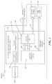
- FIGURE 1 shows a block diagram of nitrogen generation and oxygen distribution system 102 of an aircraft 100.
- the nitrogen generation and oxygen distribution system 102 includes the nitrogen generation system (NGS) 104 that produces the nitrogen enriched air 106 for the one or more fuel tanks 108 of the aircraft 100.
- the various components and corresponding operations of the NGS 104 are well known and are not material to this disclosure.
- the NGS 104 of the nitrogen generation and oxygen distribution system 102 is not merely a stand-alone system that produces nitrogen enriched air 106 per the conventional application of the NGS in a typical aircraft. Rather, the NGS 104 of the nitrogen generation and oxygen distribution system 102 is communicatively coupled to an oxygen distribution processor 116 and oxygen distribution valve 118.
- the oxygen distribution processor 116 is further communicatively coupled to a sensor suite 120 of the aircraft 100.
- the oxygen distribution processor 116 receives data from the sensor suite 120 of the aircraft 100 and interprets the data to determine where to distribute the oxygen enriched air 110 that is created as a secondary product by the NGS 104.
- the sensor suite 120 may include any number and type of sensors that alone or in combination may provide data interpreted by the oxygen distribution processor 116 to determine various flight parameters 119.
- the flight parameters 119 may include real-time aircraft or environmental characteristics, including, but not limited to, aircraft altitude, ambient pressure, ambient temperature, engine combustion chamber temperature, fuel flow, airflow into an engine, engine speed, and engine warnings. These flight parameters 119, as well as any additional or alternative environmental and/or aircraft data, may be interpreted to determine a phase of flight of the aircraft 100.
- the nitrogen generation and oxygen distribution system 102 will maintain maximum performance of the NGS 104 for fuel tank inerting purposes during selected flight phases. During these maximum NGS performance phases of flight, the nitrogen generation and oxygen distribution system 102 ensures that the oxygen enriched air 110 from the NGS 104 is vented to the ambient environment 112. Venting the oxygen enriched air 110 to the ambient environment 112 provides a pressure differential that facilitates the process of providing nitrogen enriched air 106 to the fuel tank 108.
- the performance of the NGS 104 may be reduced without a significant consequence since the fuel tank 108 is inert and the NGS 104 is able to provide a reduced quantity of nitrogen enriched air 106 as fuel is consumed to sustain the inert status of the fuel tank 108.
- embodiments described herein provide for the oxygen distribution processor 116 to route the oxygen enriched air 110 from the NGS 104 to the aircraft engine 114.
- the aircraft engine 114 will be referred to in the singular form; however, it should be appreciated that the nitrogen generation and oxygen distribution system 102 may direct oxygen enriched air 110 to any number of aircraft engines 114.
- the flight parameters 119 may additionally include performance criteria associated with the NGS 104.
- the performance criteria may include an operational state of the NGS 104, such as whether or not the NGS 104 is operating without fault or if a compressor acting on the output of the NGS 104 is operational.
- the oxygen distribution processor 116 will close the oxygen distribution valve 118 to prevent backflow into the NGS 104. This process will be illustrated and discussed further below.
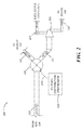
- FIGURE 2 shows a schematic diagram 200 illustrating the flow of oxygen enriched air 110 through an oxygen distribution valve 118 in an aircraft 100 utilizing a pneumatic compressor 202.
- the oxygen enriched air 110 flows from the NGS 104 to the oxygen distribution valve 118.
- the oxygen distribution valve 118 may be any type of suitable valve that is controllable via a signal sent by the oxygen distribution processor 116 to selectively provide one output path for the oxygen enriched air 110 while closing off other potential output paths. Examples include, but are not limited to, a butterfly valve, a gate valve, a ball valve, a globe valve, or any other suitable valve.
- the oxygen distribution valve 118 is configured to receive an oxygen distribution command 206 from the oxygen distribution processor 116 and to position the valve accordingly in one of three potential positions. Specifically, the oxygen distribution processor 116 controls the oxygen distribution valve 118 (1) to prevent any distribution of the oxygen enriched air 110, (2) to direct the oxygen enriched air 110 to the ambient environment 112, or (3) to direct the oxygen enriched air 110 to the aircraft engine 114.
- the oxygen enriched air 110 flowing to the aircraft engine 114 flows through the pneumatic compressor 202 in order to provide the oxygen enriched air 110 to a high pressure area within the aircraft engine 114.
- the pneumatic compressor 202 is powered by bleed air from the aircraft engine 114, which flows through a compressor shutoff valve 204.
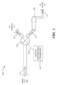
- FIGURE 3 shows a similar schematic diagram 300 as shown in FIGURE 2 ; however, the compressor used in this example is an electrically driven compressor 302, which does not require the bleed air and corresponding compressor shutoff valve. It should be understood that while FIGURES 2 and 3 show pneumatically and electrically driven compressors, respectively, the disclosure herein is not limited to any particular type of compressor.
- the oxygen enriched air 110 may be distributed to alternative locations in addition to or alternatively to the aircraft engine 114.
- the oxygen enriched air 110 may be directed to the aircraft cabin for pressurization purposes.
- the oxygen distribution processor 116 may determine the routing location for the oxygen enriched air 110 based on any number of pre-programmed factors or prioritizations.
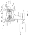
- FIGURE 4 shows a block diagram and cross-sectional view of a nitrogen generation and oxygen distribution system and aircraft engine 114 to illustrate oxygen distribution to the aircraft engine 114 according to various embodiments described herein.
- the aircraft engine 114 has been annotated to show various engine stages.
- the aircraft engine 114 includes a fan 402, a compressor section 404, a combustion chamber 406, a high-pressure turbine 408, a low-pressure turbine 410, and a nozzle 412.
- the oxygen enriched air 110 from the NGS 104 is injected or routed directly into the combustion chamber 406.
- a compressor 420 may be used to provide the oxygen enriched air 110 at a suitable pressure.
- the compressor 420 may be the pneumatic compressor 202 or the electrically driven compressor 302.
- the oxygen enriched air 110 may be routed to the compressor section 404 upstream of the combustion chamber 406, as indicated by the broken arrow.
- the oxygen enriched air 110 should be utilized within the combustion chamber 406. Introducing the oxygen enriched air 110 farther upstream from the compressor section 404 may result in a portion of the oxygen enriched air 110 being bypassed around the combustion chamber 406, reducing the effects of the oxygen enriched air 110 distribution from the nitrogen generation and oxygen distribution system 102 into the aircraft engine 114.
- the oxygen enriched air of approximately 25-40% oxygen 110 entering the combustion chamber 406 from the nitrogen generation and oxygen distribution system 102 mixes with the air entering the combustion chamber 406 from the fan 402 of the aircraft engine 114 to produce a quantity of air being combusted that has a slightly elevated oxygen content due to the mass flow disparities between the NGS and engine.
- the air being combusted within the combustion chamber 406 of the aircraft engine 114 includes an increased quantity of oxygen than the quantity of oxygen within the air entering entering the fan 402 of the aircraft engine 114.
- the introduction of the oxygen enriched air 110 means that less nitrogen is being burned. Less nitrogen being combusted results in fewer nitrogen oxides being produced, which reduces the potential for the creation of harmful smog.
- FIGURE 5 shows a routine 500 for distributing oxygen enriched air 110 generated as a secondary product by an NGS 104 of an aircraft 100 according to various embodiments presented herein.
- the logical operations described herein may be implemented (1) as a sequence of computer implemented acts or program modules running on a computing system and/or (2) as interconnected machine logic circuits or circuit modules within the computing system. The implementation is a matter of choice dependent on the performance and other operating parameters of the computing system. Accordingly, the logical operations described herein are referred to variously as operations, structural devices, acts, or modules. These operations, structural devices, acts, and modules may be implemented in software, in firmware, hardware, in special purpose digital logic, and any combination thereof. It should also be appreciated that more or fewer operations may be performed than shown in the figures and described herein. These operations may also be performed in parallel, or in a different order than those described herein.
- the routine 500 begins at operation 502, where the oxygen distribution processor 116 determines a number of flight parameters 119. These flight parameters 119 may be determined from data received from the sensor suite 120 of the aircraft 100. The flight parameters 119 may be used to determine a current phase of flight associated with the aircraft 100. From operation 502, the routine 500 continues to operation 504, where a determination is made as to whether or not the NGS 104 is operational. This determination may include whether or not the compressor 420 associated with the distribution of oxygen enriched air 110 to an aircraft engine 114 is operational. If the NGS 104 is not operational, then the oxygen distribution valve 118 is closed to prevent damage to the NGS 104 at operation 506, and the routine 500 returns to operation 502.
- the routine 500 continues to operation 508, where a determination is made as to whether a selection of the first oxygen distribution configuration is appropriate.
- the first oxygen distribution configuration includes a configuration of the nitrogen generation and oxygen distribution system 102 in which a maximum quantity of nitrogen enriched air 106 is provided to the fuel tank 108 of the aircraft 100.
- conditions other than the phase of flight may determine whether the first oxygen distribution configuration is appropriate. For example, ambient temperature, fuel tank conditions, flight plan or other conditions may determine the appropriate oxygen distribution configuration and NGS performance.
- routine 500 proceeds to operation 510, where the oxygen distribution processor 116 sends an oxygen distribution command 206 to the oxygen distribution valve 118 to route the oxygen enriched air 110 to the ambient environment 112, and the routine 500 returns to operation 502 and continues as described above.
- the routine 500 continues to operation 512, where a determination is made as to whether a selection of the second oxygen distribution configuration is appropriate.
- the second oxygen distribution configuration includes a configuration of the nitrogen generation and oxygen distribution system 102 in which less than a maximum quantity of nitrogen enriched air 106 is provided to the fuel tank 108 of the aircraft 100. Some quantity less than the maximum quantity of nitrogen enriched air 106 is provided to the fuel tank 108 when the oxygen enriched air 110 is provided to the aircraft engine 114 or other aircraft system rather than venting to the ambient environment 112. Moreover, conditions other than the phase of flight may determine whether the second oxygen distribution configuration is appropriate.
- routine 500 proceeds to operation 514, where the oxygen distribution processor 116 sends an oxygen distribution command 206 to the oxygen distribution valve 118 to route the oxygen enriched air 110 to the aircraft engine 114, and the routine 500 returns to operation 502 and continues as described above.
- the routine 500 returns to operation 502, where the flight parameters 119 are determined, and the routine 500 continues as described above.
- FIGURE 6 shows an illustrative computer architecture 600 of a nitrogen generation and oxygen distribution computer system described above, capable of executing the software components described herein for distributing oxygen enriched air 110 from the NGS 104 in the manner presented above.
- the computer architecture 600 includes a central processing unit 602 (CPU), a system memory 608, including a random access memory 614 (RAM) and a read-only memory 616 (ROM), and a system bus 604 that couples the memory to the CPU 602.
- CPU central processing unit
- system memory 608 including a random access memory 614 (RAM) and a read-only memory 616 (ROM)
- system bus 604 that couples the memory to the CPU 602.
- the CPU 602 is a standard programmable processor that performs arithmetic and logical operations necessary for the operation of the computer architecture 600.
- the CPU 602 may perform the necessary operations by transitioning from one discrete, physical state to the next through the manipulation of switching elements that differentiate between and change these states.
- Switching elements may generally include electronic circuits that maintain one of two binary states, such as flip-flops, and electronic circuits that provide an output state based on the logical combination of the states of one or more other switching elements, such as logic gates. These basic switching elements may be combined to create more complex logic circuits, including registers, adders-subtractors, arithmetic logic units, floating-point units, and the like.
- the computer architecture 600 also includes a mass storage device 610 for storing an operating or control system 618, as well as specific application modules or other program modules, such as an oxygen distribution module 624 operative to provide oxygen distribution commands 206 to the oxygen distribution valve 118 according to the various embodiments described above.
- the mass storage device 610 is connected to the CPU 602 through a mass storage controller (not shown) connected to the bus 604.
- the mass storage device 610 and its associated computer-readable media provide non-volatile storage for the computer architecture 600.
- the computer architecture 600 may store data on the mass storage device 610 by transforming the physical state of the mass storage device to reflect the information being stored.
- the specific transformation of physical state may depend on various factors, in different implementations of this description. Examples of such factors may include, but are not limited to, the technology used to implement the mass storage device 610, whether the mass storage device is characterized as primary or secondary storage, and the like.
- the computer architecture 600 may store information to the mass storage device 610 by issuing instructions through the storage controller to alter the magnetic characteristics of a particular location within a magnetic disk drive device, the reflective or refractive characteristics of a particular location in an optical storage device, or the electrical characteristics of a particular capacitor, transistor, or other discrete component in a solid-state storage device.
- the computer architecture 600 may further read information from the mass storage device 610 by detecting the physical states or characteristics of one or more particular locations within the mass storage device.
- computer-readable media can be any available computer storage media that can be accessed by the computer architecture 600.
- computer-readable media may include volatile and non-volatile, removable and non-removable media implemented in any method or technology for storage of information such as computer-readable instructions, data structures, program modules, or other data.
- computer-readable media includes, but is not limited to, RAM, ROM, EPROM, EEPROM, flash memory or other solid state memory technology, CD-ROM, digital versatile disks (DVD), HD-DVD, BLU-RAY, or other optical storage, magnetic cassettes, magnetic tape, magnetic disk storage or other magnetic storage devices, or any other medium which can be used to store the desired information and which can be accessed by the computer architecture 600.
- the computer architecture 600 may operate in a networked environment using logical connections to other aircraft systems and remote computers through a network, such as the network 620.
- the computer architecture 600 may connect to the network 620 through a network interface unit 606 connected to the bus 604. It should be appreciated that the network interface unit 606 may also be utilized to connect to other types of networks and remote computer systems.
- the computer architecture 600 may also include an input-output controller 622 for receiving and processing input from a number of other devices, including a control display unit, a keyboard, mouse, electronic stylus, or touch screen that may be present on a connected display 612. Similarly, the input-output controller 622 may provide output to the display 612, a printer, or other type of output device.
Landscapes
- Engineering & Computer Science (AREA)
- Aviation & Aerospace Engineering (AREA)
- Health & Medical Sciences (AREA)
- General Health & Medical Sciences (AREA)
- Pulmonology (AREA)
- Chemical & Material Sciences (AREA)
- Combustion & Propulsion (AREA)
- Filling Or Discharging Of Gas Storage Vessels (AREA)
- Electrical Control Of Air Or Fuel Supplied To Internal-Combustion Engine (AREA)
- Separation Using Semi-Permeable Membranes (AREA)
- Feedback Control In General (AREA)
Abstract
Description
- Aircraft often utilize a nitrogen generation system (NGS), or On Board Inert Gas Generation System, to provide nitrogen enriched air to the fuel tanks in order to render the tanks inert for safety purposes. A byproduct of an NGS is oxygen enriched air. This excess oxygen enriched air is commonly expelled to the ambient environment outside of the aircraft.
- It is with respect to these considerations and others that the disclosure made herein is presented.
- It should be appreciated that this Summary is provided to introduce a selection of concepts in a simplified form that are further described below in the Detailed Description. This Summary is not intended to be used to limit the scope of the claimed subject matter.
- Concepts and technologies described herein provide for a nitrogen generation and oxygen distribution system, computer system and corresponding method. According to one aspect, a nitrogen generation and oxygen distribution system is provided. The system includes an NGS and an oxygen distribution processor coupled to the NGS. The NGS operates to create nitrogen enriched air as the primary product and oxygen enriched air as a secondary product, and to route the nitrogen enriched air to a fuel tank of an aircraft. The oxygen distribution processor is operative to determine a number of flight parameters, and from those parameters, select an oxygen distribution configuration associated with the NGS. In response to selecting a first oxygen distribution configuration, the oxygen distribution processor routes the oxygen enriched air from the NGS to an ambient environment surrounding the aircraft. In response to selecting a second oxygen distribution configuration, the oxygen distribution processor routes the oxygen enriched air from the NGS to an engine or engines of the aircraft.
- According to another aspect, a nitrogen generation and oxygen distribution computer system is provided. The computer system includes an oxygen distribution processor coupled to an NGS of an aircraft. The computer system further includes an oxygen distribution application that, when executed by the oxygen distribution processor, causes the computer system to determine a number of flight parameters, and from those parameters, select an oxygen distribution configuration associated with the NGS. In response to selecting a first oxygen distribution configuration, the oxygen enriched air is routed from the NGS to an ambient environment surrounding the aircraft. In response to selecting a second oxygen distribution configuration, the oxygen enriched air is routed from the NGS to an engine of the aircraft.
- According to yet another aspect, a computer-implemented method for distributing oxygen enriched air generated as a secondary product by an NGS of an aircraft is provided. The computer-implemented method includes determining a number of flight parameters and selecting an oxygen distribution configuration associated with the NGS from the flight parameters. In response to selecting a first oxygen distribution configuration, the oxygen enriched air is routed from the NGS to an ambient environment surrounding the aircraft. In response to selecting a second oxygen distribution configuration, the oxygen enriched air is routed from the NGS to an engine of the aircraft.
- The features, functions, and advantages that have been discussed can be achieved independently in various embodiments of the present disclosure or may be combined in yet other embodiments, further details of which can be seen with reference to the following description and drawings.
-
-
FIGURE 1 is block diagram of a nitrogen generation and oxygen distribution system of an aircraft according to various embodiments described herein; -
FIGURE 2 is a schematic diagram illustrating the flow of oxygen enriched air through an oxygen distribution valve in an aircraft utilizing a pneumatic compressor according to various embodiments described herein; -
FIGURE 3 is a schematic diagram illustrating the flow of oxygen enriched air through an oxygen distribution valve in an aircraft utilizing an electrically driven compressor according to various embodiments described herein; -
FIGURE 4 is block diagram and cross-sectional view of a nitrogen generation and oxygen distribution system and aircraft engine showing oxygen distribution to the aircraft engine according to various embodiments described herein; -
FIGURE 5 is a flow diagram showing a method for distributing oxygen enriched air generated as a secondary product by a nitrogen generation system of an aircraft according to various embodiments described herein; and -
FIGURE 6 is a computer architecture diagram showing various components of a nitrogen generation and oxygen distribution computer system according to various embodiments described herein. - The following detailed description is directed to an aircraft nitrogen generation and oxygen distribution system, computer system, and method. As discussed above, aircraft commonly use nitrogen generation systems (NGSs) to produce nitrogen enriched air, which is then provided to the fuel tanks to create an inert environment within the tanks. Conventional NGSs produce oxygen enriched air as a secondary product, or byproduct, of the nitrogen production process. This oxygen enriched air is then vented overboard to the ambient atmosphere.
- The aircraft industry is continuously striving for increased efficiency in all areas of operation. One area in which an increased efficiency may potentially have a significant economic impact is engine or fuel efficiency. Utilizing the concepts and technologies described herein, the oxygen enriched air produced by the NGS of an aircraft, which is typically vented to the ambient atmosphere, may be routed to one or more engines of the aircraft. An increased quantity of oxygen in the air entering the combustion chamber of the engine can increase the efficiency of the combustion process. According to various embodiments described below, an oxygen distribution processor makes dynamic routing decisions with respect to the oxygen enriched air produced by the NGS, directing the oxygen enriched air to the ambient environment, to one or more aircraft engines, or blocking the production of the oxygen enriched air altogether. The dynamic routing decisions are based on any number of flight parameters received or determined in real time. In doing so, the NGS operation and corresponding products may be utilized to not only provide an inert environment within the aircraft fuel tanks, but also to increase the operational efficiency of the aircraft engines.
- In the following detailed description, references are made to the accompanying drawings that form a part hereof, and which are shown by way of illustration, specific embodiments, or examples. Referring now to the drawings, in which like numerals represent like elements through the several figures, a nitrogen generation and oxygen distribution system and method for employing the same according to the various embodiments will be described.
-
FIGURE 1 shows a block diagram of nitrogen generation andoxygen distribution system 102 of anaircraft 100. The nitrogen generation andoxygen distribution system 102 includes the nitrogen generation system (NGS) 104 that produces the nitrogen enrichedair 106 for the one ormore fuel tanks 108 of theaircraft 100. The various components and corresponding operations of theNGS 104 are well known and are not material to this disclosure. However, theNGS 104 of the nitrogen generation andoxygen distribution system 102 is not merely a stand-alone system that produces nitrogen enrichedair 106 per the conventional application of the NGS in a typical aircraft. Rather, theNGS 104 of the nitrogen generation andoxygen distribution system 102 is communicatively coupled to anoxygen distribution processor 116 andoxygen distribution valve 118. Theoxygen distribution processor 116 is further communicatively coupled to asensor suite 120 of theaircraft 100. - During operation of the nitrogen generation and
oxygen distribution system 102 of various embodiments, theoxygen distribution processor 116 receives data from thesensor suite 120 of theaircraft 100 and interprets the data to determine where to distribute the oxygen enrichedair 110 that is created as a secondary product by theNGS 104. Thesensor suite 120 may include any number and type of sensors that alone or in combination may provide data interpreted by theoxygen distribution processor 116 to determinevarious flight parameters 119. Theflight parameters 119 may include real-time aircraft or environmental characteristics, including, but not limited to, aircraft altitude, ambient pressure, ambient temperature, engine combustion chamber temperature, fuel flow, airflow into an engine, engine speed, and engine warnings. Theseflight parameters 119, as well as any additional or alternative environmental and/or aircraft data, may be interpreted to determine a phase of flight of theaircraft 100. - According to various embodiments described herein, the nitrogen generation and
oxygen distribution system 102 will maintain maximum performance of theNGS 104 for fuel tank inerting purposes during selected flight phases. During these maximum NGS performance phases of flight, the nitrogen generation andoxygen distribution system 102 ensures that the oxygen enrichedair 110 from theNGS 104 is vented to theambient environment 112. Venting the oxygen enrichedair 110 to theambient environment 112 provides a pressure differential that facilitates the process of providing nitrogen enrichedair 106 to thefuel tank 108. During the cruise phase of flight, the performance of theNGS 104 may be reduced without a significant consequence since thefuel tank 108 is inert and theNGS 104 is able to provide a reduced quantity of nitrogen enrichedair 106 as fuel is consumed to sustain the inert status of thefuel tank 108. Accordingly, embodiments described herein provide for theoxygen distribution processor 116 to route the oxygen enrichedair 110 from theNGS 104 to theaircraft engine 114. For the purposes of this disclosure, theaircraft engine 114 will be referred to in the singular form; however, it should be appreciated that the nitrogen generation andoxygen distribution system 102 may direct oxygen enrichedair 110 to any number ofaircraft engines 114. - The
flight parameters 119 may additionally include performance criteria associated with theNGS 104. The performance criteria may include an operational state of theNGS 104, such as whether or not theNGS 104 is operating without fault or if a compressor acting on the output of theNGS 104 is operational. To protect the NGS 104 in the event of failure of the NGS or associated compressor, theoxygen distribution processor 116 will close theoxygen distribution valve 118 to prevent backflow into theNGS 104. This process will be illustrated and discussed further below. - Turning now to
FIGURES 2 and3 , the operation of theoxygen distribution valve 118 will be discussed in further detail.FIGURE 2 shows a schematic diagram 200 illustrating the flow of oxygen enrichedair 110 through anoxygen distribution valve 118 in anaircraft 100 utilizing apneumatic compressor 202. As shown inFIGURE 2 , the oxygen enrichedair 110 flows from theNGS 104 to theoxygen distribution valve 118. Theoxygen distribution valve 118 may be any type of suitable valve that is controllable via a signal sent by theoxygen distribution processor 116 to selectively provide one output path for the oxygen enrichedair 110 while closing off other potential output paths. Examples include, but are not limited to, a butterfly valve, a gate valve, a ball valve, a globe valve, or any other suitable valve. - According to this example, the
oxygen distribution valve 118 is configured to receive anoxygen distribution command 206 from theoxygen distribution processor 116 and to position the valve accordingly in one of three potential positions. Specifically, theoxygen distribution processor 116 controls the oxygen distribution valve 118 (1) to prevent any distribution of the oxygen enrichedair 110, (2) to direct the oxygen enrichedair 110 to theambient environment 112, or (3) to direct the oxygen enrichedair 110 to theaircraft engine 114. In the example shown inFIGURE 2 , the oxygen enrichedair 110 flowing to theaircraft engine 114 flows through thepneumatic compressor 202 in order to provide the oxygen enrichedair 110 to a high pressure area within theaircraft engine 114. In this example thepneumatic compressor 202 is powered by bleed air from theaircraft engine 114, which flows through acompressor shutoff valve 204.FIGURE 3 shows a similar schematic diagram 300 as shown inFIGURE 2 ; however, the compressor used in this example is an electrically drivencompressor 302, which does not require the bleed air and corresponding compressor shutoff valve. It should be understood that whileFIGURES 2 and3 show pneumatically and electrically driven compressors, respectively, the disclosure herein is not limited to any particular type of compressor. - The examples discussed above with respect to
FIGURES 2 and3 include three potential positions for theoxygen distribution valve 118. It should be understood that according to alternative embodiments, the oxygen enrichedair 110 may be distributed to alternative locations in addition to or alternatively to theaircraft engine 114. For example, the oxygen enrichedair 110 may be directed to the aircraft cabin for pressurization purposes. In this and other implementations, theoxygen distribution processor 116 may determine the routing location for the oxygen enrichedair 110 based on any number of pre-programmed factors or prioritizations. - Referring now to
FIGURE 4, FIGURE 4 shows a block diagram and cross-sectional view of a nitrogen generation and oxygen distribution system andaircraft engine 114 to illustrate oxygen distribution to theaircraft engine 114 according to various embodiments described herein. Theaircraft engine 114 has been annotated to show various engine stages. In particular, theaircraft engine 114 includes afan 402, acompressor section 404, acombustion chamber 406, a high-pressure turbine 408, a low-pressure turbine 410, and anozzle 412. According to one embodiment, the oxygen enrichedair 110 from theNGS 104 is injected or routed directly into thecombustion chamber 406. In doing so, as discussed above, acompressor 420 may be used to provide the oxygen enrichedair 110 at a suitable pressure. Thecompressor 420 may be thepneumatic compressor 202 or the electrically drivencompressor 302. - According to an alternative embodiment, the oxygen enriched
air 110 may be routed to thecompressor section 404 upstream of thecombustion chamber 406, as indicated by the broken arrow. For optimal efficiency purposes, the oxygen enrichedair 110 should be utilized within thecombustion chamber 406. Introducing the oxygen enrichedair 110 farther upstream from thecompressor section 404 may result in a portion of the oxygen enrichedair 110 being bypassed around thecombustion chamber 406, reducing the effects of the oxygen enrichedair 110 distribution from the nitrogen generation andoxygen distribution system 102 into theaircraft engine 114. - In a typical high bypass engine, approximately 15% of the air entering the
fan 402 travels through thecombustion chamber 406. According to one embodiment, the oxygen enriched air of approximately 25-40% oxygen 110 entering thecombustion chamber 406 from the nitrogen generation andoxygen distribution system 102 mixes with the air entering thecombustion chamber 406 from thefan 402 of theaircraft engine 114 to produce a quantity of air being combusted that has a slightly elevated oxygen content due to the mass flow disparities between the NGS and engine. It should be clear from this disclosure that according to the embodiments discussed herein, the air being combusted within thecombustion chamber 406 of theaircraft engine 114 includes an increased quantity of oxygen than the quantity of oxygen within the air entering entering thefan 402 of theaircraft engine 114. In addition to increasing the efficiency of the combustion process due to the oxygen enrichedair 110, the introduction of the oxygen enrichedair 110 means that less nitrogen is being burned. Less nitrogen being combusted results in fewer nitrogen oxides being produced, which reduces the potential for the creation of harmful smog. -
FIGURE 5 shows a routine 500 for distributing oxygen enrichedair 110 generated as a secondary product by anNGS 104 of anaircraft 100 according to various embodiments presented herein. It should be appreciated that the logical operations described herein may be implemented (1) as a sequence of computer implemented acts or program modules running on a computing system and/or (2) as interconnected machine logic circuits or circuit modules within the computing system. The implementation is a matter of choice dependent on the performance and other operating parameters of the computing system. Accordingly, the logical operations described herein are referred to variously as operations, structural devices, acts, or modules. These operations, structural devices, acts, and modules may be implemented in software, in firmware, hardware, in special purpose digital logic, and any combination thereof. It should also be appreciated that more or fewer operations may be performed than shown in the figures and described herein. These operations may also be performed in parallel, or in a different order than those described herein. - The routine 500 begins at
operation 502, where theoxygen distribution processor 116 determines a number offlight parameters 119. Theseflight parameters 119 may be determined from data received from thesensor suite 120 of theaircraft 100. Theflight parameters 119 may be used to determine a current phase of flight associated with theaircraft 100. Fromoperation 502, the routine 500 continues tooperation 504, where a determination is made as to whether or not theNGS 104 is operational. This determination may include whether or not thecompressor 420 associated with the distribution of oxygen enrichedair 110 to anaircraft engine 114 is operational. If theNGS 104 is not operational, then theoxygen distribution valve 118 is closed to prevent damage to theNGS 104 atoperation 506, and the routine 500 returns tooperation 502. - If the
NGS 104 is operational atoperation 504, then the routine 500 continues tooperation 508, where a determination is made as to whether a selection of the first oxygen distribution configuration is appropriate. According to one embodiment, the first oxygen distribution configuration includes a configuration of the nitrogen generation andoxygen distribution system 102 in which a maximum quantity of nitrogen enrichedair 106 is provided to thefuel tank 108 of theaircraft 100. Moreover, conditions other than the phase of flight may determine whether the first oxygen distribution configuration is appropriate. For example, ambient temperature, fuel tank conditions, flight plan or other conditions may determine the appropriate oxygen distribution configuration and NGS performance. - If a selection of the first oxygen distribution configuration is appropriate at
operation 508, the routine 500 proceeds tooperation 510, where theoxygen distribution processor 116 sends anoxygen distribution command 206 to theoxygen distribution valve 118 to route the oxygen enrichedair 110 to theambient environment 112, and the routine 500 returns tooperation 502 and continues as described above. However, if the selection of the first oxygen distribution configuration is not appropriate atoperation 508 due to the phase of flight orother flight parameter 119, the routine 500 continues tooperation 512, where a determination is made as to whether a selection of the second oxygen distribution configuration is appropriate. - According to one embodiment, the second oxygen distribution configuration includes a configuration of the nitrogen generation and
oxygen distribution system 102 in which less than a maximum quantity of nitrogen enrichedair 106 is provided to thefuel tank 108 of theaircraft 100. Some quantity less than the maximum quantity of nitrogen enrichedair 106 is provided to thefuel tank 108 when the oxygen enrichedair 110 is provided to theaircraft engine 114 or other aircraft system rather than venting to theambient environment 112. Moreover, conditions other than the phase of flight may determine whether the second oxygen distribution configuration is appropriate. - If a selection of the second oxygen distribution configuration is appropriate at
operation 512, the routine 500 proceeds tooperation 514, where theoxygen distribution processor 116 sends anoxygen distribution command 206 to theoxygen distribution valve 118 to route the oxygen enrichedair 110 to theaircraft engine 114, and the routine 500 returns tooperation 502 and continues as described above. However, if the selection of the second oxygen distribution configuration is not appropriate atoperation 508 due to the phase of flight orother flight parameter 119, the routine 500 returns tooperation 502, where theflight parameters 119 are determined, and the routine 500 continues as described above. -
FIGURE 6 shows anillustrative computer architecture 600 of a nitrogen generation and oxygen distribution computer system described above, capable of executing the software components described herein for distributing oxygen enrichedair 110 from theNGS 104 in the manner presented above. Thecomputer architecture 600 includes a central processing unit 602 (CPU), asystem memory 608, including a random access memory 614 (RAM) and a read-only memory 616 (ROM), and asystem bus 604 that couples the memory to theCPU 602. - The
CPU 602 is a standard programmable processor that performs arithmetic and logical operations necessary for the operation of thecomputer architecture 600. TheCPU 602 may perform the necessary operations by transitioning from one discrete, physical state to the next through the manipulation of switching elements that differentiate between and change these states. Switching elements may generally include electronic circuits that maintain one of two binary states, such as flip-flops, and electronic circuits that provide an output state based on the logical combination of the states of one or more other switching elements, such as logic gates. These basic switching elements may be combined to create more complex logic circuits, including registers, adders-subtractors, arithmetic logic units, floating-point units, and the like. - The
computer architecture 600 also includes amass storage device 610 for storing an operating orcontrol system 618, as well as specific application modules or other program modules, such as anoxygen distribution module 624 operative to provide oxygen distribution commands 206 to theoxygen distribution valve 118 according to the various embodiments described above. Themass storage device 610 is connected to theCPU 602 through a mass storage controller (not shown) connected to thebus 604. Themass storage device 610 and its associated computer-readable media provide non-volatile storage for thecomputer architecture 600. - The
computer architecture 600 may store data on themass storage device 610 by transforming the physical state of the mass storage device to reflect the information being stored. The specific transformation of physical state may depend on various factors, in different implementations of this description. Examples of such factors may include, but are not limited to, the technology used to implement themass storage device 610, whether the mass storage device is characterized as primary or secondary storage, and the like. For example, thecomputer architecture 600 may store information to themass storage device 610 by issuing instructions through the storage controller to alter the magnetic characteristics of a particular location within a magnetic disk drive device, the reflective or refractive characteristics of a particular location in an optical storage device, or the electrical characteristics of a particular capacitor, transistor, or other discrete component in a solid-state storage device. Other transformations of physical media are possible without departing from the scope and spirit of the present description, with the foregoing examples provided only to facilitate this description. Thecomputer architecture 600 may further read information from themass storage device 610 by detecting the physical states or characteristics of one or more particular locations within the mass storage device. - Although the description of computer-readable media contained herein refers to a mass storage device, such as a hard disk or CD-ROM drive, it should be appreciated by those skilled in the art that computer-readable media can be any available computer storage media that can be accessed by the
computer architecture 600. By way of example, and not limitation, computer-readable media may include volatile and non-volatile, removable and non-removable media implemented in any method or technology for storage of information such as computer-readable instructions, data structures, program modules, or other data. For example, computer-readable media includes, but is not limited to, RAM, ROM, EPROM, EEPROM, flash memory or other solid state memory technology, CD-ROM, digital versatile disks (DVD), HD-DVD, BLU-RAY, or other optical storage, magnetic cassettes, magnetic tape, magnetic disk storage or other magnetic storage devices, or any other medium which can be used to store the desired information and which can be accessed by thecomputer architecture 600. - According to various embodiments, the
computer architecture 600 may operate in a networked environment using logical connections to other aircraft systems and remote computers through a network, such as thenetwork 620. Thecomputer architecture 600 may connect to thenetwork 620 through anetwork interface unit 606 connected to thebus 604. It should be appreciated that thenetwork interface unit 606 may also be utilized to connect to other types of networks and remote computer systems. Thecomputer architecture 600 may also include an input-output controller 622 for receiving and processing input from a number of other devices, including a control display unit, a keyboard, mouse, electronic stylus, or touch screen that may be present on aconnected display 612. Similarly, the input-output controller 622 may provide output to thedisplay 612, a printer, or other type of output device. - Further, the disclosure comprises embodiments according to the following clauses:
- Clause 1. A nitrogen generation and oxygen distribution system, comprising:
- a nitrogen generation system (NGS) operative to
- create nitrogen enriched air as a primary product and oxygen enriched air as a secondary product, and
- route the nitrogen enriched air to a fuel tank of an aircraft; and
- an oxygen distribution processor communicatively coupled to the NGS and operative to
- determine a plurality of flight parameters;
- determine from the plurality of flight parameters, a selection of an oxygen distribution configuration associated with the NGS, the oxygen distribution configuration comprising a first oxygen distribution configuration and a second oxygen distribution configuration;
- in response to selecting the first oxygen distribution configuration, route the oxygen enriched air from the NGS to an ambient environment surrounding the aircraft; and
- in response to selecting the second oxygen distribution configuration, route the oxygen enriched air from the NGS to an engine of the aircraft.
- a nitrogen generation system (NGS) operative to
- Clause 2. The nitrogen generation and oxygen distribution system of clause 1, wherein determining the plurality of flight parameters comprises determining a plurality of real-time aircraft or environmental characteristics measured during a phase of flight.
- Clause 3. The nitrogen generation and oxygen distribution system of clause 2, wherein determining the plurality of flight parameters comprises determining at least a current altitude, an ambient air pressure, and an ambient air temperature.
- Clause 4. The nitrogen generation and oxygen distribution system of clause 2, wherein the first oxygen distribution configuration comprises a configuration in which a maximum quantity of nitrogen enriched air is provided to the fuel tank of the aircraft.
- Clause 5. The nitrogen generation and oxygen distribution system of clause 4, wherein the phase of flight comprises a descent phase or climb phase of flight.
- Clause 6. The nitrogen generation and oxygen distribution system of clause 4, wherein routing the oxygen enriched air from the NGS to the ambient environment surrounding the aircraft comprises positioning a shut-off valve to prevent the oxygen enriched air from entering the engine of the aircraft and allow the oxygen enriched air to flow to the ambient environment.
- Clause 7. The nitrogen generation and oxygen distribution system of clause 2, wherein the second oxygen distribution configuration comprises a configuration in which less than a maximum quantity of nitrogen enriched air is provided to the fuel tank of the aircraft.
- Clause 8. The nitrogen generation and oxygen distribution system of clause 7, wherein the phase of flight comprises a cruise phase of flight.
- Clause 9. The nitrogen generation and oxygen distribution system of clause 7, wherein routing the oxygen enriched air from the NGS to engine of the aircraft comprises positioning a shut-off valve to allow the oxygen enriched air to enter the engine of the aircraft and prevent the oxygen enriched air to flow to the ambient environment.
- Clause 10. The nitrogen generation and oxygen distribution system of clause 9, wherein the oxygen enriched air is provided directly to a compressor of the engine.
-
Clause 11. The nitrogen generation and oxygen distribution system of clause 9, wherein the oxygen enriched air is provided directly to a combustion chamber of the engine. - Clause 12. The nitrogen generation and oxygen distribution system of clause 1, wherein the oxygen distribution configuration further comprises a third oxygen distribution configuration, the oxygen distribution processor further operative to:
- in response to selecting the third oxygen distribution configuration, position a shut-off valve to close output paths between the NGS and the ambient environment and between the NGS and the engine.
- Clause 13. A nitrogen generation and oxygen distribution computer system, comprising:
- an oxygen distribution processor communicatively coupled to a nitrogen generation system (NGS) of an aircraft;
- a memory communicatively coupled to the oxygen distribution processor; and
- an oxygen distribution application (i) which executes in the oxygen distribution processor and (ii) which, when executed by the oxygen distribution processor, causes the nitrogen generation and oxygen distribution computer system to
- determine a plurality of flight parameters;
- determine from the plurality of flight parameters, a selection of an oxygen distribution configuration associated with the NGS, the oxygen distribution configuration comprising a first oxygen distribution configuration and a second oxygen distribution configuration;
- in response to selecting the first oxygen distribution configuration, route the oxygen enriched air from the NGS to an ambient environment surrounding the aircraft; and
- in response to selecting the second oxygen distribution configuration, route the oxygen enriched air from the NGS to an engine of the aircraft.
- Clause 14. The nitrogen generation and oxygen distribution computer system of clause 13, wherein causing the nitrogen generation and oxygen distribution computer system to determine the plurality of flight parameters comprises causing the nitrogen generation and oxygen distribution computer system to determine a plurality of real-time aircraft or environmental characteristics measured during a phase of flight.
- Clause 15. The nitrogen generation and oxygen distribution computer system of clause 14, wherein the first oxygen distribution configuration comprises a configuration in which a maximum quantity of nitrogen enriched air is provided to a fuel tank of the aircraft.
- Clause 16. The nitrogen generation and oxygen distribution computer system of clause 14, wherein the second oxygen distribution configuration comprises a configuration in which less than a maximum quantity of nitrogen enriched air is provided to a fuel tank of the aircraft.
- Clause 17. The nitrogen generation and oxygen distribution computer system of clause 16, wherein causing the nitrogen generation and oxygen distribution computer system to route the oxygen enriched air from the NGS to the engine of the aircraft comprises causing the nitrogen generation and oxygen distribution computer system to route the oxygen enriched air from the NGS to a compressor of the engine.
- Clause 18. The nitrogen generation and oxygen distribution computer system of clause 16, wherein causing the nitrogen generation and oxygen distribution computer system to route the oxygen enriched air from the NGS to the engine of the aircraft comprises causing the nitrogen generation and oxygen distribution computer system to route the oxygen enriched air from the NGS to a combustion chamber of the engine.
- Clause 19. The nitrogen generation and oxygen distribution computer system of clause 13, wherein the oxygen distribution configuration further comprises a third oxygen distribution configuration, the an oxygen distribution application further causing the nitrogen generation and oxygen distribution computer system to:
- in response to selecting the third oxygen distribution configuration, close output paths between the NGS and the ambient environment and between the NGS and the engine.
- Clause 20. A computer-implemented method for distributing oxygen enriched air generated as a secondary product by a nitrogen generation system (NGS) of an aircraft, the computer-implemented method comprising:
- determining a plurality of flight parameters;
- determining from the plurality of flight parameters, a selection of an oxygen distribution configuration associated with the NGS, the oxygen distribution configuration comprising a first oxygen distribution configuration and a second oxygen distribution configuration;
- in response to selecting the first oxygen distribution configuration, routing the oxygen enriched air from the NGS to an ambient environment surrounding the aircraft; and
- in response to selecting the second oxygen distribution configuration, routing the oxygen enriched air from the NGS to an engine of the aircraft.
- Clause 21. The computer-implemented method of clause 20, wherein determining the plurality of flight parameters comprises determining a plurality of real-time aircraft or environmental characteristics measured during a phase of flight.
- Clause 22. The computer-implemented method of clause 21, wherein the first oxygen distribution configuration comprises a configuration in which a maximum quantity of nitrogen enriched air is provided to a fuel tank of the aircraft.
- Clause 23. The computer-implemented method of clause 21, wherein the second oxygen distribution configuration comprises a configuration in which less than a maximum quantity of nitrogen enriched air is provided to a fuel tank of the aircraft.
- Clause 24. The computer-implemented method of clause 20, wherein the oxygen distribution configuration further comprises a third oxygen distribution configuration, the method further comprising:
- in response to selecting the third oxygen distribution configuration, closing output paths between the NGS and the ambient environment and between the NGS and the engine.
- Based on the foregoing, it should be appreciated that technologies for providing a nitrogen generation and
oxygen distribution system 102, computer system, and method are provided herein. The subject matter described above is provided by way of illustration only and should not be construed as limiting. Various modifications and changes may be made to the subject matter described herein without following the example embodiments and applications illustrated and described, and without departing from the true spirit and scope of the present disclosure, which is set forth in the following claims.
Claims (15)
- A nitrogen generation and oxygen distribution system 102, comprising:a nitrogen generation system (104) operative tocreate nitrogen enriched air (106) as a primary product and oxygen enriched air (110) as a secondary product, androute the nitrogen enriched air (106) to a fuel tank (108) of an aircraft (100); andan oxygen distribution processor (116) communicatively coupled to the nitrogen generation system (104) and operative todetermine a plurality of flight parameters (119);determine from the plurality of flight parameters (119), a selection of an oxygen distribution configuration associated with the nitrogen generation system (104), the oxygen distribution configuration comprising a first oxygen distribution configuration and a second oxygen distribution configuration;in response to selecting the first oxygen distribution configuration, route the oxygen enriched air (110) from the nitrogen generation system (104) to an ambient environment (112) surrounding the aircraft (100); andin response to selecting the second oxygen distribution configuration, route the oxygen enriched air (110) from the nitrogen generation system (104) to an engine (114) of the aircraft (100).
- The nitrogen generation and oxygen distribution system (102) of claim 2, wherein determining the plurality of flight parameters (119) comprises determining at least a current altitude, an ambient air pressure, and an ambient air temperature in real-time time during a phase of flight.
- The nitrogen generation and oxygen distribution system (102) of any of claims 1 to 2, wherein the first oxygen distribution configuration comprises a configuration in which a maximum quantity of nitrogen enriched air (106) is provided to the fuel tank (108) of the aircraft (100).
- The nitrogen generation and oxygen distribution system (102) of any of claims 1 to 3, wherein the phase of flight comprises a descent phase or climb phase of flight.
- The nitrogen generation and oxygen distribution system (102) of any of claims 1 to 4, wherein routing the oxygen enriched air (110) from the nitrogen generation system (104) to the ambient environment (112) surrounding the aircraft (100) comprises positioning a shut-off valve (204) to prevent the oxygen enriched air (110) from entering the engine (114) of the aircraft (100) and allow the oxygen enriched air (110) to flow to the ambient environment (112).
- The nitrogen generation and oxygen distribution system (102) of any of claims 1 to 5, wherein the second oxygen distribution configuration comprises a configuration in which less than a maximum quantity of nitrogen enriched air (106) is provided to the fuel tank (108) of the aircraft (100).
- The nitrogen generation and oxygen distribution system (102) of any of claims 1 to 6, wherein the phase of flight comprises a cruise phase of flight.
- The nitrogen generation and oxygen distribution system (102) of any of claims 1 to 7, wherein routing the oxygen enriched air from the nitrogen generation system (104) to engine (114) of the aircraft (100) comprises positioning a shut-off valve (204) to allow the oxygen enriched air to enter the engine (114) of the aircraft (100) and prevent the oxygen enriched air (110) to flow to the ambient environment (112).
- The nitrogen generation and oxygen distribution system (102) of any of claims 1 to 8, wherein the oxygen enriched air (110) is provided directly to a compressor (404) of the engine (114).
- The nitrogen generation and oxygen distribution system (102) of any of claims 1 to 9, wherein the oxygen enriched air (110) is provided directly to a combustion chamber (406) of the engine (114).
- The nitrogen generation and oxygen distribution system (102) of any of claims 1 to 10, wherein the oxygen distribution configuration further comprises a third oxygen distribution configuration, the oxygen distribution processor (116) further operative to:in response to selecting the third oxygen distribution configuration, position a shut-off valve (204) to close output paths between the nitrogen generation system (104) and the ambient environment (112) and between the nitrogen generation system (104) and the engine (114).
- A method for distributing oxygen enriched air (110) generated as a secondary product by a nitrogen generation system (nitrogen generation system) (104) of an aircraft (100), the method comprising:determining a plurality of flight parameters (119);determining from the plurality of flight parameters (119), a selection of an oxygen distribution configuration associated with the nitrogen generation system (104), the oxygen distribution configuration comprising a first oxygen distribution configuration and a second oxygen distribution configuration;in response to selecting the first oxygen distribution configuration, routing the oxygen enriched air (110) from the nitrogen generation system (104) to an ambient environment (112) surrounding the aircraft (100); andin response to selecting the second oxygen distribution configuration, routing the oxygen enriched air (110) from the nitrogen generation system (104) to an engine (114) of the aircraft (100).
- The method of claim 12, wherein determining the plurality of flight parameters (119) comprises determining a plurality of real-time aircraft (100) or environmental characteristics measured during a phase of flight.
- The method of any of claims 12 to 13, wherein the first oxygen distribution configuration comprises a configuration in which a maximum quantity of nitrogen enriched air (106) is provided to a fuel tank (108) of the aircraft (100) and wherein the second oxygen distribution configuration comprises a configuration in which less than a maximum quantity of nitrogen enriched air (106) is provided to a fuel tank (108) of the aircraft (100).
- The method of any of claims 12 to 14, wherein the oxygen distribution configuration further comprises a third oxygen distribution configuration, the method further comprising:in response to selecting the third oxygen distribution configuration, closing output paths between the nitrogen generation system (104) and the ambient environment (112) and between the nitrogen generation system (104) and the engine (114).
Applications Claiming Priority (1)
| Application Number | Priority Date | Filing Date | Title |
|---|---|---|---|
| US14/866,619 US10040567B2 (en) | 2015-09-25 | 2015-09-25 | Aircraft nitrogen generation and oxygen distribution |
Publications (2)
| Publication Number | Publication Date |
|---|---|
| EP3147221A1 true EP3147221A1 (en) | 2017-03-29 |
| EP3147221B1 EP3147221B1 (en) | 2019-03-13 |
Family
ID=56194267
Family Applications (1)
| Application Number | Title | Priority Date | Filing Date |
|---|---|---|---|
| EP16174099.8A Active EP3147221B1 (en) | 2015-09-25 | 2016-06-13 | Aircraft nitrogen generation and oxygen distribution |
Country Status (4)
| Country | Link |
|---|---|
| US (1) | US10040567B2 (en) |
| EP (1) | EP3147221B1 (en) |
| CN (1) | CN107031851B (en) |
| CA (1) | CA2933716C (en) |
Families Citing this family (1)
| Publication number | Priority date | Publication date | Assignee | Title |
|---|---|---|---|---|
| CN111071468B (en) * | 2020-01-06 | 2021-04-02 | 南京航空航天大学 | Configuration of an energy recovery fuel tank inerting system and its working method |
Citations (3)
| Publication number | Priority date | Publication date | Assignee | Title |
|---|---|---|---|---|
| US20070062371A1 (en) * | 2005-09-19 | 2007-03-22 | The Boeing Company | System and method for enriching aircraft cabin air with oxygen from a nitrogen generation system |
| EP2803582A2 (en) * | 2013-05-14 | 2014-11-19 | The Boeing Company | Aircraft air supply system for reducing an effective altitude of a flight deck |
| US20150157883A1 (en) * | 2013-05-14 | 2015-06-11 | The Boeing Company | Aircraft air supply system for reducing an effective altitude experienced at a selected location |
Family Cites Families (24)
| Publication number | Priority date | Publication date | Assignee | Title |
|---|---|---|---|---|
| US6092359A (en) * | 1996-05-17 | 2000-07-25 | General Electric Company | Method for carrying out chemical reactions using a turbine engine |
| GB2374007A (en) * | 2001-04-04 | 2002-10-09 | Kidde Plc | Fire / explosion protection system and method, using inert gas produced in low temperature catalytic oxidation of organic fuel |
| US6644015B2 (en) * | 2001-10-29 | 2003-11-11 | Hmx, Inc. | Turbojet with precompressor injected oxidizer |
| US6997970B2 (en) * | 2002-06-25 | 2006-02-14 | Carleton Life Support Systems, Inc. | Oxygen/inert gas generator |
| US7204868B2 (en) * | 2004-03-30 | 2007-04-17 | The Boeing Company | Method and apparatus for generating an inert gas on a vehicle |
| US7175692B2 (en) * | 2004-06-21 | 2007-02-13 | Hamilton Sundstrand | Ejector to reduce permeate backpressure of air separation module |
| US7608131B2 (en) * | 2005-01-21 | 2009-10-27 | Parker-Hannifin Corporation | Three flow architecture and method for aircraft OBIGGS |
| US7650744B2 (en) * | 2006-03-24 | 2010-01-26 | General Electric Company | Systems and methods of reducing NOx emissions in gas turbine systems and internal combustion engines |
| DE102007003602B4 (en) * | 2007-01-18 | 2017-11-23 | B/E Aerospace Systems Gmbh | Sauerstoffnotversorgungssystem |
| US20080216511A1 (en) * | 2007-03-09 | 2008-09-11 | Henry Edward Howard | Nitrogen production method and apparatus |
| US7806966B2 (en) * | 2007-12-27 | 2010-10-05 | Bose Ranendra K | Nitrogen inerting system for explosion prevention in aircraft fuel tank and oxygenating system for improving combustion efficiency of aerospace rockets/ aircraft engines |
| DE102008024503A1 (en) * | 2008-05-21 | 2009-12-03 | Airbus Deutschland Gmbh | Inerting system for an aircraft |
| US8171932B2 (en) * | 2008-07-11 | 2012-05-08 | Intertechnique, S.A. | Oxygen breathing device for an aircraft |
| CN101708776A (en) * | 2009-12-04 | 2010-05-19 | 张星 | Inert system for civil airplane |
| GB2499577A (en) * | 2011-11-29 | 2013-08-28 | Eaton Aerospace Ltd | Aircraft on board inert gas generation system |
| US8801831B1 (en) * | 2011-12-13 | 2014-08-12 | The Boeing Company | Fuel saving inert gas generation system |
| TW201502356A (en) * | 2013-02-21 | 2015-01-16 | Exxonmobil Upstream Res Co | Reducing oxygen in a gas turbine exhaust |
| US20150157884A1 (en) | 2013-05-14 | 2015-06-11 | The Boeing Company | Oxygen enriched user compartment on an aircraft |
| US10572423B2 (en) | 2013-05-17 | 2020-02-25 | The Boeing Company | Systems and methods of data communication |
| EP3005456B1 (en) * | 2013-05-24 | 2019-05-15 | Hydrogenics Corporation | System and method for controlling voltage of a fuel cell |
| FR3012421B1 (en) * | 2013-10-31 | 2016-12-09 | Intertechnique Sa | METHOD AND DEVICE FOR INERTING A FUEL TANK |
| US9901874B2 (en) * | 2015-01-20 | 2018-02-27 | Hamilton Sundstrand Corporation | High temperature air separation system architecture |
| US9968906B2 (en) * | 2015-06-01 | 2018-05-15 | The United States Of America, As Represented By The Secretary Of The Army | Reforming with oxygen-enriched matter |
| US9920695B2 (en) * | 2015-06-22 | 2018-03-20 | Exhaustless Inc. | Thrust recovery in airplanes |
-
2015
- 2015-09-25 US US14/866,619 patent/US10040567B2/en active Active
-
2016
- 2016-06-13 EP EP16174099.8A patent/EP3147221B1/en active Active
- 2016-06-20 CA CA2933716A patent/CA2933716C/en active Active
- 2016-09-19 CN CN201610832336.3A patent/CN107031851B/en active Active
Patent Citations (3)
| Publication number | Priority date | Publication date | Assignee | Title |
|---|---|---|---|---|
| US20070062371A1 (en) * | 2005-09-19 | 2007-03-22 | The Boeing Company | System and method for enriching aircraft cabin air with oxygen from a nitrogen generation system |
| EP2803582A2 (en) * | 2013-05-14 | 2014-11-19 | The Boeing Company | Aircraft air supply system for reducing an effective altitude of a flight deck |
| US20150157883A1 (en) * | 2013-05-14 | 2015-06-11 | The Boeing Company | Aircraft air supply system for reducing an effective altitude experienced at a selected location |
Also Published As
| Publication number | Publication date |
|---|---|
| EP3147221B1 (en) | 2019-03-13 |
| CA2933716A1 (en) | 2017-03-25 |
| CN107031851B (en) | 2021-06-01 |
| US20170088282A1 (en) | 2017-03-30 |
| US10040567B2 (en) | 2018-08-07 |
| CA2933716C (en) | 2020-08-18 |
| CN107031851A (en) | 2017-08-11 |
Similar Documents
| Publication | Publication Date | Title |
|---|---|---|
| US10113487B2 (en) | Cascaded multi-variable control system for a turboshaft engine | |
| US9494085B2 (en) | System and method for load power management in a turboshaft gas turbine engine | |
| US12305519B2 (en) | Turbine engine operational testing | |
| US20130074519A1 (en) | Auxiliary power unit inlet door position control system and method | |
| US10184348B2 (en) | System and method for turbine blade clearance control | |
| US10711734B2 (en) | Optimal thrust control of an aircraft engine | |
| US9091616B2 (en) | Engine operations support systems and methods for reducing fuel flow | |
| Wei et al. | Self-enhancing model-based control for active transient protection and thrust response improvement of gas turbine aero-engines | |
| Liu et al. | Design for aircraft engine multi-objective controllers with switching characteristics | |
| US20140069105A1 (en) | Compressor surge prevention digital system | |
| US10605166B2 (en) | System and method for variable geometry mechanism control | |
| JP6422888B2 (en) | Structure for supplying air to the aircraft auxiliary power unit | |
| CA2933716C (en) | Aircraft nitrogen generation and oxygen distribution | |
| Wei et al. | Auto-updating model-based control for thrust variation mitigation and acceleration performance enhancement of gas turbine aero-engines | |
| Gurevich et al. | Automatic control to reduce the effect of deterioration of gas turbine engine components on its performance characteristics | |
| US20160341066A1 (en) | Gas turbine engine uncontrolled high thrust accommodation system and method | |
| US9909442B2 (en) | Method of controlling a position actuation system component for a gas turbine engine | |
| Csank et al. | Application of the tool for turbine engine closed-loop transient analysis (TTECTrA) for dynamic systems analysis | |
| Viassolo et al. | Advanced estimation for aircraft engines | |
| US12313010B2 (en) | Systems and methods for adjusting a modulation characteristic of a bleed-off valve of a gas turbine engine | |
| EP4105470A1 (en) | Method and system for operating an engine to prevent high power engine surges | |
| US20250223050A1 (en) | System for managing a hydrogen fuel tank aboard an aircraft | |
| Fuller | Constrained dynamic inversion control and its application to turbomachinery | |
| Aouf et al. | Scheduling of a partitioned IFPC design for a VSTOL aircraft |
Legal Events
| Date | Code | Title | Description |
|---|---|---|---|
| PUAI | Public reference made under article 153(3) epc to a published international application that has entered the european phase |
Free format text: ORIGINAL CODE: 0009012 |
|
| STAA | Information on the status of an ep patent application or granted ep patent |
Free format text: STATUS: REQUEST FOR EXAMINATION WAS MADE |
|
| 17P | Request for examination filed |
Effective date: 20160613 |
|
| AK | Designated contracting states |
Kind code of ref document: A1 Designated state(s): AL AT BE BG CH CY CZ DE DK EE ES FI FR GB GR HR HU IE IS IT LI LT LU LV MC MK MT NL NO PL PT RO RS SE SI SK SM TR |
|
| AX | Request for extension of the european patent |
Extension state: BA ME |
|
| RBV | Designated contracting states (corrected) |
Designated state(s): AL AT BE BG CH CY CZ DE DK EE ES FI FR GB GR HR HU IE IS IT LI LT LU LV MC MK MT NL NO PL PT RO RS SE SI SK SM TR |
|
| GRAP | Despatch of communication of intention to grant a patent |
Free format text: ORIGINAL CODE: EPIDOSNIGR1 |
|
| STAA | Information on the status of an ep patent application or granted ep patent |
Free format text: STATUS: GRANT OF PATENT IS INTENDED |
|
| RIC1 | Information provided on ipc code assigned before grant |
Ipc: B64D 37/32 20060101AFI20171027BHEP |
|
| INTG | Intention to grant announced |
Effective date: 20171123 |
|
| GRAJ | Information related to disapproval of communication of intention to grant by the applicant or resumption of examination proceedings by the epo deleted |
Free format text: ORIGINAL CODE: EPIDOSDIGR1 |
|
| STAA | Information on the status of an ep patent application or granted ep patent |
Free format text: STATUS: REQUEST FOR EXAMINATION WAS MADE |
|
| GRAP | Despatch of communication of intention to grant a patent |
Free format text: ORIGINAL CODE: EPIDOSNIGR1 |
|
| STAA | Information on the status of an ep patent application or granted ep patent |
Free format text: STATUS: GRANT OF PATENT IS INTENDED |
|
| INTC | Intention to grant announced (deleted) | ||
| INTG | Intention to grant announced |
Effective date: 20180425 |
|
| GRAJ | Information related to disapproval of communication of intention to grant by the applicant or resumption of examination proceedings by the epo deleted |
Free format text: ORIGINAL CODE: EPIDOSDIGR1 |
|
| STAA | Information on the status of an ep patent application or granted ep patent |
Free format text: STATUS: REQUEST FOR EXAMINATION WAS MADE |
|
| GRAP | Despatch of communication of intention to grant a patent |
Free format text: ORIGINAL CODE: EPIDOSNIGR1 |
|
| STAA | Information on the status of an ep patent application or granted ep patent |
Free format text: STATUS: GRANT OF PATENT IS INTENDED |
|
| INTC | Intention to grant announced (deleted) | ||
| INTG | Intention to grant announced |
Effective date: 20180927 |
|
| GRAS | Grant fee paid |
Free format text: ORIGINAL CODE: EPIDOSNIGR3 |
|
| GRAA | (expected) grant |
Free format text: ORIGINAL CODE: 0009210 |
|
| STAA | Information on the status of an ep patent application or granted ep patent |
Free format text: STATUS: THE PATENT HAS BEEN GRANTED |
|
| AK | Designated contracting states |
Kind code of ref document: B1 Designated state(s): AL AT BE BG CH CY CZ DE DK EE ES FI FR GB GR HR HU IE IS IT LI LT LU LV MC MK MT NL NO PL PT RO RS SE SI SK SM TR |
|
| REG | Reference to a national code |
Ref country code: GB Ref legal event code: FG4D |
|
| REG | Reference to a national code |
Ref country code: CH Ref legal event code: EP Ref country code: AT Ref legal event code: REF Ref document number: 1107367 Country of ref document: AT Kind code of ref document: T Effective date: 20190315 |
|
| REG | Reference to a national code |
Ref country code: IE Ref legal event code: FG4D |
|
| REG | Reference to a national code |
Ref country code: DE Ref legal event code: R096 Ref document number: 602016010912 Country of ref document: DE |
|
| REG | Reference to a national code |
Ref country code: NL Ref legal event code: MP Effective date: 20190313 |
|
| REG | Reference to a national code |
Ref country code: LT Ref legal event code: MG4D |
|
| PG25 | Lapsed in a contracting state [announced via postgrant information from national office to epo] |
Ref country code: SE Free format text: LAPSE BECAUSE OF FAILURE TO SUBMIT A TRANSLATION OF THE DESCRIPTION OR TO PAY THE FEE WITHIN THE PRESCRIBED TIME-LIMIT Effective date: 20190313 Ref country code: LT Free format text: LAPSE BECAUSE OF FAILURE TO SUBMIT A TRANSLATION OF THE DESCRIPTION OR TO PAY THE FEE WITHIN THE PRESCRIBED TIME-LIMIT Effective date: 20190313 Ref country code: NO Free format text: LAPSE BECAUSE OF FAILURE TO SUBMIT A TRANSLATION OF THE DESCRIPTION OR TO PAY THE FEE WITHIN THE PRESCRIBED TIME-LIMIT Effective date: 20190613 Ref country code: FI Free format text: LAPSE BECAUSE OF FAILURE TO SUBMIT A TRANSLATION OF THE DESCRIPTION OR TO PAY THE FEE WITHIN THE PRESCRIBED TIME-LIMIT Effective date: 20190313 |
|
| PG25 | Lapsed in a contracting state [announced via postgrant information from national office to epo] |
Ref country code: BG Free format text: LAPSE BECAUSE OF FAILURE TO SUBMIT A TRANSLATION OF THE DESCRIPTION OR TO PAY THE FEE WITHIN THE PRESCRIBED TIME-LIMIT Effective date: 20190613 Ref country code: HR Free format text: LAPSE BECAUSE OF FAILURE TO SUBMIT A TRANSLATION OF THE DESCRIPTION OR TO PAY THE FEE WITHIN THE PRESCRIBED TIME-LIMIT Effective date: 20190313 Ref country code: RS Free format text: LAPSE BECAUSE OF FAILURE TO SUBMIT A TRANSLATION OF THE DESCRIPTION OR TO PAY THE FEE WITHIN THE PRESCRIBED TIME-LIMIT Effective date: 20190313 Ref country code: LV Free format text: LAPSE BECAUSE OF FAILURE TO SUBMIT A TRANSLATION OF THE DESCRIPTION OR TO PAY THE FEE WITHIN THE PRESCRIBED TIME-LIMIT Effective date: 20190313 Ref country code: GR Free format text: LAPSE BECAUSE OF FAILURE TO SUBMIT A TRANSLATION OF THE DESCRIPTION OR TO PAY THE FEE WITHIN THE PRESCRIBED TIME-LIMIT Effective date: 20190614 Ref country code: NL Free format text: LAPSE BECAUSE OF FAILURE TO SUBMIT A TRANSLATION OF THE DESCRIPTION OR TO PAY THE FEE WITHIN THE PRESCRIBED TIME-LIMIT Effective date: 20190313 |
|
| REG | Reference to a national code |
Ref country code: AT Ref legal event code: MK05 Ref document number: 1107367 Country of ref document: AT Kind code of ref document: T Effective date: 20190313 |
|
| PG25 | Lapsed in a contracting state [announced via postgrant information from national office to epo] |
Ref country code: PT Free format text: LAPSE BECAUSE OF FAILURE TO SUBMIT A TRANSLATION OF THE DESCRIPTION OR TO PAY THE FEE WITHIN THE PRESCRIBED TIME-LIMIT Effective date: 20190713 Ref country code: CZ Free format text: LAPSE BECAUSE OF FAILURE TO SUBMIT A TRANSLATION OF THE DESCRIPTION OR TO PAY THE FEE WITHIN THE PRESCRIBED TIME-LIMIT Effective date: 20190313 Ref country code: AL Free format text: LAPSE BECAUSE OF FAILURE TO SUBMIT A TRANSLATION OF THE DESCRIPTION OR TO PAY THE FEE WITHIN THE PRESCRIBED TIME-LIMIT Effective date: 20190313 Ref country code: ES Free format text: LAPSE BECAUSE OF FAILURE TO SUBMIT A TRANSLATION OF THE DESCRIPTION OR TO PAY THE FEE WITHIN THE PRESCRIBED TIME-LIMIT Effective date: 20190313 Ref country code: SK Free format text: LAPSE BECAUSE OF FAILURE TO SUBMIT A TRANSLATION OF THE DESCRIPTION OR TO PAY THE FEE WITHIN THE PRESCRIBED TIME-LIMIT Effective date: 20190313 Ref country code: IT Free format text: LAPSE BECAUSE OF FAILURE TO SUBMIT A TRANSLATION OF THE DESCRIPTION OR TO PAY THE FEE WITHIN THE PRESCRIBED TIME-LIMIT Effective date: 20190313 Ref country code: RO Free format text: LAPSE BECAUSE OF FAILURE TO SUBMIT A TRANSLATION OF THE DESCRIPTION OR TO PAY THE FEE WITHIN THE PRESCRIBED TIME-LIMIT Effective date: 20190313 Ref country code: EE Free format text: LAPSE BECAUSE OF FAILURE TO SUBMIT A TRANSLATION OF THE DESCRIPTION OR TO PAY THE FEE WITHIN THE PRESCRIBED TIME-LIMIT Effective date: 20190313 |
|
| PG25 | Lapsed in a contracting state [announced via postgrant information from national office to epo] |
Ref country code: PL Free format text: LAPSE BECAUSE OF FAILURE TO SUBMIT A TRANSLATION OF THE DESCRIPTION OR TO PAY THE FEE WITHIN THE PRESCRIBED TIME-LIMIT Effective date: 20190313 Ref country code: SM Free format text: LAPSE BECAUSE OF FAILURE TO SUBMIT A TRANSLATION OF THE DESCRIPTION OR TO PAY THE FEE WITHIN THE PRESCRIBED TIME-LIMIT Effective date: 20190313 |
|
| REG | Reference to a national code |
Ref country code: DE Ref legal event code: R097 Ref document number: 602016010912 Country of ref document: DE |
|
| PG25 | Lapsed in a contracting state [announced via postgrant information from national office to epo] |
Ref country code: IS Free format text: LAPSE BECAUSE OF FAILURE TO SUBMIT A TRANSLATION OF THE DESCRIPTION OR TO PAY THE FEE WITHIN THE PRESCRIBED TIME-LIMIT Effective date: 20190713 Ref country code: AT Free format text: LAPSE BECAUSE OF FAILURE TO SUBMIT A TRANSLATION OF THE DESCRIPTION OR TO PAY THE FEE WITHIN THE PRESCRIBED TIME-LIMIT Effective date: 20190313 |
|
| PLBE | No opposition filed within time limit |
Free format text: ORIGINAL CODE: 0009261 |
|
| STAA | Information on the status of an ep patent application or granted ep patent |
Free format text: STATUS: NO OPPOSITION FILED WITHIN TIME LIMIT |
|
| PG25 | Lapsed in a contracting state [announced via postgrant information from national office to epo] |
Ref country code: MC Free format text: LAPSE BECAUSE OF FAILURE TO SUBMIT A TRANSLATION OF THE DESCRIPTION OR TO PAY THE FEE WITHIN THE PRESCRIBED TIME-LIMIT Effective date: 20190313 Ref country code: DK Free format text: LAPSE BECAUSE OF FAILURE TO SUBMIT A TRANSLATION OF THE DESCRIPTION OR TO PAY THE FEE WITHIN THE PRESCRIBED TIME-LIMIT Effective date: 20190313 |
|
| REG | Reference to a national code |
Ref country code: CH Ref legal event code: PL |
|
| 26N | No opposition filed |
Effective date: 20191216 |
|
| PG25 | Lapsed in a contracting state [announced via postgrant information from national office to epo] |
Ref country code: SI Free format text: LAPSE BECAUSE OF FAILURE TO SUBMIT A TRANSLATION OF THE DESCRIPTION OR TO PAY THE FEE WITHIN THE PRESCRIBED TIME-LIMIT Effective date: 20190313 |
|
| REG | Reference to a national code |
Ref country code: BE Ref legal event code: MM Effective date: 20190630 |
|
| PG25 | Lapsed in a contracting state [announced via postgrant information from national office to epo] |
Ref country code: TR Free format text: LAPSE BECAUSE OF FAILURE TO SUBMIT A TRANSLATION OF THE DESCRIPTION OR TO PAY THE FEE WITHIN THE PRESCRIBED TIME-LIMIT Effective date: 20190313 |
|
| PG25 | Lapsed in a contracting state [announced via postgrant information from national office to epo] |
Ref country code: IE Free format text: LAPSE BECAUSE OF NON-PAYMENT OF DUE FEES Effective date: 20190613 |
|
| PG25 | Lapsed in a contracting state [announced via postgrant information from national office to epo] |
Ref country code: CH Free format text: LAPSE BECAUSE OF NON-PAYMENT OF DUE FEES Effective date: 20190630 Ref country code: BE Free format text: LAPSE BECAUSE OF NON-PAYMENT OF DUE FEES Effective date: 20190630 Ref country code: LU Free format text: LAPSE BECAUSE OF NON-PAYMENT OF DUE FEES Effective date: 20190613 Ref country code: LI Free format text: LAPSE BECAUSE OF NON-PAYMENT OF DUE FEES Effective date: 20190630 |
|
| PG25 | Lapsed in a contracting state [announced via postgrant information from national office to epo] |
Ref country code: CY Free format text: LAPSE BECAUSE OF FAILURE TO SUBMIT A TRANSLATION OF THE DESCRIPTION OR TO PAY THE FEE WITHIN THE PRESCRIBED TIME-LIMIT Effective date: 20190313 |
|
| PG25 | Lapsed in a contracting state [announced via postgrant information from national office to epo] |
Ref country code: HU Free format text: LAPSE BECAUSE OF FAILURE TO SUBMIT A TRANSLATION OF THE DESCRIPTION OR TO PAY THE FEE WITHIN THE PRESCRIBED TIME-LIMIT; INVALID AB INITIO Effective date: 20160613 Ref country code: MT Free format text: LAPSE BECAUSE OF FAILURE TO SUBMIT A TRANSLATION OF THE DESCRIPTION OR TO PAY THE FEE WITHIN THE PRESCRIBED TIME-LIMIT Effective date: 20190313 |
|
| PG25 | Lapsed in a contracting state [announced via postgrant information from national office to epo] |
Ref country code: MK Free format text: LAPSE BECAUSE OF FAILURE TO SUBMIT A TRANSLATION OF THE DESCRIPTION OR TO PAY THE FEE WITHIN THE PRESCRIBED TIME-LIMIT Effective date: 20190313 |
|
| P01 | Opt-out of the competence of the unified patent court (upc) registered |
Effective date: 20230516 |
|
| PGFP | Annual fee paid to national office [announced via postgrant information from national office to epo] |
Ref country code: DE Payment date: 20250627 Year of fee payment: 10 |
|
| PGFP | Annual fee paid to national office [announced via postgrant information from national office to epo] |
Ref country code: GB Payment date: 20250627 Year of fee payment: 10 |
|
| PGFP | Annual fee paid to national office [announced via postgrant information from national office to epo] |
Ref country code: FR Payment date: 20250625 Year of fee payment: 10 |