EP3147219A1 - Propulsion system using supercritical co2 power transfer - Google Patents
Propulsion system using supercritical co2 power transfer Download PDFInfo
- Publication number
- EP3147219A1 EP3147219A1 EP16190031.1A EP16190031A EP3147219A1 EP 3147219 A1 EP3147219 A1 EP 3147219A1 EP 16190031 A EP16190031 A EP 16190031A EP 3147219 A1 EP3147219 A1 EP 3147219A1
- Authority
- EP
- European Patent Office
- Prior art keywords
- power
- closed
- propulsors
- loop system
- return
- Prior art date
- Legal status (The legal status is an assumption and is not a legal conclusion. Google has not performed a legal analysis and makes no representation as to the accuracy of the status listed.)
- Granted
Links
Images


Classifications
-
- F—MECHANICAL ENGINEERING; LIGHTING; HEATING; WEAPONS; BLASTING
- F01—MACHINES OR ENGINES IN GENERAL; ENGINE PLANTS IN GENERAL; STEAM ENGINES
- F01K—STEAM ENGINE PLANTS; STEAM ACCUMULATORS; ENGINE PLANTS NOT OTHERWISE PROVIDED FOR; ENGINES USING SPECIAL WORKING FLUIDS OR CYCLES
- F01K23/00—Plants characterised by more than one engine delivering power external to the plant, the engines being driven by different fluids
- F01K23/02—Plants characterised by more than one engine delivering power external to the plant, the engines being driven by different fluids the engine cycles being thermally coupled
- F01K23/06—Plants characterised by more than one engine delivering power external to the plant, the engines being driven by different fluids the engine cycles being thermally coupled combustion heat from one cycle heating the fluid in another cycle
- F01K23/10—Plants characterised by more than one engine delivering power external to the plant, the engines being driven by different fluids the engine cycles being thermally coupled combustion heat from one cycle heating the fluid in another cycle with exhaust fluid of one cycle heating the fluid in another cycle
-
- B—PERFORMING OPERATIONS; TRANSPORTING
- B64—AIRCRAFT; AVIATION; COSMONAUTICS
- B64D—EQUIPMENT FOR FITTING IN OR TO AIRCRAFT; FLIGHT SUITS; PARACHUTES; ARRANGEMENT OR MOUNTING OF POWER PLANTS OR PROPULSION TRANSMISSIONS IN AIRCRAFT
- B64D35/00—Transmitting power from power plants to propellers or rotors; Arrangements of transmissions
- B64D35/02—Transmitting power from power plants to propellers or rotors; Arrangements of transmissions specially adapted for specific power plants
-
- B—PERFORMING OPERATIONS; TRANSPORTING
- B64—AIRCRAFT; AVIATION; COSMONAUTICS
- B64D—EQUIPMENT FOR FITTING IN OR TO AIRCRAFT; FLIGHT SUITS; PARACHUTES; ARRANGEMENT OR MOUNTING OF POWER PLANTS OR PROPULSION TRANSMISSIONS IN AIRCRAFT
- B64D35/00—Transmitting power from power plants to propellers or rotors; Arrangements of transmissions
- B64D35/04—Transmitting power from power plants to propellers or rotors; Arrangements of transmissions characterised by the transmission driving a plurality of propellers or rotors
-
- F—MECHANICAL ENGINEERING; LIGHTING; HEATING; WEAPONS; BLASTING
- F01—MACHINES OR ENGINES IN GENERAL; ENGINE PLANTS IN GENERAL; STEAM ENGINES
- F01K—STEAM ENGINE PLANTS; STEAM ACCUMULATORS; ENGINE PLANTS NOT OTHERWISE PROVIDED FOR; ENGINES USING SPECIAL WORKING FLUIDS OR CYCLES
- F01K25/00—Plants or engines characterised by use of special working fluids, not otherwise provided for; Plants operating in closed cycles and not otherwise provided for
- F01K25/08—Plants or engines characterised by use of special working fluids, not otherwise provided for; Plants operating in closed cycles and not otherwise provided for using special vapours
- F01K25/10—Plants or engines characterised by use of special working fluids, not otherwise provided for; Plants operating in closed cycles and not otherwise provided for using special vapours the vapours being cold, e.g. ammonia, carbon dioxide, ether
- F01K25/103—Carbon dioxide
-
- F—MECHANICAL ENGINEERING; LIGHTING; HEATING; WEAPONS; BLASTING
- F02—COMBUSTION ENGINES; HOT-GAS OR COMBUSTION-PRODUCT ENGINE PLANTS
- F02C—GAS-TURBINE PLANTS; AIR INTAKES FOR JET-PROPULSION PLANTS; CONTROLLING FUEL SUPPLY IN AIR-BREATHING JET-PROPULSION PLANTS
- F02C1/00—Gas-turbine plants characterised by the use of hot gases or unheated pressurised gases, as the working fluid
- F02C1/04—Gas-turbine plants characterised by the use of hot gases or unheated pressurised gases, as the working fluid the working fluid being heated indirectly
- F02C1/10—Closed cycles
- F02C1/105—Closed cycles construction; details
-
- F—MECHANICAL ENGINEERING; LIGHTING; HEATING; WEAPONS; BLASTING
- F02—COMBUSTION ENGINES; HOT-GAS OR COMBUSTION-PRODUCT ENGINE PLANTS
- F02C—GAS-TURBINE PLANTS; AIR INTAKES FOR JET-PROPULSION PLANTS; CONTROLLING FUEL SUPPLY IN AIR-BREATHING JET-PROPULSION PLANTS
- F02C6/00—Plural gas-turbine plants; Combinations of gas-turbine plants with other apparatus; Adaptations of gas-turbine plants for special use
- F02C6/18—Plural gas-turbine plants; Combinations of gas-turbine plants with other apparatus; Adaptations of gas-turbine plants for special use using the waste heat of gas-turbine plants outside the plants themselves, e.g. gas-turbine power heat plants
-
- F—MECHANICAL ENGINEERING; LIGHTING; HEATING; WEAPONS; BLASTING
- F02—COMBUSTION ENGINES; HOT-GAS OR COMBUSTION-PRODUCT ENGINE PLANTS
- F02C—GAS-TURBINE PLANTS; AIR INTAKES FOR JET-PROPULSION PLANTS; CONTROLLING FUEL SUPPLY IN AIR-BREATHING JET-PROPULSION PLANTS
- F02C6/00—Plural gas-turbine plants; Combinations of gas-turbine plants with other apparatus; Adaptations of gas-turbine plants for special use
- F02C6/20—Adaptations of gas-turbine plants for driving vehicles
- F02C6/206—Adaptations of gas-turbine plants for driving vehicles the vehicles being airscrew driven
-
- F—MECHANICAL ENGINEERING; LIGHTING; HEATING; WEAPONS; BLASTING
- F02—COMBUSTION ENGINES; HOT-GAS OR COMBUSTION-PRODUCT ENGINE PLANTS
- F02K—JET-PROPULSION PLANTS
- F02K3/00—Plants including a gas turbine driving a compressor or a ducted fan
- F02K3/02—Plants including a gas turbine driving a compressor or a ducted fan in which part of the working fluid by-passes the turbine and combustion chamber
- F02K3/04—Plants including a gas turbine driving a compressor or a ducted fan in which part of the working fluid by-passes the turbine and combustion chamber the plant including ducted fans, i.e. fans with high volume, low pressure outputs, for augmenting the jet thrust, e.g. of double-flow type
- F02K3/06—Plants including a gas turbine driving a compressor or a ducted fan in which part of the working fluid by-passes the turbine and combustion chamber the plant including ducted fans, i.e. fans with high volume, low pressure outputs, for augmenting the jet thrust, e.g. of double-flow type with front fan
-
- F—MECHANICAL ENGINEERING; LIGHTING; HEATING; WEAPONS; BLASTING
- F02—COMBUSTION ENGINES; HOT-GAS OR COMBUSTION-PRODUCT ENGINE PLANTS
- F02K—JET-PROPULSION PLANTS
- F02K3/00—Plants including a gas turbine driving a compressor or a ducted fan
- F02K3/02—Plants including a gas turbine driving a compressor or a ducted fan in which part of the working fluid by-passes the turbine and combustion chamber
- F02K3/04—Plants including a gas turbine driving a compressor or a ducted fan in which part of the working fluid by-passes the turbine and combustion chamber the plant including ducted fans, i.e. fans with high volume, low pressure outputs, for augmenting the jet thrust, e.g. of double-flow type
- F02K3/077—Plants including a gas turbine driving a compressor or a ducted fan in which part of the working fluid by-passes the turbine and combustion chamber the plant including ducted fans, i.e. fans with high volume, low pressure outputs, for augmenting the jet thrust, e.g. of double-flow type the plant being of the multiple flow type, i.e. having three or more flows
-
- F—MECHANICAL ENGINEERING; LIGHTING; HEATING; WEAPONS; BLASTING
- F02—COMBUSTION ENGINES; HOT-GAS OR COMBUSTION-PRODUCT ENGINE PLANTS
- F02K—JET-PROPULSION PLANTS
- F02K3/00—Plants including a gas turbine driving a compressor or a ducted fan
- F02K3/12—Plants including a gas turbine driving a compressor or a ducted fan characterised by having more than one gas turbine
-
- F—MECHANICAL ENGINEERING; LIGHTING; HEATING; WEAPONS; BLASTING
- F02—COMBUSTION ENGINES; HOT-GAS OR COMBUSTION-PRODUCT ENGINE PLANTS
- F02K—JET-PROPULSION PLANTS
- F02K5/00—Plants including an engine, other than a gas turbine, driving a compressor or a ducted fan
-
- B—PERFORMING OPERATIONS; TRANSPORTING
- B64—AIRCRAFT; AVIATION; COSMONAUTICS
- B64D—EQUIPMENT FOR FITTING IN OR TO AIRCRAFT; FLIGHT SUITS; PARACHUTES; ARRANGEMENT OR MOUNTING OF POWER PLANTS OR PROPULSION TRANSMISSIONS IN AIRCRAFT
- B64D27/00—Arrangement or mounting of power plants in aircraft; Aircraft characterised by the type or position of power plants
- B64D27/02—Aircraft characterised by the type or position of power plants
- B64D27/026—Aircraft characterised by the type or position of power plants comprising different types of power plants, e.g. combination of a piston engine and a gas-turbine
-
- F—MECHANICAL ENGINEERING; LIGHTING; HEATING; WEAPONS; BLASTING
- F05—INDEXING SCHEMES RELATING TO ENGINES OR PUMPS IN VARIOUS SUBCLASSES OF CLASSES F01-F04
- F05D—INDEXING SCHEME FOR ASPECTS RELATING TO NON-POSITIVE-DISPLACEMENT MACHINES OR ENGINES, GAS-TURBINES OR JET-PROPULSION PLANTS
- F05D2210/00—Working fluids
- F05D2210/10—Kind or type
- F05D2210/12—Kind or type gaseous, i.e. compressible
-
- F—MECHANICAL ENGINEERING; LIGHTING; HEATING; WEAPONS; BLASTING
- F05—INDEXING SCHEMES RELATING TO ENGINES OR PUMPS IN VARIOUS SUBCLASSES OF CLASSES F01-F04
- F05D—INDEXING SCHEME FOR ASPECTS RELATING TO NON-POSITIVE-DISPLACEMENT MACHINES OR ENGINES, GAS-TURBINES OR JET-PROPULSION PLANTS
- F05D2210/00—Working fluids
- F05D2210/10—Kind or type
- F05D2210/13—Kind or type mixed, e.g. two-phase fluid
-
- F—MECHANICAL ENGINEERING; LIGHTING; HEATING; WEAPONS; BLASTING
- F05—INDEXING SCHEMES RELATING TO ENGINES OR PUMPS IN VARIOUS SUBCLASSES OF CLASSES F01-F04
- F05D—INDEXING SCHEME FOR ASPECTS RELATING TO NON-POSITIVE-DISPLACEMENT MACHINES OR ENGINES, GAS-TURBINES OR JET-PROPULSION PLANTS
- F05D2240/00—Components
- F05D2240/40—Use of a multiplicity of similar components
-
- F—MECHANICAL ENGINEERING; LIGHTING; HEATING; WEAPONS; BLASTING
- F05—INDEXING SCHEMES RELATING TO ENGINES OR PUMPS IN VARIOUS SUBCLASSES OF CLASSES F01-F04
- F05D—INDEXING SCHEME FOR ASPECTS RELATING TO NON-POSITIVE-DISPLACEMENT MACHINES OR ENGINES, GAS-TURBINES OR JET-PROPULSION PLANTS
- F05D2250/00—Geometry
- F05D2250/30—Arrangement of components
- F05D2250/31—Arrangement of components according to the direction of their main axis or their axis of rotation
- F05D2250/311—Arrangement of components according to the direction of their main axis or their axis of rotation the axes being in line
-
- F—MECHANICAL ENGINEERING; LIGHTING; HEATING; WEAPONS; BLASTING
- F05—INDEXING SCHEMES RELATING TO ENGINES OR PUMPS IN VARIOUS SUBCLASSES OF CLASSES F01-F04
- F05D—INDEXING SCHEME FOR ASPECTS RELATING TO NON-POSITIVE-DISPLACEMENT MACHINES OR ENGINES, GAS-TURBINES OR JET-PROPULSION PLANTS
- F05D2260/00—Function
- F05D2260/20—Heat transfer, e.g. cooling
- F05D2260/213—Heat transfer, e.g. cooling by the provision of a heat exchanger within the cooling circuit
-
- Y—GENERAL TAGGING OF NEW TECHNOLOGICAL DEVELOPMENTS; GENERAL TAGGING OF CROSS-SECTIONAL TECHNOLOGIES SPANNING OVER SEVERAL SECTIONS OF THE IPC; TECHNICAL SUBJECTS COVERED BY FORMER USPC CROSS-REFERENCE ART COLLECTIONS [XRACs] AND DIGESTS
- Y02—TECHNOLOGIES OR APPLICATIONS FOR MITIGATION OR ADAPTATION AGAINST CLIMATE CHANGE
- Y02T—CLIMATE CHANGE MITIGATION TECHNOLOGIES RELATED TO TRANSPORTATION
- Y02T50/00—Aeronautics or air transport
- Y02T50/60—Efficient propulsion technologies, e.g. for aircraft
Definitions
- An improved apparatus and method of operating a propulsion system includes providing power to distributed propulsors using carbon dioxide (CO 2 ) operated in super-critical cycle.
- CO 2 carbon dioxide
- Gas turbine engines typically include one or more shafts that include compressors, bypass fans, and turbines.
- air is forced into the engine and passed into a compressor.
- the compressed air is passed to a combustor, and at high temperature and pressure the combustion products are passed into a turbine.
- the turbine provides power to the shaft, which in turn provides the power to the compressor and bypass fan or gearbox. Thrust is thereby produced from the air that passes from the bypass fan, as well as from the thrust expended in the turbine combustion products.
- This system is typically packaged together with power production and thrust generation co-located.
- Air that enters the engine is of low pressure, therefore low density.
- the air In order to reach the needed pressure and temperature at the combustor exit, the air is compressed to very high pressure ratios and heated up to very high temperatures in the combustors.
- significant volume flow rate of the low density air is pumped through high pressure ratio consuming significant amount of power.
- the engines are made of large and heavy components, consume large amount to fuel, and may include significant operational and maintenance expenses to cope with high combustion temperatures.
- s-CO 2 super-critical carbon dioxide
- This system provides significantly improved efficiencies compared to Brayton and other air-based systems by operating in a super-critical region (operating at a temperature and pressure that exceed the critical point). That is, a phase-diagram of CO 2 , as is commonly known, includes a "triple point" as the point that defines the temperature and pressure where solid, liquid, and vapor meet.
- the critical point is the top of the dome made up of the saturated liquid and saturated vapor lines. Above the critical point is the gaseous region. At the triple point the fluid can exist in liquid, vapor, or in a mixture of the both states.
- a critical point is reached which defines a temperature and pressure where gas, liquid, and a super-critical region occur.
- Fluids have a triple point, a critical point, saturated liquid and vapor lines, and a super-critical region.
- carbon dioxide is particularly attractive for such operation due to its critical temperature and pressure of approximately 31°C and 73 atmospheres, respectively, as well as due to its lack of toxicity.
- s-CO 2 - based systems may be operated having very dense super-critical properties, such as approximately 460 kg/m 3 .
- the excellent combination of the thermodynamic properties of carbon dioxide may result in improved overall thermodynamic efficiency and therefore a tremendously reduced system size. Due to the compact nature and high power density of a power source that is powered with a super-critical cycle, the overall size of engine may be significantly reduced, as well.
- Aircraft typically include one or two propulsion systems placed on each wing or integrated the aft fuselage or tail. Their placement is based at least in part on the size of the thrust-producing devices, such as gas turbine engines, in which air is traditionally used as the working fluid.
- typical propulsion systems are sized to account for a mis-match between the LP shaft speed of the engine and the desired speed of the propulsor. Not only does this result in conversion inefficiencies, but additional mass as well.
- Distributed propulsion is a method which addresses this sizing mismatch by decoupling the propulsor from the power shaft and integrating it more closely with the air vehicle for aerodynamic improvement. This also allows for higher bypass ratios, and air vehicle lift or drag augmentation.
- a gas turbine engine uses a power source to provide power to the shaft, while providing adequate power and thrust for aircraft and other purposes.
- turbojet a turbojet
- turbofan adaptable, turboprop and turboshaft engine configurations.
- the turbojet derives most of its thrust from the core stream and is generally most advantageous in high altitude and/or high mach regimes. Turbojets bypass minimal airflow around the core so they tend to be smaller diameter, noisy and drag efficient.
- the turbofan derives most of its thrust from the bypass stream which offers advantages in fuel savings mostly in subsonic applications. Turbofans bypass a high amount of airflow around the core and appear larger in diameter. Because of the larger fan turning more slowly they produce less noise than a turbojet.
- Turboprop engines characteristically attach a turbine engine to drive a propeller instead of a fan. Because propellers typically turn more slowly because of their larger diameter, a gearbox may be provided between the turbine engine and the propeller. In a turboshaft application, the turbine connects to something other than a fan or propeller, often a helicopter rotor or shaft in a marine application. Turboshafts typically include a gearbox between the turbine engine and rotor or shaft.
- FIG. 1 illustrates an exemplary schematic diagram of a gas turbine machine 10 that is a primary mover or thrust source for an aircraft.
- the turbine machine 10 includes a primary compressor 12, a combustor 14 and a primary turbine assembly 16.
- a fan 18 includes a nosecone assembly 20, blade members 22 and a fan casing 24.
- the blade members 22 direct low pressure air to a bypass flow path 26 and to the compressor intake 28, which in turn provides airflow to compressor 12.
- the engine provides two major functions: propulsion and power generation used to rotate the compressors, turbines, and the bypass fan.
- the major function, propulsion includes fairly low air pressures and temperatures, which are approximately equal to the pressures and temperatures exiting the gas turbine engine. However, the air pressure ratios and temperatures generated in the gas turbine engine are relatively very high. The high pressure ratios and temperatures are needed to provide the power generation function
- a closed-loop system in this regard refers to a power-producing circuit that includes its own working fluid, such as a s-CO 2 system, and which operates in compression, expansion, and heat rejection in a closed-loop analogous to a closed-loop refrigeration system. That is, aside from incidental leakage of the working fluid, the working fluid does not otherwise contact the external environment during operation.
- a working fluid such as a s-CO 2 system
- a power-producing device includes an inner housing for passing a core stream of air, the inner housing houses a first shaft coupled to a first turbine and a first compressor, a second shaft coupled to a second turbine and a second compressor, a third shaft coupled to a third turbine and a fan assembly, a combustor positioned to receive compressed air from the second compressor, and a heat rejection heat exchanger configured to reject heat from a closed-loop system.
- the closed-loop system includes the first, second, and third turbines and the first compressor and receives energy input from the combustor.
- FIGS. 2 and 3 illustrate exemplary air vehicles having distributed propulsion.
- FIG. 2 in one example, illustrates a blended wing body aircraft which is a fixed-wing aircraft having no clear dividing line between wings and the main body of the aircraft.
- FIG. 3 in another example, illustrates a more conventional aircraft having two wings extending from a traditional fuselage. Both examples benefit from a distributed propulsion system as disclosed herein, in that one or a few essentially point sources of thrust obtained in more conventional designs are replaced having numerous distributed propulsors.
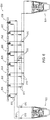
- FIG. 4 is an illustration of spatial separation of multiple propulsors driven by a s-CO 2 combustion cycle, according to one exemplary embodiment.
- System 400 includes a power-producing device 402 having a closed-loop system 404.
- closed-loop system 404 provides power to a turbine that is physically positioned within power-producing device 402, which is used to power a fan or turboprop that is also positioned within power-producing device 402.
- each propulsor 406 includes a gear drive 412 that changes rotational speed of each respective shaft between turbines 410 and their respective fan blades.
- gear drives 412 may be eliminated if, for example, there is no desire or need to alter rotational speed as provided by the respective turbine 410.
- each propulsor 406 is powered in parallel by extracting the working fluid in parallel via supply lines 414. After passing through each respective turbine 410, the working fluid passes to a return manifold 416 via return lines 418. Accordingly, because power extraction is in parallel, temperature and pressure of the working fluid is essentially the same as it is provided to each supply line 414, and pressure drop is essentially the same in each turbine 410. In such fashion, each propulsor 406 is provided with working fluid at essentially the same condition, such that power provided to each propulsor 406 is essentially uniform. It is contemplated, however, that an alternate embodiment may include some or all propulsors having a serial arrangement, in which case a pressure drop may occur between supply lines (such as lines 414).
- each propulsor 406 is driven by expansion of the cycle's working fluid, and speed control of each respective propulsor may be controlled by individual drive gears 412. Accordingly, conversion inefficiencies are reduced and overall mass of conversion equipment is reduced as well, in that one power-producing device 402 provides power to multiple propulsors 406.
- FIG. 5 illustrates a distributed propulsor system 500, as described in FIG. 4 , having a power-producing device 502 having a closed-loop system 504.
- system 500 includes distribution redundancy and reconfigurability that can be achieved via parallel distribution paths and isolation valves to isolate portions of the system to support a fail-safe operation.
- System 500 includes multiple propulsors 506 that are supplied by a first supply manifold 508 and a second supply manifold 510.
- Each supply line 508, 510 includes respective supply lines 512, 514 that are separably controllable via respective supply isolation valves 516, 518.
- Redundant return manifolds 520, 522 are also included, having return lines to each from propulsors 506 which may separably isolated via respective isolation valves in the return lines, as illustrated.
- system 500 not only provides redundant supply manifolds, but includes redundant supply lines having their own individual control capability. In operation, it may be desirable to operate both supply and/or return manifolds simultaneously, or it may be desirable to operate only one of them during operation. Regardless, in the event of a fault in one of the propulsors, one of the supply manifolds, one of the supply lines, or one of the return manifolds or lines, then such fault may be isolated from the system without negative impact to other portions of the system. For instance, if one of propulsors 506 develops a fault, it may be isolated via proper operation of the isolation valves, and the other propulsors 506 may continue operation. In another example, if one of the supply or return lines or manifolds develops a fault, then the fault may be isolated from operation and all propulsors 506 may continue in safe operation until the aircraft is safely returned for repair.
- system 500 includes a control system or computer 524 that may be used to operate each or the isolation valves illustrated or described herein.
- control system 524 may be operated to maintain pressures throughout the system and to coordinate opening and closing of isolation valves to ensure a proper mass flow throughout. For instance, in the event of a failure in a return path, isolation valves identified with element 526 may be closed via controller 524 to isolate the faulty return path.
- FIG. 6 illustrates a distributed propulsor system 600 having yet further redundant capabilities for fault isolation and safe operation.
- System 600 includes a first power-producing device 602 and a second power-producing device 604.
- each system 602, 604 provides power to respective banks of propulsors 606, 608, and as also described above, each bank of propulsors includes their own respective and redundant supply manifolds and supply lines, as well as return manifolds and return lines.
- power-producing device 602 provides power, as describe above via a closed-loop system, to propulsors 606.
- power-producing device 604 provides power, as describe above via a closed-loop system, to propulsors 608
- redundancy is provided not only in the ability to isolate individual propulsors 606, 608, but in the event of a catastrophic failure of one of devices 602, 604, the failed device 602, 604 may be isolated from operation while the other and operational device 602, 604 may continue safe operation until the aircraft can be safely landed for repair.
- isolation valves 610 may be used to isolate individual propulsors, or may be used if selectively controlled to isolate individual manifolds or even an entire power-producing device from the rest of the system.
- isolation valves identified as elements may be used to isolate device 602 from operation, in the event of a failure of device 602.
- Each system 400, 500, 600 described above includes a respective power-producing device 402, 502, and 602/604.
- Each power-producing device 402, 502, and 602/604 is illustrated having a particular arrangement that is described with respect to FIG. 7 below. However, it is contemplated that illustrated power-producing devices 402, 502, and 602/604 other exemplary engine arrangements having a closed-loop system may be employed.
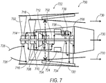
- FIG. 7 is an illustration of an exemplary gas turbine or turbofan 700 having multiple rotational shafts and a closed-loop system power-producing circuit that includes its own working fluid, such as a s-CO 2 system, which may be implemented in any one of the preceding exemplary embodiments.
- Turbofan 700 may be used, as will be further described and illustrated, to provide power via its s-CO 2 system to distributed propulsors.
- Turbofan 700 includes a first shaft 702 coupled to a first turbine 704 and a first compressor 706.
- a second shaft 708 is coupled to a second turbine 710 and a second compressor 712.
- a third shaft 714 is coupled to a third turbine 716 and a fan assembly 718.
- a heat rejection heat exchanger 720 is configured to reject heat from a closed-loop system 722 with air passed from fan assembly 718.
- closed-loop system 722 includes carbon dioxide as a working fluid and is configured to operate as a super-critical (s-CO 2 ) system.
- a combustor 724 is positioned to receive compressed air from the second compressor 712 as a core stream 726.
- the closed-loop system 722 includes the first, second, and third turbines 704, 710, 716 and the first compressor 712, and receives energy input from the combustor 724.
- a bypass airflow 728 is also generated from a fan assembly732, causing air to flow across heat rejection heat exchanger 720, and combustion products from combustor 724 (resulting from combustion that results in part from core stream 726) and bypass airflow 728 both produce a thrust 730 for turbofan 700.
- First compressor 706 of closed-loop system 722 is coupled to shaft 702 for compressing the working fluid, and turbine 704 expands the working fluid to extract the power therefrom.
- combustor 724 provides power input to the working fluid of closed-loop system 722, which in turn is expanded (and energy extracted therefrom) by turbines 704, 710, 716 before heat is rejected in heat rejection heat exchanger 720.
- the working fluid is compressed in compressor 706 before entering combustor 724.
- turbofan 700 may include a re-compression compressor 734, and a low temperature recuperative heat exchanger 736 and a high temperature recuperative heat exchanger 738.
- Operation of the components within closed-loop system 722 may be optimized by maximizing component efficiency by tailoring rotational speeds of each.
- fan assembly 718 typically operates at a speed much lower than that of compressors and turbines.
- compressor 712 operates to compress air for core stream 726 for combustion in combustor 724.
- compressor 706 is within closed-loop system 722 and is therefore configured to compress carbon dioxide as closed-loop system 722 operates in super-critical mode. Accordingly, first, the second, and the third shafts 702, 708, 714 are separately operable at different speeds from one another, and therefore operable according to their respective optimal design speeds.
- a rotational speed of fan assembly 718 may be further reduced by use a gear 732 that is coupled between shaft 714 and fan assembly 718. Accordingly, gear 732 reduces a rotation of a fan blade within the fan blade assembly relative to a rotational speed of the shaft 714.
- Turbofan 700 includes an inner housing 732 that houses at least a portion of the first, second, and third shafts 702, 708, 714, and passes air therethrough from fan assembly 718 to combustor 724, and bypass air 728 passes from fan assembly 718 and as bypass air 728 passes externally to inner housing 734 to provide cooling to heat rejection heat exchanger 720. Thrust 730 is thereby provided from both combustion byproducts from combustor 724 and from bypass air 728.
- FIG. 7 illustrates a s-CO 2 driven turbofan with independently driven compression and propulsion devices.
- compression devices There are two compression devices illustrated in this cycle: a low pressure (LP) compressor 712 and s-CO 2 compressor 704.
- Compressor 712 provides core air 726 to combustor 724 and s-CO 2 compressor 706 provides the pressure rise which drives the s-CO 2 power cycle.
- the propulsion element is a single stage fan assembly 718 which provides aircraft thrust as well as provides air flow across the heat exchange to the support power cycle.
- This engine employs a sCO2 power generation system. It includes a CO 2 compressor, a heat absorption heat exchanger integrated with the combustor, an expander, and the heat rejection exchanger built-in in the annular cross-section shaped by the nacelle and the baffle.
- the CO 2 compressor, the CO 2 expander, the fan assembly, and the air compressor are placed on the same shaft.
- the net power generated by the s-CO2 cycle is used to drive the fan and the low pressure air compressor.
- each of these devices operating on an independent shaft, the task of speed matching for each of the devices is simplified.
- the speed for each compressor/turbine or fan/turbine shaft can be selected to optimize the performance of each set of components. This will lead to a more flexibility in propulsion system design and a more efficient s-CO 2 cycle.
- Turbofan 700 is one example of a power source having closed-loop system 722 which operates having a working fluid that operates as a s-CO 2 system. It is contemplated that other engine arrangements may be employed as well to provide power for distributed propulsors. In one alternative example, for instance, one or more of shafts 702, 708, and 714 may be combined as a single shaft.
- heat rejection heat exchanger 720 is shown in FIG. 7 as being positioned at an angle with respect to bypass airflow 728 (to enhance heat transfer therethrough), it is contemplated that in another example heat rejection heat exchanger 720 may be positioned closer to inner housing 734 to make a more compact overall arrangement while taking into account the impact on the ability to reject heat using heat rejection heat exchanger 720.
- exemplary arrangements contemplated may include multiple fan assemblies, such as fan assembly 718, or a closed-loop system 722 having recuperative heat exchangers to provide overall improved thermodynamic efficiency. Accordingly, a distributed propulsor system as will be further described may employ
- a method of providing power via one or more gas turbine engines includes providing cooling to a heat rejection heat exchanger via a fan that provides a cooling stream, wherein the heat rejection heat exchanger cools a working fluid within a closed-loop system, and distributing power to one or more distributed propulsors from the closed-loop system via the working fluid, to provide thrust to an aircraft.
Landscapes
- Engineering & Computer Science (AREA)
- Mechanical Engineering (AREA)
- Chemical & Material Sciences (AREA)
- Combustion & Propulsion (AREA)
- General Engineering & Computer Science (AREA)
- Aviation & Aerospace Engineering (AREA)
- Chemical Kinetics & Catalysis (AREA)
- Engine Equipment That Uses Special Cycles (AREA)
Description
- An improved apparatus and method of operating a propulsion system includes providing power to distributed propulsors using carbon dioxide (CO2) operated in super-critical cycle.
- It has become increasingly desirable to increase the efficiency and reduce the size of power-producing or thrust-producing devices such as gas turbine engines. Gas turbine engines typically include one or more shafts that include compressors, bypass fans, and turbines. Typically, air is forced into the engine and passed into a compressor. The compressed air is passed to a combustor, and at high temperature and pressure the combustion products are passed into a turbine. The turbine provides power to the shaft, which in turn provides the power to the compressor and bypass fan or gearbox. Thrust is thereby produced from the air that passes from the bypass fan, as well as from the thrust expended in the turbine combustion products. This system is typically packaged together with power production and thrust generation co-located.
- However, air can be thermodynamically inefficient, especially during high altitude operation of the engine (such as in an aircraft application). Air that enters the engine is of low pressure, therefore low density. In order to reach the needed pressure and temperature at the combustor exit, the air is compressed to very high pressure ratios and heated up to very high temperatures in the combustors. In order to provide adequate mass flow rate, significant volume flow rate of the low density air is pumped through high pressure ratio consuming significant amount of power. As a result the engines are made of large and heavy components, consume large amount to fuel, and may include significant operational and maintenance expenses to cope with high combustion temperatures.
- To increase system efficiency and reduce component size and complexity of turbomachinery, some power-producing or thrust-producing use a closed cycle super-critical carbon dioxide (s-CO2) system. This system provides significantly improved efficiencies compared to Brayton and other air-based systems by operating in a super-critical region (operating at a temperature and pressure that exceed the critical point). That is, a phase-diagram of CO2, as is commonly known, includes a "triple point" as the point that defines the temperature and pressure where solid, liquid, and vapor meet. The critical point is the top of the dome made up of the saturated liquid and saturated vapor lines. Above the critical point is the gaseous region. At the triple point the fluid can exist in liquid, vapor, or in a mixture of the both states. However, at higher temperature and pressure, a critical point is reached which defines a temperature and pressure where gas, liquid, and a super-critical region occur.
- Fluids have a triple point, a critical point, saturated liquid and vapor lines, and a super-critical region. One in particular, carbon dioxide, is particularly attractive for such operation due to its critical temperature and pressure of approximately 31°C and 73 atmospheres, respectively, as well as due to its lack of toxicity. Thus, s-CO2 - based systems may be operated having very dense super-critical properties, such as approximately 460 kg/m3. The excellent combination of the thermodynamic properties of carbon dioxide may result in improved overall thermodynamic efficiency and therefore a tremendously reduced system size. Due to the compact nature and high power density of a power source that is powered with a super-critical cycle, the overall size of engine may be significantly reduced, as well.
- Aircraft typically include one or two propulsion systems placed on each wing or integrated the aft fuselage or tail. Their placement is based at least in part on the size of the thrust-producing devices, such as gas turbine engines, in which air is traditionally used as the working fluid. However, typical propulsion systems are sized to account for a mis-match between the LP shaft speed of the engine and the desired speed of the propulsor. Not only does this result in conversion inefficiencies, but additional mass as well. Distributed propulsion is a method which addresses this sizing mismatch by decoupling the propulsor from the power shaft and integrating it more closely with the air vehicle for aerodynamic improvement. This also allows for higher bypass ratios, and air vehicle lift or drag augmentation.
- As such, there is a need to improve overall propulsion efficiencies and reduce mass employing a s-CO2 operation.
- According to the present disclosure, there is provided a power and propulsion system and a method of providing power via one or more gas turbine engines, as set forth in the appended claims.
- While the claims are not limited to a specific illustration, an appreciation of the various aspects is best gained through a discussion of various examples thereof. Referring now to the drawings, exemplary illustrations are shown in detail. Although the drawings represent the illustrations, the drawings are not necessarily to scale and certain features may be exaggerated to better illustrate and explain an innovative aspect of an example. Further, the exemplary illustrations described herein are not intended to be exhaustive or otherwise limiting or restricted to the precise form and configuration shown in the drawings and disclosed in the following detailed description. Exemplary illustrations are described in detail by referring to the drawings as follows:
-
FIG. 1 is an illustration of a conventional gas turbine engine; -
FIG. 2 is an illustration of an exemplary air vehicle having a distributed propulsion; -
FIG. 3 is an illustration of an exemplary air vehicle having a distributed propulsion; -
FIG. 4 is an illustration of spatial separation of multiple propulsors driven by a s-CO2 combustion cycle; -
FIG. 5 is an illustration of spatial separation of multiple propulsors having a fault isolation and recovery capability through isolation and redundancy; -
FIG. 6 is an illustration of spatial separation of multiple propulsors having a redundant power distribution system; and -
FIG. 7 is an illustration of an exemplary gas turbine having a turbofan and multiple rotational shafts and a closed-loop system power-producing circuit. - An exemplary gas turbine engine is described herein, and various embodiments thereof. According to the disclosure, a gas turbine engine uses a power source to provide power to the shaft, while providing adequate power and thrust for aircraft and other purposes.
- Various applications include, as examples, a turbojet, a turbofan, adaptable, turboprop and turboshaft engine configurations. The turbojet derives most of its thrust from the core stream and is generally most advantageous in high altitude and/or high mach regimes. Turbojets bypass minimal airflow around the core so they tend to be smaller diameter, noisy and drag efficient. The turbofan, on the other hand, derives most of its thrust from the bypass stream which offers advantages in fuel savings mostly in subsonic applications. Turbofans bypass a high amount of airflow around the core and appear larger in diameter. Because of the larger fan turning more slowly they produce less noise than a turbojet.
- Turboprop engines characteristically attach a turbine engine to drive a propeller instead of a fan. Because propellers typically turn more slowly because of their larger diameter, a gearbox may be provided between the turbine engine and the propeller. In a turboshaft application, the turbine connects to something other than a fan or propeller, often a helicopter rotor or shaft in a marine application. Turboshafts typically include a gearbox between the turbine engine and rotor or shaft.
-
FIG. 1 illustrates an exemplary schematic diagram of agas turbine machine 10 that is a primary mover or thrust source for an aircraft. Theturbine machine 10 includes aprimary compressor 12, acombustor 14 and aprimary turbine assembly 16. Afan 18 includes anosecone assembly 20,blade members 22 and afan casing 24. Theblade members 22 direct low pressure air to abypass flow path 26 and to thecompressor intake 28, which in turn provides airflow tocompressor 12. The engine provides two major functions: propulsion and power generation used to rotate the compressors, turbines, and the bypass fan. The major function, propulsion, includes fairly low air pressures and temperatures, which are approximately equal to the pressures and temperatures exiting the gas turbine engine. However, the air pressure ratios and temperatures generated in the gas turbine engine are relatively very high. The high pressure ratios and temperatures are needed to provide the power generation function - A closed-loop system in this regard refers to a power-producing circuit that includes its own working fluid, such as a s-CO2 system, and which operates in compression, expansion, and heat rejection in a closed-loop analogous to a closed-loop refrigeration system. That is, aside from incidental leakage of the working fluid, the working fluid does not otherwise contact the external environment during operation.
- Thus, in general, a power-producing device includes an inner housing for passing a core stream of air, the inner housing houses a first shaft coupled to a first turbine and a first compressor, a second shaft coupled to a second turbine and a second compressor, a third shaft coupled to a third turbine and a fan assembly, a combustor positioned to receive compressed air from the second compressor, and a heat rejection heat exchanger configured to reject heat from a closed-loop system. The closed-loop system includes the first, second, and third turbines and the first compressor and receives energy input from the combustor.
-
FIGS. 2 and 3 illustrate exemplary air vehicles having distributed propulsion.FIG. 2 , in one example, illustrates a blended wing body aircraft which is a fixed-wing aircraft having no clear dividing line between wings and the main body of the aircraft.FIG. 3 , in another example, illustrates a more conventional aircraft having two wings extending from a traditional fuselage. Both examples benefit from a distributed propulsion system as disclosed herein, in that one or a few essentially point sources of thrust obtained in more conventional designs are replaced having numerous distributed propulsors. -
FIG. 4 is an illustration of spatial separation of multiple propulsors driven by a s-CO2 combustion cycle, according to one exemplary embodiment.System 400 includes a power-producingdevice 402 having a closed-loop system 404. Typically, as will be further illustrated with respect toFIG. 7 , closed-loop system 404 provides power to a turbine that is physically positioned within power-producingdevice 402, which is used to power a fan or turboprop that is also positioned within power-producingdevice 402. - However, as shown in
FIG. 4 , power may be extracted to one ormore propulsors 406 that are distributed and remote from power-producingdevice 402. That is, working fluid (carbon dioxide in this example) passes from closed-loop system 404 via asupply manifold 408 and provides power via expansion of the working fluid to each ofpropulsors 406 viarespective turbines 410. In the example illustrated, eachpropulsor 406 includes agear drive 412 that changes rotational speed of each respective shaft betweenturbines 410 and their respective fan blades. However, in an alternate arrangement, one or more gear drives 412 may be eliminated if, for example, there is no desire or need to alter rotational speed as provided by therespective turbine 410. - As shown, each
propulsor 406 is powered in parallel by extracting the working fluid in parallel viasupply lines 414. After passing through eachrespective turbine 410, the working fluid passes to areturn manifold 416 via return lines 418. Accordingly, because power extraction is in parallel, temperature and pressure of the working fluid is essentially the same as it is provided to eachsupply line 414, and pressure drop is essentially the same in eachturbine 410. In such fashion, eachpropulsor 406 is provided with working fluid at essentially the same condition, such that power provided to eachpropulsor 406 is essentially uniform. It is contemplated, however, that an alternate embodiment may include some or all propulsors having a serial arrangement, in which case a pressure drop may occur between supply lines (such as lines 414). - As such, no conversion equipment is necessary to provide the fluidic power distribution. Instead, each
propulsor 406 is driven by expansion of the cycle's working fluid, and speed control of each respective propulsor may be controlled by individual drive gears 412. Accordingly, conversion inefficiencies are reduced and overall mass of conversion equipment is reduced as well, in that one power-producingdevice 402 provides power tomultiple propulsors 406. -
FIG. 5 illustrates a distributedpropulsor system 500, as described inFIG. 4 , having a power-producingdevice 502 having a closed-loop system 504. However,system 500 includes distribution redundancy and reconfigurability that can be achieved via parallel distribution paths and isolation valves to isolate portions of the system to support a fail-safe operation. -
System 500 includesmultiple propulsors 506 that are supplied by afirst supply manifold 508 and asecond supply manifold 510. Eachsupply line respective supply lines supply isolation valves 516, 518.Redundant return manifolds propulsors 506 which may separably isolated via respective isolation valves in the return lines, as illustrated. - Accordingly,
system 500 not only provides redundant supply manifolds, but includes redundant supply lines having their own individual control capability. In operation, it may be desirable to operate both supply and/or return manifolds simultaneously, or it may be desirable to operate only one of them during operation. Regardless, in the event of a fault in one of the propulsors, one of the supply manifolds, one of the supply lines, or one of the return manifolds or lines, then such fault may be isolated from the system without negative impact to other portions of the system. For instance, if one ofpropulsors 506 develops a fault, it may be isolated via proper operation of the isolation valves, and theother propulsors 506 may continue operation. In another example, if one of the supply or return lines or manifolds develops a fault, then the fault may be isolated from operation and allpropulsors 506 may continue in safe operation until the aircraft is safely returned for repair. - It is contemplated that system 500 (and subsequently described systems disclosed herein), includes a control system or
computer 524 that may be used to operate each or the isolation valves illustrated or described herein. As such,control system 524 may be operated to maintain pressures throughout the system and to coordinate opening and closing of isolation valves to ensure a proper mass flow throughout. For instance, in the event of a failure in a return path, isolation valves identified withelement 526 may be closed viacontroller 524 to isolate the faulty return path. -
FIG. 6 illustrates a distributedpropulsor system 600 having yet further redundant capabilities for fault isolation and safe operation.System 600 includes a first power-producingdevice 602 and a second power-producingdevice 604. As shown, eachsystem propulsors device 602 provides power, as describe above via a closed-loop system, to propulsors 606. Additionally, power-producingdevice 604 provides power, as describe above via a closed-loop system, topropulsors 608 - Accordingly, redundancy is provided not only in the ability to isolate
individual propulsors devices device operational device - As such,
isolation valves 610 may be used to isolate individual propulsors, or may be used if selectively controlled to isolate individual manifolds or even an entire power-producing device from the rest of the system. In one example, isolation valves identified as elements may be used to isolatedevice 602 from operation, in the event of a failure ofdevice 602. - Each
system device device FIG. 7 below. However, it is contemplated that illustrated power-producingdevices -
FIG. 7 is an illustration of an exemplary gas turbine orturbofan 700 having multiple rotational shafts and a closed-loop system power-producing circuit that includes its own working fluid, such as a s-CO2 system, which may be implemented in any one of the preceding exemplary embodiments.Turbofan 700 may be used, as will be further described and illustrated, to provide power via its s-CO2 system to distributed propulsors.Turbofan 700 includes afirst shaft 702 coupled to afirst turbine 704 and afirst compressor 706. Asecond shaft 708 is coupled to asecond turbine 710 and asecond compressor 712. Athird shaft 714 is coupled to athird turbine 716 and afan assembly 718. A heatrejection heat exchanger 720 is configured to reject heat from a closed-loop system 722 with air passed fromfan assembly 718. In one example closed-loop system 722 includes carbon dioxide as a working fluid and is configured to operate as a super-critical (s-CO2) system. Acombustor 724 is positioned to receive compressed air from thesecond compressor 712 as acore stream 726. The closed-loop system 722 includes the first, second, andthird turbines first compressor 712, and receives energy input from thecombustor 724. Abypass airflow 728 is also generated from a fan assembly732, causing air to flow across heatrejection heat exchanger 720, and combustion products from combustor 724 (resulting from combustion that results in part from core stream 726) andbypass airflow 728 both produce athrust 730 forturbofan 700. -
First compressor 706 of closed-loop system 722 is coupled toshaft 702 for compressing the working fluid, andturbine 704 expands the working fluid to extract the power therefrom. In operation,combustor 724 provides power input to the working fluid of closed-loop system 722, which in turn is expanded (and energy extracted therefrom) byturbines rejection heat exchanger 720. The working fluid is compressed incompressor 706 before enteringcombustor 724. In the example illustrated, to improveefficiency turbofan 700 may include are-compression compressor 734, and a low temperaturerecuperative heat exchanger 736 and a high temperaturerecuperative heat exchanger 738. - Operation of the components within closed-
loop system 722 may be optimized by maximizing component efficiency by tailoring rotational speeds of each. For instance,fan assembly 718 typically operates at a speed much lower than that of compressors and turbines. In addition, however,compressor 712 operates to compress air forcore stream 726 for combustion incombustor 724. Whereascompressor 706 is within closed-loop system 722 and is therefore configured to compress carbon dioxide as closed-loop system 722 operates in super-critical mode. Accordingly, first, the second, and thethird shafts shaft 714 coupled tofan assembly 718 is separately operable, a rotational speed offan assembly 718 may be further reduced by use agear 732 that is coupled betweenshaft 714 andfan assembly 718. Accordingly,gear 732 reduces a rotation of a fan blade within the fan blade assembly relative to a rotational speed of theshaft 714. -
Turbofan 700 includes aninner housing 732 that houses at least a portion of the first, second, andthird shafts fan assembly 718 tocombustor 724, andbypass air 728 passes fromfan assembly 718 and asbypass air 728 passes externally toinner housing 734 to provide cooling to heatrejection heat exchanger 720.Thrust 730 is thereby provided from both combustion byproducts fromcombustor 724 and frombypass air 728. - Thus,
FIG. 7 illustrates a s-CO2 driven turbofan with independently driven compression and propulsion devices. There are two compression devices illustrated in this cycle: a low pressure (LP)compressor 712 and s-CO2 compressor 704.Compressor 712 providescore air 726 tocombustor 724 and s-CO2 compressor 706 provides the pressure rise which drives the s-CO2 power cycle. The propulsion element is a singlestage fan assembly 718 which provides aircraft thrust as well as provides air flow across the heat exchange to the support power cycle. - This engine employs a sCO2 power generation system. It includes a CO2 compressor, a heat absorption heat exchanger integrated with the combustor, an expander, and the heat rejection exchanger built-in in the annular cross-section shaped by the nacelle and the baffle. The CO2 compressor, the CO2 expander, the fan assembly, and the air compressor are placed on the same shaft. The net power generated by the s-CO2 cycle is used to drive the fan and the low pressure air compressor.
- With each of these devices operating on an independent shaft, the task of speed matching for each of the devices is simplified. The speed for each compressor/turbine or fan/turbine shaft can be selected to optimize the performance of each set of components. This will lead to a more flexibility in propulsion system design and a more efficient s-CO2 cycle.
-
Turbofan 700 is one example of a power source having closed-loop system 722 which operates having a working fluid that operates as a s-CO2 system. It is contemplated that other engine arrangements may be employed as well to provide power for distributed propulsors. In one alternative example, for instance, one or more ofshafts - And, although heat
rejection heat exchanger 720 is shown inFIG. 7 as being positioned at an angle with respect to bypass airflow 728 (to enhance heat transfer therethrough), it is contemplated that in another example heatrejection heat exchanger 720 may be positioned closer toinner housing 734 to make a more compact overall arrangement while taking into account the impact on the ability to reject heat using heatrejection heat exchanger 720. - Other exemplary arrangements contemplated may include multiple fan assemblies, such as
fan assembly 718, or a closed-loop system 722 having recuperative heat exchangers to provide overall improved thermodynamic efficiency. Accordingly, a distributed propulsor system as will be further described may employ - Thus, in operation, a method of providing power via one or more gas turbine engines includes providing cooling to a heat rejection heat exchanger via a fan that provides a cooling stream, wherein the heat rejection heat exchanger cools a working fluid within a closed-loop system, and distributing power to one or more distributed propulsors from the closed-loop system via the working fluid, to provide thrust to an aircraft.
- Aspects of the disclosure will be described below by numbered clauses:
- 1. A power and
propulsion system - an
air compressor - a
combustor core stream 726; and - a closed-
loop system combustor 724 and rejects heat to a cooling stream, the closed-loop system - a
fan - one or more distributed
propulsors thrust 730.
- a
- an
- 2. The power and
propulsion system - the closed-
loop system - a
carbon dioxide compressor 706; - a closed-
loop turbine 704; - a heat
rejection heat exchanger 720; - one or more
additional turbines propulsors
- a
- the closed-
loop system - receive thermal energy from the heat
rejection heat exchanger 720; - reject heat to the cooling stream; and
- provide a related portion of a carbon dioxide stream exiting the
combustor loop turbine 704 driving thecarbon dioxide compressor 706 and for eachadditional turbine propulsors
- receive thermal energy from the heat
- the closed-
- 3. The power and
propulsion system - a
first shaft 714 having afirst turbine 716 that receives power in theclosed loop system fan 718; - a
second shaft 714 having asecond turbine 710 that receives power in theclosed loop system second shaft 714 including theair compressor 712; - a
third shaft 702 having athird turbine 704 that receives power in theclosed loop system combustor 724 via the working fluid, thethird shaft 702 including acompressor 706 that receives the working fluid from a heatrejection heat exchanger 720 that rejects the heat to the cooling stream.
- a
- 4. The power and
propulsion system propulsors device air compressor combustor more turbines 704 andcompressors 706 of the closed-loop system - 5. The power and
propulsion system loop system first supply manifold first return manifold propulsors respective supply line line 418 in fluid communication with the respectivefirst supply manifold first return manifold - 6. The power and
propulsion system propulsors supply manifolds - 7. The power and
propulsion system - a
second supply manifold 510 and asecond return manifold 522 that provides redundant supply and return of working fluid to thepropulsors - an
isolation valve propulsors ofthe supply manifolds manifolds supply lines lines 418.
- a
- 8. The power and
propulsion system device loop system propulsors propulsors - 9. A method of providing power via one or more
gas turbine engines - providing cooling to a heat
rejection heat exchanger 720 via afan rejection heat exchanger 720 cools a working fluid within a closed-loop system - distributing power to one or more distributed
propulsors loop system thrust 730.
- providing cooling to a heat
- 10. The method of clause 9, wherein the closed-
loop system - 11. The method of
clause 9 or 10, wherein distributing the power includes distributing via distributedpropulsors device air compressor combustor more turbines 704 andcompressors 706 of the closed-loop system - 12. The method of any of clauses 9 to 11, wherein the closed-
loop system first supply manifold first return manifold propulsors respective supply line line 418 in fluid communication with the respectivefirst supply manifold first return manifold - 13. The method of any of clauses 9 to 12, wherein the
propulsors supply manifolds - 14. The method of any of clauses 9 to 12, providing a redundant supply and return 522 of working fluid to the propulsors via a
second supply manifold 510 and asecond return manifold 522. - 15. The method of any of clauses 9 to 14, further comprising isolating one of the
propulsors ofthe supply manifolds manifolds supply lines lines 418 via anisolation valve - 16. The method of any of clauses 9 to 15, further comprising providing power to a set of distributed
propulsors propulsors device loop system - 17. A power-producing
device - a closed-
loop system loop - a
fan rejection heat exchanger 720 to cool the working fluid within the closed-loop system - one or more distributed
propulsors thrust 730 to an aircraft.
- a
- a closed-
- 18. The power-producing
device propulsors device air compressor combustor more turbines 704 andcompressors 706 of the closed-loop system - 19. The power-producing
device clause 17 or 18, wherein the closed-loop system first supply manifold first return manifold propulsors respective supply line line 418 in fluid communication with the respectivefirst supply manifold first return manifold - 20. The power-producing
device propulsors supply manifolds - All terms used in the claims are intended to be given their broadest reasonable constructions and their ordinary meanings as understood by those knowledgeable in the technologies described herein unless an explicit indication to the contrary in made herein. In particular, use of the singular articles such as "a," "the," "said," etc. should be read to recite one or more of the indicated elements unless a claim recites an explicit limitation to the contrary.
Claims (15)
- A power and propulsion system (400, 500, 600, 700), comprising:an air compressor (12, 712, 718);a combustor (14, 724) positioned to receive compressed air from the air compressor as a core stream (726); anda closed-loop system (404, 504, 722) having carbon dioxide as a working fluid that receives heat from the combustor (724) and rejects heat to a cooling stream, the closed-loop system (404, 504, 722) configured to provide power to:a fan (718, 732) that provides the cooling stream; andone or more distributed propulsors (406, 506, 606, 608) that provide thrust (730).
- The power and propulsion system (400, 500, 600, 700) of claim 1, further comprising:the closed-loop system (404, 504, 722) further comprising:a carbon dioxide compressor (706);a closed-loop turbine (704);a heat rejection heat exchanger (720); andone or more additional turbines (410, 710, 716) for each of the one or more distributed propulsors (406, 506, 606, 608); andthe closed-loop system (404, 504, 722) configured to:receive thermal energy from the heat rejection heat exchanger (720);reject heat to the cooling stream; andprovide a related portion of a carbon dioxide stream exiting the combustor (14, 724) for the closed-loop turbine (704) driving the carbon dioxide compressor (706) and for each additional turbine (410, 71, 716) associated with the distributed propulsors (406, 506, 606, 608).
- The power and propulsion system (400, 500, 600, 700) of any one of the proceeding claims, further comprising:a first shaft (714) having a first turbine (716) that receives power in the closed loop system (404, 504, 722), the first shaft including the fan (718);a second shaft (714) having a second turbine (710) that receives power in the closed loop system (404, 504, 722), the second shaft (714) including the air compressor (712);a third shaft (702) having a third turbine (704) that receives power in the closed loop system (404, 504, 722) from the combustor (724) via the working fluid, the third shaft (702) including a compressor (706) that receives the working fluid from a heat rejection heat exchanger (720) that rejects the heat to the cooling stream.
- The power and propulsion system (400, 500, 600, 700) of any one of the proceeding claims, wherein the distributed propulsors (406, 506, 606, 608) are positioned removed from a power-producing device (402, 502, 602, 604) that includes the air compressor (12, 712, 718), the combustor (14, 724), and one or more turbines (704) and compressors (706) of the closed-loop system (404, 504, 722).
- The power and propulsion system (400, 500, 600, 700) of any one of the preceding claims, wherein the closed-loop system (404, 504, 722) includes a first supply manifold (408, 508, 510) and a first return manifold (416, 520, 522), and each of the propulsors (406, 506, 606, 608) includes a respective supply line (414, 512, 514) and return line (418) in fluid communication with the respective first supply manifold (408, 508, 510) and first return manifold (416, 520, 522).
- The power and propulsion system (400, 500, 600, 700) of any one of the preceding claims, wherein the propulsors (406, 506, 606, 608) are arranged in parallel with one another via the supply (408, 508, 510) and return manifolds (416, 520, 522).
- The power and propulsion system (400, 500, 600, 700) of any one of the preceding claims, further comprising:a second supply manifold (510) and a second return manifold (522) that provides redundant supply and return of working fluid to the propulsors (406, 506, 606, 608); andan isolation valve (516, 518, 610) that is configured to isolate one of the propulsors (406, 506, 606, 608) from one of the supply manifolds (408, 508, 510), return manifolds (416, 520, 522), supply lines (414, 512, 514), and return lines (418).
- The power and propulsion system (400, 500, 600, 700) of any one of the preceding claims, further comprising a second power-producing device (602, 604) having its own closed-loop system (404, 504, 722) to provide power to a set of distributed propulsors (406, 506, 606, 608) different from the one or more distributed propulsors (406, 506, 606, 608).
- A method of providing power via one or more gas turbine engines (10, 700), comprising:providing cooling to a heat rejection heat exchanger (720) via a fan (718, 732) that provides a cooling stream, wherein the heat rejection heat exchanger (720) cools a working fluid within a closed-loop system (404, 504, 722); anddistributing power to one or more distributed propulsors (406, 506, 606, 608) from the closed-loop system (404, 504, 722) via the working fluid, to provide thrust (730).
- The method of claim 9, wherein the closed-loop system (404, 504, 722) includes carbon dioxide as a working fluid.
- The method of any one of claim 9 or 10, wherein distributing the power includes distributing via distributed propulsors (406, 506, 606, 608) that are positioned removed from a power-producing device (402, 502, 602, 604) that includes an air compressor (12, 712, 718), a combustor (14, 724), and one or more turbines (704) and compressors (706) of the closed-loop system (404, 504, 722).
- The method of any one of claims 9 to 11, wherein the closed-loop system (404, 504, 722) includes a first supply manifold (408, 508, 510) and a first return manifold (416, 520, 522), and each ofthe propulsors (406, 506, 606, 608) includes a respective supply line (414, 512, 514) and return line (418) in fluid communication with the respective first supply manifold (408, 508, 510) and first return manifold (416, 520, 522).
- The method of any one of claims 9 to 12, providing a redundant supply and return (522) of working fluid to the propulsors via a second supply manifold (510) and a second return manifold (522).
- The method of any one of claims 9 to 13, further comprising isolating one of the propulsors (406, 506, 606, 608) from one of the supply manifolds (408, 508, 510), return manifolds (416, 520, 522), supply lines (414, 512, 514), and return lines (418) via an isolation valve (516, 518, 610).
- The method of any one of claims 9 to 14, further comprising providing power to a set of distributed propulsors (406, 506, 606, 608) different from the one or more distributed propulsors (406, 506, 606, 608) via a second power-producing device (602, 604) having its own closed-loop system (404, 504, 722).
Applications Claiming Priority (1)
| Application Number | Priority Date | Filing Date | Title |
|---|---|---|---|
| US201562222282P | 2015-09-23 | 2015-09-23 |
Publications (2)
| Publication Number | Publication Date |
|---|---|
| EP3147219A1 true EP3147219A1 (en) | 2017-03-29 |
| EP3147219B1 EP3147219B1 (en) | 2021-03-17 |
Family
ID=57103804
Family Applications (1)
| Application Number | Title | Priority Date | Filing Date |
|---|---|---|---|
| EP16190031.1A Active EP3147219B1 (en) | 2015-09-23 | 2016-09-22 | Propulsion system using supercritical co2 power transfer |
Country Status (2)
| Country | Link |
|---|---|
| US (1) | US10458364B2 (en) |
| EP (1) | EP3147219B1 (en) |
Cited By (1)
| Publication number | Priority date | Publication date | Assignee | Title |
|---|---|---|---|---|
| US10584635B2 (en) | 2015-10-08 | 2020-03-10 | Rolls-Royce North American Technologies, Inc. | All CO2 aircraft |
Families Citing this family (6)
| Publication number | Priority date | Publication date | Assignee | Title |
|---|---|---|---|---|
| EP3109433B1 (en) * | 2015-06-19 | 2018-08-15 | Rolls-Royce Corporation | Engine driven by sc02 cycle with independent shafts for combustion cycle elements and propulsion elements |
| US11230948B2 (en) | 2019-01-16 | 2022-01-25 | Raytheon Technologies Corporation | Work recovery system for a gas turbine engine utilizing an overexpanded, recuperated supercritical CO2 bottoming cycle |
| CN110685817A (en) * | 2019-10-11 | 2020-01-14 | 上海朝临动力科技有限公司 | Turbofan engine and aircraft |
| US11485504B2 (en) | 2020-10-27 | 2022-11-01 | Pratt & Whitney Canada Corp. | Aircraft power plant with supercritical CO2 heat engine |
| EP4253743B1 (en) | 2022-03-29 | 2025-07-16 | RTX Corporation | Adjustable primary and supplemental power units |
| US11635023B1 (en) | 2022-04-07 | 2023-04-25 | Hamilton Sundstrand Corporation | Multi-spool CO2 aircraft power system for operating multiple generators |
Citations (5)
| Publication number | Priority date | Publication date | Assignee | Title |
|---|---|---|---|---|
| US2820599A (en) * | 1955-02-03 | 1958-01-21 | Tech Studien Ag | Dual unit jet propulsion plant for aircraft |
| US3646760A (en) * | 1970-06-01 | 1972-03-07 | Rohr Corp | Vapor cycle propulsion system |
| EP1331386A2 (en) * | 2002-01-16 | 2003-07-30 | National Aerospace Laboratory of Japan | Multi-turbofan system with separate core engine |
| US20130180259A1 (en) * | 2012-01-17 | 2013-07-18 | David S. Stapp | System and method for generating power using a supercritical fluid |
| EP3109433A1 (en) * | 2015-06-19 | 2016-12-28 | Rolls-Royce Corporation | Engine driven by sc02 cycle with independent shafts for combustion cycle elements and propulsion elements |
Family Cites Families (14)
| Publication number | Priority date | Publication date | Assignee | Title |
|---|---|---|---|---|
| US6265453B1 (en) * | 1999-07-01 | 2001-07-24 | Syntroleum Corporation | Hydrocarbon conversion system with enhanced combustor and method |
| NL1020350C2 (en) * | 2002-04-10 | 2003-10-13 | Henk Ouwerkerk | Steam and gas turbine installation. |
| US7637457B2 (en) | 2004-04-30 | 2009-12-29 | Lawrence Livermore National Security, Llc | Rankine-Brayton engine powered solar thermal aircraft |
| US8869531B2 (en) | 2009-09-17 | 2014-10-28 | Echogen Power Systems, Llc | Heat engines with cascade cycles |
| US9115605B2 (en) | 2009-09-17 | 2015-08-25 | Echogen Power Systems, Llc | Thermal energy conversion device |
| US8490397B2 (en) | 2009-11-16 | 2013-07-23 | General Electric Company | Compound closed-loop heat cycle system for recovering waste heat and method thereof |
| US8464534B1 (en) | 2010-01-21 | 2013-06-18 | Gary D. Riemer | Nitrogen pressure-based engine device |
| EP2476476B1 (en) | 2011-01-14 | 2018-05-30 | General Electric Technology GmbH | Compression of a carbon dioxide containing fluid |
| DE102011119977A1 (en) | 2011-12-02 | 2013-06-06 | Alena von Lavante | Device and method for using the waste heat of an internal combustion engine, in particular for using the waste heat of a vehicle engine |
| US8887503B2 (en) | 2011-12-13 | 2014-11-18 | Aerojet Rocketdyne of DE, Inc | Recuperative supercritical carbon dioxide cycle |
| US20140119881A1 (en) | 2012-10-31 | 2014-05-01 | General Electric Company | Apparatus for recirculating a fluid within a turbomachine and method for operating the same |
| WO2016000016A1 (en) * | 2014-06-30 | 2016-01-07 | Kerbs Autotech Pty Ltd | An internal combustion engine heat energy recovery system |
| US10101092B2 (en) * | 2014-08-22 | 2018-10-16 | Peregrine Turbine Technologies, Llc | Power generation system including multiple cores |
| US10774691B2 (en) * | 2014-12-25 | 2020-09-15 | Mitsubishi Heavy Industries Compressor Corporation | Combined cycle power plants with a steam connection line |
-
2016
- 2016-09-22 EP EP16190031.1A patent/EP3147219B1/en active Active
- 2016-09-22 US US15/273,183 patent/US10458364B2/en active Active
Patent Citations (5)
| Publication number | Priority date | Publication date | Assignee | Title |
|---|---|---|---|---|
| US2820599A (en) * | 1955-02-03 | 1958-01-21 | Tech Studien Ag | Dual unit jet propulsion plant for aircraft |
| US3646760A (en) * | 1970-06-01 | 1972-03-07 | Rohr Corp | Vapor cycle propulsion system |
| EP1331386A2 (en) * | 2002-01-16 | 2003-07-30 | National Aerospace Laboratory of Japan | Multi-turbofan system with separate core engine |
| US20130180259A1 (en) * | 2012-01-17 | 2013-07-18 | David S. Stapp | System and method for generating power using a supercritical fluid |
| EP3109433A1 (en) * | 2015-06-19 | 2016-12-28 | Rolls-Royce Corporation | Engine driven by sc02 cycle with independent shafts for combustion cycle elements and propulsion elements |
Cited By (2)
| Publication number | Priority date | Publication date | Assignee | Title |
|---|---|---|---|---|
| US10584635B2 (en) | 2015-10-08 | 2020-03-10 | Rolls-Royce North American Technologies, Inc. | All CO2 aircraft |
| EP3153690B1 (en) * | 2015-10-08 | 2025-06-04 | Rolls-Royce Corporation | All co2 aircraft |
Also Published As
| Publication number | Publication date |
|---|---|
| US20170082066A1 (en) | 2017-03-23 |
| US10458364B2 (en) | 2019-10-29 |
| EP3147219B1 (en) | 2021-03-17 |
Similar Documents
| Publication | Publication Date | Title |
|---|---|---|
| US10584635B2 (en) | All CO2 aircraft | |
| US10458364B2 (en) | Propulsion system using supercritical CO2 power transfer | |
| US11261792B2 (en) | Thermal management system with thermal bus for a gas turbine engine or aircraft | |
| US10677195B2 (en) | Engine driven by Sc02 cycle with independent shafts for combustion cycle elements and propulsion elements | |
| CA2961056C (en) | Engine bleed system with turbo-compressor | |
| EP3219964B1 (en) | Engine bleed system with multi-tap bleed array | |
| US11286853B2 (en) | Cooling system | |
| EP3219620B1 (en) | Engine bleed system with motorized compressor | |
| EP3106645B1 (en) | Gas turbine engine driven by sco2 cycle with advanced heat rejection | |
| US10457401B2 (en) | Dual-use air turbine system for a gas turbine engine | |
| EP4137686A1 (en) | Propulsion systems for aircraft | |
| US12319417B2 (en) | Reverse flow gas turbine engine having electric machine | |
| US12304641B2 (en) | Ram-air duct system |
Legal Events
| Date | Code | Title | Description |
|---|---|---|---|
| PUAI | Public reference made under article 153(3) epc to a published international application that has entered the european phase |
Free format text: ORIGINAL CODE: 0009012 |
|
| STAA | Information on the status of an ep patent application or granted ep patent |
Free format text: STATUS: THE APPLICATION HAS BEEN PUBLISHED |
|
| AK | Designated contracting states |
Kind code of ref document: A1 Designated state(s): AL AT BE BG CH CY CZ DE DK EE ES FI FR GB GR HR HU IE IS IT LI LT LU LV MC MK MT NL NO PL PT RO RS SE SI SK SM TR |
|
| AX | Request for extension of the european patent |
Extension state: BA ME |
|
| STAA | Information on the status of an ep patent application or granted ep patent |
Free format text: STATUS: REQUEST FOR EXAMINATION WAS MADE |
|
| 17P | Request for examination filed |
Effective date: 20170926 |
|
| RBV | Designated contracting states (corrected) |
Designated state(s): AL AT BE BG CH CY CZ DE DK EE ES FI FR GB GR HR HU IE IS IT LI LT LU LV MC MK MT NL NO PL PT RO RS SE SI SK SM TR |
|
| STAA | Information on the status of an ep patent application or granted ep patent |
Free format text: STATUS: EXAMINATION IS IN PROGRESS |
|
| 17Q | First examination report despatched |
Effective date: 20190902 |
|
| GRAP | Despatch of communication of intention to grant a patent |
Free format text: ORIGINAL CODE: EPIDOSNIGR1 |
|
| STAA | Information on the status of an ep patent application or granted ep patent |
Free format text: STATUS: GRANT OF PATENT IS INTENDED |
|
| INTG | Intention to grant announced |
Effective date: 20201028 |
|
| GRAS | Grant fee paid |
Free format text: ORIGINAL CODE: EPIDOSNIGR3 |
|
| GRAA | (expected) grant |
Free format text: ORIGINAL CODE: 0009210 |
|
| STAA | Information on the status of an ep patent application or granted ep patent |
Free format text: STATUS: THE PATENT HAS BEEN GRANTED |
|
| AK | Designated contracting states |
Kind code of ref document: B1 Designated state(s): AL AT BE BG CH CY CZ DE DK EE ES FI FR GB GR HR HU IE IS IT LI LT LU LV MC MK MT NL NO PL PT RO RS SE SI SK SM TR |
|
| REG | Reference to a national code |
Ref country code: GB Ref legal event code: FG4D |
|
| REG | Reference to a national code |
Ref country code: CH Ref legal event code: EP |
|
| REG | Reference to a national code |
Ref country code: DE Ref legal event code: R096 Ref document number: 602016054341 Country of ref document: DE |
|
| REG | Reference to a national code |
Ref country code: IE Ref legal event code: FG4D |
|
| REG | Reference to a national code |
Ref country code: AT Ref legal event code: REF Ref document number: 1372021 Country of ref document: AT Kind code of ref document: T Effective date: 20210415 |
|
| REG | Reference to a national code |
Ref country code: LT Ref legal event code: MG9D |
|
| PG25 | Lapsed in a contracting state [announced via postgrant information from national office to epo] |
Ref country code: NO Free format text: LAPSE BECAUSE OF FAILURE TO SUBMIT A TRANSLATION OF THE DESCRIPTION OR TO PAY THE FEE WITHIN THE PRESCRIBED TIME-LIMIT Effective date: 20210617 Ref country code: BG Free format text: LAPSE BECAUSE OF FAILURE TO SUBMIT A TRANSLATION OF THE DESCRIPTION OR TO PAY THE FEE WITHIN THE PRESCRIBED TIME-LIMIT Effective date: 20210617 Ref country code: GR Free format text: LAPSE BECAUSE OF FAILURE TO SUBMIT A TRANSLATION OF THE DESCRIPTION OR TO PAY THE FEE WITHIN THE PRESCRIBED TIME-LIMIT Effective date: 20210618 Ref country code: FI Free format text: LAPSE BECAUSE OF FAILURE TO SUBMIT A TRANSLATION OF THE DESCRIPTION OR TO PAY THE FEE WITHIN THE PRESCRIBED TIME-LIMIT Effective date: 20210317 Ref country code: HR Free format text: LAPSE BECAUSE OF FAILURE TO SUBMIT A TRANSLATION OF THE DESCRIPTION OR TO PAY THE FEE WITHIN THE PRESCRIBED TIME-LIMIT Effective date: 20210317 |
|
| REG | Reference to a national code |
Ref country code: AT Ref legal event code: MK05 Ref document number: 1372021 Country of ref document: AT Kind code of ref document: T Effective date: 20210317 |
|
| REG | Reference to a national code |
Ref country code: NL Ref legal event code: MP Effective date: 20210317 |
|
| PG25 | Lapsed in a contracting state [announced via postgrant information from national office to epo] |
Ref country code: LV Free format text: LAPSE BECAUSE OF FAILURE TO SUBMIT A TRANSLATION OF THE DESCRIPTION OR TO PAY THE FEE WITHIN THE PRESCRIBED TIME-LIMIT Effective date: 20210317 Ref country code: RS Free format text: LAPSE BECAUSE OF FAILURE TO SUBMIT A TRANSLATION OF THE DESCRIPTION OR TO PAY THE FEE WITHIN THE PRESCRIBED TIME-LIMIT Effective date: 20210317 Ref country code: SE Free format text: LAPSE BECAUSE OF FAILURE TO SUBMIT A TRANSLATION OF THE DESCRIPTION OR TO PAY THE FEE WITHIN THE PRESCRIBED TIME-LIMIT Effective date: 20210317 |
|
| PG25 | Lapsed in a contracting state [announced via postgrant information from national office to epo] |
Ref country code: NL Free format text: LAPSE BECAUSE OF FAILURE TO SUBMIT A TRANSLATION OF THE DESCRIPTION OR TO PAY THE FEE WITHIN THE PRESCRIBED TIME-LIMIT Effective date: 20210317 |
|
| PG25 | Lapsed in a contracting state [announced via postgrant information from national office to epo] |
Ref country code: AT Free format text: LAPSE BECAUSE OF FAILURE TO SUBMIT A TRANSLATION OF THE DESCRIPTION OR TO PAY THE FEE WITHIN THE PRESCRIBED TIME-LIMIT Effective date: 20210317 Ref country code: SM Free format text: LAPSE BECAUSE OF FAILURE TO SUBMIT A TRANSLATION OF THE DESCRIPTION OR TO PAY THE FEE WITHIN THE PRESCRIBED TIME-LIMIT Effective date: 20210317 Ref country code: CZ Free format text: LAPSE BECAUSE OF FAILURE TO SUBMIT A TRANSLATION OF THE DESCRIPTION OR TO PAY THE FEE WITHIN THE PRESCRIBED TIME-LIMIT Effective date: 20210317 Ref country code: EE Free format text: LAPSE BECAUSE OF FAILURE TO SUBMIT A TRANSLATION OF THE DESCRIPTION OR TO PAY THE FEE WITHIN THE PRESCRIBED TIME-LIMIT Effective date: 20210317 Ref country code: LT Free format text: LAPSE BECAUSE OF FAILURE TO SUBMIT A TRANSLATION OF THE DESCRIPTION OR TO PAY THE FEE WITHIN THE PRESCRIBED TIME-LIMIT Effective date: 20210317 |
|
| PG25 | Lapsed in a contracting state [announced via postgrant information from national office to epo] |
Ref country code: IS Free format text: LAPSE BECAUSE OF FAILURE TO SUBMIT A TRANSLATION OF THE DESCRIPTION OR TO PAY THE FEE WITHIN THE PRESCRIBED TIME-LIMIT Effective date: 20210717 Ref country code: ES Free format text: LAPSE BECAUSE OF FAILURE TO SUBMIT A TRANSLATION OF THE DESCRIPTION OR TO PAY THE FEE WITHIN THE PRESCRIBED TIME-LIMIT Effective date: 20210317 Ref country code: PT Free format text: LAPSE BECAUSE OF FAILURE TO SUBMIT A TRANSLATION OF THE DESCRIPTION OR TO PAY THE FEE WITHIN THE PRESCRIBED TIME-LIMIT Effective date: 20210719 Ref country code: PL Free format text: LAPSE BECAUSE OF FAILURE TO SUBMIT A TRANSLATION OF THE DESCRIPTION OR TO PAY THE FEE WITHIN THE PRESCRIBED TIME-LIMIT Effective date: 20210317 Ref country code: SK Free format text: LAPSE BECAUSE OF FAILURE TO SUBMIT A TRANSLATION OF THE DESCRIPTION OR TO PAY THE FEE WITHIN THE PRESCRIBED TIME-LIMIT Effective date: 20210317 Ref country code: RO Free format text: LAPSE BECAUSE OF FAILURE TO SUBMIT A TRANSLATION OF THE DESCRIPTION OR TO PAY THE FEE WITHIN THE PRESCRIBED TIME-LIMIT Effective date: 20210317 |
|
| REG | Reference to a national code |
Ref country code: DE Ref legal event code: R097 Ref document number: 602016054341 Country of ref document: DE |
|
| PLBE | No opposition filed within time limit |
Free format text: ORIGINAL CODE: 0009261 |
|
| STAA | Information on the status of an ep patent application or granted ep patent |
Free format text: STATUS: NO OPPOSITION FILED WITHIN TIME LIMIT |
|
| PG25 | Lapsed in a contracting state [announced via postgrant information from national office to epo] |
Ref country code: DK Free format text: LAPSE BECAUSE OF FAILURE TO SUBMIT A TRANSLATION OF THE DESCRIPTION OR TO PAY THE FEE WITHIN THE PRESCRIBED TIME-LIMIT Effective date: 20210317 Ref country code: AL Free format text: LAPSE BECAUSE OF FAILURE TO SUBMIT A TRANSLATION OF THE DESCRIPTION OR TO PAY THE FEE WITHIN THE PRESCRIBED TIME-LIMIT Effective date: 20210317 |
|
| 26N | No opposition filed |
Effective date: 20211220 |
|
| PG25 | Lapsed in a contracting state [announced via postgrant information from national office to epo] |
Ref country code: SI Free format text: LAPSE BECAUSE OF FAILURE TO SUBMIT A TRANSLATION OF THE DESCRIPTION OR TO PAY THE FEE WITHIN THE PRESCRIBED TIME-LIMIT Effective date: 20210317 |
|
| PG25 | Lapsed in a contracting state [announced via postgrant information from national office to epo] |
Ref country code: IT Free format text: LAPSE BECAUSE OF FAILURE TO SUBMIT A TRANSLATION OF THE DESCRIPTION OR TO PAY THE FEE WITHIN THE PRESCRIBED TIME-LIMIT Effective date: 20210317 |
|
| REG | Reference to a national code |
Ref country code: CH Ref legal event code: PL |
|
| REG | Reference to a national code |
Ref country code: BE Ref legal event code: MM Effective date: 20210930 |
|
| GBPC | Gb: european patent ceased through non-payment of renewal fee |
Effective date: 20210922 |
|
| PG25 | Lapsed in a contracting state [announced via postgrant information from national office to epo] |
Ref country code: IS Free format text: LAPSE BECAUSE OF FAILURE TO SUBMIT A TRANSLATION OF THE DESCRIPTION OR TO PAY THE FEE WITHIN THE PRESCRIBED TIME-LIMIT Effective date: 20210717 Ref country code: MC Free format text: LAPSE BECAUSE OF FAILURE TO SUBMIT A TRANSLATION OF THE DESCRIPTION OR TO PAY THE FEE WITHIN THE PRESCRIBED TIME-LIMIT Effective date: 20210317 |
|
| PG25 | Lapsed in a contracting state [announced via postgrant information from national office to epo] |
Ref country code: LU Free format text: LAPSE BECAUSE OF NON-PAYMENT OF DUE FEES Effective date: 20210922 Ref country code: IE Free format text: LAPSE BECAUSE OF NON-PAYMENT OF DUE FEES Effective date: 20210922 Ref country code: GB Free format text: LAPSE BECAUSE OF NON-PAYMENT OF DUE FEES Effective date: 20210922 Ref country code: FR Free format text: LAPSE BECAUSE OF NON-PAYMENT OF DUE FEES Effective date: 20210930 Ref country code: BE Free format text: LAPSE BECAUSE OF NON-PAYMENT OF DUE FEES Effective date: 20210930 |
|
| PG25 | Lapsed in a contracting state [announced via postgrant information from national office to epo] |
Ref country code: LI Free format text: LAPSE BECAUSE OF NON-PAYMENT OF DUE FEES Effective date: 20210930 Ref country code: CH Free format text: LAPSE BECAUSE OF NON-PAYMENT OF DUE FEES Effective date: 20210930 |
|
| PG25 | Lapsed in a contracting state [announced via postgrant information from national office to epo] |
Ref country code: HU Free format text: LAPSE BECAUSE OF FAILURE TO SUBMIT A TRANSLATION OF THE DESCRIPTION OR TO PAY THE FEE WITHIN THE PRESCRIBED TIME-LIMIT; INVALID AB INITIO Effective date: 20160922 |
|
| PG25 | Lapsed in a contracting state [announced via postgrant information from national office to epo] |
Ref country code: CY Free format text: LAPSE BECAUSE OF FAILURE TO SUBMIT A TRANSLATION OF THE DESCRIPTION OR TO PAY THE FEE WITHIN THE PRESCRIBED TIME-LIMIT Effective date: 20210317 |
|
| P01 | Opt-out of the competence of the unified patent court (upc) registered |
Effective date: 20230528 |
|
| PG25 | Lapsed in a contracting state [announced via postgrant information from national office to epo] |
Ref country code: MK Free format text: LAPSE BECAUSE OF FAILURE TO SUBMIT A TRANSLATION OF THE DESCRIPTION OR TO PAY THE FEE WITHIN THE PRESCRIBED TIME-LIMIT Effective date: 20210317 |
|
| PG25 | Lapsed in a contracting state [announced via postgrant information from national office to epo] |
Ref country code: TR Free format text: LAPSE BECAUSE OF FAILURE TO SUBMIT A TRANSLATION OF THE DESCRIPTION OR TO PAY THE FEE WITHIN THE PRESCRIBED TIME-LIMIT Effective date: 20210317 |
|
| PG25 | Lapsed in a contracting state [announced via postgrant information from national office to epo] |
Ref country code: MT Free format text: LAPSE BECAUSE OF FAILURE TO SUBMIT A TRANSLATION OF THE DESCRIPTION OR TO PAY THE FEE WITHIN THE PRESCRIBED TIME-LIMIT Effective date: 20210317 |
|
| PGFP | Annual fee paid to national office [announced via postgrant information from national office to epo] |
Ref country code: DE Payment date: 20250926 Year of fee payment: 10 |