EP3147206A1 - Active laminar flow control system with drainage - Google Patents
Active laminar flow control system with drainage Download PDFInfo
- Publication number
- EP3147206A1 EP3147206A1 EP16190075.8A EP16190075A EP3147206A1 EP 3147206 A1 EP3147206 A1 EP 3147206A1 EP 16190075 A EP16190075 A EP 16190075A EP 3147206 A1 EP3147206 A1 EP 3147206A1
- Authority
- EP
- European Patent Office
- Prior art keywords
- nacelle
- drain mechanism
- suction source
- perforations
- outer barrel
- Prior art date
- Legal status (The legal status is an assumption and is not a legal conclusion. Google has not performed a legal analysis and makes no representation as to the accuracy of the status listed.)
- Granted
Links
- 230000007246 mechanism Effects 0.000 claims abstract description 84
- 239000007788 liquid Substances 0.000 claims description 17
- 238000003491 array Methods 0.000 claims description 13
- 230000001360 synchronised effect Effects 0.000 claims description 2
- XLYOFNOQVPJJNP-UHFFFAOYSA-N water Substances O XLYOFNOQVPJJNP-UHFFFAOYSA-N 0.000 description 10
- 238000010586 diagram Methods 0.000 description 2
- 239000012530 fluid Substances 0.000 description 2
- 239000012634 fragment Substances 0.000 description 2
- 230000001737 promoting effect Effects 0.000 description 2
- 238000009825 accumulation Methods 0.000 description 1
- 230000004913 activation Effects 0.000 description 1
- 230000015556 catabolic process Effects 0.000 description 1
- 239000002131 composite material Substances 0.000 description 1
- 230000005494 condensation Effects 0.000 description 1
- 238000009833 condensation Methods 0.000 description 1
- 230000007812 deficiency Effects 0.000 description 1
- 238000006731 degradation reaction Methods 0.000 description 1
- 239000000835 fiber Substances 0.000 description 1
- 230000008014 freezing Effects 0.000 description 1
- 238000007710 freezing Methods 0.000 description 1
- 239000011159 matrix material Substances 0.000 description 1
- 239000002184 metal Substances 0.000 description 1
- 238000000034 method Methods 0.000 description 1
- 230000004048 modification Effects 0.000 description 1
- 238000012986 modification Methods 0.000 description 1
- 238000009428 plumbing Methods 0.000 description 1
- 229920000642 polymer Polymers 0.000 description 1
- 238000011176 pooling Methods 0.000 description 1
- 230000002787 reinforcement Effects 0.000 description 1
- 230000004044 response Effects 0.000 description 1
- 230000008719 thickening Effects 0.000 description 1
Images





Classifications
-
- B—PERFORMING OPERATIONS; TRANSPORTING
- B64—AIRCRAFT; AVIATION; COSMONAUTICS
- B64C—AEROPLANES; HELICOPTERS
- B64C21/00—Influencing air flow over aircraft surfaces by affecting boundary layer flow
- B64C21/02—Influencing air flow over aircraft surfaces by affecting boundary layer flow by use of slot, ducts, porous areas or the like
- B64C21/06—Influencing air flow over aircraft surfaces by affecting boundary layer flow by use of slot, ducts, porous areas or the like for sucking
-
- B—PERFORMING OPERATIONS; TRANSPORTING
- B64—AIRCRAFT; AVIATION; COSMONAUTICS
- B64D—EQUIPMENT FOR FITTING IN OR TO AIRCRAFT; FLIGHT SUITS; PARACHUTES; ARRANGEMENT OR MOUNTING OF POWER PLANTS OR PROPULSION TRANSMISSIONS IN AIRCRAFT
- B64D29/00—Power-plant nacelles, fairings or cowlings
-
- B—PERFORMING OPERATIONS; TRANSPORTING
- B64—AIRCRAFT; AVIATION; COSMONAUTICS
- B64D—EQUIPMENT FOR FITTING IN OR TO AIRCRAFT; FLIGHT SUITS; PARACHUTES; ARRANGEMENT OR MOUNTING OF POWER PLANTS OR PROPULSION TRANSMISSIONS IN AIRCRAFT
- B64D33/00—Arrangement in aircraft of power plant parts or auxiliaries not otherwise provided for
- B64D33/02—Arrangement in aircraft of power plant parts or auxiliaries not otherwise provided for of combustion air intakes
-
- B—PERFORMING OPERATIONS; TRANSPORTING
- B64—AIRCRAFT; AVIATION; COSMONAUTICS
- B64C—AEROPLANES; HELICOPTERS
- B64C2230/00—Boundary layer controls
- B64C2230/06—Boundary layer controls by explicitly adjusting fluid flow, e.g. by using valves, variable aperture or slot areas, variable pump action or variable fluid pressure
-
- B—PERFORMING OPERATIONS; TRANSPORTING
- B64—AIRCRAFT; AVIATION; COSMONAUTICS
- B64D—EQUIPMENT FOR FITTING IN OR TO AIRCRAFT; FLIGHT SUITS; PARACHUTES; ARRANGEMENT OR MOUNTING OF POWER PLANTS OR PROPULSION TRANSMISSIONS IN AIRCRAFT
- B64D33/00—Arrangement in aircraft of power plant parts or auxiliaries not otherwise provided for
- B64D33/02—Arrangement in aircraft of power plant parts or auxiliaries not otherwise provided for of combustion air intakes
- B64D2033/0226—Arrangement in aircraft of power plant parts or auxiliaries not otherwise provided for of combustion air intakes comprising boundary layer control means
-
- Y—GENERAL TAGGING OF NEW TECHNOLOGICAL DEVELOPMENTS; GENERAL TAGGING OF CROSS-SECTIONAL TECHNOLOGIES SPANNING OVER SEVERAL SECTIONS OF THE IPC; TECHNICAL SUBJECTS COVERED BY FORMER USPC CROSS-REFERENCE ART COLLECTIONS [XRACs] AND DIGESTS
- Y02—TECHNOLOGIES OR APPLICATIONS FOR MITIGATION OR ADAPTATION AGAINST CLIMATE CHANGE
- Y02T—CLIMATE CHANGE MITIGATION TECHNOLOGIES RELATED TO TRANSPORTATION
- Y02T50/00—Aeronautics or air transport
- Y02T50/10—Drag reduction
Definitions
- This disclosure relates generally to an aircraft propulsion system and, more particularly, to a nacelle for an aircraft propulsion system and a system for promoting laminar flow over portions of the nacelle to reduce drag.
- Such an ALFC system may include a plenum duct positioned at least partly inside of the nacelle. This plenum duct is fluidly coupled with perforations in the outer surface. The plenum duct is also fluidly coupled with a suction means, which draws air into the plenum duct through the perforations in the outer surface in order to modify airflow over the outer surface. This modification generally removes low energy air from a boundary layer along an extent of the outer surface to prevent that boundary layer from thickening and eventually tripping into a turbulent flow.
- a nacelle for an aircraft propulsion system.
- This nacelle includes an outer barrel and an active laminar flow control system.
- the active laminar flow control system includes an array of perforations in the outer barrel, a suction source and a drain mechanism.
- the suction source is fluidly coupled with the array of perforations.
- the drain mechanism is fluidly coupled with and between the array of perforations and the suction source.
- another nacelle for an aircraft propulsion system.
- This nacelle includes a nacelle inlet and an active laminar flow control system.
- the nacelle inlet includes an inner barrel and an outer barrel circumscribing the inner barrel.
- the inner barrel includes a sound attenuating acoustic panel.
- the active laminar flow control system includes a plurality of arrays of perforations in the outer barrel, a suction source and a drain mechanism.
- the suction source is fluidly coupled with the arrays of perforations.
- the drain mechanism is fluidly coupled with and between at least one of the arrays of perforations and the suction source.
- another nacelle for an aircraft propulsion system.
- This nacelle includes a nacelle inlet and an active laminar flow control system.
- the nacelle inlet includes and an outer barrel circumscribing the inner barrel.
- the inner barrel includes a sound attenuating acoustic panel.
- the active laminar flow control system includes an array of perforations in the outer barrel, a suction device, a drain mechanism and a controller.
- the suction source is fluidly coupled with the array of perforations.
- the drain mechanism is fluidly coupled with and between the array of perforations and the suction source.
- the controller is configured to synchronize actuation of the drain mechanism with operation of the suction source.
- the nacelle inlet includes a noselip at the leading edge, an inner barrel coupled to the inner diameter of the noselip, and an outer barrel circumscribing the inner barrel and coupled to the outer diameter of the noselip.
- the noselip and outer barrel may be separate pieces attached together, or may be integrated together to form a one piece noselip and outer barrel (an extended noselip or inlet).
- the drain mechanism may be fluidly coupled with and between each of the arrays of perforations and the suction source.
- the drain mechanism may include or be configured as a passive drain mechanism.
- the drain mechanism may alternatively include or be configured as an active drain mechanism. This active drain mechanism may be actuated based on the operation of the suction source.
- the drain mechanism may be configured to close where the suction source is operational.
- the drain mechanism may be configured to open where the suction source is non-operational.
- the drain mechanism may include or be configured as a flapper valve.
- the flapper valve may include a flap and a biasing device configured to bias the flap in an open position.
- the drain mechanism may be electronically synchronized with the suction source such that the drain mechanism is open where the suction source is non-operational and such that the drain mechanism is closed where the suction source is operational.
- the active laminar control system may include a plenum and a conduit.
- the plenum may be configured with the outer barrel and is fluidly coupled with the array of perforations.
- the conduit may fluidly couple the plenum with the suction source.
- the drain mechanism may be configured with the plenum.
- the active laminar control system may include a plenum and a conduit.
- the plenum may be configured with the outer barrel and is fluidly coupled with the array of perforations.
- the conduit may fluidly couple the plenum with the suction source.
- the drain mechanism may be configured with the conduit.
- the active laminar control system may include a second array of perforations in the outer barrel which are fluidly coupled with the suction source.
- the drain mechanism may be fluidly coupled with and between the second array of perforations and the suction source.
- the active laminar control system may include a second array of perforations in the outer barrel, a second suction source and a second drain mechanism.
- the second suction source may be fluidly coupled with a second array of perforations.
- the second drain mechanism may be fluidly coupled with and between the second array of perforations and the second suction source.
- An array may be fluidly coupled to a plenum.
- the plenum may be coupled to a suction source and a drain mechanism.
- the nacelle may include an inner barrel axially aligned with and radially within the outer barrel.
- the inner barrel may include one or more acoustic panels which are fluidly discrete from the active laminar control system.
- the drain mechanism may be configured to direct liquid out of the active laminar control system into a cavity within the nacelle.
- the outer barrel may have a drain aperture, which is configured to direct the liquid from within the cavity out of the nacelle.
- a nacelle inlet and an outer barrel are a single monolithic body.
- the present disclosure includes active laminar flow control (ALFC) systems for an aircraft and, more particularly, an aircraft propulsion system configured with the aircraft.
- ALFC active laminar flow control
- these ALFC systems may be susceptible to ingesting / taking-in liquids such as rain water, deicing fluids, etc. while the aircraft is parked, taxiing, taking off or landing at an airport.
- These ALFC systems may also be susceptible to ingesting / taking-in such liquids while the aircraft is flying below certain altitudes; e.g., below the cloud-line.
- the collected liquid may interfere with the active laminar flow control system.
- the collected liquid may prevent proper operation of, or decrease operational efficiency of, the active laminar flow control system.
- the collected liquid for example, rain water or condensation, under severe weather conditions may also freeze, expand and thereby deform internal plumbing components (e.g., plenums, conduits, etc.) of the active laminar flow control system.
- the ALFC systems disclosed below include one or more active drain mechanisms and/or one or more passive drain mechanisms. These drain mechanisms (e.g., valves, flow regulators, etc.) are operable to direct liquid out of the ALFC systems, typically while the ALFC systems are non-operational. The drain mechanisms may then close during at least some modes of ALFC system operation so as to prevent degradation to ALFC system operation and/or efficiency.
- active drain mechanisms e.g., valves, flow regulators, etc.
- an aircraft propulsion system 20 that includes a gas turbine engine 22 housed within a nacelle 24.
- the turbine engine 22 may be configured as a turbofan engine.
- the turbine engine 22 of FIG. 2 for example, includes a fan 26 and an engine core 28, which may include low and high pressure compressors, a combustor and high and low pressure turbines.
- the fan 26 is configured with an array of fan blades. These fan blades are housed within a tubular fan case 30.
- the fan case 30 is configured to provide an outer boundary for an axial portion of a gas path 32 extending into the propulsion system 20 from an inlet orifice 34 and through the fan 26.
- the fan case 30 may also be configured to radially contain one or more of the fan blades and/or fan blade fragments where the blade(s) and/or blade fragment(s) are radially ejected from the fan rotor, for example, after collision with a foreign object.
- the nacelle 24 extends along an axis 36 between a nacelle forward end 38 and a nacelle aft end 40.
- the nacelle 24 includes a nacelle inlet 42 configured with an active laminar flow control (ALFC) system 44; see also FIG. 3 .
- the nacelle 24 also includes a fan cowl 46 and an aft nacelle structure 48 which may be configured as a thrust reverser.
- the components 42, 46 and 48 are arranged sequentially along the axis 36 with the nacelle inlet 42 at the nacelle forward end 38 and with the aft nacelle structure 48 generally at the nacelle aft end 40.
- the fan cowl 46 is generally axially aligned with the fan 26 and axially overlaps the fan case 30.
- the nacelle inlet 42 is configured to direct a stream of air through the inlet orifice 34 and into the turbine engine 22. More particularly, the nacelle inlet 42 is configured to provide a split between (A) air flowing into the gas path 32 through the inlet orifice 34 and (B) air flowing around and outside of the propulsion system 20.
- the nacelle inlet 42 may also be configured to create and/or maintain laminar flow of the air flowing outside and adjacent to the nacelle 24 as described below in further detail. By promoting and/or extending laminar flow, the nacelle inlet 42 may reduce aerodynamic drag and increase propulsion system 20 efficiency.
- the nacelle inlet 42 includes a noselip 51 (see FIG. 1 ) at the leading edge, a tubular acoustic inner barrel 54, an annular inlet lip 56 (see FIG. 3 ) and a tubular outer barrel 58, which may or may not be circumferentially interrupted by a pylon (not shown).
- the inner barrel 54 extends circumferentially around the axis 36.
- the inner barrel 54 extends axially along the axis 36 between an inner barrel forward end 68 and an inner barrel aft end 70.
- the inner barrel 54 may be configured to attenuate noise generated during propulsion system 20 operation and, more particularly for example, noise generated by rotation of the fan 26.
- the inner barrel 54 may include at least one tubular noise attenuating acoustic panel or an array of arcuate noise attenuating acoustic panels 71 arranged around the axis 36.
- Each acoustic panel 71 may include a porous (e.g., honeycomb) core bonded between a perforated face sheet and a non-perforated back sheet, where the perforated face sheet faces radially inward and provides an outer boundary for an axial portion of the gas path 32.
- Each of these acoustic panels 71 may be structurally and/or fluidly discrete from the ALFC system 44.
- various other acoustic panel types and configurations are known in the art, and the present disclosure is not limited to any particular ones thereof.
- the inlet lip 56 forms a leading edge 72 of the nacelle 24 as well as the inlet orifice 34 to the gas path 32.
- the inlet lip 56 has a cupped (e.g., a generally U-shaped or V-shaped) cross-sectional geometry which extends circumferentially around the axis 36.
- the inlet lip 56 includes axially overlapping inner and outer lip portions 74 and 76 as shown in FIG. 3 .
- the inner lip portion 74 extends axially from the outer lip portion 76 at the nacelle forward end 38 and the inlet orifice 34 to the inner barrel 54.
- An aft end 78 of the inner lip portion 74 is attached to the inner barrel forward end 68 with, for example, one or more fasteners; e.g., rivets, bolts, etc.
- the inner lip portion 74 may also or alternatively be bonded
- the present disclosure is not limited to any particular attachment techniques between the inlet lip 56 and the inner barrel 54.
- the outer lip portion 76 extends axially from the inner lip portion 74 at the nacelle forward end 38 to the outer barrel 58.
- the outer lip portion 76 and, more particular, the entire inlet lip 56 may be formed integral with the outer barrel 58 as illustrated in FIG. 3 .
- the inlet lip 56 and the outer barrel 58 may be formed from a monolithic outer skin 80 such as, for example, a formed piece of sheet metal or molded composite material; e.g., fiber reinforcement within a polymer matrix.
- a monolithic outer skin 80 may extend longitudinally from the aft end 78 of the inner lip portion 74 to an aft end 82 of the outer barrel 58.
- the inlet lip 56 and the outer barrel 58 may be configured as a single monolithic full hoop body.
- the inlet lip 56 and the outer barrel 58 may be formed from an array of arcuate segments 84-86 that are attached side-to-side circumferentially about the axis 36 as shown in FIGS. 4 and 5 .
- the inlet lip 56 may be formed discrete from the outer barrel 58, as shown in FIG. 6 .
- an aft end 88 of the outer lip portion 76 is attached (e.g., mechanically fastened and/or bonded) to a forward end 90 of the outer barrel 58.
- the outer barrel 58 extends circumferentially around the axis 36.
- the outer barrel 58 is generally axially aligned with and circumscribes the inner barrel 54.
- the outer barrel 58 extends axially along the axis 36 between the inlet lip 56 and, more particularly, the outer lip portion 76 and the outer barrel aft end 82.
- the active laminar flow control (ALFC) system 44 includes one or more plenums 98A-100A, 98B-100B, one or more conduits 102A-104A, 102B-104B, one or more suction sources 106A, 106B, and one or more drain mechanisms 108A-110A, 108B-110B (shown in block form in FIG. 3 ).
- the ALFC system 44 also includes a plurality of perforations 112 in the nacelle 24 and, more particularly for example, in the outer barrel 58.
- the perforations 112 extend through the outer skin 80 of the outer barrel 58 as shown in FIG. 8 .
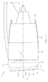
- the perforations 108 may be arranged into one or more arrays 114A, 114B as shown in FIG. 1 (see also FIG. 7 ), where a first of the arrays 114B is on the illustrated front side of the nacelle 24 and a second of the arrays 114A is on the hidden back side of the nacelle 24.
- the perforations 112 in each of these arrays 114A and 114B may be further arranged into one or more subarrays. Each array 114A, 114B of perforations 112 in FIGS.
- 1 and 7 for example, includes a forward subarray 116A, 116B of perforations 112, an intermediate subarray 118A, 118B of perforations 112 and an aft subarray 120A, 120B of perforations 112.
- each of the plenums 98A-100A, 98B-100B may be configured as a duct with, for example, one side thereof configured as a respective portion of the perforated outer skin 80.
- Each of the plenums 98A-100A, 98B-100B is thereby fluidly coupled with a plurality of the perforations 112 (see FIG. 8 ) in the outer barrel 58.
- the first plenums 98A, 98B are fluidly coupled with the forward subarrays 116A, 116B, respectively, of perforations 112.
- the second plenums 99A, 99B are fluidly coupled with the intermediate subarrays 118A, 118B, respectively, of perforations 112.
- the third plenums 100A, 100B are fluidly coupled with the aft subarrays 120A, 120B, respectively, of perforations 112.
- the first and the second plenums 98A and 99A, 98B and 99B are located axially between a forward bulkhead 62 and an aft bulkhead 64, with the first plenum 98A, 98B axially forward of the second plenum 99A, 99B.
- the third plenum 100A, 100B is located axially between the aft bulkhead 64 and the aft end 82.
- the plenums 98A-100A, 98B-100B are respectively fluidly coupled with the suction sources 106A, 106B through the conduits 102A-104A, 102B-104B; e.g., ducts.
- Each suction source 106A, 106B may be configured as a pump or a vacuum with an electric motor; e.g., an electric pump.
- the suction sources 106A and 106B are not limited to the foregoing exemplary embodiments.
- Each suction source 106A, 106B is operable to draw boundary layer air flowing along the outer barrel 58 into the ALFC system 44 so as to actively promote laminar flow adjacent the nacelle 24.
- each suction source 106A, 106B is configured to draw boundary layer air flowing along the outer barrel 58 into the plenums through the array 114A, 114B of perforations 112. The air within the plenums 98A-100A, 98B-100B is then drawn into the suction source 106A, 106B through the conduits 102A-104A, 102B-104B, and is discharged from the suction source 106A, 106B through at least one outlet.
- the drain mechanisms 108A-110A, 108B-110B are respectively fluidly coupled with and between the perforations 112 and the suction sources 106A, 106B.
- the each of the drain mechanisms 108A-110A, 108B-110B is configured with a respective one of the plenums 98A-100A, 98B-100B; see also FIG. 9 .
- a manifold conduit 105A, 105B for the respective conduits 102A-104A, 102B-104B may be configured with a respective drain mechanisms 140 as illustrated in FIG. 10 .
- liquid such as rain water, anti-ice fluid, etc. may contact the exterior surface of the outer barrel 58.
- Some of this liquid (hereinafter referred to as “rain water” of ease of description) may travel through the perforations 112 and into one or more of the plenums 98A-100A, 98B-100B.
- the drain mechanisms 108A-110A, 108B-110B may be located at gravitational low points in the ALFC system 44 and configured to selectively direct the rain water out of the ALFC system 44.
- each of the drain mechanisms 108A-110A, 108B-110B is configured to open (and may remain open) while the ALFC system 44 and, more particularly, the suction sources 106A, 106B are non-operational.
- Each of the drain mechanisms 108A-110A, 108B-110B is also configured to close (and may remain closed) while the ALFC system 44 and, more particularly, the suction sources 106A, 106B are operational.
- one or more of the drain mechanisms 108A-110A, 108B-110B may be configured as a passive drain mechanism 150.
- This drain mechanism 150 may be configured as a flapper valve, for example.
- the drain mechanism 150 includes a flap 152, which is adapted to open and remain open while there is no or relatively low suction / vacuum within the ALFC system 44; e.g., when its respective suction source is non-operational, just started, or just turned off.
- the drain mechanism 150 may also include a biasing device 154 (e.g., a spring) configured to bias the flap 152 open.
- the suction source when the suction source generates suction / vacuum above a certain (e.g., "activation") threshold within the ALFC system 44 (less than the typical operational suction level), the pressure differential across the opening 156 in the drain mechanism 150 may cause the flap 152 to swing closed and remain closed.
- a certain threshold e.g., "activation" threshold within the ALFC system 44 (less than the typical operational suction level)
- the pressure differential across the opening 156 in the drain mechanism 150 may cause the flap 152 to swing closed and remain closed.
- the ALFC system 44 may also or alternatively be configured with various other types of passive drain mechanisms (e.g., passive valves) other than the drain mechanism 150 described above.
- one or more of the drain mechanisms 108A-110A, 108B-110B may alternatively be configured as an active drain mechanism 160.
- This drain mechanism 160 may be configured as an electronically actuated drain valve, for example.
- the drain mechanism 160 may include an actuator 162 (e.g., an electric motor) configured to open and close a valve element 164 in response to receiving control signals from a controller 166.
- This controller 166 may be configured to synchronize the opening and closing of the drain mechanism 160 with operation of the ALFC system 44 and, more particularly, the operation of a respective one of the suction devices.
- the controller 166 may signal the actuator 162 to close the valve element 164 about when (e.g., just before, exactly when or just after) the suction device is turned on. The controller 166 may then signal the actuator 162 to open the valve element 166 about when (e.g., just before, exactly when or just after) the suction device is turned off. The controller 166, of course, may also be configured to signal the actuator 162 to open or close the valve element 166 during other select times of operation. Furthermore, the ALFC system 44 may also or alternatively be configured with various other types of active drain mechanisms (e.g., actives valves) other than the drain mechanism 160 described above.
- actives valves e.g., actives valves
- one or more of the drain mechanisms may direct the rain water out of the ALFC system 44 into an interior cavity 170, chamber or plenum in the nacelle inlet 42. This rain water may then drain out of the nacelle inlet 42 through a drainage aperture 172 in the outer barrel 58, which aperture 172 may be located at a gravitational low point of the outer barrel.
- a drainage aperture 172 may also drain liquid (e.g., rain water) which is directed into the cavity 170 from one or more of the acoustic panels 71 in the inner barrel 54 (see FIG. 3 ).
- the acoustic panels 71 may be configured with one or more other discrete drainage apertures.
- the conduits 102A, 103A and 104A may be positioned at a gravitational lowest point ("bottom") of each plenum 98A, 99A and 100A. With the conduits at the bottom of the plenums, when the system turns on, and assuming it can withstand liquids, the pump may ingest any trapped liquid and push it out of the outlet. Water may collect when the aircraft is on the ground or in the clouds, but will be evacuated by the vacuum source when the ALFC system turns on before the aircraft reaches higher altitudes and freezing temperatures.
- the ALFC system 44 of the present disclosure is not limited to the exemplary configurations described above.
- the ALFC system 44 may be configured with a single suction source, or additional suction sources; e.g., one for each plenum.
- the ALFC system 44 may be configured with additional plenums, or one or more of the plenums described above may be omitted.
- One or more of the plenums as well as one or more of the conduits may be configured with its own drain mechanism or multiple drain mechanisms.
- the inlet nacelle may be configured as a generally unitary structure, or alternatively configured with opposing "gull-wing" door structures.
- One or more sets of the plenums 98A-B, 99A-B, 100A-B may be fluidly coupled and/or integrated into a single circumferentially extending plenum.
- a plenum may extend, for example, between one-hundred and eighty degrees (180°) to completely around the axis 36.
- ALFC system 44 configurations may be implemented with the nacelle inlet 42 of the present disclosure.
Landscapes
- Engineering & Computer Science (AREA)
- Aviation & Aerospace Engineering (AREA)
- Chemical & Material Sciences (AREA)
- Combustion & Propulsion (AREA)
- Structures Of Non-Positive Displacement Pumps (AREA)
Abstract
Description
- This disclosure relates generally to an aircraft propulsion system and, more particularly, to a nacelle for an aircraft propulsion system and a system for promoting laminar flow over portions of the nacelle to reduce drag.
- It is generally known that laminar flow over an aerodynamic surface, such as an outer surface of a nacelle of an aircraft propulsion system, reduces drag compared to turbulent flow over the same surface. To promote such laminar flow, various active laminar flow control (ALFC) systems have been conceptually developed. Such an ALFC system may include a plenum duct positioned at least partly inside of the nacelle. This plenum duct is fluidly coupled with perforations in the outer surface. The plenum duct is also fluidly coupled with a suction means, which draws air into the plenum duct through the perforations in the outer surface in order to modify airflow over the outer surface. This modification generally removes low energy air from a boundary layer along an extent of the outer surface to prevent that boundary layer from thickening and eventually tripping into a turbulent flow.
- While ALFC systems have various known advantages, these systems are typically difficult to commercially implement due to various deficiencies. There is a need in the art therefore for an improved active laminar flow control (ALFC) system.
- According to an aspect of the present disclosure, a nacelle is provided for an aircraft propulsion system. This nacelle includes an outer barrel and an active laminar flow control system. The active laminar flow control system includes an array of perforations in the outer barrel, a suction source and a drain mechanism. The suction source is fluidly coupled with the array of perforations. The drain mechanism is fluidly coupled with and between the array of perforations and the suction source.
- According to another aspect of the present disclosure, another nacelle is provided for an aircraft propulsion system. This nacelle includes a nacelle inlet and an active laminar flow control system. The nacelle inlet includes an inner barrel and an outer barrel circumscribing the inner barrel. The inner barrel includes a sound attenuating acoustic panel. The active laminar flow control system includes a plurality of arrays of perforations in the outer barrel, a suction source and a drain mechanism. The suction source is fluidly coupled with the arrays of perforations. The drain mechanism is fluidly coupled with and between at least one of the arrays of perforations and the suction source.
- According to still another aspect of the present disclosure, another nacelle is provided for an aircraft propulsion system. This nacelle includes a nacelle inlet and an active laminar flow control system. The nacelle inlet includes and an outer barrel circumscribing the inner barrel. The inner barrel includes a sound attenuating acoustic panel. The active laminar flow control system includes an array of perforations in the outer barrel, a suction device, a drain mechanism and a controller. The suction source is fluidly coupled with the array of perforations. The drain mechanism is fluidly coupled with and between the array of perforations and the suction source. The controller is configured to synchronize actuation of the drain mechanism with operation of the suction source.
- According to another aspect of the present disclosure, the nacelle inlet includes a noselip at the leading edge, an inner barrel coupled to the inner diameter of the noselip, and an outer barrel circumscribing the inner barrel and coupled to the outer diameter of the noselip. The noselip and outer barrel may be separate pieces attached together, or may be integrated together to form a one piece noselip and outer barrel (an extended noselip or inlet).
- The drain mechanism may be fluidly coupled with and between each of the arrays of perforations and the suction source.
- The drain mechanism may include or be configured as a passive drain mechanism. The drain mechanism may alternatively include or be configured as an active drain mechanism. This active drain mechanism may be actuated based on the operation of the suction source.
- The drain mechanism may be configured to close where the suction source is operational.
- The drain mechanism may be configured to open where the suction source is non-operational.
- The drain mechanism may include or be configured as a flapper valve. The flapper valve may include a flap and a biasing device configured to bias the flap in an open position.
- The drain mechanism may be electronically synchronized with the suction source such that the drain mechanism is open where the suction source is non-operational and such that the drain mechanism is closed where the suction source is operational.
- The active laminar control system may include a plenum and a conduit. The plenum may be configured with the outer barrel and is fluidly coupled with the array of perforations. The conduit may fluidly couple the plenum with the suction source. The drain mechanism may be configured with the plenum.
- The active laminar control system may include a plenum and a conduit. The plenum may be configured with the outer barrel and is fluidly coupled with the array of perforations. The conduit may fluidly couple the plenum with the suction source. The drain mechanism may be configured with the conduit.
- The active laminar control system may include a second array of perforations in the outer barrel which are fluidly coupled with the suction source. The drain mechanism may be fluidly coupled with and between the second array of perforations and the suction source.
- The active laminar control system may include a second array of perforations in the outer barrel, a second suction source and a second drain mechanism. The second suction source may be fluidly coupled with a second array of perforations. The second drain mechanism may be fluidly coupled with and between the second array of perforations and the second suction source.
- Aspects of the disclosure are directed to one or more arrays of perforations. An array may be fluidly coupled to a plenum. The plenum may be coupled to a suction source and a drain mechanism.
- The nacelle may include an inner barrel axially aligned with and radially within the outer barrel. The inner barrel may include one or more acoustic panels which are fluidly discrete from the active laminar control system.
- The drain mechanism may be configured to direct liquid out of the active laminar control system into a cavity within the nacelle. The outer barrel may have a drain aperture, which is configured to direct the liquid from within the cavity out of the nacelle.
- According to aspects of the disclosure, a nacelle inlet and an outer barrel are a single monolithic body.
- The foregoing features and the operation of the invention will become more apparent in light of the following description and the accompanying drawings.
-
-
FIG. 1 is a side view illustration of an aircraft propulsion system. -
FIG. 2 is a perspective side cutaway illustration of the aircraft propulsion system. -
FIG. 3 is a perspective side sectional illustration of a forward portion of a nacelle configured with an active laminar flow control (ALFC) system. -
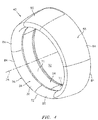
FIG. 4 is a perspective illustration of a nacelle inlet for the aircraft propulsion system. -
FIG. 5 is a front view illustration of the nacelle inlet. -
FIG. 6 is a side sectional illustration of a forward portion of another nacelle. -
FIG. 7 is a block diagram illustration of the forward portion of the nacelle configured with the ALFC system. -
FIG. 8 is a side sectional illustration of a portion of an outer barrel of the nacelle. -
FIG. 9 is a perspective side cutaway illustration of an embodiment of the forward portion of the nacelle with the ALFC system. -
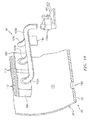
FIG. 10 is a perspective side cutaway illustration of another embodiment of the forward portion of the nacelle with the ALFC system. -
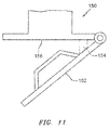
FIG. 11 is an illustration of a passive drain mechanism. -
FIG. 12 is a block diagram illustration of an active drain mechanism. - The present disclosure includes active laminar flow control (ALFC) systems for an aircraft and, more particularly, an aircraft propulsion system configured with the aircraft. As described below in further detail, these ALFC systems may be susceptible to ingesting / taking-in liquids such as rain water, deicing fluids, etc. while the aircraft is parked, taxiing, taking off or landing at an airport. These ALFC systems may also be susceptible to ingesting / taking-in such liquids while the aircraft is flying below certain altitudes; e.g., below the cloud-line.
- It is generally desirable to prevent liquids from pooling or collecting and staying inside of the ALFC system. This collected liquid may interfere with the active laminar flow control system. The collected liquid may prevent proper operation of, or decrease operational efficiency of, the active laminar flow control system. The collected liquid, for example, rain water or condensation, under severe weather conditions may also freeze, expand and thereby deform internal plumbing components (e.g., plenums, conduits, etc.) of the active laminar flow control system.
- To prevent or reduce collection of liquid(s), the ALFC systems disclosed below include one or more active drain mechanisms and/or one or more passive drain mechanisms. These drain mechanisms (e.g., valves, flow regulators, etc.) are operable to direct liquid out of the ALFC systems, typically while the ALFC systems are non-operational. The drain mechanisms may then close during at least some modes of ALFC system operation so as to prevent degradation to ALFC system operation and/or efficiency.
- Referring now to
FIGS. 1 and2 , anaircraft propulsion system 20 is illustrated that includes agas turbine engine 22 housed within anacelle 24. Theturbine engine 22 may be configured as a turbofan engine. Theturbine engine 22 ofFIG. 2 , for example, includes afan 26 and anengine core 28, which may include low and high pressure compressors, a combustor and high and low pressure turbines. - The
fan 26 is configured with an array of fan blades. These fan blades are housed within atubular fan case 30. Thefan case 30 is configured to provide an outer boundary for an axial portion of agas path 32 extending into thepropulsion system 20 from aninlet orifice 34 and through thefan 26. Thefan case 30 may also be configured to radially contain one or more of the fan blades and/or fan blade fragments where the blade(s) and/or blade fragment(s) are radially ejected from the fan rotor, for example, after collision with a foreign object. - The
nacelle 24 extends along anaxis 36 between a nacelleforward end 38 and a nacelle aftend 40. Thenacelle 24 includes anacelle inlet 42 configured with an active laminar flow control (ALFC)system 44; see alsoFIG. 3 . Thenacelle 24 also includes afan cowl 46 and anaft nacelle structure 48 which may be configured as a thrust reverser. Thecomponents axis 36 with thenacelle inlet 42 at the nacelleforward end 38 and with theaft nacelle structure 48 generally at the nacelle aftend 40. Thefan cowl 46 is generally axially aligned with thefan 26 and axially overlaps thefan case 30. - The
nacelle inlet 42 is configured to direct a stream of air through theinlet orifice 34 and into theturbine engine 22. More particularly, thenacelle inlet 42 is configured to provide a split between (A) air flowing into thegas path 32 through theinlet orifice 34 and (B) air flowing around and outside of thepropulsion system 20. Thenacelle inlet 42 may also be configured to create and/or maintain laminar flow of the air flowing outside and adjacent to thenacelle 24 as described below in further detail. By promoting and/or extending laminar flow, thenacelle inlet 42 may reduce aerodynamic drag and increasepropulsion system 20 efficiency. - Referring to
FIGS. 1 and3-5 , thenacelle inlet 42 includes a noselip 51 (seeFIG. 1 ) at the leading edge, a tubular acousticinner barrel 54, an annular inlet lip 56 (seeFIG. 3 ) and a tubularouter barrel 58, which may or may not be circumferentially interrupted by a pylon (not shown). Theinner barrel 54 extends circumferentially around theaxis 36. Theinner barrel 54 extends axially along theaxis 36 between an inner barrelforward end 68 and an inner barrelaft end 70. - The
inner barrel 54 may be configured to attenuate noise generated duringpropulsion system 20 operation and, more particularly for example, noise generated by rotation of thefan 26. Theinner barrel 54, for example, may include at least one tubular noise attenuating acoustic panel or an array of arcuate noise attenuatingacoustic panels 71 arranged around theaxis 36. Eachacoustic panel 71 may include a porous (e.g., honeycomb) core bonded between a perforated face sheet and a non-perforated back sheet, where the perforated face sheet faces radially inward and provides an outer boundary for an axial portion of thegas path 32. Each of theseacoustic panels 71 may be structurally and/or fluidly discrete from theALFC system 44. Of course, various other acoustic panel types and configurations are known in the art, and the present disclosure is not limited to any particular ones thereof. - The
inlet lip 56 forms a leadingedge 72 of thenacelle 24 as well as theinlet orifice 34 to thegas path 32. Theinlet lip 56 has a cupped (e.g., a generally U-shaped or V-shaped) cross-sectional geometry which extends circumferentially around theaxis 36. Theinlet lip 56 includes axially overlapping inner andouter lip portions FIG. 3 . - The
inner lip portion 74 extends axially from theouter lip portion 76 at the nacelleforward end 38 and theinlet orifice 34 to theinner barrel 54. Anaft end 78 of theinner lip portion 74 is attached to the inner barrel forward end 68 with, for example, one or more fasteners; e.g., rivets, bolts, etc. Theinner lip portion 74 may also or alternatively be bonded - (e.g., welded, brazed, adhered, etc.) to the
inner barrel 54. Of course, the present disclosure is not limited to any particular attachment techniques between theinlet lip 56 and theinner barrel 54. - The
outer lip portion 76 extends axially from theinner lip portion 74 at the nacelleforward end 38 to theouter barrel 58. Theouter lip portion 76 and, more particular, theentire inlet lip 56 may be formed integral with theouter barrel 58 as illustrated inFIG. 3 . Theinlet lip 56 and theouter barrel 58, for example, may be formed from a monolithicouter skin 80 such as, for example, a formed piece of sheet metal or molded composite material; e.g., fiber reinforcement within a polymer matrix. Such a monolithicouter skin 80 may extend longitudinally from theaft end 78 of theinner lip portion 74 to anaft end 82 of theouter barrel 58. - The
inlet lip 56 and theouter barrel 58 may be configured as a single monolithic full hoop body. Alternatively, theinlet lip 56 and theouter barrel 58 may be formed from an array of arcuate segments 84-86 that are attached side-to-side circumferentially about theaxis 36 as shown inFIGS. 4 and5 . In other embodiments, however, theinlet lip 56 may be formed discrete from theouter barrel 58, as shown inFIG. 6 . In such an embodiment, anaft end 88 of theouter lip portion 76 is attached (e.g., mechanically fastened and/or bonded) to a forward end 90 of theouter barrel 58. - Referring again to
FIG. 3 , theouter barrel 58 extends circumferentially around theaxis 36. Theouter barrel 58 is generally axially aligned with and circumscribes theinner barrel 54. Theouter barrel 58 extends axially along theaxis 36 between theinlet lip 56 and, more particularly, theouter lip portion 76 and the outer barrel aftend 82. - Referring to
FIGS. 3 and7 , the active laminar flow control (ALFC)system 44 includes one ormore plenums 98A-100A, 98B-100B, one ormore conduits 102A-104A, 102B-104B, one ormore suction sources more drain mechanisms 108A-110A, 108B-110B (shown in block form inFIG. 3 ). TheALFC system 44 also includes a plurality ofperforations 112 in thenacelle 24 and, more particularly for example, in theouter barrel 58. - The
perforations 112 extend through theouter skin 80 of theouter barrel 58 as shown inFIG. 8 . The perforations 108 may be arranged into one ormore arrays FIG. 1 (see alsoFIG. 7 ), where a first of thearrays 114B is on the illustrated front side of thenacelle 24 and a second of thearrays 114A is on the hidden back side of thenacelle 24. Theperforations 112 in each of thesearrays array perforations 112 inFIGS. 1 and7 , for example, includes aforward subarray perforations 112, anintermediate subarray perforations 112 and anaft subarray perforations 112. - Referring to
FIGS. 3 and7 , each of theplenums 98A-100A, 98B-100B may be configured as a duct with, for example, one side thereof configured as a respective portion of the perforatedouter skin 80. Each of theplenums 98A-100A, 98B-100B is thereby fluidly coupled with a plurality of the perforations 112 (seeFIG. 8 ) in theouter barrel 58. In particular, thefirst plenums forward subarrays perforations 112. Thesecond plenums intermediate subarrays perforations 112. Thethird plenums aft subarrays perforations 112. Referring toFIG. 3 , the first and thesecond plenums forward bulkhead 62 and anaft bulkhead 64, with thefirst plenum second plenum third plenum aft bulkhead 64 and theaft end 82. - Referring to
FIG. 7 , theplenums 98A-100A, 98B-100B are respectively fluidly coupled with thesuction sources conduits 102A-104A, 102B-104B; e.g., ducts. Eachsuction source suction sources suction source outer barrel 58 into theALFC system 44 so as to actively promote laminar flow adjacent thenacelle 24. More particularly, eachsuction source outer barrel 58 into the plenums through thearray perforations 112. The air within theplenums 98A-100A, 98B-100B is then drawn into thesuction source conduits 102A-104A, 102B-104B, and is discharged from thesuction source - The
drain mechanisms 108A-110A, 108B-110B are respectively fluidly coupled with and between theperforations 112 and thesuction sources FIG. 7 , for example, the each of thedrain mechanisms 108A-110A, 108B-110B is configured with a respective one of theplenums 98A-100A, 98B-100B; see alsoFIG. 9 . In addition or alternatively, amanifold conduit respective conduits 102A-104A, 102B-104B (or one or more of these conduits) may be configured with arespective drain mechanisms 140 as illustrated inFIG. 10 . - Under certain conditions, liquid such as rain water, anti-ice fluid, etc. may contact the exterior surface of the
outer barrel 58. Some of this liquid (hereinafter referred to as "rain water" of ease of description) may travel through theperforations 112 and into one or more of theplenums 98A-100A, 98B-100B. In order to prevent accumulation of such rain water within theALFC system 44, thedrain mechanisms 108A-110A, 108B-110B may be located at gravitational low points in theALFC system 44 and configured to selectively direct the rain water out of theALFC system 44. More particularly, each of thedrain mechanisms 108A-110A, 108B-110B is configured to open (and may remain open) while theALFC system 44 and, more particularly, thesuction sources drain mechanisms 108A-110A, 108B-110B is also configured to close (and may remain closed) while theALFC system 44 and, more particularly, thesuction sources - Referring to
FIG. 11 , one or more of thedrain mechanisms 108A-110A, 108B-110B (seeFIG. 7 ) may be configured as apassive drain mechanism 150. Thisdrain mechanism 150 may be configured as a flapper valve, for example. Thedrain mechanism 150 includes aflap 152, which is adapted to open and remain open while there is no or relatively low suction / vacuum within theALFC system 44; e.g., when its respective suction source is non-operational, just started, or just turned off. Thedrain mechanism 150 may also include a biasing device 154 (e.g., a spring) configured to bias theflap 152 open. However, when the suction source generates suction / vacuum above a certain (e.g., "activation") threshold within the ALFC system 44 (less than the typical operational suction level), the pressure differential across theopening 156 in thedrain mechanism 150 may cause theflap 152 to swing closed and remain closed. Of course, theALFC system 44 may also or alternatively be configured with various other types of passive drain mechanisms (e.g., passive valves) other than thedrain mechanism 150 described above. - Referring to
FIG. 12 , one or more of thedrain mechanisms 108A-110A, 108B-110B (seeFIG. 7 ) may alternatively be configured as anactive drain mechanism 160. Thisdrain mechanism 160 may be configured as an electronically actuated drain valve, for example. Thedrain mechanism 160 may include an actuator 162 (e.g., an electric motor) configured to open and close avalve element 164 in response to receiving control signals from acontroller 166. Thiscontroller 166 may be configured to synchronize the opening and closing of thedrain mechanism 160 with operation of theALFC system 44 and, more particularly, the operation of a respective one of the suction devices. For example, thecontroller 166 may signal theactuator 162 to close thevalve element 164 about when (e.g., just before, exactly when or just after) the suction device is turned on. Thecontroller 166 may then signal theactuator 162 to open thevalve element 166 about when (e.g., just before, exactly when or just after) the suction device is turned off. Thecontroller 166, of course, may also be configured to signal theactuator 162 to open or close thevalve element 166 during other select times of operation. Furthermore, theALFC system 44 may also or alternatively be configured with various other types of active drain mechanisms (e.g., actives valves) other than thedrain mechanism 160 described above. - Referring again to
FIG. 9 , one or more of the drain mechanisms (e.g., 108A and 109A inFIG. 9 ) may direct the rain water out of theALFC system 44 into aninterior cavity 170, chamber or plenum in thenacelle inlet 42. This rain water may then drain out of thenacelle inlet 42 through a drainage aperture 172 in theouter barrel 58, which aperture 172 may be located at a gravitational low point of the outer barrel. Such a drainage aperture 172 may also drain liquid (e.g., rain water) which is directed into thecavity 170 from one or more of theacoustic panels 71 in the inner barrel 54 (seeFIG. 3 ). Alternatively, theacoustic panels 71 may be configured with one or more other discrete drainage apertures. - Referring to
FIG. 10 , in some embodiments, there is no need for thedrain 140; e.g., thedrain 140 and/or other drains may be omitted. Instead, theconduits plenum - The
ALFC system 44 of the present disclosure, of course, is not limited to the exemplary configurations described above. For example, theALFC system 44 may be configured with a single suction source, or additional suction sources; e.g., one for each plenum. TheALFC system 44 may be configured with additional plenums, or one or more of the plenums described above may be omitted. One or more of the plenums as well as one or more of the conduits may be configured with its own drain mechanism or multiple drain mechanisms. The inlet nacelle may be configured as a generally unitary structure, or alternatively configured with opposing "gull-wing" door structures. One or more sets of theplenums 98A-B, 99A-B, 100A-B may be fluidly coupled and/or integrated into a single circumferentially extending plenum. Such a plenum may extend, for example, between one-hundred and eighty degrees (180°) to completely around theaxis 36. Of course, variousother ALFC system 44 configurations may be implemented with thenacelle inlet 42 of the present disclosure. - While various embodiments of the present invention have been disclosed, it will be apparent to those of ordinary skill in the art that many more embodiments and implementations are possible within the scope of the invention. For example, the present invention as described herein includes several aspects and embodiments that include particular features. Although these features may be described individually, it is within the scope of the present invention that some or all of these features may be combined with any one of the aspects and remain within the scope of the invention. Accordingly, the present invention is not to be restricted except in light of the attached claims and their equivalents.
Claims (15)
- A nacelle (24) for an aircraft propulsion system (20), comprising:an outer barrel (58); andan active laminar flow control system (44) including an array of perforations (112) in the outer barrel (58), a suction source (106A, 106B) and a drain mechanism,;wherein the suction source (106A, 106B) is fluidly coupled with the array of perforations (112); andwherein the drain mechanism (108A-110A, 108B-110B) is fluidly coupled with and between the array of perforations (112) and the suction source (106A-106B).
- The nacelle of claim 1, wherein the drain mechanism (108A-110A, 108B-110B) is configured to close where the suction source is operational; and optionally wherein the drain mechanism (108A-110A), 108B-110B) is configured to open where the suction source (106A, 106B) is non-operational
- The nacelle of claim 1 or 2, wherein the drain mechanism (108A-110A, 108B-110B) is a passive drain mechanism, or wherein the drain mechanism (108A-110A, 108B-110B) is an active drain mechanism.
- The nacelle of any preceding claim, wherein the drain mechanism (108A-110A, 108B-110B) comprises a flapper valve, and optionally wherein the flapper valve includes a flap and a biasing device configured to bias the flap in an open position.
- The nacelle of any preceding claim, wherein the drain mechanism (108A-110A, 108B-110B) is electronically synchronized with the suction source (106A, 106B) such that the drain mechanism (108A-110A, 108B-110B) is open where the suction source (106A, 106B) is non-operational and such that the drain mechanism (108A-110A, 108B-110B) is closed where the suction source (106A, 106B) is operational.
- The nacelle of any preceding claim, wherein
the active laminar control system (44) further includes a plenum (98A, 99A) and a conduit (102A, 103 A);
the plenum (98A, 99A) is configured with the outer barrel (58) and is fluidly coupled with the array of perforations (112);
the conduit (102A, 103A) fluidly couples the plenum (98A, 99A) with the suction source (106A, 106B); and
the drain mechanism is configured with the plenum (98A, 99A), or the drain mechanism is configured with the conduit (102A, 103A). - The nacelle of any preceding claim, wherein
the active laminar control system (44) further includes a second array of perforations in the outer barrel (58) which are fluidly coupled with the suction source (106A); and
the drain mechanism is fluidly coupled with and between the second array of perforations and the suction source (106B). - The nacelle of any preceding claim, wherein
the active laminar control system further includes a second array of perforations in the outer barrel (58), a second suction source (106B) and a second drain mechanism (108B-110B);
the second suction source (106B) is fluidly coupled with second array of perforations; and
the second drain mechanism (108B-110B) is fluidly coupled with and between the second array of perforations and the second suction source (106B). - The nacelle of any preceding claim, further comprising an inner barrel (54) axially aligned with and radially within the outer barrel (58), wherein the inner barrel (54) includes one or more acoustic panels which are fluidly discrete from the active laminar control system (44).
- The nacelle of any preceding claim, wherein the drain mechanism (108A-110A, 108B-110B) is configured to direct liquid out of the active laminar control system (44) into a cavity (170) within the nacelle, and the outer barrel has a drain aperture which is configured to direct the liquid from within the cavity out of the nacelle (24).
- A nacelle (24) for an aircraft propulsion system (20) of any preceding claim, comprising:a nacelle inlet (42) including an inner barrel (54) and said outer barrel (58) circumscribing the inner barrel (54), the inner barrel (54) including a sound attenuating acoustic panel; andsaid active laminar flow control system (44) including a plurality of said arrays of perforations (112) in the outer barrel (58);wherein the suction source (106A, 106B) is fluidly coupled with the arrays of perforations (112); andwherein the drain mechanism (108A-110A, 108B-110B) is fluidly coupled with and between at least one of the arrays of perforations (112) and the suction source (106a, 106B).
- The nacelle of claim 10, wherein the drain mechanism (108A-110A, 108B-110B) is fluidly coupled with and between each of the arrays of perforations (112) and the suction source (106A, 106B).
- The nacelle of any preceding claim, wherein the drain mechanism (108A-110A, 108B-110B) comprises a passive drain mechanism, or wherein the drain mechanism (108A-110A, 108B-110B) comprises an active drain mechanism which is actuated based on the operation of the suction source (106A, 106B).
- The nacelle of any of claims 10 to 13, wherein the nacelle inlet (42) and the outer barrel (58) are a single monolithic body.
- A nacelle (24) for an aircraft propulsion system (20) of any preceding claim, comprising:a nacelle inlet (42) including an inner barrel (54) and said outer barrel (58) circumscribing the inner barrel (54), the inner barrel (54) including a sound attenuating acoustic panel; andsaid active laminar flow control system (44) further including a controller;wherein the controller (166) is configured to synchronize actuation of the drain mechanism (108A-110A, 108B-110B) with operation of the suction source (106A, 106B).
Applications Claiming Priority (1)
| Application Number | Priority Date | Filing Date | Title |
|---|---|---|---|
| US14/861,767 US20170081020A1 (en) | 2015-09-22 | 2015-09-22 | Active laminar flow control system with drainage |
Publications (2)
| Publication Number | Publication Date |
|---|---|
| EP3147206A1 true EP3147206A1 (en) | 2017-03-29 |
| EP3147206B1 EP3147206B1 (en) | 2019-11-06 |
Family
ID=56997338
Family Applications (1)
| Application Number | Title | Priority Date | Filing Date |
|---|---|---|---|
| EP16190075.8A Active EP3147206B1 (en) | 2015-09-22 | 2016-09-22 | Active laminar flow control system with drainage |
Country Status (2)
| Country | Link |
|---|---|
| US (1) | US20170081020A1 (en) |
| EP (1) | EP3147206B1 (en) |
Families Citing this family (11)
| Publication number | Priority date | Publication date | Assignee | Title |
|---|---|---|---|---|
| US10823061B2 (en) * | 2016-07-15 | 2020-11-03 | General Electric Company | Engine air inlet having a double-panel heated wall |
| US10723445B2 (en) | 2017-05-16 | 2020-07-28 | Rohr, Inc. | Strake for aircraft propulsion system nacelle |
| US11433990B2 (en) * | 2018-07-09 | 2022-09-06 | Rohr, Inc. | Active laminar flow control system with composite panel |
| US11136131B2 (en) | 2018-07-11 | 2021-10-05 | Goodrich Corporation | Ice protection system for a component of an aerodynamic system |
| US11332235B2 (en) * | 2018-07-16 | 2022-05-17 | The Boeing Company | Active flow control systems for aircraft and related methods |
| US11560843B2 (en) | 2020-02-25 | 2023-01-24 | General Electric Company | Frame for a heat engine |
| US11326519B2 (en) | 2020-02-25 | 2022-05-10 | General Electric Company | Frame for a heat engine |
| US11255264B2 (en) | 2020-02-25 | 2022-02-22 | General Electric Company | Frame for a heat engine |
| US11408349B2 (en) * | 2020-08-14 | 2022-08-09 | Raytheon Technologies Corporation | Active flow control transpirational flow acoustically lined guide vane |
| US11512608B2 (en) | 2020-08-14 | 2022-11-29 | Raytheon Technologies Corporation | Passive transpirational flow acoustically lined guide vane |
| CN117818871B (en) * | 2024-03-04 | 2024-05-17 | 中国空气动力研究与发展中心高速空气动力研究所 | Application method of passive mixed laminar flow nacelle |
Citations (3)
| Publication number | Priority date | Publication date | Assignee | Title |
|---|---|---|---|---|
| US4749150A (en) * | 1985-12-24 | 1988-06-07 | Rohr Industries, Inc. | Turbofan duct with noise suppression and boundary layer control |
| US6068328A (en) * | 1997-11-25 | 2000-05-30 | Gazdzinski; Robert F. | Vehicular boundary layer control system and method |
| EP3093236A1 (en) * | 2015-05-15 | 2016-11-16 | Rohr, Inc. | Multi-zone active laminar flow control system for an aircraft propulsion system |
Family Cites Families (5)
| Publication number | Priority date | Publication date | Assignee | Title |
|---|---|---|---|---|
| US5136837A (en) * | 1990-03-06 | 1992-08-11 | General Electric Company | Aircraft engine starter integrated boundary bleed system |
| US5297765A (en) * | 1992-11-02 | 1994-03-29 | Rohr, Inc. | Turbine engine nacelle laminar flow control arrangement |
| US7331421B2 (en) * | 2005-03-30 | 2008-02-19 | The Boeing Company | Flow restrictors for aircraft inlet acoustic treatments, and associated systems and methods |
| US7857257B2 (en) * | 2006-09-01 | 2010-12-28 | United Technologies Corporation | Aircraft thermal management system with reduced exhaust re-ingestion |
| US8752795B2 (en) * | 2010-11-23 | 2014-06-17 | John Ralph Stewart, III | Inlet nose cowl with a locally thickened fastening portion to enable an uninterrupted airflow surface |
-
2015
- 2015-09-22 US US14/861,767 patent/US20170081020A1/en not_active Abandoned
-
2016
- 2016-09-22 EP EP16190075.8A patent/EP3147206B1/en active Active
Patent Citations (3)
| Publication number | Priority date | Publication date | Assignee | Title |
|---|---|---|---|---|
| US4749150A (en) * | 1985-12-24 | 1988-06-07 | Rohr Industries, Inc. | Turbofan duct with noise suppression and boundary layer control |
| US6068328A (en) * | 1997-11-25 | 2000-05-30 | Gazdzinski; Robert F. | Vehicular boundary layer control system and method |
| EP3093236A1 (en) * | 2015-05-15 | 2016-11-16 | Rohr, Inc. | Multi-zone active laminar flow control system for an aircraft propulsion system |
Also Published As
| Publication number | Publication date |
|---|---|
| EP3147206B1 (en) | 2019-11-06 |
| US20170081020A1 (en) | 2017-03-23 |
Similar Documents
| Publication | Publication Date | Title |
|---|---|---|
| EP3147206B1 (en) | Active laminar flow control system with drainage | |
| US8646723B2 (en) | Device for connecting an air inlet with an aircraft nacelle actuator assembly | |
| US9969499B2 (en) | Nacelle for an aircraft turbojet engine with an extended front lip | |
| US8128037B2 (en) | Apparatus and method for passive purging of micro-perforated aerodynamic surfaces | |
| US8192147B2 (en) | Nacelle assembly having inlet bleed | |
| EP3093240B1 (en) | Nacelle inlet with extended outer barrel | |
| US10486821B2 (en) | Jet engine anti-icing and noise-attenuating air inlets | |
| US9908620B2 (en) | Multi-zone active laminar flow control system for an aircraft propulsion system | |
| CN102307783B (en) | Panels especially suitable for acoustic treatment of aircraft nacelle air inlets | |
| US9133790B2 (en) | Aircraft propulsion system provided with reverse thrust means | |
| US11390393B2 (en) | Nacelle with a translatable inlet for an aircraft propulsion system | |
| US20150030446A1 (en) | Nacelle for an aircraft bypass turbojet engine | |
| EP3594127B1 (en) | Active laminar flow control system with composite panel | |
| US20200108942A1 (en) | Nacelle inlet with reinforcement structure | |
| EP3441601A1 (en) | Turbine engine thrust reverser stop | |
| EP3628596B1 (en) | Active laminar flow control plenum panel arrangements and installation methods | |
| US20220042454A1 (en) | Nacelle air intake with an acoustic panel | |
| US11667387B2 (en) | Ice protection and boundary layer suction system for an aircraft aerofoil | |
| US9650992B2 (en) | Core cowl thrust reverser system and apparatus | |
| RU2803661C2 (en) | Nacelle air intake with acoustic panel | |
| EP3632791A1 (en) | Nacelle inlet with reinforcement structure |
Legal Events
| Date | Code | Title | Description |
|---|---|---|---|
| PUAI | Public reference made under article 153(3) epc to a published international application that has entered the european phase |
Free format text: ORIGINAL CODE: 0009012 |
|
| STAA | Information on the status of an ep patent application or granted ep patent |
Free format text: STATUS: THE APPLICATION HAS BEEN PUBLISHED |
|
| AK | Designated contracting states |
Kind code of ref document: A1 Designated state(s): AL AT BE BG CH CY CZ DE DK EE ES FI FR GB GR HR HU IE IS IT LI LT LU LV MC MK MT NL NO PL PT RO RS SE SI SK SM TR |
|
| AX | Request for extension of the european patent |
Extension state: BA ME |
|
| STAA | Information on the status of an ep patent application or granted ep patent |
Free format text: STATUS: REQUEST FOR EXAMINATION WAS MADE |
|
| 17P | Request for examination filed |
Effective date: 20170928 |
|
| RBV | Designated contracting states (corrected) |
Designated state(s): AL AT BE BG CH CY CZ DE DK EE ES FI FR GB GR HR HU IE IS IT LI LT LU LV MC MK MT NL NO PL PT RO RS SE SI SK SM TR |
|
| GRAP | Despatch of communication of intention to grant a patent |
Free format text: ORIGINAL CODE: EPIDOSNIGR1 |
|
| STAA | Information on the status of an ep patent application or granted ep patent |
Free format text: STATUS: GRANT OF PATENT IS INTENDED |
|
| INTG | Intention to grant announced |
Effective date: 20190605 |
|
| GRAS | Grant fee paid |
Free format text: ORIGINAL CODE: EPIDOSNIGR3 |
|
| GRAA | (expected) grant |
Free format text: ORIGINAL CODE: 0009210 |
|
| STAA | Information on the status of an ep patent application or granted ep patent |
Free format text: STATUS: THE PATENT HAS BEEN GRANTED |
|
| AK | Designated contracting states |
Kind code of ref document: B1 Designated state(s): AL AT BE BG CH CY CZ DE DK EE ES FI FR GB GR HR HU IE IS IT LI LT LU LV MC MK MT NL NO PL PT RO RS SE SI SK SM TR |
|
| REG | Reference to a national code |
Ref country code: GB Ref legal event code: FG4D |
|
| REG | Reference to a national code |
Ref country code: CH Ref legal event code: EP Ref country code: AT Ref legal event code: REF Ref document number: 1198421 Country of ref document: AT Kind code of ref document: T Effective date: 20191115 |
|
| REG | Reference to a national code |
Ref country code: IE Ref legal event code: FG4D |
|
| REG | Reference to a national code |
Ref country code: DE Ref legal event code: R096 Ref document number: 602016023668 Country of ref document: DE |
|
| REG | Reference to a national code |
Ref country code: NL Ref legal event code: MP Effective date: 20191106 |
|
| REG | Reference to a national code |
Ref country code: LT Ref legal event code: MG4D |
|
| PG25 | Lapsed in a contracting state [announced via postgrant information from national office to epo] |
Ref country code: PT Free format text: LAPSE BECAUSE OF FAILURE TO SUBMIT A TRANSLATION OF THE DESCRIPTION OR TO PAY THE FEE WITHIN THE PRESCRIBED TIME-LIMIT Effective date: 20200306 Ref country code: BG Free format text: LAPSE BECAUSE OF FAILURE TO SUBMIT A TRANSLATION OF THE DESCRIPTION OR TO PAY THE FEE WITHIN THE PRESCRIBED TIME-LIMIT Effective date: 20200206 Ref country code: FI Free format text: LAPSE BECAUSE OF FAILURE TO SUBMIT A TRANSLATION OF THE DESCRIPTION OR TO PAY THE FEE WITHIN THE PRESCRIBED TIME-LIMIT Effective date: 20191106 Ref country code: NL Free format text: LAPSE BECAUSE OF FAILURE TO SUBMIT A TRANSLATION OF THE DESCRIPTION OR TO PAY THE FEE WITHIN THE PRESCRIBED TIME-LIMIT Effective date: 20191106 Ref country code: SE Free format text: LAPSE BECAUSE OF FAILURE TO SUBMIT A TRANSLATION OF THE DESCRIPTION OR TO PAY THE FEE WITHIN THE PRESCRIBED TIME-LIMIT Effective date: 20191106 Ref country code: PL Free format text: LAPSE BECAUSE OF FAILURE TO SUBMIT A TRANSLATION OF THE DESCRIPTION OR TO PAY THE FEE WITHIN THE PRESCRIBED TIME-LIMIT Effective date: 20191106 Ref country code: LV Free format text: LAPSE BECAUSE OF FAILURE TO SUBMIT A TRANSLATION OF THE DESCRIPTION OR TO PAY THE FEE WITHIN THE PRESCRIBED TIME-LIMIT Effective date: 20191106 Ref country code: NO Free format text: LAPSE BECAUSE OF FAILURE TO SUBMIT A TRANSLATION OF THE DESCRIPTION OR TO PAY THE FEE WITHIN THE PRESCRIBED TIME-LIMIT Effective date: 20200206 Ref country code: GR Free format text: LAPSE BECAUSE OF FAILURE TO SUBMIT A TRANSLATION OF THE DESCRIPTION OR TO PAY THE FEE WITHIN THE PRESCRIBED TIME-LIMIT Effective date: 20200207 Ref country code: LT Free format text: LAPSE BECAUSE OF FAILURE TO SUBMIT A TRANSLATION OF THE DESCRIPTION OR TO PAY THE FEE WITHIN THE PRESCRIBED TIME-LIMIT Effective date: 20191106 |
|
| PG25 | Lapsed in a contracting state [announced via postgrant information from national office to epo] |
Ref country code: IS Free format text: LAPSE BECAUSE OF FAILURE TO SUBMIT A TRANSLATION OF THE DESCRIPTION OR TO PAY THE FEE WITHIN THE PRESCRIBED TIME-LIMIT Effective date: 20200306 Ref country code: HR Free format text: LAPSE BECAUSE OF FAILURE TO SUBMIT A TRANSLATION OF THE DESCRIPTION OR TO PAY THE FEE WITHIN THE PRESCRIBED TIME-LIMIT Effective date: 20191106 Ref country code: RS Free format text: LAPSE BECAUSE OF FAILURE TO SUBMIT A TRANSLATION OF THE DESCRIPTION OR TO PAY THE FEE WITHIN THE PRESCRIBED TIME-LIMIT Effective date: 20191106 |
|
| PG25 | Lapsed in a contracting state [announced via postgrant information from national office to epo] |
Ref country code: AL Free format text: LAPSE BECAUSE OF FAILURE TO SUBMIT A TRANSLATION OF THE DESCRIPTION OR TO PAY THE FEE WITHIN THE PRESCRIBED TIME-LIMIT Effective date: 20191106 |
|
| PG25 | Lapsed in a contracting state [announced via postgrant information from national office to epo] |
Ref country code: DK Free format text: LAPSE BECAUSE OF FAILURE TO SUBMIT A TRANSLATION OF THE DESCRIPTION OR TO PAY THE FEE WITHIN THE PRESCRIBED TIME-LIMIT Effective date: 20191106 Ref country code: EE Free format text: LAPSE BECAUSE OF FAILURE TO SUBMIT A TRANSLATION OF THE DESCRIPTION OR TO PAY THE FEE WITHIN THE PRESCRIBED TIME-LIMIT Effective date: 20191106 Ref country code: ES Free format text: LAPSE BECAUSE OF FAILURE TO SUBMIT A TRANSLATION OF THE DESCRIPTION OR TO PAY THE FEE WITHIN THE PRESCRIBED TIME-LIMIT Effective date: 20191106 Ref country code: RO Free format text: LAPSE BECAUSE OF FAILURE TO SUBMIT A TRANSLATION OF THE DESCRIPTION OR TO PAY THE FEE WITHIN THE PRESCRIBED TIME-LIMIT Effective date: 20191106 Ref country code: CZ Free format text: LAPSE BECAUSE OF FAILURE TO SUBMIT A TRANSLATION OF THE DESCRIPTION OR TO PAY THE FEE WITHIN THE PRESCRIBED TIME-LIMIT Effective date: 20191106 |
|
| REG | Reference to a national code |
Ref country code: DE Ref legal event code: R097 Ref document number: 602016023668 Country of ref document: DE |
|
| REG | Reference to a national code |
Ref country code: AT Ref legal event code: MK05 Ref document number: 1198421 Country of ref document: AT Kind code of ref document: T Effective date: 20191106 |
|
| PG25 | Lapsed in a contracting state [announced via postgrant information from national office to epo] |
Ref country code: SM Free format text: LAPSE BECAUSE OF FAILURE TO SUBMIT A TRANSLATION OF THE DESCRIPTION OR TO PAY THE FEE WITHIN THE PRESCRIBED TIME-LIMIT Effective date: 20191106 Ref country code: SK Free format text: LAPSE BECAUSE OF FAILURE TO SUBMIT A TRANSLATION OF THE DESCRIPTION OR TO PAY THE FEE WITHIN THE PRESCRIBED TIME-LIMIT Effective date: 20191106 |
|
| PLBE | No opposition filed within time limit |
Free format text: ORIGINAL CODE: 0009261 |
|
| STAA | Information on the status of an ep patent application or granted ep patent |
Free format text: STATUS: NO OPPOSITION FILED WITHIN TIME LIMIT |
|
| 26N | No opposition filed |
Effective date: 20200807 |
|
| PG25 | Lapsed in a contracting state [announced via postgrant information from national office to epo] |
Ref country code: AT Free format text: LAPSE BECAUSE OF FAILURE TO SUBMIT A TRANSLATION OF THE DESCRIPTION OR TO PAY THE FEE WITHIN THE PRESCRIBED TIME-LIMIT Effective date: 20191106 Ref country code: SI Free format text: LAPSE BECAUSE OF FAILURE TO SUBMIT A TRANSLATION OF THE DESCRIPTION OR TO PAY THE FEE WITHIN THE PRESCRIBED TIME-LIMIT Effective date: 20191106 |
|
| PG25 | Lapsed in a contracting state [announced via postgrant information from national office to epo] |
Ref country code: IT Free format text: LAPSE BECAUSE OF FAILURE TO SUBMIT A TRANSLATION OF THE DESCRIPTION OR TO PAY THE FEE WITHIN THE PRESCRIBED TIME-LIMIT Effective date: 20191106 |
|
| PG25 | Lapsed in a contracting state [announced via postgrant information from national office to epo] |
Ref country code: MC Free format text: LAPSE BECAUSE OF FAILURE TO SUBMIT A TRANSLATION OF THE DESCRIPTION OR TO PAY THE FEE WITHIN THE PRESCRIBED TIME-LIMIT Effective date: 20191106 |
|
| REG | Reference to a national code |
Ref country code: CH Ref legal event code: PL |
|
| REG | Reference to a national code |
Ref country code: BE Ref legal event code: MM Effective date: 20200930 |
|
| PG25 | Lapsed in a contracting state [announced via postgrant information from national office to epo] |
Ref country code: LU Free format text: LAPSE BECAUSE OF NON-PAYMENT OF DUE FEES Effective date: 20200922 |
|
| PG25 | Lapsed in a contracting state [announced via postgrant information from national office to epo] |
Ref country code: LI Free format text: LAPSE BECAUSE OF NON-PAYMENT OF DUE FEES Effective date: 20200930 Ref country code: IE Free format text: LAPSE BECAUSE OF NON-PAYMENT OF DUE FEES Effective date: 20200922 Ref country code: BE Free format text: LAPSE BECAUSE OF NON-PAYMENT OF DUE FEES Effective date: 20200930 Ref country code: CH Free format text: LAPSE BECAUSE OF NON-PAYMENT OF DUE FEES Effective date: 20200930 |
|
| PGFP | Annual fee paid to national office [announced via postgrant information from national office to epo] |
Ref country code: FR Payment date: 20210819 Year of fee payment: 6 |
|
| PGFP | Annual fee paid to national office [announced via postgrant information from national office to epo] |
Ref country code: GB Payment date: 20210820 Year of fee payment: 6 Ref country code: DE Payment date: 20210818 Year of fee payment: 6 |
|
| PG25 | Lapsed in a contracting state [announced via postgrant information from national office to epo] |
Ref country code: TR Free format text: LAPSE BECAUSE OF FAILURE TO SUBMIT A TRANSLATION OF THE DESCRIPTION OR TO PAY THE FEE WITHIN THE PRESCRIBED TIME-LIMIT Effective date: 20191106 Ref country code: MT Free format text: LAPSE BECAUSE OF FAILURE TO SUBMIT A TRANSLATION OF THE DESCRIPTION OR TO PAY THE FEE WITHIN THE PRESCRIBED TIME-LIMIT Effective date: 20191106 Ref country code: CY Free format text: LAPSE BECAUSE OF FAILURE TO SUBMIT A TRANSLATION OF THE DESCRIPTION OR TO PAY THE FEE WITHIN THE PRESCRIBED TIME-LIMIT Effective date: 20191106 |
|
| PG25 | Lapsed in a contracting state [announced via postgrant information from national office to epo] |
Ref country code: MK Free format text: LAPSE BECAUSE OF FAILURE TO SUBMIT A TRANSLATION OF THE DESCRIPTION OR TO PAY THE FEE WITHIN THE PRESCRIBED TIME-LIMIT Effective date: 20191106 |
|
| REG | Reference to a national code |
Ref country code: DE Ref legal event code: R119 Ref document number: 602016023668 Country of ref document: DE |
|
| GBPC | Gb: european patent ceased through non-payment of renewal fee |
Effective date: 20220922 |
|
| PG25 | Lapsed in a contracting state [announced via postgrant information from national office to epo] |
Ref country code: FR Free format text: LAPSE BECAUSE OF NON-PAYMENT OF DUE FEES Effective date: 20220930 Ref country code: DE Free format text: LAPSE BECAUSE OF NON-PAYMENT OF DUE FEES Effective date: 20230401 |
|
| PG25 | Lapsed in a contracting state [announced via postgrant information from national office to epo] |
Ref country code: GB Free format text: LAPSE BECAUSE OF NON-PAYMENT OF DUE FEES Effective date: 20220922 |