EP3147063A1 - Device and method for multichannel edm - Google Patents
Device and method for multichannel edm Download PDFInfo
- Publication number
- EP3147063A1 EP3147063A1 EP15186617.5A EP15186617A EP3147063A1 EP 3147063 A1 EP3147063 A1 EP 3147063A1 EP 15186617 A EP15186617 A EP 15186617A EP 3147063 A1 EP3147063 A1 EP 3147063A1
- Authority
- EP
- European Patent Office
- Prior art keywords
- electrode holder
- electrode
- electrical discharge
- current
- multichannel
- Prior art date
- Legal status (The legal status is an assumption and is not a legal conclusion. Google has not performed a legal analysis and makes no representation as to the accuracy of the status listed.)
- Granted
Links
Images



Classifications
-
- B—PERFORMING OPERATIONS; TRANSPORTING
- B23—MACHINE TOOLS; METAL-WORKING NOT OTHERWISE PROVIDED FOR
- B23H—WORKING OF METAL BY THE ACTION OF A HIGH CONCENTRATION OF ELECTRIC CURRENT ON A WORKPIECE USING AN ELECTRODE WHICH TAKES THE PLACE OF A TOOL; SUCH WORKING COMBINED WITH OTHER FORMS OF WORKING OF METAL
- B23H1/00—Electrical discharge machining, i.e. removing metal with a series of rapidly recurring electrical discharges between an electrode and a workpiece in the presence of a fluid dielectric
-
- B—PERFORMING OPERATIONS; TRANSPORTING
- B23—MACHINE TOOLS; METAL-WORKING NOT OTHERWISE PROVIDED FOR
- B23H—WORKING OF METAL BY THE ACTION OF A HIGH CONCENTRATION OF ELECTRIC CURRENT ON A WORKPIECE USING AN ELECTRODE WHICH TAKES THE PLACE OF A TOOL; SUCH WORKING COMBINED WITH OTHER FORMS OF WORKING OF METAL
- B23H1/00—Electrical discharge machining, i.e. removing metal with a series of rapidly recurring electrical discharges between an electrode and a workpiece in the presence of a fluid dielectric
- B23H1/02—Electric circuits specially adapted therefor, e.g. power supply, control, preventing short circuits or other abnormal discharges
- B23H1/028—Electric circuits specially adapted therefor, e.g. power supply, control, preventing short circuits or other abnormal discharges for multiple gap machining
-
- B—PERFORMING OPERATIONS; TRANSPORTING
- B23—MACHINE TOOLS; METAL-WORKING NOT OTHERWISE PROVIDED FOR
- B23H—WORKING OF METAL BY THE ACTION OF A HIGH CONCENTRATION OF ELECTRIC CURRENT ON A WORKPIECE USING AN ELECTRODE WHICH TAKES THE PLACE OF A TOOL; SUCH WORKING COMBINED WITH OTHER FORMS OF WORKING OF METAL
- B23H11/00—Auxiliary apparatus or details, not otherwise provided for
- B23H11/006—Electrical contacts or wires
-
- B—PERFORMING OPERATIONS; TRANSPORTING
- B23—MACHINE TOOLS; METAL-WORKING NOT OTHERWISE PROVIDED FOR
- B23H—WORKING OF METAL BY THE ACTION OF A HIGH CONCENTRATION OF ELECTRIC CURRENT ON A WORKPIECE USING AN ELECTRODE WHICH TAKES THE PLACE OF A TOOL; SUCH WORKING COMBINED WITH OTHER FORMS OF WORKING OF METAL
- B23H7/00—Processes or apparatus applicable to both electrical discharge machining and electrochemical machining
- B23H7/26—Apparatus for moving or positioning electrode relatively to workpiece; Mounting of electrode
-
- B—PERFORMING OPERATIONS; TRANSPORTING
- B23—MACHINE TOOLS; METAL-WORKING NOT OTHERWISE PROVIDED FOR
- B23H—WORKING OF METAL BY THE ACTION OF A HIGH CONCENTRATION OF ELECTRIC CURRENT ON A WORKPIECE USING AN ELECTRODE WHICH TAKES THE PLACE OF A TOOL; SUCH WORKING COMBINED WITH OTHER FORMS OF WORKING OF METAL
- B23H9/00—Machining specially adapted for treating particular metal objects or for obtaining special effects or results on metal objects
- B23H9/006—Cavity sinking
-
- B—PERFORMING OPERATIONS; TRANSPORTING
- B23—MACHINE TOOLS; METAL-WORKING NOT OTHERWISE PROVIDED FOR
- B23H—WORKING OF METAL BY THE ACTION OF A HIGH CONCENTRATION OF ELECTRIC CURRENT ON A WORKPIECE USING AN ELECTRODE WHICH TAKES THE PLACE OF A TOOL; SUCH WORKING COMBINED WITH OTHER FORMS OF WORKING OF METAL
- B23H2500/00—Holding and positioning of tool electrodes
Definitions
- the invention relates to an electrode holder for multichannel electrical discharge machining. Further the invention relates to an electrical discharge machine for a multichannel processing electrode holder.
- Multichannel machining consists in the electrical discharge machining (EDM) with a plurality of work pieces, or a plurality of electrodes, or both: a plurality of work pieces and a plurality of electrodes.
- EDM electrical discharge machining
- a plurality of individual discharge gaps are created, whereas each individual gap is served by a generator.
- the principle of multichannel machining has been proposed very early in the history of EDM, f.i. in US2783411 .
- Multichannel processing is of great relevance in the production environment, where it is essentially used to parallelize the process to the advantage of productivity.
- a multichannel EDM machine may have common or individual kinematic, process control and generator.
- Typical such cases are direct part production applications, where the processed part is not a casting mold but a final part of the production chain: drilling of injector nozzle holes, drilling of cooling holes for vanes and other turbine components, the texturing of rollers by electrical discharge texturing (EDT), etc.
- EDT electrical discharge texturing
- WEDM wire electrical discharge machining
- multichannel processing has been proposed for multi-wire slicing, for slot forming applications, etc.
- multichannel processing is also applicable with mold manufacturing.
- multichannel processing is also in the case of injection molding there is a steady trend to enhance production by increasing the parallelization, i.e. the number of casted parts produced by each injection cycle.
- multichannel processing is also of great relevance in with common standard electrical discharge machining applications.
- the engaged electrode surface area and thus the relevant capacitance is proportionally reduced.
- the electrically insulated partial electrodes are individually connected to the generator, so that the partial areas of the work piece are machined by the partial electrodes. With a smaller capacitance the wear of the electrode is reduced and improved process stability is achieved.
- multichannel processing is implemented with dedicated machines, specially designed to do always the same or similar specific task.
- a problem with such dedicated machines is that their manufacturing price is heavily determined by the market volume, becoming excessive with low quantities. Even worse, their design and development takes a lot of time, sometimes years, becoming risky for the manufacturer or investor.
- recently some applications have emerged in which it would be desirable to perform a multichannel processing with a plurality of universal electrical discharge machines.
- Certain molds are composed of arrays of similar or identical cavities and have very high requisites in terms of surface finish; in most cases it is comparably easy to divide an electrode into partial electrodes having same or similar partial area. As far as possible it would make sense to use universal electrical discharge machines, since these machines are flexible, do implement all required features and options, with the latest manufacturers technologies concerning generator, process control, machine design, etc.
- Object of the present invention is therefore to provide a device which makes it possible to facilitate the adaptation of standard electrical discharge machines for multichannel processing.
- the inventive electrode holder for multichannel electrical discharge machining can be used with an automatic electrode changer (ATC) and suitable electrode holders, to improve the productivity and/or enhance the surface quality.
- ATC automatic electrode changer
- a first aspect of the present invention is directed to electrode holder for multichannel electrical discharge machining, comprising:
- a second aspect of the present invention is directed to a die-sinking ED machine adapted for the best use of such a multichannel electrode holder, the die-sinking electric discharge machine being capable of supplying electric discharge pulses to a plurality of channels, and comprising a current brush assembly, whereas said assembly comprises a plurality of individual current supplying contactors for the supply of the machining current to a respective slip ring.
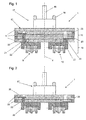
- the figure 1 illustrates schematically a possible embodiment of the electrode holder for multichannel electrical discharge machining according the invention.
- the inventive electrode holder 1 comprises holding elements 17 which are mounted on the top of a central body 15, and an electrode mounting section 19 which is located on the bottom of said central body 15. These constituent parts of the inventive electrode holder will now be described in detail.
- the inventive electrode holder 1 comprises on its top, the known and commonly used holding elements 17.
- the holding elements 17 have the function to hold the electrode holder 1 firmly and detachably fixed to a chuck (not shown) of the machining head in an electrical discharge machine.
- Part of the holding elements 17 are the so called referencing elements 16 by which the complete electrode holder 1 is precisely positioned on the machine head (not shown) of the electrical discharge machine.
- the electrode holder 1 further comprises manipulating elements (not shown) by which a fork gripper of an automatic tool changer can grasp the electrode holder 1 for automatic manipulation, e.g. from an electrode magazine to the machine head of an electrical discharge machine and vice versa.
- the holding elements comprise a drawbar 18 attached axially to the electrode holder 1, by which the electrode holder 1 is clamped in a chuck of the machine head.
- the referencing elements 16 are made according the state of the art, generally comprising vertical references (Z) in the form of stops, and separate horizontal references (X/Y) in the form of inset features provided in plates being partially elastic in Z direction. By said references 16 the precise and repeatable positioning of the electrode holder 1 with respect to the chuck is achieved.
- These holding elements 17 are not described in more detail since they are preferably of standard type, and are available from the known tooling system manufacturers. Additional details regarding the holding elements 17 are illustrated for instance in EP2361713A1 .
- the electrode holder 1 comprises at the base of the central body 15, an electrode mounting section 19 by which a plurality of electrical discharge machining electrodes 9, 10 are firmly and precisely positioned.
- the electrodes 9, 10, 11 are mounted in the desired position and are electrically insulated from each other by an air gap or by insulating elements (not shown).
- Said electrode mounting section 19 is divided in separate clamping sections 22, on which the electrodes 9, 10 are mounted.
- the clamping sections 22 can be adapted to the number, size and geometry of the used electrodes.
- the electrode holder 1 comprises a central body 15, with a plurality of separate internal current supplying circuits 20, being electrically insulated from each other, each circuit 20 leading from the periphery of the electrode holder 1 to a separate current feeder sector 21.
- the separate current feeder sectors 21 (not shown in detail) are embedded in the base of the central body 15 and represent the terminal of the separate internal current supplying circuits 20.
- the individual clamping sections 22 are fixedly mounted on individual current feeder sectors 21, f.i.by means of screws (not shown).
- the current feeder sector 21 may comprise movable contacting means to improve the contact with the clamping sections 22.
- the clamping sections 22 and current feeder sections 21 may be integrated to form one element.
- the current pulses provided by the generator of the electrical discharge machine are conducted to the electrode mounting section 19, to desired one of a plurality of electrodes used in the multichannel process.
- electrode mounting section is to be interpreted in the widest possible sense; for instance the electrodes may be clamped, screwed, soldered, etc. to the respective current feeder sectors located at the base of the central body.
- the electrode holder 1 for multichannel electrical discharge machining can comprise a plurality of slip rings 23 at its periphery.
- the slip rings 23 can have the form of a ring or of a ring sector and are located at the circular side of the electrode mounting section 19. In this way the slip rings 23 can be contacted by means of an external current feeder.
- Each slip ring 23 is connected to a separate current feeder sector 21 of the central body 15 and lastly to the individual electrodes 9, 10 by means of separate internal current supplying circuits 20. In this way the current pulses are conducted across the electrode holder 1 to the individual electrodes 9, 10.
- the electrode holder 1 has a slip ring 23 for each channel respectively each electrode 9, 10.
- the slip rings 23 constitute a part of the lateral surface of the electrode holder 1 respectively central body 15; here the slip rings 23 - of preferably same diameter - are stapled vertically and are coaxial aligned to the main axis of the electrode holder 1, electrically separated from each other, for instance by means of insulating discs 8. In this way the slip rings 23 can be contacted from the sides, for instance by means of current brushes or other means.
- the slip rings 23 may be arranged at the top surface 12 of the central body 15, just below or next to the referencing elements 16, as will be explained further down in respect of figure 6 .
- the slip rings 23 would essentially be arranged in the same plane and coaxial to the main axis Z of the electrode holder 1. They might still have the form of rings or ring sectors of different diameters, obviously suitably electrically separated from each other.
- an electrode holder for multichannel electrical discharge machining comprises at least the following elements:
- Most die-sinking electrical discharge machines comprise a C-axis, cinematically in series to a Z-axis.
- the electrode holder can be repositioned, for instance to compensate a misalignment of the electrodes with respect to the machine axes x, y or to set a desired angular position. It can also be used as a servo-controlled axis of the electrical discharge machine, for instance to execute a screw-type or helical machining in which the C- and Z-axis are simultaneously interpolated.
- the multichannel electrode holder can also be used to execute a machining in which the C- and Z-axis are simultaneously interpolated.
- Figure 4a and b show a sloped electrode 11, which is used to form the sloped slots in a cylindrical work piece, such as blisks, blings, or similar work pieces.
- An electrode holder according the invention may bear two or more such electrodes so as to improve the productivity.
- the electrode holder respectively its electrode mounting section which includes the slip rings has at least partially cylindrical form.
- a current brush can be easily brought in contact with the respective slip ring of the electrode holder to conduct the current pulses to the electrode.
- the cylindrical constitution of the central body By the cylindrical constitution of the central body, the rotation of the electrode in C-axis is possible. In this way the machining process can include rotational movement by the electrode holder.
- the central body 15 of the electrode holder comprises the internal current supplying circuits 20 and at both ends thereof it has the electrical contacting elements, i.e. slip rings 23 and current feeder sectors 21 by which current pulses are brought to the electrode mounting, respectively to the electrodes.
- the electrode mounting section comprises insulating elements, preferably having the shape of discs or rings. The electrical components and the insulating elements are mounted together to form a rigid body (compare figures).
- the holding elements 17 are located on top of the assembled central body 15 and on the opposite end - respectively at the bottom surface - of the central body 15 the electrode mounting section 19 is allocated with a plurality of mounted electrodes.
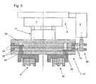
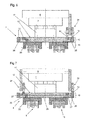
- Figures 1, 2 , 3 and 5 show different possible versions of electrode holders 1, 14 for multichannel electrical discharge machining according to the invention, in which the slip rings 23 are contacted radially by means of a current brush assembly 24.
- the central body of the electrode holder 1 is constituted by a sequence of axially piled layers, with slip rings 23 separated by insulating discs 26.
- the current brush assembly 24 comprises a brush 13 for each slip ring 23.
- the current brushes 13 are mounted on a current brush support 4 which is mounted on the machine head 6.
- the current brush support 4 comprises an actuator, f.i. a cylinder by which the brush assembly is a brought in contact with the slip rings 23 or withdrawn from them.
- the current brush assembly 24 comprises one or more springs to press the brushes against the according slip ring 23, to compensate possible concentricity errors of the slip rings 23 and/or to improve the electrical contact.
- the current brush assembly 24 is preferably mounted laterally to the machine head (or at the rear of the machine head), so that the other side of the machine head remains freely accessible to a gripper of an ATC, and the front side is freely accessible to the operator of the ED machine.
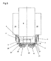
- the figures 6, 7 and 8 show another embodiment for an electrode holder for multichannel electrical discharge machining according to the invention.
- the slip rings 27 are mounted on the top surface 12 of the central body 15 of the electrode holder 2 and are contacted axially by brushes 13.
- the top surface 12 of the central body 15 of the electrode is constituted by a radial succession of slip ring 27 and insulating rings 26.
- the brushes 13 are straightly brought in contact to the slip rings 27 when the electrode holder 2 is positioned into the chuck 7 by means of an ATC or manually; thus with axial configuration of the current brush assembly 24 according figure 6, 7 or 8 there is no need for an additional actuator to contact and withdraw the brushes from the slip rings 27.
- the current brush assembly 24 is mounted at one side of the machining head 6.
- the current brushes 13 can also be split for instance as illustrated in the figure 7 :
- the current brush assemblies 24 are mounted at two sides of the machining head 6 to contact the slip rings 27 on the top surface 12 of the central body 15. In this way the forces exerted by the brushes 13 and springs to contact the slip rings 27 are homogeneously distributed and the electrode holder 2 is not subject to any additional torsion.
- the figure 8 shows a further possible configuration in which the electrode holder 2 for multichannel electrical discharge machining is used with a die-sinking EDM having a Z-axis with no C-axis.
- the design of the electrical connections may be further simplified by replacing the current brush assembly with a plug connector assembly 3 for automatic connection.
- the connection of the electrode holder 2 to the electrode cable 5 is established with the axial insertion of the electrode holder 2 into the clutch.
- an automatic tool changer moves the electrode holder 2 to the machining head 6, where the electrode holder 2 is clamped in a chuck 7 by means of the drawbar.
- a plug connector of the electrode holder is inserted in a socket connector which is fixedly and coaxially mounted on the machining head.
- two generator modules 28 are mounted at the left and right of the machining head 6 or on the housing of the machining head 6.
- One pole of the electrode cables 5 of each module is connected with a current brush assembly 24 by which the current pulses are conducted to the respective slip ring 27.
- the other poles are connected together to the work piece (not shown).
- the electrode cables 5 of the embodiment shown in figure 8 are very short, so that the effect of a distortion of the pulses is reduced.
- the components of the central body of the electrode holder for multichannel electrical discharge machining are made modular, i.e. slip rings 27, insulating rings 26 or insulating disks 26, the elements of the internal current supplying circuits 20 and other intermediate and interfacing components are designed in such a way that the electrode holder 1, 2 can be assembled in various configurations and thus extending the number of possible applications.
- the slip rings 27 comprise at least one protrusion to form as linking element a part of the internal current supplying circuit 20; said internal current supplying circuit 20 traverses the central body 15 of the electrode holder vertically, connecting electrically the slip rings 27 with the current feeder sectors 21 on the base of the central body 15.
- the protrusion respectively linking element is preferably a solid conductor of suitable length or a braid.
- the central body 15 of the electrode holder for multichannel electrical discharge machining must be rigid but not particularly accurate, since, as said the current brush assembly 24 comprises springs to press the brushes against the slip rings 23, 27.
- the manufacturing cost of the multichannel electrode holder 1 according to the invention is comparably low.
- the central body 15 must not be accurate due to the fact that the electrodes are machined on the electrode holder 1 itself. Thus only the rigidity of the electrode holder and the accuracy of the referencing elements are important, whereas the accuracy of the central body is not relevant for the manufacturing accuracy.
- the electrode holder for multichannel electrical discharge machining is provided in a basic configuration for two channels, and comprises further components to form a modular set.
- the electrode holder 1 for multichannel electrical discharge machining can be assembled to operate with the desired number of channels.
- said number is between two and four, but the electrode holder according the invention could also be used with a single channel, and, with more than 4 channels.
- the lowermost layer of the central body 15 is constituted as a terminal insulator disk 25 comprising the desired number of current feeder sectors 21. These sectors 21 are individually contacted by the internal current supplying circuits 20 of the central body 15 for each channel.
- the modular set comprises several exchangeable terminal insulator disks 25, each having a certain number of current feeder sectors 21 by which the current pulses are conducted to the clamping sections 22 and thus to the electrodes mounted thereon.
- the terminal disk 25 illustrated in figure 3 has four current feeder sectors 21 insulated from each other, by which the current is transmitted to the clamping sections 22 and to the electrodes, each sector at an angle of 90° from each other.
- the embodiments showed and explained in relation to the figures 5 , 6 , 7 and 8 have on the other hand each two current feeder sectors 21, two clamping sections 22 and two electrodes.
- the terminal insulator disk 25 of the electrode holder for multichannel electrical discharge machining could be made configurable, i.e. it is designed to fit for a variable number of electrodes and for the largest possible number of application cases.
- FIGS 9 and 10 show further advantageous embodiments of the electrode holder 1 for multichannel electrical discharge machining according to the invention.
- the central body 15 of the electrode holder 1 comprises a monolithic insulating element 30.
- the holding elements 17 are still are mounted on the top of the central body 15 and an electrode mounting section 19 is still located on the bottom of the central body 15.
- the central body 15 itself is no longer constituted by a sequence of axially piled layers, with slip rings 23 separated by insulating discs 26; in this simplified constitution a monolithic insulating element 30 bears the slip rings 23, the internal current supplying circuit 20 and the current feeder sectors 21.
- the slip rings 23 comprise at least one protrusion to form as linking element a part of the internal current supplying circuit 20, and the monolithic insulating element 30 comprises a plurality of notches on its periphery to accommodate the at least one protrusion of each slip ring 23, obviously at different notches.
- the monolithic insulating element 30 may comprise 4 notches distributed on its periphery, at 90° to each other, and each slip ring 23 has one protrusion. In this way the monolithic insulating element 30 can receive respectively bear up to 4 slip rings 23.
- the slip rings are inserted axially on the monolithic insulating element.
- the notches might have different depth so that the slip rings are positioned at a well-defined axial position on the monolithic insulating element 30.
- the notches may be continuous (through-notches), and the slip rings 23 may be axially separated by means of spacers and or by means of the internal current supplying circuit 20.
- the central body 15 described in the present embodiment is comparably simple and thus inexpensive, and thanks to the monolithic constitution of the insulating element it is even more rigid.
- the central body 15 comprises a monolithic insulating element 30 the electrode holder 1 still configurable for the desired number of channels, to a certain extent.
- the electrodes 9, 10 are first mounted to the clamping sections 22 of the electrode mounting section 19 of the multichannel electrode holder 1, 2, 14 in the desired configuration, and then they are directly machined altogether on said multichannel electrode holder 1, 2, 14.
- the relative positional accuracy of the plurality of electrodes mounted is not affected by a clamping operation, but is determined only by the machining accuracy of the machine tool used to prepare the electrodes.
- the relative position of the cavities generated by the EDM process is improved.
- the multichannel electrode holder bears at least two or more electrodes which are used in sequence with the same work piece.
- the electrodes are for instance a roughing and a finishing electrode.
- the process is not parallelized; the advantage lies in the fact that the electrodes are mounted on the same electrode holder and fabricated together on a milling machine or WEDM or other machine tool; in this way the accuracy of the process is no longer determined by clamping errors on both milling machine and EDM, but only by the accuracy of the manufacturing processes, and the capacitance is limited because the electrodes are electrically separated.
- a multichannel electrode holder configured to serve four channels has four separate internal current supplying circuits with four slip rings, four current feeder sectors and four clamping sections.
- Said multichannel electrode holder configured to serve four channels can also be use with less than four electrodes, i.e. three or two, but also with one single electrode if required.
- said multichannel electrode holder is configured to serve four channels but has only two electrodes, these two electrodes are mounted to separate sectors of electrode mounting section and current pulses are provided to only two slip rings of the current brush assembly.
- the present invention discloses a multichannel electrode holder which can be manipulated by means of an ATC with no particular restriction. Although all manufacturers of tooling systems have their own particular design, the multichannel electrode holder according the invention can be used with every specific system, by mounting the specific holding system 17 to the top of the central body 15. Thus it can be manipulated by means of a Robot or an ATC having a suitable gripper.
- the multichannel electrode holder disclosed in the present invention may further comprise auxiliary supplying circuits, for instance one or more supplying circuits for the processing liquid and/or compressed air, and/or cabling for sensing means for process monitoring.
- auxiliary supplying circuits may be designed to address each individual electrode of the multichannel electrode holder.
- connection for the processing liquid and compressed air may be common, typically trough the machining head of the EDM machine, or individual.
- the present invention is described in relation with an electrical discharge machining process. It is however understood that the same or similar features can be used with other electrical processes, such as electrochemical processes (in particular PECM), with hybrid processes, etc.
Landscapes
- Engineering & Computer Science (AREA)
- Mechanical Engineering (AREA)
- Chemical & Material Sciences (AREA)
- Chemical Kinetics & Catalysis (AREA)
- Electrochemistry (AREA)
- Physics & Mathematics (AREA)
- Thermal Sciences (AREA)
- Electrical Discharge Machining, Electrochemical Machining, And Combined Machining (AREA)
Abstract
Description
- The invention relates to an electrode holder for multichannel electrical discharge machining. Further the invention relates to an electrical discharge machine for a multichannel processing electrode holder.
- Multichannel machining according to the present invention consists in the electrical discharge machining (EDM) with a plurality of work pieces, or a plurality of electrodes, or both: a plurality of work pieces and a plurality of electrodes. Generally, a plurality of individual discharge gaps are created, whereas each individual gap is served by a generator. The principle of multichannel machining has been proposed very early in the history of EDM, f.i. in
US2783411 . Multichannel processing is of great relevance in the production environment, where it is essentially used to parallelize the process to the advantage of productivity. A multichannel EDM machine may have common or individual kinematic, process control and generator. - Typical such cases are direct part production applications, where the processed part is not a casting mold but a final part of the production chain: drilling of injector nozzle holes, drilling of cooling holes for vanes and other turbine components, the texturing of rollers by electrical discharge texturing (EDT), etc. In wire electrical discharge machining (WEDM) multichannel processing has been proposed for multi-wire slicing, for slot forming applications, etc.
However multichannel processing is also applicable with mold manufacturing. In fact, also in the case of injection molding there is a steady trend to enhance production by increasing the parallelization, i.e. the number of casted parts produced by each injection cycle. Thus, multichannel processing is also of great relevance in with common standard electrical discharge machining applications. - Beside the scope of process parallelization, in certain applications multichannel processing is suitable to achieve better technological results. It is known that a factor limiting the surface quality which can be obtained by EDM is the machining surface area. Moreover the machining surface area determines the electrode wear. This is due to the fact that the work piece and the electrode separated by an inter-electrode space (Gap) represent a capacitor which is part of the discharge circuit. The energy storage of said capacitor is proportional to the surface area of the electrode / work piece pairing. The main consequence is that with each voltage variation, especially at the beginning of the discharge, an unwanted additional current discharge adds to the desired discharge, thus changing its physical characteristics, the removal rate, electrode wear, and Gap distance. By dividing the electrode into electrically separated partial electrodes such as disclosed in
DE19540352 , the engaged electrode surface area and thus the relevant capacitance is proportionally reduced. The electrically insulated partial electrodes are individually connected to the generator, so that the partial areas of the work piece are machined by the partial electrodes. With a smaller capacitance the wear of the electrode is reduced and improved process stability is achieved. - The capacitance is calculated with the formula for plate capacitors, as follows:

where - C is the capacitance, in Farads;
- A is the electrode area, in square meters;
- εR is the dielectric constant of the processing liquid in the Gap;
- ε0 is the electric constant; and
- Gap is the inter-electrode distance, in meters;
- As said it is possible to provide more than one generator, for instance one for each partial electrode. The evolution of electronics leads to a steady higher generator power density and increased efficiency, so that the accommodation of the boards is simplified. Providing a plurality of machine integrated generators for multichannel die-sinking EDM becomes more and more interesting.
An even more effective use of the generator is possible if a generator is on during afraction 1/n (with n > 2) of the pulse period. In this case one can share the generator on-time between the channels, as described inEP2397250A1 For instance, if the on-time is less than 50%, then two channels can be served with one generator: during the pause of the first channel the generator is switched to the second channel so that the generator can be used by turns on one and the other discharge gap. - Usually multichannel processing is implemented with dedicated machines, specially designed to do always the same or similar specific task. A problem with such dedicated machines is that their manufacturing price is heavily determined by the market volume, becoming excessive with low quantities. Even worse, their design and development takes a lot of time, sometimes years, becoming risky for the manufacturer or investor. However, recently some applications have emerged in which it would be desirable to perform a multichannel processing with a plurality of universal electrical discharge machines.
- Certain molds are composed of arrays of similar or identical cavities and have very high requisites in terms of surface finish; in most cases it is comparably easy to divide an electrode into partial electrodes having same or similar partial area. As far as possible it would make sense to use universal electrical discharge machines, since these machines are flexible, do implement all required features and options, with the latest manufacturers technologies concerning generator, process control, machine design, etc.
- Object of the present invention is therefore to provide a device which makes it possible to facilitate the adaptation of standard electrical discharge machines for multichannel processing.
- The object is achieved by an electrode holder and an electrical discharge machine in accordance with the features of
claim 1. - The inventive electrode holder for multichannel electrical discharge machining can be used with an automatic electrode changer (ATC) and suitable electrode holders, to improve the productivity and/or enhance the surface quality.
- A first aspect of the present invention is directed to electrode holder for multichannel electrical discharge machining, comprising:
- holding elements by which the electrode holder is firmly and detachably fixed to a chuck of an electric discharge machine, and referencing elements by which the electrode holder is precisely positioned to said chuck;
- an electrode mounting section by which a plurality of electrical discharge machining electrodes are firmly and precisely mounted on the electrode holder;
- a central body, comprising a plurality of separate internal current supplying circuits, being electrically insulated from each other, each leading from the periphery of the electrode holder to a separate current feeder sector of the electrode mounting section.
- A second aspect of the present invention is directed to a die-sinking ED machine adapted for the best use of such a multichannel electrode holder, the die-sinking electric discharge machine being capable of supplying electric discharge pulses to a plurality of channels, and comprising a current brush assembly, whereas said assembly comprises a plurality of individual current supplying contactors for the supply of the machining current to a respective slip ring.
- Further aspects are set forth in the dependent claims, the following description and the drawings. Other features are inherent in the methods and products disclosed or will become apparent to those skilled in the art from the following detailed description of embodiments and its accompanying drawings.
- Embodiments of the invention will now be described, by way of example, and with reference to the accompanying drawings. The figures illustrate the following:
- Figs.1-3
- Partial sectional views of an electrode holder for multichannel electrical discharge machining according the invention
- Fig.4a,b
- A possible electrode shape
- Fig.5-8
- Partial views of the machining head of an ED machine bearing an electrode holder for multichannel electrical discharge machining according the invention
- Figs.9-10
- Partial sectional views of an electrode holder for multichannel electrical discharge machining according the invention
- The
figure 1 illustrates schematically a possible embodiment of the electrode holder for multichannel electrical discharge machining according the invention. Theinventive electrode holder 1 comprisesholding elements 17 which are mounted on the top of acentral body 15, and anelectrode mounting section 19 which is located on the bottom of saidcentral body 15. These constituent parts of the inventive electrode holder will now be described in detail. - The
inventive electrode holder 1 comprises on its top, the known and commonly used holdingelements 17. The holdingelements 17 have the function to hold theelectrode holder 1 firmly and detachably fixed to a chuck (not shown) of the machining head in an electrical discharge machine. Part of the holdingelements 17 are the so called referencingelements 16 by which thecomplete electrode holder 1 is precisely positioned on the machine head (not shown) of the electrical discharge machine. Theelectrode holder 1 further comprises manipulating elements (not shown) by which a fork gripper of an automatic tool changer can grasp theelectrode holder 1 for automatic manipulation, e.g. from an electrode magazine to the machine head of an electrical discharge machine and vice versa. The holding elements comprise adrawbar 18 attached axially to theelectrode holder 1, by which theelectrode holder 1 is clamped in a chuck of the machine head. The referencingelements 16 are made according the state of the art, generally comprising vertical references (Z) in the form of stops, and separate horizontal references (X/Y) in the form of inset features provided in plates being partially elastic in Z direction. By saidreferences 16 the precise and repeatable positioning of theelectrode holder 1 with respect to the chuck is achieved.
These holdingelements 17 are not described in more detail since they are preferably of standard type, and are available from the known tooling system manufacturers. Additional details regarding the holdingelements 17 are illustrated for instance inEP2361713A1 . - The
electrode holder 1 according the invention comprises at the base of thecentral body 15, anelectrode mounting section 19 by which a plurality of electricaldischarge machining electrodes electrodes electrode mounting section 19 is divided inseparate clamping sections 22, on which theelectrodes sections 22 can be adapted to the number, size and geometry of the used electrodes. - The
electrode holder 1 according to the invention comprises acentral body 15, with a plurality of separate internal current supplyingcircuits 20, being electrically insulated from each other, eachcircuit 20 leading from the periphery of theelectrode holder 1 to a separatecurrent feeder sector 21. The separate current feeder sectors 21 (not shown in detail) are embedded in the base of thecentral body 15 and represent the terminal of the separate internal current supplyingcircuits 20. Preferably, theindividual clamping sections 22 are fixedly mounted on individualcurrent feeder sectors 21, f.i.by means of screws (not shown). However thecurrent feeder sector 21 may comprise movable contacting means to improve the contact with the clampingsections 22. In a possible embodiment the clampingsections 22 andcurrent feeder sections 21 may be integrated to form one element. The current pulses provided by the generator of the electrical discharge machine (not displayed) are conducted to theelectrode mounting section 19, to desired one of a plurality of electrodes used in the multichannel process. Here the term "electrode mounting section" is to be interpreted in the widest possible sense; for instance the electrodes may be clamped, screwed, soldered, etc. to the respective current feeder sectors located at the base of the central body. - In a preferred embodiment of the invention, which is also illustrated in
figure 1 , theelectrode holder 1 for multichannel electrical discharge machining can comprise a plurality ofslip rings 23 at its periphery. In accordance with the illustrated embodiment, the slip rings 23 can have the form of a ring or of a ring sector and are located at the circular side of theelectrode mounting section 19. In this way the slip rings 23 can be contacted by means of an external current feeder. - Each
slip ring 23 is connected to a separatecurrent feeder sector 21 of thecentral body 15 and lastly to theindividual electrodes circuits 20. In this way the current pulses are conducted across theelectrode holder 1 to theindividual electrodes electrode holder 1 has aslip ring 23 for each channel respectively eachelectrode - Preferably the slip rings 23 constitute a part of the lateral surface of the
electrode holder 1 respectivelycentral body 15; here the slip rings 23 - of preferably same diameter - are stapled vertically and are coaxial aligned to the main axis of theelectrode holder 1, electrically separated from each other, for instance by means of insulatingdiscs 8. In this way the slip rings 23 can be contacted from the sides, for instance by means of current brushes or other means. - Alternatively, the slip rings 23 may be arranged at the
top surface 12 of thecentral body 15, just below or next to the referencingelements 16, as will be explained further down in respect offigure 6 . In such a configuration the slip rings 23 would essentially be arranged in the same plane and coaxial to the main axis Z of theelectrode holder 1. They might still have the form of rings or ring sectors of different diameters, obviously suitably electrically separated from each other. - Typically, an electrode holder for multichannel electrical discharge machining according the invention comprises at least the following elements:
- holding elements on the top of the electrode holder, by which the electrode holder is firmly and detachably fixed and precisely positioned on a chuck of a machine head and by which the electrode holder can be grasped by an automatic tool changer;
- a central body comprising two or more internal current supplying circuits, slip rings, insulating elements and current feeder sectors; and
- an electrode mounting section comprising two or more clamping sections with mounted electrodes located at the bottom surface of the central body .
- Most die-sinking electrical discharge machines comprise a C-axis, cinematically in series to a Z-axis. By means of said C-axis, the electrode holder can be repositioned, for instance to compensate a misalignment of the electrodes with respect to the machine axes x, y or to set a desired angular position. It can also be used as a servo-controlled axis of the electrical discharge machine, for instance to execute a screw-type or helical machining in which the C- and Z-axis are simultaneously interpolated.
- The multichannel electrode holder can also be used to execute a machining in which the C- and Z-axis are simultaneously interpolated.
Figure 4a and b show asloped electrode 11, which is used to form the sloped slots in a cylindrical work piece, such as blisks, blings, or similar work pieces. An electrode holder according the invention may bear two or more such electrodes so as to improve the productivity. - Preferably the electrode holder, respectively its electrode mounting section which includes the slip rings has at least partially cylindrical form. A current brush can be easily brought in contact with the respective slip ring of the electrode holder to conduct the current pulses to the electrode. By the cylindrical constitution of the central body, the rotation of the electrode in C-axis is possible. In this way the machining process can include rotational movement by the electrode holder.
- As mentioned, the
central body 15 of the electrode holder comprises the internal current supplyingcircuits 20 and at both ends thereof it has the electrical contacting elements, i.e. slip rings 23 andcurrent feeder sectors 21 by which current pulses are brought to the electrode mounting, respectively to the electrodes. Further, the electrode mounting section comprises insulating elements, preferably having the shape of discs or rings. The electrical components and the insulating elements are mounted together to form a rigid body (compare figures). - The holding
elements 17 are located on top of the assembledcentral body 15 and on the opposite end - respectively at the bottom surface - of thecentral body 15 theelectrode mounting section 19 is allocated with a plurality of mounted electrodes. -
Figures 1, 2 ,3 and5 show different possible versions ofelectrode holders current brush assembly 24. Here the central body of theelectrode holder 1 is constituted by a sequence of axially piled layers, withslip rings 23 separated by insulatingdiscs 26. As shown infigure 5 thecurrent brush assembly 24 comprises abrush 13 for eachslip ring 23. The current brushes 13 are mounted on acurrent brush support 4 which is mounted on themachine head 6. - Preferably the
current brush support 4 comprises an actuator, f.i. a cylinder by which the brush assembly is a brought in contact with the slip rings 23 or withdrawn from them. Preferably thecurrent brush assembly 24 comprises one or more springs to press the brushes against the accordingslip ring 23, to compensate possible concentricity errors of the slip rings 23 and/or to improve the electrical contact. In such a radial configuration, thecurrent brush assembly 24 is preferably mounted laterally to the machine head (or at the rear of the machine head), so that the other side of the machine head remains freely accessible to a gripper of an ATC, and the front side is freely accessible to the operator of the ED machine. - The
figures 6, 7 and8 show another embodiment for an electrode holder for multichannel electrical discharge machining according to the invention. In this version, the slip rings 27 are mounted on thetop surface 12 of thecentral body 15 of theelectrode holder 2 and are contacted axially by brushes 13. Here thetop surface 12 of thecentral body 15 of the electrode is constituted by a radial succession ofslip ring 27 and insulatingrings 26. Preferably thebrushes 13 are straightly brought in contact to the slip rings 27 when theelectrode holder 2 is positioned into thechuck 7 by means of an ATC or manually; thus with axial configuration of thecurrent brush assembly 24 accordingfigure 6, 7 or8 there is no need for an additional actuator to contact and withdraw the brushes from the slip rings 27. - In the embodiment displayed in
figure 6 thecurrent brush assembly 24 is mounted at one side of themachining head 6. However thecurrent brushes 13 can also be split for instance as illustrated in thefigure 7 : Here thecurrent brush assemblies 24 are mounted at two sides of themachining head 6 to contact the slip rings 27 on thetop surface 12 of thecentral body 15. In this way the forces exerted by thebrushes 13 and springs to contact the slip rings 27 are homogeneously distributed and theelectrode holder 2 is not subject to any additional torsion. - The
figure 8 shows a further possible configuration in which theelectrode holder 2 for multichannel electrical discharge machining is used with a die-sinking EDM having a Z-axis with no C-axis.
The design of the electrical connections may be further simplified by replacing the current brush assembly with aplug connector assembly 3 for automatic connection. In such a configuration, the connection of theelectrode holder 2 to theelectrode cable 5 is established with the axial insertion of theelectrode holder 2 into the clutch. More specifically, an automatic tool changer (not shown) moves theelectrode holder 2 to themachining head 6, where theelectrode holder 2 is clamped in achuck 7 by means of the drawbar. With said lifting movement a plug connector of the electrode holder is inserted in a socket connector which is fixedly and coaxially mounted on the machining head.
In the configuration showed infigure 8 , twogenerator modules 28 are mounted at the left and right of themachining head 6 or on the housing of themachining head 6. One pole of theelectrode cables 5 of each module is connected with acurrent brush assembly 24 by which the current pulses are conducted to therespective slip ring 27. The other poles are connected together to the work piece (not shown). Theelectrode cables 5 of the embodiment shown infigure 8 are very short, so that the effect of a distortion of the pulses is reduced. - Preferably the components of the central body of the electrode holder for multichannel electrical discharge machining are made modular, i.e. slip rings 27, insulating
rings 26 or insulatingdisks 26, the elements of the internal current supplyingcircuits 20 and other intermediate and interfacing components are designed in such a way that theelectrode holder - Preferably the slip rings 27 comprise at least one protrusion to form as linking element a part of the internal current supplying
circuit 20; said internal current supplyingcircuit 20 traverses thecentral body 15 of the electrode holder vertically, connecting electrically the slip rings 27 with thecurrent feeder sectors 21 on the base of thecentral body 15. The protrusion respectively linking element is preferably a solid conductor of suitable length or a braid. - The
central body 15 of the electrode holder for multichannel electrical discharge machining must be rigid but not particularly accurate, since, as said thecurrent brush assembly 24 comprises springs to press the brushes against the slip rings 23, 27. Thus the manufacturing cost of themultichannel electrode holder 1 according to the invention is comparably low.
Thecentral body 15 must not be accurate due to the fact that the electrodes are machined on theelectrode holder 1 itself. Thus only the rigidity of the electrode holder and the accuracy of the referencing elements are important, whereas the accuracy of the central body is not relevant for the manufacturing accuracy. - Preferably, the electrode holder for multichannel electrical discharge machining is provided in a basic configuration for two channels, and comprises further components to form a modular set. In this way the
electrode holder 1 for multichannel electrical discharge machining can be assembled to operate with the desired number of channels. Generally said number is between two and four, but the electrode holder according the invention could also be used with a single channel, and, with more than 4 channels. - Preferably, the lowermost layer of the
central body 15 is constituted as aterminal insulator disk 25 comprising the desired number ofcurrent feeder sectors 21. Thesesectors 21 are individually contacted by the internal current supplyingcircuits 20 of thecentral body 15 for each channel. Preferably the modular set comprises several exchangeableterminal insulator disks 25, each having a certain number ofcurrent feeder sectors 21 by which the current pulses are conducted to the clampingsections 22 and thus to the electrodes mounted thereon. For instance theterminal disk 25 illustrated infigure 3 has fourcurrent feeder sectors 21 insulated from each other, by which the current is transmitted to the clampingsections 22 and to the electrodes, each sector at an angle of 90° from each other. The embodiments showed and explained in relation to thefigures 5 ,6 ,7 and8 have on the other hand each twocurrent feeder sectors 21, two clampingsections 22 and two electrodes. - According to a further advantageous embodiment of the invention not shown in the figures, the
terminal insulator disk 25 of the electrode holder for multichannel electrical discharge machining could be made configurable, i.e. it is designed to fit for a variable number of electrodes and for the largest possible number of application cases. -
Figures 9 and10 show further advantageous embodiments of theelectrode holder 1 for multichannel electrical discharge machining according to the invention. Here thecentral body 15 of theelectrode holder 1 comprises a monolithic insulatingelement 30. The holdingelements 17 are still are mounted on the top of thecentral body 15 and anelectrode mounting section 19 is still located on the bottom of thecentral body 15. However in this embodiment thecentral body 15 itself is no longer constituted by a sequence of axially piled layers, withslip rings 23 separated by insulatingdiscs 26; in this simplified constitution a monolithic insulatingelement 30 bears the slip rings 23, the internal current supplyingcircuit 20 and thecurrent feeder sectors 21. Preferably the slip rings 23 comprise at least one protrusion to form as linking element a part of the internal current supplyingcircuit 20, and the monolithic insulatingelement 30 comprises a plurality of notches on its periphery to accommodate the at least one protrusion of eachslip ring 23, obviously at different notches. For instance the monolithic insulatingelement 30 may comprise 4 notches distributed on its periphery, at 90° to each other, and eachslip ring 23 has one protrusion. In this way the monolithic insulatingelement 30 can receive respectively bear up to 4 slip rings 23. Preferably the slip rings are inserted axially on the monolithic insulating element. The notches might have different depth so that the slip rings are positioned at a well-defined axial position on the monolithic insulatingelement 30. Alternatively the notches may be continuous (through-notches), and the slip rings 23 may be axially separated by means of spacers and or by means of the internal current supplyingcircuit 20. - The
central body 15 described in the present embodiment is comparably simple and thus inexpensive, and thanks to the monolithic constitution of the insulating element it is even more rigid. Although thecentral body 15 comprises a monolithic insulatingelement 30 theelectrode holder 1 still configurable for the desired number of channels, to a certain extent. - Preferably the
electrodes sections 22 of theelectrode mounting section 19 of themultichannel electrode holder multichannel electrode holder - In another embodiment the multichannel electrode holder bears at least two or more electrodes which are used in sequence with the same work piece. The electrodes are for instance a roughing and a finishing electrode. Here the process is not parallelized; the advantage lies in the fact that the electrodes are mounted on the same electrode holder and fabricated together on a milling machine or WEDM or other machine tool; in this way the accuracy of the process is no longer determined by clamping errors on both milling machine and EDM, but only by the accuracy of the manufacturing processes, and the capacitance is limited because the electrodes are electrically separated.
- Obviously it is possible to use a certain configuration of the multichannel electrode holder with a different number of electrodes. For instance, a multichannel electrode holder configured to serve four channels has four separate internal current supplying circuits with four slip rings, four current feeder sectors and four clamping sections. Said multichannel electrode holder configured to serve four channels can also be use with less than four electrodes, i.e. three or two, but also with one single electrode if required. For instance, if said multichannel electrode holder is configured to serve four channels but has only two electrodes, these two electrodes are mounted to separate sectors of electrode mounting section and current pulses are provided to only two slip rings of the current brush assembly.
- The present invention discloses a multichannel electrode holder which can be manipulated by means of an ATC with no particular restriction. Although all manufacturers of tooling systems have their own particular design, the multichannel electrode holder according the invention can be used with every specific system, by mounting the
specific holding system 17 to the top of thecentral body 15. Thus it can be manipulated by means of a Robot or an ATC having a suitable gripper. - The multichannel electrode holder disclosed in the present invention may further comprise auxiliary supplying circuits, for instance one or more supplying circuits for the processing liquid and/or compressed air, and/or cabling for sensing means for process monitoring. These auxiliary supplying circuits may be designed to address each individual electrode of the multichannel electrode holder. Here the connection for the processing liquid and compressed air may be common, typically trough the machining head of the EDM machine, or individual.
- The present invention is described in relation with an electrical discharge machining process. It is however understood that the same or similar features can be used with other electrical processes, such as electrochemical processes (in particular PECM), with hybrid processes, etc.
- The present invention is not limited to the explicitly explained examples and embodiments. The illustrated alternatives are rather to be considered suggestions intended to motivate the person skilled in the art to implement the invention in a most favorable way.
-
- 1
- Electrode holder
- 2
- Electrode holder
- 3
- Plug connector assembly
- 4
- Current brush support
- 5
- Electrode cable
- 6
- Machine head
- 7
- Chuck
- 8
- Insulating elements
- 9
-
Electrode 1 - 10
-
Electrode 2 - 11
- Sloped electrode
- 12
- Top surface of the electrode holder
- 13
- Brush
- 14
- Multichannel electrode holder
- 15
- Central body of the electrode holder
- 16
- Referencing elements (Alignment)
- 17
- Holding elements
- 18
- Drawbar
- 19
- Electrode mounting section
- 20
- Internal current supplying circuit
- 21
- Internal current feeder sector
- 22
- Clamping sections
- 23
- Slip ring (rotary current feeder assembly, collector)
- 24
- Current brush assembly (feeding contactors)
- 25
- Terminal insulator disk
- 26
- Insulating ring
- 27
- Slip rings mounted on the top surface
- 28
- Generator module
- 30
- Monolithic insulating element
Claims (15)
- Electrode holder (1, 2, 14) for multichannel electrical discharge machining in electrical discharge machines comprising a holding element (17), a central body (15) and an electrode mounting section (19), characterized in that the electrode mounting section (19) includes at least two clamping sections (22) for clamping electrodes (9, 10),
wherein each clamping section (22) is connected, preferably via a current feeder section (21), with an own current supplying circuit (20) leading from the periphery of the electrode holder (1, 2, 14) to the respective electrode clamping section (22),
whereat the current supply circuits (20) are electrically isolated from each other by one or more insulating elements (8, 12, 25, 26, 30), preferably the current supplying circuits (20) are allocated in or at the central body (15) of the electrode holder (1, 2, 14). - Electrode holder (1, 2, 14) for multichannel electrical discharge machining according to claim 1, wherein the one or more insulating elements (8, 12, 25, 26, 30) form a part of the central body (15).
- Electrode holder (1, 2, 14) for multichannel electrical discharge machining according to claim 1 or 2, wherein each separate internal current supplying circuit (20) is designed for being connected to a current feeding source (4, 13, 24), preferably by way of a slip ring (23, 27) allocated at the periphery of said electrode holder (1, 2, 14).
- Electrode holder (1, 2, 14) for multichannel electrical discharge machining according to any of the preceding claims, wherein the slip rings (23, 27) constitute a part of the lateral surface and/or top surface (12) of the electrode holder (1, 2, 14), preferably of the central body (15) of the electrode holder (1, 2, 14).
- Electrode holder (1, 2, 14) for multichannel electrical discharge machining according to any of the preceding claims, wherein the electrode holder (1, 2, 14) has an at least partially cylindrical form.
- Electrode holder (1, 2, 14) for multichannel electrical discharge machining according to one of the claims 3 to 5, wherein the slip rings (23, 27) are separated by insulating rings (26) or separated by insulating disks (25) or hold by a monolithic insulating element (30).
- Electrode holder (1,2, 14) for multichannel electrical discharge machining according to any of the preceding claims, wherein each current supplying circuit (20) of the electrode holder (1, 2, 14) is connected to a current feeder sector (21) located in or on the central body (15), on the electrode mounting section (19) or between the central body (15) and the electrode mounting section (19).
- Electrode holder (1,2, 14) for multichannel electrical discharge machining according to claim 7, wherein each current feeder sector (21) comprises a spring loaded current feeder contact aligned with the corresponding electrode clamping section (22) or with the corresponding electrode (9, 10).
- Electrode holder (1,2, 14) for multichannel electrical discharge machining according to any of the preceding claims, wherein the insulating rings (26, 25) or the monolithic insulating element (30), and the current supplying circuits (20) are assembled to form the central body (15) of the electrode holder (1, 2, 14) in a modular/configurable way such to define the desired number of channels.
- Electrode holder (1, 2, 14) for multichannel electrical discharge machining according to any of the preceding claims, comprising the holding elements (17) which are mounted on a top insulating ring (8, 12), followed by at least two slip rings (23), the slip rings (23) being separated from each other by an insulating ring (8), wherein the top insulating ring (8, 12) is thicker than the other insulating ring (8, 26).
- Die-sinking electrical discharge machine with a multichannel electrode holder (1, 2, 14) according to any of the preceding claims, wherein the die-sinking electrical discharge machine comprises a current brush assembly (24), whereas said current brush assembly (24) comprises a plurality of individual current supplying contactors (13) for the supply of the machining current to a respective slip ring (23, 27).
- Die-sinking electrical discharge machine with a multichannel electrode holder (1, 2, 14) according to claim 11, wherein the die-sinking electrical discharge machine further includes an automatic tool changer for the exchange of the electrode holders (1, 2, 14), preferably the automatic tool changer is designed to attach the electrode holders (1, 2, 14) to the machine head (6) and to connect therewith the electrode holders (1, 2, 14) with the current brush assembly (24) arranged next to the machine head (6), preferably the connection with the current brush assembly (24) is effected by way of a plug connector assembly (3).
- Die-sinking electrical discharge machine with a multichannel electrode holder according to claim 11 or 12, characterized in that the current supplying contactors (13) are arranged in a row, and that the current supplying contactors (13) are retractable from the contact with the slip rings (23, 27).
- Die-sinking electrical discharge machine with a multichannel electrode holder (1, 2, 14) according to claim 11 to 13, wherein the current brush assembly (24) is composed of modular/configurable current supplying contactors (13), such as to define the desired number of channels.
- Die-sinking electrical discharge machine with a multichannel electrode holder (1, 2, 14) according to claim 11 to 14, further comprising two or more generator modules (28), wherein the generator modules (28), are connected to the respective current supplying contactor (3), preferably the generator modules (28) are located next to the machine head (6).
Priority Applications (4)
| Application Number | Priority Date | Filing Date | Title |
|---|---|---|---|
| EP15186617.5A EP3147063B1 (en) | 2015-09-24 | 2015-09-24 | Device and method for multichannel edm |
| ES15186617T ES2847939T3 (en) | 2015-09-24 | 2015-09-24 | Device and method for multi-channel electrical discharge machining (EDM) |
| US15/255,699 US20170087655A1 (en) | 2015-09-24 | 2016-09-02 | Device and method for multichannel edm |
| CN201610843883.1A CN106808034B (en) | 2015-09-24 | 2016-09-23 | Apparatus and method for multichannel EDM |
Applications Claiming Priority (1)
| Application Number | Priority Date | Filing Date | Title |
|---|---|---|---|
| EP15186617.5A EP3147063B1 (en) | 2015-09-24 | 2015-09-24 | Device and method for multichannel edm |
Publications (2)
| Publication Number | Publication Date |
|---|---|
| EP3147063A1 true EP3147063A1 (en) | 2017-03-29 |
| EP3147063B1 EP3147063B1 (en) | 2020-12-23 |
Family
ID=54238250
Family Applications (1)
| Application Number | Title | Priority Date | Filing Date |
|---|---|---|---|
| EP15186617.5A Active EP3147063B1 (en) | 2015-09-24 | 2015-09-24 | Device and method for multichannel edm |
Country Status (4)
| Country | Link |
|---|---|
| US (1) | US20170087655A1 (en) |
| EP (1) | EP3147063B1 (en) |
| CN (1) | CN106808034B (en) |
| ES (1) | ES2847939T3 (en) |
Cited By (1)
| Publication number | Priority date | Publication date | Assignee | Title |
|---|---|---|---|---|
| CN117182215A (en) * | 2023-11-07 | 2023-12-08 | 成都宝利根创科电子有限公司 | Electrode assembly and processing method and using method thereof |
Families Citing this family (5)
| Publication number | Priority date | Publication date | Assignee | Title |
|---|---|---|---|---|
| CN108788346A (en) * | 2018-06-22 | 2018-11-13 | 哈尔滨理工大学 | A kind of electric spark and electrolysis complex machining device |
| CN109967807A (en) * | 2019-04-10 | 2019-07-05 | 南京航空航天大学无锡研究院 | A kind of multi-channel electric discharge high-efficiency machining structure and method for wire electric discharge cutting |
| CN117161420B (en) * | 2022-05-26 | 2025-09-30 | 北京市电加工研究所有限公司 | An electric machining spindle based on direct drive structure |
| US12350750B2 (en) * | 2022-06-17 | 2025-07-08 | General Electric Company | Methods and systems of electrochemical machining |
| US12320029B2 (en) | 2022-06-17 | 2025-06-03 | General Electric Company | Methods and systems of electrochemical machining |
Citations (8)
| Publication number | Priority date | Publication date | Assignee | Title |
|---|---|---|---|---|
| US2783411A (en) | 1955-12-09 | 1957-02-26 | Elox Corp | Servo feed for multiple electrodes |
| US4191878A (en) * | 1976-02-27 | 1980-03-04 | Raycon Corporation | Electrode positioning gage for multiple electrode electrical discharge machining apparatus |
| JPS56157922A (en) * | 1980-04-30 | 1981-12-05 | Inoue Japax Res Inc | Electric discharge machining device |
| US4476369A (en) * | 1981-10-08 | 1984-10-09 | Inoue-Japax Research Incorporated | EDM Method of and apparatus for machining cavities using a plurality of independently movable segmented electrodes |
| DE19540352A1 (en) | 1995-10-28 | 1997-04-30 | Charmilles Technologies | Electrode and electric control circuit for spark-erosive machining |
| US5847350A (en) * | 1997-06-16 | 1998-12-08 | General Electric Company | Adjustable mount |
| EP2361713A1 (en) | 2010-02-26 | 2011-08-31 | Agie Charmilles SA | Device for managing electrodes for spark-machining equipment |
| EP2397250A1 (en) | 2010-06-16 | 2011-12-21 | Agie Charmilles SA | Method and device for electrical discharge processing of a work piece |
Family Cites Families (26)
| Publication number | Priority date | Publication date | Assignee | Title |
|---|---|---|---|---|
| US2719902A (en) * | 1953-07-22 | 1955-10-04 | Gen Motors Corp | Multi-element electrode |
| US3115454A (en) * | 1961-01-03 | 1963-12-24 | Hammond Machinery Builders Inc | Electrolytic grinding machine |
| US3987270A (en) * | 1973-08-15 | 1976-10-19 | A.G. Fur Industrielle Elektronik Agie Losone B. Locarno | Automatic set-up electroerosion machining method and apparatus |
| CH629411A5 (en) * | 1979-06-21 | 1982-04-30 | Charmilles Sa Ateliers | EROSIVE SPARKING MACHINE. |
| US4562368A (en) * | 1982-05-26 | 1985-12-31 | Board Of Regents | Brush mechanism for a homopolar generator |
| CH649021A5 (en) * | 1982-08-06 | 1985-04-30 | Charmilles Sa Ateliers | MACHINE FOR MACHINING BY EROSIVE ELECTRIC DISCHARGES. |
| US4841126A (en) * | 1987-12-28 | 1989-06-20 | Mcwilliams Machinery Sales, Division Of Bridgeport Machines Inc. | Rotary table wire EDM machine |
| US5420388A (en) * | 1989-03-29 | 1995-05-30 | Charmilles Technologies | Tool-holder and rapid rotary spindle |
| CH684884A5 (en) * | 1991-06-03 | 1995-01-31 | Charmilles Technologies | Spraying machine for cutting by electroerosion with a wire electrode. |
| JPH0866831A (en) * | 1994-08-26 | 1996-03-12 | Masao Adachi | Electrode holder for electric discharge machine |
| DE19758235A1 (en) * | 1997-12-30 | 1999-04-22 | Siemens Ag | Brush-holder for slip-ring or commutator electrical machine |
| US6566623B2 (en) * | 2001-05-30 | 2003-05-20 | Harvest Precision Components, Inc. | Method and apparatus for electric discharge machining with a dressing tool |
| US7001184B2 (en) * | 2002-12-20 | 2006-02-21 | Unit Industries | Slip ring with connector pins |
| US8199453B2 (en) * | 2003-03-17 | 2012-06-12 | Illinois Tool Works Inc. | Shaft current control brush ring assembly |
| DE10356394B4 (en) * | 2003-12-03 | 2005-11-24 | Eads Deutschland Gmbh | Erosion plant for shaping a metallic structural component or a metallic insert element in a structural component and erosion process |
| EP1749607B1 (en) * | 2005-08-01 | 2012-03-14 | Agie Charmilles SA | Method and generator for electrical discharge machining |
| CN101045261A (en) * | 2006-03-28 | 2007-10-03 | 慧合资源股份有限公司 | Multi-channel EDM |
| US7741576B2 (en) * | 2007-05-11 | 2010-06-22 | General Electric Company | Apparatus and method for hybrid machining a workpiece |
| EP2012409A2 (en) * | 2007-06-19 | 2009-01-07 | Hitachi, Ltd. | Rotating electrical machine |
| DE112009004637T8 (en) * | 2009-04-07 | 2012-12-20 | Mitsubishi Electric Corporation | Control device for sinking EDM electric discharge machine |
| US8525064B2 (en) * | 2009-11-12 | 2013-09-03 | Denso Corporation | Electric discharge machine and method of producing nozzle body using the same |
| WO2012159081A2 (en) * | 2011-05-18 | 2012-11-22 | Sandia Corporation | Rotary electrical contact device and method for providing current to and/or from a rotating member |
| US9050671B2 (en) * | 2011-09-28 | 2015-06-09 | Turbine Engine Components Technologies Corporation | Electrode holder for EDM coupled to a milling machine |
| US9452483B2 (en) * | 2012-11-14 | 2016-09-27 | General Electric Company | Electric discharge machining die sinking device and related method of operation |
| CN203649584U (en) * | 2013-10-31 | 2014-06-18 | 上海宝钢工业技术服务有限公司 | One-piece multi-clamping electrode holder for electric spark texturing machine tool |
| US9878386B2 (en) * | 2013-10-31 | 2018-01-30 | Foundation Of Soongsil University-Industry Cooperation | Eccentric electrode for electric discharge machining, method of manufacturing the same, and micro electric discharge machining apparatus including the same |
-
2015
- 2015-09-24 ES ES15186617T patent/ES2847939T3/en active Active
- 2015-09-24 EP EP15186617.5A patent/EP3147063B1/en active Active
-
2016
- 2016-09-02 US US15/255,699 patent/US20170087655A1/en not_active Abandoned
- 2016-09-23 CN CN201610843883.1A patent/CN106808034B/en active Active
Patent Citations (8)
| Publication number | Priority date | Publication date | Assignee | Title |
|---|---|---|---|---|
| US2783411A (en) | 1955-12-09 | 1957-02-26 | Elox Corp | Servo feed for multiple electrodes |
| US4191878A (en) * | 1976-02-27 | 1980-03-04 | Raycon Corporation | Electrode positioning gage for multiple electrode electrical discharge machining apparatus |
| JPS56157922A (en) * | 1980-04-30 | 1981-12-05 | Inoue Japax Res Inc | Electric discharge machining device |
| US4476369A (en) * | 1981-10-08 | 1984-10-09 | Inoue-Japax Research Incorporated | EDM Method of and apparatus for machining cavities using a plurality of independently movable segmented electrodes |
| DE19540352A1 (en) | 1995-10-28 | 1997-04-30 | Charmilles Technologies | Electrode and electric control circuit for spark-erosive machining |
| US5847350A (en) * | 1997-06-16 | 1998-12-08 | General Electric Company | Adjustable mount |
| EP2361713A1 (en) | 2010-02-26 | 2011-08-31 | Agie Charmilles SA | Device for managing electrodes for spark-machining equipment |
| EP2397250A1 (en) | 2010-06-16 | 2011-12-21 | Agie Charmilles SA | Method and device for electrical discharge processing of a work piece |
Cited By (2)
| Publication number | Priority date | Publication date | Assignee | Title |
|---|---|---|---|---|
| CN117182215A (en) * | 2023-11-07 | 2023-12-08 | 成都宝利根创科电子有限公司 | Electrode assembly and processing method and using method thereof |
| CN117182215B (en) * | 2023-11-07 | 2024-01-23 | 成都宝利根创科电子有限公司 | Electrode assembly and processing method and using method thereof |
Also Published As
| Publication number | Publication date |
|---|---|
| CN106808034A (en) | 2017-06-09 |
| CN106808034B (en) | 2021-04-16 |
| ES2847939T3 (en) | 2021-08-04 |
| US20170087655A1 (en) | 2017-03-30 |
| EP3147063B1 (en) | 2020-12-23 |
Similar Documents
| Publication | Publication Date | Title |
|---|---|---|
| EP3147063B1 (en) | Device and method for multichannel edm | |
| KR101026360B1 (en) | Work piece fixing jig of wire electric discharge machine | |
| CN1008428B (en) | Electroerosion process and electroerosion machine for performing the process | |
| US4563800A (en) | Electrode tool storage magazine | |
| EP0241165A2 (en) | Electrical discharge machining apparatus with exchangeable electrode refeed cartridge | |
| CN114260740B (en) | Quick automatic tool changing device for numerical control center and working method | |
| CN106001818B (en) | Suitable for the universal angle head of spark-erosion machine tool | |
| CN114131124A (en) | Electric discharge machine | |
| US6326576B1 (en) | Method and apparatus for electrical discharge machining | |
| CN110385487A (en) | Electric discharge machining apparatus and method | |
| US6459063B1 (en) | Apparatus for electrodischarge machining | |
| EP1892818A2 (en) | Linear motor and machine tool having the same mounted thereon | |
| US6833524B2 (en) | Multi-station electrical discharge machining with manufacturing interrupt reduction | |
| CN115156973B (en) | Feeding device of CNC (computerized numerical control) processing machine tool | |
| CN216608121U (en) | Multi-angle positioning mechanism for multi-axis numerical control machining | |
| CN209288784U (en) | A kind of shaft end bevel milling tooling | |
| EP1470885B1 (en) | Multi-station electrical discharge machining with single velocity command | |
| CN213497633U (en) | Multi-station copper bar processing machine | |
| EP1579949B1 (en) | Routing of power and data from a voltage source to multiple electrically powered tools in a multi-tool processing station | |
| JPH0714575B2 (en) | Electric discharge type drilling machine | |
| CN210306125U (en) | Turntable type multi-workpiece clamping needle-shaped workpiece electric spark perforating machine tool | |
| CN220093815U (en) | Fixing clamp for main bearing cap production | |
| EP1892819A2 (en) | Multiple linear motor and machine tool having the same mounted thereon | |
| CN205798623U (en) | A kind of spark-erosion machine tool special purpose robot | |
| CA2051093A1 (en) | Electric discharge machine with multiple tool electrodes |
Legal Events
| Date | Code | Title | Description |
|---|---|---|---|
| PUAI | Public reference made under article 153(3) epc to a published international application that has entered the european phase |
Free format text: ORIGINAL CODE: 0009012 |
|
| STAA | Information on the status of an ep patent application or granted ep patent |
Free format text: STATUS: THE APPLICATION HAS BEEN PUBLISHED |
|
| AK | Designated contracting states |
Kind code of ref document: A1 Designated state(s): AL AT BE BG CH CY CZ DE DK EE ES FI FR GB GR HR HU IE IS IT LI LT LU LV MC MK MT NL NO PL PT RO RS SE SI SK SM TR |
|
| AX | Request for extension of the european patent |
Extension state: BA ME |
|
| STAA | Information on the status of an ep patent application or granted ep patent |
Free format text: STATUS: REQUEST FOR EXAMINATION WAS MADE |
|
| 17P | Request for examination filed |
Effective date: 20170929 |
|
| RBV | Designated contracting states (corrected) |
Designated state(s): AL AT BE BG CH CY CZ DE DK EE ES FI FR GB GR HR HU IE IS IT LI LT LU LV MC MK MT NL NO PL PT RO RS SE SI SK SM TR |
|
| STAA | Information on the status of an ep patent application or granted ep patent |
Free format text: STATUS: EXAMINATION IS IN PROGRESS |
|
| 17Q | First examination report despatched |
Effective date: 20200206 |
|
| RIC1 | Information provided on ipc code assigned before grant |
Ipc: B23H 1/02 20060101ALN20200706BHEP Ipc: B23H 7/26 20060101AFI20200706BHEP |
|
| GRAP | Despatch of communication of intention to grant a patent |
Free format text: ORIGINAL CODE: EPIDOSNIGR1 |
|
| STAA | Information on the status of an ep patent application or granted ep patent |
Free format text: STATUS: GRANT OF PATENT IS INTENDED |
|
| INTG | Intention to grant announced |
Effective date: 20200819 |
|
| GRAS | Grant fee paid |
Free format text: ORIGINAL CODE: EPIDOSNIGR3 |
|
| GRAA | (expected) grant |
Free format text: ORIGINAL CODE: 0009210 |
|
| STAA | Information on the status of an ep patent application or granted ep patent |
Free format text: STATUS: THE PATENT HAS BEEN GRANTED |
|
| AK | Designated contracting states |
Kind code of ref document: B1 Designated state(s): AL AT BE BG CH CY CZ DE DK EE ES FI FR GB GR HR HU IE IS IT LI LT LU LV MC MK MT NL NO PL PT RO RS SE SI SK SM TR |
|
| REG | Reference to a national code |
Ref country code: GB Ref legal event code: FG4D |
|
| REG | Reference to a national code |
Ref country code: DE Ref legal event code: R096 Ref document number: 602015063752 Country of ref document: DE |
|
| REG | Reference to a national code |
Ref country code: AT Ref legal event code: REF Ref document number: 1347264 Country of ref document: AT Kind code of ref document: T Effective date: 20210115 |
|
| REG | Reference to a national code |
Ref country code: IE Ref legal event code: FG4D |
|
| PG25 | Lapsed in a contracting state [announced via postgrant information from national office to epo] |
Ref country code: GR Free format text: LAPSE BECAUSE OF FAILURE TO SUBMIT A TRANSLATION OF THE DESCRIPTION OR TO PAY THE FEE WITHIN THE PRESCRIBED TIME-LIMIT Effective date: 20210324 Ref country code: FI Free format text: LAPSE BECAUSE OF FAILURE TO SUBMIT A TRANSLATION OF THE DESCRIPTION OR TO PAY THE FEE WITHIN THE PRESCRIBED TIME-LIMIT Effective date: 20201223 Ref country code: RS Free format text: LAPSE BECAUSE OF FAILURE TO SUBMIT A TRANSLATION OF THE DESCRIPTION OR TO PAY THE FEE WITHIN THE PRESCRIBED TIME-LIMIT Effective date: 20201223 Ref country code: NO Free format text: LAPSE BECAUSE OF FAILURE TO SUBMIT A TRANSLATION OF THE DESCRIPTION OR TO PAY THE FEE WITHIN THE PRESCRIBED TIME-LIMIT Effective date: 20210323 |
|
| REG | Reference to a national code |
Ref country code: AT Ref legal event code: MK05 Ref document number: 1347264 Country of ref document: AT Kind code of ref document: T Effective date: 20201223 |
|
| REG | Reference to a national code |
Ref country code: NL Ref legal event code: MP Effective date: 20201223 |
|
| PG25 | Lapsed in a contracting state [announced via postgrant information from national office to epo] |
Ref country code: LV Free format text: LAPSE BECAUSE OF FAILURE TO SUBMIT A TRANSLATION OF THE DESCRIPTION OR TO PAY THE FEE WITHIN THE PRESCRIBED TIME-LIMIT Effective date: 20201223 Ref country code: SE Free format text: LAPSE BECAUSE OF FAILURE TO SUBMIT A TRANSLATION OF THE DESCRIPTION OR TO PAY THE FEE WITHIN THE PRESCRIBED TIME-LIMIT Effective date: 20201223 Ref country code: BG Free format text: LAPSE BECAUSE OF FAILURE TO SUBMIT A TRANSLATION OF THE DESCRIPTION OR TO PAY THE FEE WITHIN THE PRESCRIBED TIME-LIMIT Effective date: 20210323 |
|
| PG25 | Lapsed in a contracting state [announced via postgrant information from national office to epo] |
Ref country code: NL Free format text: LAPSE BECAUSE OF FAILURE TO SUBMIT A TRANSLATION OF THE DESCRIPTION OR TO PAY THE FEE WITHIN THE PRESCRIBED TIME-LIMIT Effective date: 20201223 Ref country code: HR Free format text: LAPSE BECAUSE OF FAILURE TO SUBMIT A TRANSLATION OF THE DESCRIPTION OR TO PAY THE FEE WITHIN THE PRESCRIBED TIME-LIMIT Effective date: 20201223 |
|
| REG | Reference to a national code |
Ref country code: LT Ref legal event code: MG9D |
|
| PG25 | Lapsed in a contracting state [announced via postgrant information from national office to epo] |
Ref country code: SK Free format text: LAPSE BECAUSE OF FAILURE TO SUBMIT A TRANSLATION OF THE DESCRIPTION OR TO PAY THE FEE WITHIN THE PRESCRIBED TIME-LIMIT Effective date: 20201223 Ref country code: PT Free format text: LAPSE BECAUSE OF FAILURE TO SUBMIT A TRANSLATION OF THE DESCRIPTION OR TO PAY THE FEE WITHIN THE PRESCRIBED TIME-LIMIT Effective date: 20210423 Ref country code: RO Free format text: LAPSE BECAUSE OF FAILURE TO SUBMIT A TRANSLATION OF THE DESCRIPTION OR TO PAY THE FEE WITHIN THE PRESCRIBED TIME-LIMIT Effective date: 20201223 Ref country code: LT Free format text: LAPSE BECAUSE OF FAILURE TO SUBMIT A TRANSLATION OF THE DESCRIPTION OR TO PAY THE FEE WITHIN THE PRESCRIBED TIME-LIMIT Effective date: 20201223 Ref country code: SM Free format text: LAPSE BECAUSE OF FAILURE TO SUBMIT A TRANSLATION OF THE DESCRIPTION OR TO PAY THE FEE WITHIN THE PRESCRIBED TIME-LIMIT Effective date: 20201223 Ref country code: EE Free format text: LAPSE BECAUSE OF FAILURE TO SUBMIT A TRANSLATION OF THE DESCRIPTION OR TO PAY THE FEE WITHIN THE PRESCRIBED TIME-LIMIT Effective date: 20201223 Ref country code: CZ Free format text: LAPSE BECAUSE OF FAILURE TO SUBMIT A TRANSLATION OF THE DESCRIPTION OR TO PAY THE FEE WITHIN THE PRESCRIBED TIME-LIMIT Effective date: 20201223 |
|
| REG | Reference to a national code |
Ref country code: ES Ref legal event code: FG2A Ref document number: 2847939 Country of ref document: ES Kind code of ref document: T3 Effective date: 20210804 |
|
| PG25 | Lapsed in a contracting state [announced via postgrant information from national office to epo] |
Ref country code: PL Free format text: LAPSE BECAUSE OF FAILURE TO SUBMIT A TRANSLATION OF THE DESCRIPTION OR TO PAY THE FEE WITHIN THE PRESCRIBED TIME-LIMIT Effective date: 20201223 Ref country code: AT Free format text: LAPSE BECAUSE OF FAILURE TO SUBMIT A TRANSLATION OF THE DESCRIPTION OR TO PAY THE FEE WITHIN THE PRESCRIBED TIME-LIMIT Effective date: 20201223 |
|
| REG | Reference to a national code |
Ref country code: DE Ref legal event code: R097 Ref document number: 602015063752 Country of ref document: DE |
|
| PG25 | Lapsed in a contracting state [announced via postgrant information from national office to epo] |
Ref country code: IS Free format text: LAPSE BECAUSE OF FAILURE TO SUBMIT A TRANSLATION OF THE DESCRIPTION OR TO PAY THE FEE WITHIN THE PRESCRIBED TIME-LIMIT Effective date: 20210423 |
|
| PG25 | Lapsed in a contracting state [announced via postgrant information from national office to epo] |
Ref country code: AL Free format text: LAPSE BECAUSE OF FAILURE TO SUBMIT A TRANSLATION OF THE DESCRIPTION OR TO PAY THE FEE WITHIN THE PRESCRIBED TIME-LIMIT Effective date: 20201223 |
|
| PLBE | No opposition filed within time limit |
Free format text: ORIGINAL CODE: 0009261 |
|
| STAA | Information on the status of an ep patent application or granted ep patent |
Free format text: STATUS: NO OPPOSITION FILED WITHIN TIME LIMIT |
|
| PG25 | Lapsed in a contracting state [announced via postgrant information from national office to epo] |
Ref country code: DK Free format text: LAPSE BECAUSE OF FAILURE TO SUBMIT A TRANSLATION OF THE DESCRIPTION OR TO PAY THE FEE WITHIN THE PRESCRIBED TIME-LIMIT Effective date: 20201223 |
|
| 26N | No opposition filed |
Effective date: 20210924 |
|
| PG25 | Lapsed in a contracting state [announced via postgrant information from national office to epo] |
Ref country code: SI Free format text: LAPSE BECAUSE OF FAILURE TO SUBMIT A TRANSLATION OF THE DESCRIPTION OR TO PAY THE FEE WITHIN THE PRESCRIBED TIME-LIMIT Effective date: 20201223 |
|
| REG | Reference to a national code |
Ref country code: BE Ref legal event code: MM Effective date: 20210930 |
|
| PG25 | Lapsed in a contracting state [announced via postgrant information from national office to epo] |
Ref country code: IS Free format text: LAPSE BECAUSE OF FAILURE TO SUBMIT A TRANSLATION OF THE DESCRIPTION OR TO PAY THE FEE WITHIN THE PRESCRIBED TIME-LIMIT Effective date: 20210423 Ref country code: MC Free format text: LAPSE BECAUSE OF FAILURE TO SUBMIT A TRANSLATION OF THE DESCRIPTION OR TO PAY THE FEE WITHIN THE PRESCRIBED TIME-LIMIT Effective date: 20201223 |
|
| PG25 | Lapsed in a contracting state [announced via postgrant information from national office to epo] |
Ref country code: LU Free format text: LAPSE BECAUSE OF NON-PAYMENT OF DUE FEES Effective date: 20210924 Ref country code: IE Free format text: LAPSE BECAUSE OF NON-PAYMENT OF DUE FEES Effective date: 20210924 Ref country code: BE Free format text: LAPSE BECAUSE OF NON-PAYMENT OF DUE FEES Effective date: 20210930 |
|
| PG25 | Lapsed in a contracting state [announced via postgrant information from national office to epo] |
Ref country code: HU Free format text: LAPSE BECAUSE OF FAILURE TO SUBMIT A TRANSLATION OF THE DESCRIPTION OR TO PAY THE FEE WITHIN THE PRESCRIBED TIME-LIMIT; INVALID AB INITIO Effective date: 20150924 |
|
| PG25 | Lapsed in a contracting state [announced via postgrant information from national office to epo] |
Ref country code: CY Free format text: LAPSE BECAUSE OF FAILURE TO SUBMIT A TRANSLATION OF THE DESCRIPTION OR TO PAY THE FEE WITHIN THE PRESCRIBED TIME-LIMIT Effective date: 20201223 |
|
| P01 | Opt-out of the competence of the unified patent court (upc) registered |
Effective date: 20230529 |
|
| PG25 | Lapsed in a contracting state [announced via postgrant information from national office to epo] |
Ref country code: MK Free format text: LAPSE BECAUSE OF FAILURE TO SUBMIT A TRANSLATION OF THE DESCRIPTION OR TO PAY THE FEE WITHIN THE PRESCRIBED TIME-LIMIT Effective date: 20201223 |
|
| PG25 | Lapsed in a contracting state [announced via postgrant information from national office to epo] |
Ref country code: MT Free format text: LAPSE BECAUSE OF FAILURE TO SUBMIT A TRANSLATION OF THE DESCRIPTION OR TO PAY THE FEE WITHIN THE PRESCRIBED TIME-LIMIT Effective date: 20201223 |
|
| PGFP | Annual fee paid to national office [announced via postgrant information from national office to epo] |
Ref country code: GB Payment date: 20240920 Year of fee payment: 10 |
|
| PGFP | Annual fee paid to national office [announced via postgrant information from national office to epo] |
Ref country code: FR Payment date: 20240925 Year of fee payment: 10 |
|
| PGFP | Annual fee paid to national office [announced via postgrant information from national office to epo] |
Ref country code: IT Payment date: 20240924 Year of fee payment: 10 |
|
| PGFP | Annual fee paid to national office [announced via postgrant information from national office to epo] |
Ref country code: ES Payment date: 20241025 Year of fee payment: 10 |
|
| REG | Reference to a national code |
Ref country code: CH Ref legal event code: U11 Free format text: ST27 STATUS EVENT CODE: U-0-0-U10-U11 (AS PROVIDED BY THE NATIONAL OFFICE) Effective date: 20251001 |
|
| PGFP | Annual fee paid to national office [announced via postgrant information from national office to epo] |
Ref country code: DE Payment date: 20250919 Year of fee payment: 11 |
|
| PG25 | Lapsed in a contracting state [announced via postgrant information from national office to epo] |
Ref country code: TR Free format text: LAPSE BECAUSE OF FAILURE TO SUBMIT A TRANSLATION OF THE DESCRIPTION OR TO PAY THE FEE WITHIN THE PRESCRIBED TIME-LIMIT Effective date: 20201223 |
|
| PGFP | Annual fee paid to national office [announced via postgrant information from national office to epo] |
Ref country code: CH Payment date: 20251001 Year of fee payment: 11 |
|
| GBPC | Gb: european patent ceased through non-payment of renewal fee |
Effective date: 20250924 |
|
| PG25 | Lapsed in a contracting state [announced via postgrant information from national office to epo] |
Ref country code: GB Free format text: LAPSE BECAUSE OF NON-PAYMENT OF DUE FEES Effective date: 20250924 |
|
| PG25 | Lapsed in a contracting state [announced via postgrant information from national office to epo] |
Ref country code: IT Free format text: LAPSE BECAUSE OF NON-PAYMENT OF DUE FEES Effective date: 20250924 |
|
| PG25 | Lapsed in a contracting state [announced via postgrant information from national office to epo] |
Ref country code: FR Free format text: LAPSE BECAUSE OF NON-PAYMENT OF DUE FEES Effective date: 20250930 |