EP3146998A1 - Method and apparatus to employ a multi-layer multi-leaf collimator when administering a radiation therapy treatment - Google Patents
Method and apparatus to employ a multi-layer multi-leaf collimator when administering a radiation therapy treatment Download PDFInfo
- Publication number
- EP3146998A1 EP3146998A1 EP16187121.5A EP16187121A EP3146998A1 EP 3146998 A1 EP3146998 A1 EP 3146998A1 EP 16187121 A EP16187121 A EP 16187121A EP 3146998 A1 EP3146998 A1 EP 3146998A1
- Authority
- EP
- European Patent Office
- Prior art keywords
- resolution
- radiation
- aperture
- layer
- possibilities
- Prior art date
- Legal status (The legal status is an assumption and is not a legal conclusion. Google has not performed a legal analysis and makes no representation as to the accuracy of the status listed.)
- Granted
Links
Images



Classifications
-
- A—HUMAN NECESSITIES
- A61—MEDICAL OR VETERINARY SCIENCE; HYGIENE
- A61N—ELECTROTHERAPY; MAGNETOTHERAPY; RADIATION THERAPY; ULTRASOUND THERAPY
- A61N5/00—Radiation therapy
- A61N5/10—X-ray therapy; Gamma-ray therapy; Particle-irradiation therapy
- A61N5/1042—X-ray therapy; Gamma-ray therapy; Particle-irradiation therapy with spatial modulation of the radiation beam within the treatment head
- A61N5/1045—X-ray therapy; Gamma-ray therapy; Particle-irradiation therapy with spatial modulation of the radiation beam within the treatment head using a multi-leaf collimator, e.g. for intensity modulated radiation therapy or IMRT
-
- A—HUMAN NECESSITIES
- A61—MEDICAL OR VETERINARY SCIENCE; HYGIENE
- A61N—ELECTROTHERAPY; MAGNETOTHERAPY; RADIATION THERAPY; ULTRASOUND THERAPY
- A61N5/00—Radiation therapy
- A61N5/10—X-ray therapy; Gamma-ray therapy; Particle-irradiation therapy
- A61N5/103—Treatment planning systems
-
- A—HUMAN NECESSITIES
- A61—MEDICAL OR VETERINARY SCIENCE; HYGIENE
- A61N—ELECTROTHERAPY; MAGNETOTHERAPY; RADIATION THERAPY; ULTRASOUND THERAPY
- A61N5/00—Radiation therapy
- A61N5/10—X-ray therapy; Gamma-ray therapy; Particle-irradiation therapy
- A61N5/103—Treatment planning systems
- A61N5/1036—Leaf sequencing algorithms
-
- A—HUMAN NECESSITIES
- A61—MEDICAL OR VETERINARY SCIENCE; HYGIENE
- A61N—ELECTROTHERAPY; MAGNETOTHERAPY; RADIATION THERAPY; ULTRASOUND THERAPY
- A61N5/00—Radiation therapy
- A61N5/10—X-ray therapy; Gamma-ray therapy; Particle-irradiation therapy
- A61N5/1048—Monitoring, verifying, controlling systems and methods
-
- G—PHYSICS
- G21—NUCLEAR PHYSICS; NUCLEAR ENGINEERING
- G21K—HANDLING OF PARTICLES OR IONISING RADIATION NOT OTHERWISE PROVIDED FOR; IRRADIATION DEVICES; GAMMA RAY OR X-RAY MICROSCOPES
- G21K1/00—Arrangements for handling particles or ionising radiation, e.g. focusing or moderating
- G21K1/02—Arrangements for handling particles or ionising radiation, e.g. focusing or moderating using diaphragms, collimators
- G21K1/04—Arrangements for handling particles or ionising radiation, e.g. focusing or moderating using diaphragms, collimators using variable diaphragms, shutters, choppers
- G21K1/046—Arrangements for handling particles or ionising radiation, e.g. focusing or moderating using diaphragms, collimators using variable diaphragms, shutters, choppers varying the contour of the field, e.g. multileaf collimators
-
- A—HUMAN NECESSITIES
- A61—MEDICAL OR VETERINARY SCIENCE; HYGIENE
- A61N—ELECTROTHERAPY; MAGNETOTHERAPY; RADIATION THERAPY; ULTRASOUND THERAPY
- A61N5/00—Radiation therapy
- A61N5/10—X-ray therapy; Gamma-ray therapy; Particle-irradiation therapy
- A61N5/1048—Monitoring, verifying, controlling systems and methods
- A61N2005/1074—Details of the control system, e.g. user interfaces
-
- A—HUMAN NECESSITIES
- A61—MEDICAL OR VETERINARY SCIENCE; HYGIENE
- A61N—ELECTROTHERAPY; MAGNETOTHERAPY; RADIATION THERAPY; ULTRASOUND THERAPY
- A61N5/00—Radiation therapy
- A61N5/10—X-ray therapy; Gamma-ray therapy; Particle-irradiation therapy
- A61N2005/1092—Details
- A61N2005/1095—Elements inserted into the radiation path within the system, e.g. filters or wedges
Definitions
- Multi-leaf collimators are comprised of a plurality of individual parts (known as "leaves") that are formed of a high atomic numbered material (such as tungsten) that can move independently in and out of the path of the radiation-therapy beam in order to selectively block (and hence shape) the beam.
- the leaves of a multi-leaf collimator are organized in pairs that are aligned collinearly with respect to one another and that can selectively move towards and away from one another via controlled motors.
- a typical multi-leaf collimator has many such pairs of leaves, often upwards of twenty, fifty, or even one hundred such pairs.
- the radiation beam can be modulated to better match the dosing requirements of the treatment session.
- dosing requirements typically include (or at least presume) prescribing which body tissues to irradiate and which body tissues to avoid irradiating.
- an apparatus comprising:
- a control circuit administers a radiation treatment plan that specifies a planned total radiation dose for a radiation treatment session for a given patient by modulating a radiation beam with at least one high-resolution aperture that is formed using one of a plurality of linearly-sequential high-resolution aperture possibilities.
- the foregoing comprises modulating the radiation beam using at least substantially only high-resolution apertures that are formed using a plurality of the linearly-sequential high-resolution aperture possibilities.
- each of the separate radiation exposures for the single treatment field can comprise modulating the radiation beam using at least substantially only high-resolution apertures.
- At least some of the plurality of linearly-sequential high-resolution aperture possibilities have a height resolution that is twice the resolution of aperture possibilities that are available with either a proximal or distal layer of a plurality of collimation leaf pairs alone.
- at least substantially all of the plurality of linearly-sequential high-resolution aperture possibilities have a height resolution that is twice the resolution of aperture possibilities that are available with either of the proximal or distal layer of the plurality of collimation leaf pairs alone.
- such a high-resolution aperture has at least one boundary defined only by the proximal layer and at least one other boundary defined only by the distal layer.
- administering the radiation treatment plan comprises using two (and only two) separate exposures for a single treatment field and where the high-resolution apertures are grouped in sequential pairs and the sequential pairs of high-resolution apertures are separated from one another by a pair of sequential unused high-resolution aperture possibilities.
- administering the radiation treatment plan comprises using three (and only three) separate exposures for a single treatment field and where the high-resolution apertures are each separated from a next sequential high-resolution aperture by a pair of sequential unused high-resolution aperture possibilities.
- these approaches help address the deficiencies of prior art techniques that do not work well with two or more layers of multi-leaf collimators.
- the present teachings can greatly aid in leveraging such additional layers to improve the definition and/or resolution of beam-shaping apertures. Such improvements, in turn, can further help to assure that treatment targets receive a desired radiation dosage while non-targeted surrounding areas receive less unwanted radiation.
- FIG. 1 an illustrative process 100 that is compatible with many of these teachings will now be presented.
- FIG. 2 presents an illustrative example in this regard.
- a radiation therapy treatment platform 200 can include or otherwise operably couple to a control circuit 201.
- the control circuit 201 therefore comprises structure that includes at least one (and typically many) electrically-conductive paths (such as paths comprised of a conductive metal such as copper or silver) that convey electricity in an ordered manner, which path(s) will also typically include corresponding electrical components (both passive (such as resistors and capacitors) and active (such as any of a variety of semiconductor-based devices) as appropriate) to permit the circuit to effect the control aspect of these teachings.
- Such a control circuit 201 can comprise a fixed-purpose hard-wired hardware platform (including but not limited to an application-specific integrated circuit (ASIC) (which is an integrated circuit that is customized by design for a particular use, rather than intended for general-purpose use), a field-programmable gate array (FPGA), and the like) or can comprise a partially or wholly-programmable hardware platform (including but not limited to microcontrollers, microprocessors, and the like).
- ASIC application-specific integrated circuit
- FPGA field-programmable gate array
- This control circuit 201 is configured (for example, by using corresponding programming as will be well understood by those skilled in the art) to carry out one or more of the steps, actions, and/or functions described herein. It will also be understood that a "control circuit" can comprise multiple such components or platforms as well as suggested by the phantom control circuit box in FIG. 2 .
- control circuit 201 operably couples to a memory 202.
- This memory 202 may be integral to the control circuit 201 or can be physically discrete (in whole or in part) from the control circuit 201 as desired.
- This memory 202 can also be local with respect to the control circuit 201 (where, for example, both share a common circuit board, chassis, power supply, and/or housing) or can be partially or wholly remote with respect to the control circuit 201 (where, for example, the memory 202 is physically located in another facility, metropolitan area, or even country as compared to the control circuit 201).
- this memory 202 can serve, for example, to non-transitorily store the computer instructions that, when executed by the control circuit 201, cause the control circuit 201 to behave as described herein.
- this reference to "non-transitorily” will be understood to refer to a non-ephemeral state for the stored contents (and hence excludes when the stored contents merely constitute signals or waves) rather than volatility of the storage media itself and hence includes both non-volatile memory (such as read-only memory (ROM) as well as volatile memory (such as an erasable programmable read-only memory (EPROM).)
- ROM read-only memory
- EPROM erasable programmable read-only memory
- the radiation therapy treatment platform 200 also includes a radiation source 203 that operably couples and responds to the control circuit 201. So configured, the corresponding radiation beam 204 as emitted by the radiation source 203 can be selectively switched on and off by the control circuit 201. These teachings will also accommodate having the control circuit 201 control the relative strength of the radiation beam 204. Radiation sources are well understood in the art and require no further description here.
- the radiation beam 204 is directed towards a multi-layer multi-leaf collimation system 205 that also operably couples to the control circuit 201 to thereby permit the control circuit 201 to control movement of the collimation systems leaves and hence the formation and distribution of one or more radiation-modulating apertures.
- the resultant modulated radiation beam 206 then reaches a treatment target in a corresponding patient 207.
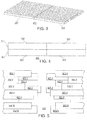
- FIG. 3 presents a representative view of a first layer 301 of collimating leaves for the multi-layer multi-leaf collimating system 205.
- this first layer 301 includes a plurality of selectively movable collimating leaves 302 that each comprise a first leaf for a corresponding pair of collimating leaves.
- This first layer 301 also includes a second plurality of selectively movable collimating leaves 303 that each comprise a second leaf for the aforementioned pair of collimating leaves. So configured, when one or both collimating leaves as comprise a pair of collimating leaves are selectively moved away from one another, a beam-shaping aperture forms therebetween. (The manner by which electric motors can be employed to effect such movement comprises a well understood area of prior art endeavor. Accordingly, for the sake of brevity, additional details in those regards are not provided here.)
- the second layer of collimating leaves for the multi-layer multi-leaf collimating system 205 can be identical to the first layer 301 described above. Or, if desired, these teachings will accommodate a variety of relatively small changes.
- the second layer of collimating leaves may include one or more additional pairs of collimating leaves or one or more fewer pairs of collimating leaves as compared to the first layer 301.
- the collimating leaves of the second layer may be somewhat greater in width or somewhat lesser in width than the collimating leaves of the first layer 301.
- the first layer 301 and second layer 401 of the collimating leaves are generally juxtaposed one atop the other (with or without some amount of intervening space as desired).
- the first layer 301 comprises a so-called proximal layer and hence is oriented towards the aforementioned radiation source 203.
- the second layer 401 comprises a so-called distal layer that is oriented opposite the radiation source 203 and towards the patient 207.
- the collimating leaves of the first layer 301 are generally laterally aligned with the collimating leaves of the second layer 401.
- the left side (as illustrated) collimating leaves 302 for the first layer 301 are laterally aligned with the left side collimating leaves 402 of the second layer 401.
- the right side (as illustrated) collimating leaves 303 of the first layer 301 are laterally aligned with the right side collimating leaves 403 of the second layer 401.
- the collimating leaves for these two layers 301 and 401 may be laterally aligned, as shown in FIG. 5 the collimation leaves for these two layers 301 and 401 are vertically offset with respect to one another.
- the word “vertically” as used herein refers to the orientation context shown in these illustrations. In an application setting the multi-layer multi-leaf collimation system 205 can be oriented in any of a variety of ways. Accordingly, it will be further understood that the word “vertically” as used herein refers to the relative context of the collimation leaves when the multi-layer multi-leaf collimation system 205 itself is oriented vertically and upright which will not necessarily correlate to the orientation of the system in a particular application setting.
- the left-side collimating leaves 302.1 - 302.N (where "N" is an integer) of the first layer 301 each only partially overlap the left-side collimating leaves 402.1-402.N of the second layer 401.
- the right-side collimating leaves 303.1-303.N of the first layer 301 each only partially overlap the right-side collimating leaves 403.1-403.N of the second layer 401.
- the collimating leaves of each layer are offset vertically by fifty percent and accordingly the first layer 301 has collimating leaves that each overlap corresponding leaves of the second layer 401 by fifty percent as well.
- the various leaves are depicted with the leaves of each leaf pair having been opened to some greater or lesser extent to facilitate better viewing of the collimating leaves of the second layer 401.
- FIGS. 6 - 8 provide an illustrative example in these regards.
- FIG. 6 depicts an aperture 601 formed using collimating leaves of the first layer 301.
- a pair of collimating leaves 302.2 and 303.2 have been moved away from one another while the collimating leaves above and below that pair of collimating leaves remain closed to form that aperture 601.
- this aperture 601 has a vertical dimension identical to the vertical dimensions of that pair of collimating leaves.
- FIG. 7 presents an aperture 701 formed in an identical manner to that just described, albeit using collimating leaves of the second layer 401. Again, the resultant aperture 701 has a vertical dimension that is necessarily identical to the vertical dimensions of the collimating leaves.
- FIG. 8 illustrates the aperture 801 that results when the two layers 301 and 401 are stacked one atop the other in a vertically offset manner as described above. Accordingly, the two apertures 601 and 701 described above only partially overlap one another to form this resultant aperture 801.
- the aperture 801 has a vertical dimension that is only one half the vertical dimension of the collimating leaves. Accordingly, this particular approach yields a 2X improvement in aperture resolution in these regards. That improvement in resolution provides an opportunity to more precisely shape a radiation beam 204 to match the contours of a given treatment target.
- such an aperture 801 is referred to herein as a high-resolution aperture as such an aperture has higher resolution than apertures that can normally be formed by leaf pairs of either layer 301 or 401 alone. And, as is also illustrated in FIG. 8 , such a configuration gives rise to a plurality of linearly-sequential high-resolution aperture possibilities (numbered here as 802.1 through 802.7), it being understood that there are approximately twice as many linearly-sequential high-resolution aperture possibilities as there are leaf pairs in either layer 301 or 401.
- At least most of these high-resolution apertures will have at least one boundary (typically a horizontal boundary when presuming the orientation of convenience shown in the drawings) that is defined only by the proximal layer 301 and at least one other boundary (typically opposite the aforementioned boundary) that is defined by only the distal layer 401.
- at least one boundary typically a horizontal boundary when presuming the orientation of convenience shown in the drawings
- at least one other boundary typically opposite the aforementioned boundary
- this process 100 can be used in conjunction with a radiation therapy treatment platform 200 as described above having a multi-layer multi-leave collimation system 205 wherein a proximal layer 301 of a plurality of collimation leaf pairs 302 and 303 are vertically offset with respect to a distal layer 401 of a plurality of collimation leaf pairs 402 and 403 to form a plurality of linearly-sequential high-resolution aperture possibilities.
- this process 100 provides for having the control circuit 201 administer a radiation treatment plan that specifies a planned total radiation dose for a radiation treatment session for a given patient 207 by modulating a radiation beam 204 with at least one high-resolution aperture that is formed using one of the plurality of linearly-sequential high-resolution aperture possibilities.
- the high-resolution apertures are formed using overlapping low-resolution apertures, it will not necessarily be possible to form a high-resolution aperture for each and every available high-resolution aperture possibility. Instead, and as will be described in more detail below, it will sometimes be appropriate or even necessary to space one or more high-resolution apertures apart from one another with intervening unused high-resolution aperture possibilities. As a result, these teachings will accommodate using two or more separate radiation exposures for only a single treatment field in order to permit each of the separate radiation exposures for the single treatment field to comprise modulating the radiation beam using only (or at least substantially only) high-resolution apertures.
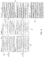
- FIG. 9 provides one illustrative example in these regards.
- a first set 901 of high-resolution apertures are employed during a first exposure of radiation for a particular treatment field followed by a second set 902 of high-resolution apertures that are employed during a second exposure of radiation for that same treatment field.
- the high-resolution apertures are grouped in sequential pairs with each such pair of high-resolution apertures being separated from any next-adjacent pairs of high-resolution apertures by a pair of sequential unused high-resolution aperture possibilities.
- each and every high-resolution aperture possibility features a corresponding high-resolution aperture. Accordingly, by using, in this case, only high-resolution apertures the radiation beam can be more precisely modulated and the radiation dose accordingly more carefully administered.
- FIG. 9 also illustrates the low-resolution apertures that are formed using the proximal layer 301 and the distal layer 401 of the multi-layer multi-leaf collimation system 205 which, when combined one with the other in an offset manner as described above, yields the corresponding high-resolution apertures shown at the right in the drawing.
- a low-resolution aperture is formed using only every other leaf pair in the proximal layer 301 for both exposures.
- the counter-cross-hatched areas in the two sets 901 and 902 of the high-resolution apertures represent an area where a low-resolution aperture formed in one layer does not coincide with a low-resolution aperture formed in the other layer.
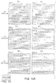
- FIG. 10 provides another illustrative example in these regards.
- a first set 1001 of high-resolution apertures are employed during a first exposure of radiation for a particular treatment field followed by a second set 1002 and then a third set 1003 of high-resolution apertures that are employed during a second and third exposure of radiation for that same treatment field.
- the high-resolution apertures are each separated from any next-adjacent high-resolution apertures by a sequential pair of unused high-resolution aperture possibilities.
- FIG. 10 also again illustrates the low-resolution apertures that are formed using the proximal layer 301 and the distal layer 401 of the multi-layer multi-leaf collimation system 205 which, when combined one with the other in an offset manner as described above, yields the corresponding high-resolution apertures shown at the right in the drawing.
- the counter-cross-hatched areas in the three sets 1001, 1002, and 1003 of the high-resolution apertures also again represent an area where a low-resolution aperture formed in one layer does not coincide with a low-resolution aperture formed in the other layer.
- a multi-layer multi-leaf collimation system can be successfully employed in a way that permits using only low-resolution apertures to nevertheless ultimately form in combination with one another only (or substantially only) high-resolution apertures to thereby help assure a more precise and accurate dosing of a patient's treatment target.
- the method comprising: by a control circuit: administering a radiation treatment plan that specifies a planned total radiation dose for a radiation treatment session for a given patient by modulating a radiation beam with at least one high-resolution aperture that is formed using one of the plurality of linearly-sequential high-resolution aperture possibilities.
- At least some of the plurality of linearly-sequential high-resolution aperture possibilities may have a height resolution that is twice the resolution of aperture possibilities that are available with either of the proximal or distal layer of the plurality of collimation leaf pairs alone.
- at least substantially all of the plurality of linearly-sequential high-resolution aperture possibilities may have a height resolution that is twice the resolution of aperture possibilities that are available with either of the proximal or distal layer of the plurality of collimation leaf pairs alone.
- the at least one high-resolution aperture may have at least one boundary defined only by the proximal layer and at least one other boundary defined only by the distal layer.
- administering the radiation treatment plan by modulating the radiation beam with at least one high-resolution aperture that is formed using one of the plurality of linearly-sequential high-resolution aperture possibilities may comprise administering the radiation treatment plan by modulating the radiation beam using at least substantially only high-resolution apertures that are formed using a plurality of the linearly-sequential high-resolution aperture possibilities.
- administering the radiation treatment plan may comprise using at least two separate radiation exposures for only a single treatment field, and wherein each of the separate radiation exposures for the single treatment field comprises modulating the radiation beam using at least substantially only high-resolution apertures.
- administering the radiation treatment plan may comprise using only two of the at least two separate exposures for only the single treatment field.
- the high-resolution apertures may be grouped in sequential pairs and the sequential pairs of high-resolution apertures may be separated from one another by a pair of sequential unused high-resolution aperture possibilities.
- administering the radiation treatment plan may comprise using only three of the at least two separate exposures for only the single treatment field.
- the high-resolution apertures may each be separated from a next sequential high-resolution aperture by a pair of sequential unused high-resolution aperture possibilities.
- an apparatus comprising: a source of therapeutic radiation configured to emit a radiation beam; a multi-layer multi-leaf collimation system wherein a proximal layer of a plurality of collimation leaf pairs are vertically offset with respect to a distal layer of a plurality of collimation leaf pairs such that the two multi-layer multi-leaf collimators combine to form a plurality of linearly-sequential high-resolution aperture possibilities; and a control circuit operably coupled to the source of therapeutic radiation and to the multi-layer multi-leave collimation system, the control circuit being configured to administer a radiation treatment plan that specifies a planned total radiation dose for a radiation treatment session for a given patient by modulating the radiation beam with at least one high-resolution aperture that is formed using one of the plurality of linearly-sequential high-resolution aperture possibilities.
- At least some of the plurality of linearly-sequential high-resolution aperture possibilities may have a height resolution that is twice the resolution of aperture possibilities that are available with either of the proximal or distal layer of the plurality of collimation leaf pairs alone.
- at least substantially all of the plurality of linearly-sequential high-resolution aperture possibilities may have a height resolution that is twice the resolution of aperture possibilities that are available with either of the proximal or distal layer of the plurality of collimation leaf pairs alone.
- the at least one high-resolution aperture may have at least one boundary defined only by the proximal layer and at least one other boundary defined only by the distal layer.
- control circuit may be configured to administer the radiation treatment plan by modulating the radiation beam using at least substantially only high-resolution apertures that are formed using a plurality of the linearly-sequential high-resolution aperture possibilities. Further, in the apparatus, the control circuit may be configured to administer the radiation treatment plan by using at least two separate radiation exposures for only a single treatment field, wherein each of the separate radiation exposures for the single treatment field comprises modulating the radiation beam using at least substantially only high-resolution apertures. Moreover, in the apparatus, the control circuit may be configured to administer the radiation treatment plan by using only two of the at least two separate exposures for only the single treatment field.
- the high-resolution apertures may be grouped in sequential pairs and the sequential pairs of high-resolution apertures may be separated from one another by a pair of sequential unused high-resolution aperture possibilities.
- the control circuit may be configured to administer the radiation treatment plan using only three of the at least two separate exposures for only the single treatment field.
- the high-resolution apertures may each be separated from a next sequential high-resolution aperture by a pair of sequential unused high-resolution aperture possibilities.
Landscapes
- Health & Medical Sciences (AREA)
- Engineering & Computer Science (AREA)
- Biomedical Technology (AREA)
- Pathology (AREA)
- Nuclear Medicine, Radiotherapy & Molecular Imaging (AREA)
- Radiology & Medical Imaging (AREA)
- Life Sciences & Earth Sciences (AREA)
- Animal Behavior & Ethology (AREA)
- General Health & Medical Sciences (AREA)
- Public Health (AREA)
- Veterinary Medicine (AREA)
- Physics & Mathematics (AREA)
- Spectroscopy & Molecular Physics (AREA)
- General Engineering & Computer Science (AREA)
- High Energy & Nuclear Physics (AREA)
- Radiation-Therapy Devices (AREA)
Abstract
Description
- These teachings relate generally to the administration of therapeutic doses of radiation and more particularly to the use of multi-leaf collimators.
- Multi-leaf collimators are comprised of a plurality of individual parts (known as "leaves") that are formed of a high atomic numbered material (such as tungsten) that can move independently in and out of the path of the radiation-therapy beam in order to selectively block (and hence shape) the beam. Typically the leaves of a multi-leaf collimator are organized in pairs that are aligned collinearly with respect to one another and that can selectively move towards and away from one another via controlled motors. A typical multi-leaf collimator has many such pairs of leaves, often upwards of twenty, fifty, or even one hundred such pairs.
- By passing a therapeutic radiation beam through the aperture(s) of a multi-leaf collimator the radiation beam can be modulated to better match the dosing requirements of the treatment session. These dosing requirements typically include (or at least presume) prescribing which body tissues to irradiate and which body tissues to avoid irradiating.
- While a typical multi-leaf collimator represents an enormous improvement in terms of better shaping a radiation beam to meet such requirements, it nevertheless remains true that, at least some of the time, the resultant beam shape does not perfectly meet such requirements. This shortcoming typically arises as a function of the maximum resolution by which the multi-leaf collimator is able to shape the beam. When the leaves of the multi-leaf collimator have a cross-dimension of, for example, 1.0 centimeter, that is generally orthogonal to the incoming beam, that dimension imposes a corresponding limit as to the resolution capabilities of the collimator.
- According to a first aspect of the present invention, there is provided a method for use with a radiation therapy treatment platform having a multi-layer multi-leaf collimation system wherein a proximal layer of a plurality of collimation leaf pairs are vertically offset with respect to a distal layer of a plurality of collimation leaf pairs such that the two multi-layer multi-leaf collimators combine to form a plurality of linearly-sequential high-resolution aperture possibilities, the method comprising:
- by a control circuit:
- administering a radiation treatment plan that specifies a planned total radiation dose for a radiation treatment session for a given patient by modulating a radiation beam with at least one high-resolution aperture that is formed using one of the plurality of linearly-sequential high-resolution aperture possibilities.
- According to a second aspect of the present invention, there is provided an apparatus comprising:
- a source of therapeutic radiation configured to emit a radiation beam;
- a multi-layer multi-leaf collimation system wherein a proximal layer of a plurality of collimation leaf pairs are vertically offset with respect to a distal layer of a plurality of collimation leaf pairs such that the two multi-layer multi-leaf collimators combine to form a plurality of linearly-sequential high-resolution aperture possibilities; and
- a control circuit operably coupled to the source of therapeutic radiation and to the multi-layer multi-leave collimation system, the control circuit being configured to administer a radiation treatment plan that specifies a planned total radiation dose for a radiation treatment session for a given patient by modulating a radiation beam with at least one high-resolution aperture that is formed using one of the plurality of linearly-sequential high-resolution aperture possibilities.
- Optional features of the invention are specified in the dependent claims.
- The above needs are at least partially met through provision of the method and apparatus to employ a multi-layer multi-leaf collimator when administering a radiation therapy treatment described in the following detailed description, particularly when studied in conjunction with the drawings, wherein:
-
FIG. 1 comprises a flow diagram as configured in accordance with various embodiments of these teachings; -
FIG. 2 comprises a block diagram as configured in accordance with various embodiments of these teachings; -
FIG. 3 comprises a perspective schematic view as configured in accordance with various embodiments of these teachings; -
FIG. 4 comprises a front elevational schematic view as configured in accordance with various embodiments of these teachings; -
FIG. 5 comprises a top plan view as configured in accordance with various embodiments of these teachings; -
FIG. 6 comprises a top plan view as configured in accordance with various embodiments of these teachings; -
FIG. 7 comprises a top plan view as configured in accordance with various embodiments of the invention; -
FIG. 8 comprises a top plan view as configured in accordance with various embodiments of these teachings; -
FIG. 9 comprises front-elevational views as configured in accordance with various embodiments of these teachings; and -
FIG. 10 (FIGS. 10A and10B ) comprises front-elevational views as configured in accordance with various embodiments of these teachings. - Elements in the figures are illustrated for simplicity and clarity and have not necessarily been drawn to scale. For example, the dimensions and/or relative positioning of some of the elements in the figures may be exaggerated relative to other elements to help to improve understanding of various embodiments of the present teachings. Also, common but well-understood elements that are useful or necessary in a commercially feasible embodiment are often not depicted in order to facilitate a less obstructed view of these various embodiments of the present teachings. Certain actions and/or steps may be described or depicted in a particular order of occurrence while those skilled in the art will understand that such specificity with respect to sequence is not actually required. The terms and expressions used herein have the ordinary technical meaning as is accorded to such terms and expressions by persons skilled in the technical field as set forth above except where different specific meanings have otherwise been set forth herein.
- Generally speaking, pursuant to these various embodiments, a control circuit administers a radiation treatment plan that specifies a planned total radiation dose for a radiation treatment session for a given patient by modulating a radiation beam with at least one high-resolution aperture that is formed using one of a plurality of linearly-sequential high-resolution aperture possibilities. By one approach the foregoing comprises modulating the radiation beam using at least substantially only high-resolution apertures that are formed using a plurality of the linearly-sequential high-resolution aperture possibilities. In some cases the foregoing can comprise administering the radiation treatment plan using at least two separate radiation exposures for only a single treatment field, in which case, by one approach, each of the separate radiation exposures for the single treatment field can comprise modulating the radiation beam using at least substantially only high-resolution apertures.
- By one approach at least some of the plurality of linearly-sequential high-resolution aperture possibilities have a height resolution that is twice the resolution of aperture possibilities that are available with either a proximal or distal layer of a plurality of collimation leaf pairs alone. For many application settings it will be useful that at least substantially all of the plurality of linearly-sequential high-resolution aperture possibilities have a height resolution that is twice the resolution of aperture possibilities that are available with either of the proximal or distal layer of the plurality of collimation leaf pairs alone. In many cases such a high-resolution aperture has at least one boundary defined only by the proximal layer and at least one other boundary defined only by the distal layer.
- These teachings are highly flexible in practice and will accommodate a variety of approaches in the foregoing regards. By one approach, for example, administering the radiation treatment plan comprises using two (and only two) separate exposures for a single treatment field and where the high-resolution apertures are grouped in sequential pairs and the sequential pairs of high-resolution apertures are separated from one another by a pair of sequential unused high-resolution aperture possibilities.
- By another approach, and as another example in these regards, administering the radiation treatment plan comprises using three (and only three) separate exposures for a single treatment field and where the high-resolution apertures are each separated from a next sequential high-resolution aperture by a pair of sequential unused high-resolution aperture possibilities.
- So configured, these approaches help address the deficiencies of prior art techniques that do not work well with two or more layers of multi-leaf collimators. In particular, the present teachings can greatly aid in leveraging such additional layers to improve the definition and/or resolution of beam-shaping apertures. Such improvements, in turn, can further help to assure that treatment targets receive a desired radiation dosage while non-targeted surrounding areas receive less unwanted radiation.
- These and other benefits may become clearer upon making a thorough review and study of the following detailed description. Referring now to the drawings, and in particular to
FIG. 1 , anillustrative process 100 that is compatible with many of these teachings will now be presented. For the sake of an illustrative example it is presumed here in that a control circuit of choice carries out the steps, actions, and/or functionality of thisprocess 100.FIG. 2 presents an illustrative example in this regard. - As shown in
FIG. 2 , a radiationtherapy treatment platform 200 can include or otherwise operably couple to acontrol circuit 201. Being a "circuit," thecontrol circuit 201 therefore comprises structure that includes at least one (and typically many) electrically-conductive paths (such as paths comprised of a conductive metal such as copper or silver) that convey electricity in an ordered manner, which path(s) will also typically include corresponding electrical components (both passive (such as resistors and capacitors) and active (such as any of a variety of semiconductor-based devices) as appropriate) to permit the circuit to effect the control aspect of these teachings. - Such a
control circuit 201 can comprise a fixed-purpose hard-wired hardware platform (including but not limited to an application-specific integrated circuit (ASIC) (which is an integrated circuit that is customized by design for a particular use, rather than intended for general-purpose use), a field-programmable gate array (FPGA), and the like) or can comprise a partially or wholly-programmable hardware platform (including but not limited to microcontrollers, microprocessors, and the like). These architectural options for such structures are well known and understood in the art and require no further description here. Thiscontrol circuit 201 is configured (for example, by using corresponding programming as will be well understood by those skilled in the art) to carry out one or more of the steps, actions, and/or functions described herein. It will also be understood that a "control circuit" can comprise multiple such components or platforms as well as suggested by the phantom control circuit box inFIG. 2 . - By one optional approach the
control circuit 201 operably couples to amemory 202. Thismemory 202 may be integral to thecontrol circuit 201 or can be physically discrete (in whole or in part) from thecontrol circuit 201 as desired. Thismemory 202 can also be local with respect to the control circuit 201 (where, for example, both share a common circuit board, chassis, power supply, and/or housing) or can be partially or wholly remote with respect to the control circuit 201 (where, for example, thememory 202 is physically located in another facility, metropolitan area, or even country as compared to the control circuit 201). - In addition to radiation treatment plans this
memory 202 can serve, for example, to non-transitorily store the computer instructions that, when executed by thecontrol circuit 201, cause thecontrol circuit 201 to behave as described herein. (As used herein, this reference to "non-transitorily" will be understood to refer to a non-ephemeral state for the stored contents (and hence excludes when the stored contents merely constitute signals or waves) rather than volatility of the storage media itself and hence includes both non-volatile memory (such as read-only memory (ROM) as well as volatile memory (such as an erasable programmable read-only memory (EPROM).) - The radiation
therapy treatment platform 200 also includes aradiation source 203 that operably couples and responds to thecontrol circuit 201. So configured, the correspondingradiation beam 204 as emitted by theradiation source 203 can be selectively switched on and off by thecontrol circuit 201. These teachings will also accommodate having thecontrol circuit 201 control the relative strength of theradiation beam 204. Radiation sources are well understood in the art and require no further description here. - The
radiation beam 204 is directed towards a multi-layermulti-leaf collimation system 205 that also operably couples to thecontrol circuit 201 to thereby permit thecontrol circuit 201 to control movement of the collimation systems leaves and hence the formation and distribution of one or more radiation-modulating apertures. The resultant modulatedradiation beam 206 then reaches a treatment target in acorresponding patient 207. -
FIG. 3 presents a representative view of afirst layer 301 of collimating leaves for the multi-layermulti-leaf collimating system 205. Generally speaking thisfirst layer 301 includes a plurality of selectively movable collimating leaves 302 that each comprise a first leaf for a corresponding pair of collimating leaves. Thisfirst layer 301 also includes a second plurality of selectively movable collimating leaves 303 that each comprise a second leaf for the aforementioned pair of collimating leaves. So configured, when one or both collimating leaves as comprise a pair of collimating leaves are selectively moved away from one another, a beam-shaping aperture forms therebetween. (The manner by which electric motors can be employed to effect such movement comprises a well understood area of prior art endeavor. Accordingly, for the sake of brevity, additional details in those regards are not provided here.) - The second layer of collimating leaves for the multi-layer
multi-leaf collimating system 205 can be identical to thefirst layer 301 described above. Or, if desired, these teachings will accommodate a variety of relatively small changes. For example, the second layer of collimating leaves may include one or more additional pairs of collimating leaves or one or more fewer pairs of collimating leaves as compared to thefirst layer 301. As another example, the collimating leaves of the second layer may be somewhat greater in width or somewhat lesser in width than the collimating leaves of thefirst layer 301. - In any event, and as generally represented in
FIG. 4 , thefirst layer 301 andsecond layer 401 of the collimating leaves are generally juxtaposed one atop the other (with or without some amount of intervening space as desired). In this example thefirst layer 301 comprises a so-called proximal layer and hence is oriented towards theaforementioned radiation source 203. Accordingly, thesecond layer 401 comprises a so-called distal layer that is oriented opposite theradiation source 203 and towards thepatient 207. - In this illustrative example the collimating leaves of the
first layer 301 are generally laterally aligned with the collimating leaves of thesecond layer 401. For example, the left side (as illustrated) collimating leaves 302 for thefirst layer 301 are laterally aligned with the left side collimating leaves 402 of thesecond layer 401. Similarly, the right side (as illustrated) collimating leaves 303 of thefirst layer 301 are laterally aligned with the right side collimating leaves 403 of thesecond layer 401. These teachings are highly flexible in practice and will accommodate other orientations and juxtapositions as may be useful to address the needs of a specific application setting. For example, it may be useful in some cases to laterally offset the collimating leaves of one layer from the collimating leaves of the other layer. - Although the collimating leaves for these two
layers FIG. 5 the collimation leaves for these twolayers multi-leaf collimation system 205 can be oriented in any of a variety of ways. Accordingly, it will be further understood that the word "vertically" as used herein refers to the relative context of the collimation leaves when the multi-layermulti-leaf collimation system 205 itself is oriented vertically and upright which will not necessarily correlate to the orientation of the system in a particular application setting.) - Accordingly, it can be seen that the left-side collimating leaves 302.1 - 302.N (where "N" is an integer) of the
first layer 301 each only partially overlap the left-side collimating leaves 402.1-402.N of thesecond layer 401. Similarly, the right-side collimating leaves 303.1-303.N of thefirst layer 301 each only partially overlap the right-side collimating leaves 403.1-403.N of thesecond layer 401. In the illustrated example the collimating leaves of each layer are offset vertically by fifty percent and accordingly thefirst layer 301 has collimating leaves that each overlap corresponding leaves of thesecond layer 401 by fifty percent as well. In this example the various leaves are depicted with the leaves of each leaf pair having been opened to some greater or lesser extent to facilitate better viewing of the collimating leaves of thesecond layer 401. - The applicant has determined that the aperture resolution capable of a multi-leaf collimator can be significantly increased by employing such a multi-layer
multi-leaf collimator 205.FIGS. 6 - 8 provide an illustrative example in these regards.FIG. 6 depicts anaperture 601 formed using collimating leaves of thefirst layer 301. In this simple example, a pair of collimating leaves 302.2 and 303.2 have been moved away from one another while the collimating leaves above and below that pair of collimating leaves remain closed to form thataperture 601. Necessarily, thisaperture 601 has a vertical dimension identical to the vertical dimensions of that pair of collimating leaves. -
FIG. 7 presents anaperture 701 formed in an identical manner to that just described, albeit using collimating leaves of thesecond layer 401. Again, theresultant aperture 701 has a vertical dimension that is necessarily identical to the vertical dimensions of the collimating leaves. -
FIG. 8 illustrates theaperture 801 that results when the twolayers apertures resultant aperture 801. In this particular illustrative example theaperture 801 has a vertical dimension that is only one half the vertical dimension of the collimating leaves. Accordingly, this particular approach yields a 2X improvement in aperture resolution in these regards. That improvement in resolution provides an opportunity to more precisely shape aradiation beam 204 to match the contours of a given treatment target. - Accordingly, such an
aperture 801 is referred to herein as a high-resolution aperture as such an aperture has higher resolution than apertures that can normally be formed by leaf pairs of eitherlayer FIG. 8 , such a configuration gives rise to a plurality of linearly-sequential high-resolution aperture possibilities (numbered here as 802.1 through 802.7), it being understood that there are approximately twice as many linearly-sequential high-resolution aperture possibilities as there are leaf pairs in eitherlayer - The word "possibility" serves to indicate that a high-resolution aperture can be formed in the space indicated if desired through ordinary and usual manipulation of the aforementioned leaf pairs. In the illustration of
FIG. 8 , while there are seven such linearly-sequential high-resolution aperture possibilities, only one possibility (the one denoted by reference numeral 802.4) actually features a realized high-resolution aperture 801. - Generally speaking, at least most of these high-resolution apertures will have at least one boundary (typically a horizontal boundary when presuming the orientation of convenience shown in the drawings) that is defined only by the
proximal layer 301 and at least one other boundary (typically opposite the aforementioned boundary) that is defined by only thedistal layer 401. - In many application settings it will be useful if at least some of the plurality of linearly-sequential high-resolution aperture possibilities have a height resolution that is twice the resolution of aperture possibilities that are available with either of the proximal or distal layer of the plurality of leaf pairs alone, and in many cases it will be useful if at least substantially all of those possibilities have such a height resolution. (As used herein, this reference to "substantially all" shall be understood to mean at least ninety percent of all such possibilities.)
- With continued reference to the foregoing illustrations, and in particular to
FIG. 1 and 2 , thisprocess 100 can be used in conjunction with a radiationtherapy treatment platform 200 as described above having a multi-layermulti-leave collimation system 205 wherein aproximal layer 301 of a plurality of collimation leaf pairs 302 and 303 are vertically offset with respect to adistal layer 401 of a plurality of collimation leaf pairs 402 and 403 to form a plurality of linearly-sequential high-resolution aperture possibilities. Atblock 101 thisprocess 100 provides for having thecontrol circuit 201 administer a radiation treatment plan that specifies a planned total radiation dose for a radiation treatment session for a givenpatient 207 by modulating aradiation beam 204 with at least one high-resolution aperture that is formed using one of the plurality of linearly-sequential high-resolution aperture possibilities. - Because the high-resolution apertures are formed using overlapping low-resolution apertures, it will not necessarily be possible to form a high-resolution aperture for each and every available high-resolution aperture possibility. Instead, and as will be described in more detail below, it will sometimes be appropriate or even necessary to space one or more high-resolution apertures apart from one another with intervening unused high-resolution aperture possibilities. As a result, these teachings will accommodate using two or more separate radiation exposures for only a single treatment field in order to permit each of the separate radiation exposures for the single treatment field to comprise modulating the radiation beam using only (or at least substantially only) high-resolution apertures.
-
FIG. 9 provides one illustrative example in these regards. In this example afirst set 901 of high-resolution apertures are employed during a first exposure of radiation for a particular treatment field followed by asecond set 902 of high-resolution apertures that are employed during a second exposure of radiation for that same treatment field. In both thefirst set 901 and thesecond set 902 the high-resolution apertures are grouped in sequential pairs with each such pair of high-resolution apertures being separated from any next-adjacent pairs of high-resolution apertures by a pair of sequential unused high-resolution aperture possibilities. - The net aggregated effect of this two-exposure approach that employs such a grouping and spacing is illustrated at
reference numeral 903 where, in this example, each and every high-resolution aperture possibility features a corresponding high-resolution aperture. Accordingly, by using, in this case, only high-resolution apertures the radiation beam can be more precisely modulated and the radiation dose accordingly more carefully administered. -
FIG. 9 also illustrates the low-resolution apertures that are formed using theproximal layer 301 and thedistal layer 401 of the multi-layermulti-leaf collimation system 205 which, when combined one with the other in an offset manner as described above, yields the corresponding high-resolution apertures shown at the right in the drawing. In this particular example a low-resolution aperture is formed using only every other leaf pair in theproximal layer 301 for both exposures. (The counter-cross-hatched areas in the twosets -
FIG. 10 provides another illustrative example in these regards. In this example afirst set 1001 of high-resolution apertures are employed during a first exposure of radiation for a particular treatment field followed by asecond set 1002 and then athird set 1003 of high-resolution apertures that are employed during a second and third exposure of radiation for that same treatment field. In all threesets - The net effect of this three-exposure approach that employs such a grouping and spacing is illustrated at
reference numeral 1004 where, in this example, each and every high-resolution aperture possibility again features a corresponding high-resolution aperture. It may be noted that the result shown atreference numeral 1004 is essentially the same as that depicted atreference numeral 903 inFIG. 9 discussed above. Accordingly, these two examples constitute two different multi-exposure approaches to achieving a same net, aggregate pattern of high-resolution apertures. -
FIG. 10 also again illustrates the low-resolution apertures that are formed using theproximal layer 301 and thedistal layer 401 of the multi-layermulti-leaf collimation system 205 which, when combined one with the other in an offset manner as described above, yields the corresponding high-resolution apertures shown at the right in the drawing. The counter-cross-hatched areas in the threesets - So configured, a multi-layer multi-leaf collimation system can be successfully employed in a way that permits using only low-resolution apertures to nevertheless ultimately form in combination with one another only (or substantially only) high-resolution apertures to thereby help assure a more precise and accurate dosing of a patient's treatment target.
- Certain forms of the methods and apparatuses described herein are summarized as follows. In one form, there is provided herein a method for use with a radiation therapy treatment platform having a multi-layer multi-leaf collimation system wherein a proximal layer of a plurality of collimation leaf pairs are vertically offset with respect to a distal layer of a plurality of collimation leaf pairs such that the two multi-layer multi-leaf collimators combine to form a plurality of linearly-sequential high-resolution aperture possibilities, the method comprising: by a control circuit: administering a radiation treatment plan that specifies a planned total radiation dose for a radiation treatment session for a given patient by modulating a radiation beam with at least one high-resolution aperture that is formed using one of the plurality of linearly-sequential high-resolution aperture possibilities.
- Further, in the method, at least some of the plurality of linearly-sequential high-resolution aperture possibilities may have a height resolution that is twice the resolution of aperture possibilities that are available with either of the proximal or distal layer of the plurality of collimation leaf pairs alone. In addition, in the method, at least substantially all of the plurality of linearly-sequential high-resolution aperture possibilities may have a height resolution that is twice the resolution of aperture possibilities that are available with either of the proximal or distal layer of the plurality of collimation leaf pairs alone. Also, in the method, the at least one high-resolution aperture may have at least one boundary defined only by the proximal layer and at least one other boundary defined only by the distal layer.
- Moreover, in the method, administering the radiation treatment plan by modulating the radiation beam with at least one high-resolution aperture that is formed using one of the plurality of linearly-sequential high-resolution aperture possibilities may comprise administering the radiation treatment plan by modulating the radiation beam using at least substantially only high-resolution apertures that are formed using a plurality of the linearly-sequential high-resolution aperture possibilities. Further, administering the radiation treatment plan may comprise using at least two separate radiation exposures for only a single treatment field, and wherein each of the separate radiation exposures for the single treatment field comprises modulating the radiation beam using at least substantially only high-resolution apertures. In addition, administering the radiation treatment plan may comprise using only two of the at least two separate exposures for only the single treatment field.
- Also, in the method, the high-resolution apertures may be grouped in sequential pairs and the sequential pairs of high-resolution apertures may be separated from one another by a pair of sequential unused high-resolution aperture possibilities. Moreover, in the method, administering the radiation treatment plan may comprise using only three of the at least two separate exposures for only the single treatment field. In addition, in the method, the high-resolution apertures may each be separated from a next sequential high-resolution aperture by a pair of sequential unused high-resolution aperture possibilities.
- In another form, there is provided herein an apparatus comprising: a source of therapeutic radiation configured to emit a radiation beam; a multi-layer multi-leaf collimation system wherein a proximal layer of a plurality of collimation leaf pairs are vertically offset with respect to a distal layer of a plurality of collimation leaf pairs such that the two multi-layer multi-leaf collimators combine to form a plurality of linearly-sequential high-resolution aperture possibilities; and a control circuit operably coupled to the source of therapeutic radiation and to the multi-layer multi-leave collimation system, the control circuit being configured to administer a radiation treatment plan that specifies a planned total radiation dose for a radiation treatment session for a given patient by modulating the radiation beam with at least one high-resolution aperture that is formed using one of the plurality of linearly-sequential high-resolution aperture possibilities.
- Further, in the apparatus, at least some of the plurality of linearly-sequential high-resolution aperture possibilities may have a height resolution that is twice the resolution of aperture possibilities that are available with either of the proximal or distal layer of the plurality of collimation leaf pairs alone. In addition, in the apparatus, at least substantially all of the plurality of linearly-sequential high-resolution aperture possibilities may have a height resolution that is twice the resolution of aperture possibilities that are available with either of the proximal or distal layer of the plurality of collimation leaf pairs alone. Moreover, in the apparatus, the at least one high-resolution aperture may have at least one boundary defined only by the proximal layer and at least one other boundary defined only by the distal layer.
- Also, in the apparatus, the control circuit may be configured to administer the radiation treatment plan by modulating the radiation beam using at least substantially only high-resolution apertures that are formed using a plurality of the linearly-sequential high-resolution aperture possibilities. Further, in the apparatus, the control circuit may be configured to administer the radiation treatment plan by using at least two separate radiation exposures for only a single treatment field, wherein each of the separate radiation exposures for the single treatment field comprises modulating the radiation beam using at least substantially only high-resolution apertures. Moreover, in the apparatus, the control circuit may be configured to administer the radiation treatment plan by using only two of the at least two separate exposures for only the single treatment field.
- In addition, in the apparatus, the high-resolution apertures may be grouped in sequential pairs and the sequential pairs of high-resolution apertures may be separated from one another by a pair of sequential unused high-resolution aperture possibilities. Further, in the apparatus, the control circuit may be configured to administer the radiation treatment plan using only three of the at least two separate exposures for only the single treatment field. Also, in the apparatus, the high-resolution apertures may each be separated from a next sequential high-resolution aperture by a pair of sequential unused high-resolution aperture possibilities.
- Those skilled in the art will recognize that a wide variety of modifications, alterations, and combinations can be made with respect to the above described embodiments without departing from the scope of the invention, and that such modifications, alterations, and combinations are to be viewed as being within the ambit of the inventive concept.
Claims (11)
- A method for use with a radiation therapy treatment platform having a multi-layer multi-leaf collimation system wherein a proximal layer of a plurality of collimation leaf pairs are vertically offset with respect to a distal layer of a plurality of collimation leaf pairs such that the two multi-layer multi-leaf collimators combine to form a plurality of linearly-sequential high-resolution aperture possibilities, the method comprising:by a control circuit:administering a radiation treatment plan that specifies a planned total radiation dose for a radiation treatment session for a given patient by modulating a radiation beam with at least one high-resolution aperture that is formed using one of the plurality of linearly-sequential high-resolution aperture possibilities.
- An apparatus comprising:a source of therapeutic radiation configured to emit a radiation beam;a multi-layer multi-leaf collimation system wherein a proximal layer of a plurality of collimation leaf pairs are vertically offset with respect to a distal layer of a plurality of collimation leaf pairs such that the two multi-layer multi-leaf collimators combine to form a plurality of linearly-sequential high-resolution aperture possibilities; anda control circuit operably coupled to the source of therapeutic radiation and to the multi-layer multi-leave collimation system, the control circuit being configured to carry out the method of claim 1.
- Either of claim 1 and 2 wherein at least some of the plurality of linearly-sequential high-resolution aperture possibilities have a height resolution that is twice the resolution of aperture possibilities that are available with either of the proximal or distal layer of the plurality of collimation leaf pairs alone.
- Claim 3 wherein at least substantially all of the plurality of linearly-sequential high-resolution aperture possibilities have a height resolution that is twice the resolution of aperture possibilities that are available with either of the proximal or distal layer of the plurality of collimation leaf pairs alone.
- Either of claim 1 and 2 wherein the at least one high-resolution aperture has at least one boundary defined only by the proximal layer and at least one other boundary defined only by the distal layer.
- Either of claim 1 and 2 wherein administering the radiation treatment plan by modulating the radiation beam with at least one high-resolution aperture that is formed using one of the plurality of linearly-sequential high-resolution aperture possibilities comprises administering the radiation treatment plan by modulating the radiation beam using at least substantially only high-resolution apertures that are formed using a plurality of the linearly-sequential high-resolution aperture possibilities.
- Claim 6 wherein administering the radiation treatment plan comprises using at least two separate radiation exposures for only a single treatment field, and wherein each of the separate radiation exposures for the single treatment field comprises modulating the radiation beam using at least substantially only high-resolution apertures.
- Claim 7 wherein administering the radiation treatment plan comprises using only two of the at least two separate exposures for only the single treatment field.
- Claim 8 wherein the high-resolution apertures are grouped in sequential pairs and the sequential pairs of high-resolution apertures are separated from one another by a pair of sequential unused high-resolution aperture possibilities.
- Claim 7 wherein administering the radiation treatment plan comprises using only three of the at least two separate exposures for only the single treatment field.
- Claim 10 wherein the high-resolution apertures are each separated from a next sequential high-resolution aperture by a pair of sequential unused high-resolution aperture possibilities.
Applications Claiming Priority (1)
| Application Number | Priority Date | Filing Date | Title |
|---|---|---|---|
| US14/865,890 US10441814B2 (en) | 2015-09-25 | 2015-09-25 | Method and apparatus to employ a multi-layer multi-leaf collimator when administering a radiation therapy treatment |
Publications (2)
| Publication Number | Publication Date |
|---|---|
| EP3146998A1 true EP3146998A1 (en) | 2017-03-29 |
| EP3146998B1 EP3146998B1 (en) | 2020-11-04 |
Family
ID=56853549
Family Applications (1)
| Application Number | Title | Priority Date | Filing Date |
|---|---|---|---|
| EP16187121.5A Active EP3146998B1 (en) | 2015-09-25 | 2016-09-02 | Apparatus to employ a multi-layer multi-leaf collimator when administering a radiation therapy treatment |
Country Status (3)
| Country | Link |
|---|---|
| US (1) | US10441814B2 (en) |
| EP (1) | EP3146998B1 (en) |
| CN (1) | CN106552324B (en) |
Cited By (2)
| Publication number | Priority date | Publication date | Assignee | Title |
|---|---|---|---|---|
| WO2019081233A1 (en) * | 2017-10-26 | 2019-05-02 | Varian Medical Systems International Ag | Method and apparatus for using a multi-layer multi-leaf collimation system |
| WO2020127659A1 (en) * | 2018-12-20 | 2020-06-25 | Raysearch Laboratories Ab | System and method for planning of passive ion radiotherapy treatment |
Families Citing this family (7)
| Publication number | Priority date | Publication date | Assignee | Title |
|---|---|---|---|---|
| CN209734772U (en) * | 2017-09-12 | 2019-12-06 | 余丽 | Multi-blade collimator |
| CN210131259U (en) * | 2017-09-20 | 2020-03-10 | 西安大医集团股份有限公司 | Multi-leaf collimator and radiotherapy head |
| CN108031015B (en) * | 2017-12-19 | 2020-12-08 | 连卫东 | A multi-layer multi-blade collimator |
| US11869680B2 (en) * | 2018-03-30 | 2024-01-09 | Varian Medical Systems International Ag | Treating a treatment volume with therapeutic radiation using a multi-leaf collimation system |
| CN111388881B (en) | 2020-03-23 | 2022-01-28 | 上海联影医疗科技股份有限公司 | Control method and system of beam limiting device |
| US11511130B2 (en) | 2020-04-15 | 2022-11-29 | Shanghai United Imaging Healthcare Co., Ltd. | Systems and methods for adjusting multi-leaf collimator |
| CN111681736B (en) * | 2020-06-08 | 2023-05-12 | 苏州雷泰医疗科技有限公司 | Orthogonal double-layer grating dynamic intensity modulation segmentation method based on quadrant division |
Citations (3)
| Publication number | Priority date | Publication date | Assignee | Title |
|---|---|---|---|---|
| US5748703A (en) * | 1994-03-22 | 1998-05-05 | Cosman; Eric R. | Dynamic collimator for a linear accelerator |
| US20010043669A1 (en) * | 1997-09-29 | 2001-11-22 | Moshe Ein-Gal | Multiple layer multileaf collimator |
| US6600810B1 (en) * | 1998-08-10 | 2003-07-29 | Siemens Medical Solutions Usa, Inc. | Multiple layer multileaf collimator design to improve resolution and reduce leakage |
Family Cites Families (4)
| Publication number | Priority date | Publication date | Assignee | Title |
|---|---|---|---|---|
| US6687330B2 (en) * | 2001-07-31 | 2004-02-03 | Siemens Medical Solutions Usa, Inc. | System and method for intensity modulated radiation therapy |
| JP2004275636A (en) * | 2003-03-19 | 2004-10-07 | Nakano Syst:Kk | Radiation treatment planning device |
| CN102421860B (en) * | 2009-03-12 | 2014-05-14 | 巴斯夫欧洲公司 | Solid pigment preparations containing phosphates or phosphonates as surface-active additives |
| US8637841B2 (en) | 2010-08-23 | 2014-01-28 | Varian Medical Systems, Inc. | Multi level multileaf collimators |
-
2015
- 2015-09-25 US US14/865,890 patent/US10441814B2/en active Active
-
2016
- 2016-09-02 EP EP16187121.5A patent/EP3146998B1/en active Active
- 2016-09-23 CN CN201610848795.0A patent/CN106552324B/en active Active
Patent Citations (3)
| Publication number | Priority date | Publication date | Assignee | Title |
|---|---|---|---|---|
| US5748703A (en) * | 1994-03-22 | 1998-05-05 | Cosman; Eric R. | Dynamic collimator for a linear accelerator |
| US20010043669A1 (en) * | 1997-09-29 | 2001-11-22 | Moshe Ein-Gal | Multiple layer multileaf collimator |
| US6600810B1 (en) * | 1998-08-10 | 2003-07-29 | Siemens Medical Solutions Usa, Inc. | Multiple layer multileaf collimator design to improve resolution and reduce leakage |
Cited By (4)
| Publication number | Priority date | Publication date | Assignee | Title |
|---|---|---|---|---|
| WO2019081233A1 (en) * | 2017-10-26 | 2019-05-02 | Varian Medical Systems International Ag | Method and apparatus for using a multi-layer multi-leaf collimation system |
| US11759655B2 (en) | 2017-10-26 | 2023-09-19 | Varian Medical Systems International Ag | Method and apparatus for using a multi-layer multi-leaf collimation system |
| US12053649B2 (en) | 2017-10-26 | 2024-08-06 | Siemens Healthineers International Ag | Method and apparatus for using a multi-layer multi-leaf collimation system |
| WO2020127659A1 (en) * | 2018-12-20 | 2020-06-25 | Raysearch Laboratories Ab | System and method for planning of passive ion radiotherapy treatment |
Also Published As
| Publication number | Publication date |
|---|---|
| US10441814B2 (en) | 2019-10-15 |
| EP3146998B1 (en) | 2020-11-04 |
| CN106552324B (en) | 2021-03-19 |
| US20170087387A1 (en) | 2017-03-30 |
| CN106552324A (en) | 2017-04-05 |
Similar Documents
| Publication | Publication Date | Title |
|---|---|---|
| US10441814B2 (en) | Method and apparatus to employ a multi-layer multi-leaf collimator when administering a radiation therapy treatment | |
| US12053649B2 (en) | Method and apparatus for using a multi-layer multi-leaf collimation system | |
| US10398911B2 (en) | Method and apparatus for using a multi-layer multi-leaf collimation system | |
| US7894574B1 (en) | Apparatus and method pertaining to dynamic use of a radiation therapy collimator | |
| US10315045B2 (en) | Method and apparatus for using a designated patient structure as an area to be masked from radiation | |
| US10702708B2 (en) | Accounting for imaging-based radiation doses | |
| US11679273B2 (en) | Method and apparatus to deliver therapeutic radiation to a patient using field geography-based dose optimization | |
| US12138478B2 (en) | Method and apparatus to optimize a radiation treatment plan | |
| US12076589B2 (en) | Method and apparatus for using a multi-layer multi-leaf collimator as a virtual flattening filter | |
| EP4717308A1 (en) | Radiation treatment plan apparatus and method | |
| US20240047093A1 (en) | Treating a treatment volume with therapeutic radiation using a multi-leaf collimation system | |
| WO2022063682A1 (en) | Method and apparatus to deliver therapeutic radiation to a patient | |
| US20260131160A1 (en) | Method and apparatus for optimizing a radiation treatment | |
| EP4741005A1 (en) | Method and apparatus for optimizing a radiation treatment plan | |
| US20250161713A1 (en) | Multi-field radiation treatment plan method and apparatus | |
| EP4559518A1 (en) | Radiation treatment plan optimization method and apparatus |
Legal Events
| Date | Code | Title | Description |
|---|---|---|---|
| PUAI | Public reference made under article 153(3) epc to a published international application that has entered the european phase |
Free format text: ORIGINAL CODE: 0009012 |
|
| STAA | Information on the status of an ep patent application or granted ep patent |
Free format text: STATUS: THE APPLICATION HAS BEEN PUBLISHED |
|
| AK | Designated contracting states |
Kind code of ref document: A1 Designated state(s): AL AT BE BG CH CY CZ DE DK EE ES FI FR GB GR HR HU IE IS IT LI LT LU LV MC MK MT NL NO PL PT RO RS SE SI SK SM TR |
|
| AX | Request for extension of the european patent |
Extension state: BA ME |
|
| STAA | Information on the status of an ep patent application or granted ep patent |
Free format text: STATUS: REQUEST FOR EXAMINATION WAS MADE |
|
| 17P | Request for examination filed |
Effective date: 20170925 |
|
| RBV | Designated contracting states (corrected) |
Designated state(s): AL AT BE BG CH CY CZ DE DK EE ES FI FR GB GR HR HU IE IS IT LI LT LU LV MC MK MT NL NO PL PT RO RS SE SI SK SM TR |
|
| STAA | Information on the status of an ep patent application or granted ep patent |
Free format text: STATUS: EXAMINATION IS IN PROGRESS |
|
| 17Q | First examination report despatched |
Effective date: 20180221 |
|
| RAP1 | Party data changed (applicant data changed or rights of an application transferred) |
Owner name: VARIAN MEDICAL SYSTEMS, INC. Owner name: VARIAN MEDICAL SYSTEMS INTERNATIONAL AG |
|
| GRAP | Despatch of communication of intention to grant a patent |
Free format text: ORIGINAL CODE: EPIDOSNIGR1 |
|
| STAA | Information on the status of an ep patent application or granted ep patent |
Free format text: STATUS: GRANT OF PATENT IS INTENDED |
|
| INTG | Intention to grant announced |
Effective date: 20200318 |
|
| RIN1 | Information on inventor provided before grant (corrected) |
Inventor name: NORD, JANNE Inventor name: KUUSELA, ESA Inventor name: PRINCE, STEVEN Inventor name: PELTOLA, JARKKO |
|
| GRAJ | Information related to disapproval of communication of intention to grant by the applicant or resumption of examination proceedings by the epo deleted |
Free format text: ORIGINAL CODE: EPIDOSDIGR1 |
|
| STAA | Information on the status of an ep patent application or granted ep patent |
Free format text: STATUS: EXAMINATION IS IN PROGRESS |
|
| GRAR | Information related to intention to grant a patent recorded |
Free format text: ORIGINAL CODE: EPIDOSNIGR71 |
|
| GRAS | Grant fee paid |
Free format text: ORIGINAL CODE: EPIDOSNIGR3 |
|
| STAA | Information on the status of an ep patent application or granted ep patent |
Free format text: STATUS: GRANT OF PATENT IS INTENDED |
|
| GRAJ | Information related to disapproval of communication of intention to grant by the applicant or resumption of examination proceedings by the epo deleted |
Free format text: ORIGINAL CODE: EPIDOSDIGR1 |
|
| GRAL | Information related to payment of fee for publishing/printing deleted |
Free format text: ORIGINAL CODE: EPIDOSDIGR3 |
|
| STAA | Information on the status of an ep patent application or granted ep patent |
Free format text: STATUS: EXAMINATION IS IN PROGRESS |
|
| INTC | Intention to grant announced (deleted) | ||
| INTG | Intention to grant announced |
Effective date: 20200723 |
|
| INTC | Intention to grant announced (deleted) | ||
| GRAR | Information related to intention to grant a patent recorded |
Free format text: ORIGINAL CODE: EPIDOSNIGR71 |
|
| GRAS | Grant fee paid |
Free format text: ORIGINAL CODE: EPIDOSNIGR3 |
|
| STAA | Information on the status of an ep patent application or granted ep patent |
Free format text: STATUS: GRANT OF PATENT IS INTENDED |
|
| GRAA | (expected) grant |
Free format text: ORIGINAL CODE: 0009210 |
|
| STAA | Information on the status of an ep patent application or granted ep patent |
Free format text: STATUS: THE PATENT HAS BEEN GRANTED |
|
| AK | Designated contracting states |
Kind code of ref document: B1 Designated state(s): AL AT BE BG CH CY CZ DE DK EE ES FI FR GB GR HR HU IE IS IT LI LT LU LV MC MK MT NL NO PL PT RO RS SE SI SK SM TR |
|
| INTG | Intention to grant announced |
Effective date: 20200925 |
|
| REG | Reference to a national code |
Ref country code: GB Ref legal event code: FG4D |
|
| REG | Reference to a national code |
Ref country code: CH Ref legal event code: EP |
|
| REG | Reference to a national code |
Ref country code: AT Ref legal event code: REF Ref document number: 1330034 Country of ref document: AT Kind code of ref document: T Effective date: 20201115 |
|
| REG | Reference to a national code |
Ref country code: IE Ref legal event code: FG4D |
|
| REG | Reference to a national code |
Ref country code: DE Ref legal event code: R096 Ref document number: 602016047020 Country of ref document: DE |
|
| REG | Reference to a national code |
Ref country code: NL Ref legal event code: MP Effective date: 20201104 |
|
| REG | Reference to a national code |
Ref country code: AT Ref legal event code: MK05 Ref document number: 1330034 Country of ref document: AT Kind code of ref document: T Effective date: 20201104 |
|
| PG25 | Lapsed in a contracting state [announced via postgrant information from national office to epo] |
Ref country code: FI Free format text: LAPSE BECAUSE OF FAILURE TO SUBMIT A TRANSLATION OF THE DESCRIPTION OR TO PAY THE FEE WITHIN THE PRESCRIBED TIME-LIMIT Effective date: 20201104 Ref country code: GR Free format text: LAPSE BECAUSE OF FAILURE TO SUBMIT A TRANSLATION OF THE DESCRIPTION OR TO PAY THE FEE WITHIN THE PRESCRIBED TIME-LIMIT Effective date: 20210205 Ref country code: NO Free format text: LAPSE BECAUSE OF FAILURE TO SUBMIT A TRANSLATION OF THE DESCRIPTION OR TO PAY THE FEE WITHIN THE PRESCRIBED TIME-LIMIT Effective date: 20210204 Ref country code: RS Free format text: LAPSE BECAUSE OF FAILURE TO SUBMIT A TRANSLATION OF THE DESCRIPTION OR TO PAY THE FEE WITHIN THE PRESCRIBED TIME-LIMIT Effective date: 20201104 Ref country code: PT Free format text: LAPSE BECAUSE OF FAILURE TO SUBMIT A TRANSLATION OF THE DESCRIPTION OR TO PAY THE FEE WITHIN THE PRESCRIBED TIME-LIMIT Effective date: 20210304 |
|
| PG25 | Lapsed in a contracting state [announced via postgrant information from national office to epo] |
Ref country code: SE Free format text: LAPSE BECAUSE OF FAILURE TO SUBMIT A TRANSLATION OF THE DESCRIPTION OR TO PAY THE FEE WITHIN THE PRESCRIBED TIME-LIMIT Effective date: 20201104 Ref country code: BG Free format text: LAPSE BECAUSE OF FAILURE TO SUBMIT A TRANSLATION OF THE DESCRIPTION OR TO PAY THE FEE WITHIN THE PRESCRIBED TIME-LIMIT Effective date: 20210204 Ref country code: IS Free format text: LAPSE BECAUSE OF FAILURE TO SUBMIT A TRANSLATION OF THE DESCRIPTION OR TO PAY THE FEE WITHIN THE PRESCRIBED TIME-LIMIT Effective date: 20210304 Ref country code: PL Free format text: LAPSE BECAUSE OF FAILURE TO SUBMIT A TRANSLATION OF THE DESCRIPTION OR TO PAY THE FEE WITHIN THE PRESCRIBED TIME-LIMIT Effective date: 20201104 Ref country code: LV Free format text: LAPSE BECAUSE OF FAILURE TO SUBMIT A TRANSLATION OF THE DESCRIPTION OR TO PAY THE FEE WITHIN THE PRESCRIBED TIME-LIMIT Effective date: 20201104 Ref country code: AT Free format text: LAPSE BECAUSE OF FAILURE TO SUBMIT A TRANSLATION OF THE DESCRIPTION OR TO PAY THE FEE WITHIN THE PRESCRIBED TIME-LIMIT Effective date: 20201104 Ref country code: ES Free format text: LAPSE BECAUSE OF FAILURE TO SUBMIT A TRANSLATION OF THE DESCRIPTION OR TO PAY THE FEE WITHIN THE PRESCRIBED TIME-LIMIT Effective date: 20201104 |
|
| REG | Reference to a national code |
Ref country code: LT Ref legal event code: MG9D |
|
| PG25 | Lapsed in a contracting state [announced via postgrant information from national office to epo] |
Ref country code: HR Free format text: LAPSE BECAUSE OF FAILURE TO SUBMIT A TRANSLATION OF THE DESCRIPTION OR TO PAY THE FEE WITHIN THE PRESCRIBED TIME-LIMIT Effective date: 20201104 |
|
| PG25 | Lapsed in a contracting state [announced via postgrant information from national office to epo] |
Ref country code: SK Free format text: LAPSE BECAUSE OF FAILURE TO SUBMIT A TRANSLATION OF THE DESCRIPTION OR TO PAY THE FEE WITHIN THE PRESCRIBED TIME-LIMIT Effective date: 20201104 Ref country code: RO Free format text: LAPSE BECAUSE OF FAILURE TO SUBMIT A TRANSLATION OF THE DESCRIPTION OR TO PAY THE FEE WITHIN THE PRESCRIBED TIME-LIMIT Effective date: 20201104 Ref country code: SM Free format text: LAPSE BECAUSE OF FAILURE TO SUBMIT A TRANSLATION OF THE DESCRIPTION OR TO PAY THE FEE WITHIN THE PRESCRIBED TIME-LIMIT Effective date: 20201104 Ref country code: LT Free format text: LAPSE BECAUSE OF FAILURE TO SUBMIT A TRANSLATION OF THE DESCRIPTION OR TO PAY THE FEE WITHIN THE PRESCRIBED TIME-LIMIT Effective date: 20201104 Ref country code: EE Free format text: LAPSE BECAUSE OF FAILURE TO SUBMIT A TRANSLATION OF THE DESCRIPTION OR TO PAY THE FEE WITHIN THE PRESCRIBED TIME-LIMIT Effective date: 20201104 Ref country code: CZ Free format text: LAPSE BECAUSE OF FAILURE TO SUBMIT A TRANSLATION OF THE DESCRIPTION OR TO PAY THE FEE WITHIN THE PRESCRIBED TIME-LIMIT Effective date: 20201104 |
|
| REG | Reference to a national code |
Ref country code: DE Ref legal event code: R097 Ref document number: 602016047020 Country of ref document: DE |
|
| PG25 | Lapsed in a contracting state [announced via postgrant information from national office to epo] |
Ref country code: DK Free format text: LAPSE BECAUSE OF FAILURE TO SUBMIT A TRANSLATION OF THE DESCRIPTION OR TO PAY THE FEE WITHIN THE PRESCRIBED TIME-LIMIT Effective date: 20201104 |
|
| PLBE | No opposition filed within time limit |
Free format text: ORIGINAL CODE: 0009261 |
|
| STAA | Information on the status of an ep patent application or granted ep patent |
Free format text: STATUS: NO OPPOSITION FILED WITHIN TIME LIMIT |
|
| 26N | No opposition filed |
Effective date: 20210805 |
|
| PG25 | Lapsed in a contracting state [announced via postgrant information from national office to epo] |
Ref country code: NL Free format text: LAPSE BECAUSE OF FAILURE TO SUBMIT A TRANSLATION OF THE DESCRIPTION OR TO PAY THE FEE WITHIN THE PRESCRIBED TIME-LIMIT Effective date: 20201104 Ref country code: IT Free format text: LAPSE BECAUSE OF FAILURE TO SUBMIT A TRANSLATION OF THE DESCRIPTION OR TO PAY THE FEE WITHIN THE PRESCRIBED TIME-LIMIT Effective date: 20201104 Ref country code: AL Free format text: LAPSE BECAUSE OF FAILURE TO SUBMIT A TRANSLATION OF THE DESCRIPTION OR TO PAY THE FEE WITHIN THE PRESCRIBED TIME-LIMIT Effective date: 20201104 |
|
| PG25 | Lapsed in a contracting state [announced via postgrant information from national office to epo] |
Ref country code: SI Free format text: LAPSE BECAUSE OF FAILURE TO SUBMIT A TRANSLATION OF THE DESCRIPTION OR TO PAY THE FEE WITHIN THE PRESCRIBED TIME-LIMIT Effective date: 20201104 |
|
| REG | Reference to a national code |
Ref country code: CH Ref legal event code: PL |
|
| REG | Reference to a national code |
Ref country code: BE Ref legal event code: MM Effective date: 20210930 |
|
| PG25 | Lapsed in a contracting state [announced via postgrant information from national office to epo] |
Ref country code: IS Free format text: LAPSE BECAUSE OF FAILURE TO SUBMIT A TRANSLATION OF THE DESCRIPTION OR TO PAY THE FEE WITHIN THE PRESCRIBED TIME-LIMIT Effective date: 20210304 Ref country code: MC Free format text: LAPSE BECAUSE OF FAILURE TO SUBMIT A TRANSLATION OF THE DESCRIPTION OR TO PAY THE FEE WITHIN THE PRESCRIBED TIME-LIMIT Effective date: 20201104 |
|
| PG25 | Lapsed in a contracting state [announced via postgrant information from national office to epo] |
Ref country code: LU Free format text: LAPSE BECAUSE OF NON-PAYMENT OF DUE FEES Effective date: 20210902 Ref country code: IE Free format text: LAPSE BECAUSE OF NON-PAYMENT OF DUE FEES Effective date: 20210902 Ref country code: FR Free format text: LAPSE BECAUSE OF NON-PAYMENT OF DUE FEES Effective date: 20210930 Ref country code: BE Free format text: LAPSE BECAUSE OF NON-PAYMENT OF DUE FEES Effective date: 20210930 |
|
| PG25 | Lapsed in a contracting state [announced via postgrant information from national office to epo] |
Ref country code: LI Free format text: LAPSE BECAUSE OF NON-PAYMENT OF DUE FEES Effective date: 20210930 Ref country code: CH Free format text: LAPSE BECAUSE OF NON-PAYMENT OF DUE FEES Effective date: 20210930 |
|
| PG25 | Lapsed in a contracting state [announced via postgrant information from national office to epo] |
Ref country code: HU Free format text: LAPSE BECAUSE OF FAILURE TO SUBMIT A TRANSLATION OF THE DESCRIPTION OR TO PAY THE FEE WITHIN THE PRESCRIBED TIME-LIMIT; INVALID AB INITIO Effective date: 20160902 |
|
| PG25 | Lapsed in a contracting state [announced via postgrant information from national office to epo] |
Ref country code: CY Free format text: LAPSE BECAUSE OF FAILURE TO SUBMIT A TRANSLATION OF THE DESCRIPTION OR TO PAY THE FEE WITHIN THE PRESCRIBED TIME-LIMIT Effective date: 20201104 |
|
| REG | Reference to a national code |
Ref country code: DE Ref legal event code: R081 Ref document number: 602016047020 Country of ref document: DE Owner name: VARIAN MEDICAL SYSTEMS, INC., PALO ALTO, US Free format text: FORMER OWNERS: VARIAN MEDICAL SYSTEMS, INC., PALO ALTO, CALIF., US; VARIAN MEDICAL SYSTEMS INTERNATIONAL AG, STEINHAUSEN, CH Ref country code: DE Ref legal event code: R081 Ref document number: 602016047020 Country of ref document: DE Owner name: SIEMENS HEALTHINEERS INTERNATIONAL AG, CH Free format text: FORMER OWNERS: VARIAN MEDICAL SYSTEMS, INC., PALO ALTO, CALIF., US; VARIAN MEDICAL SYSTEMS INTERNATIONAL AG, STEINHAUSEN, CH Ref country code: DE Ref legal event code: R082 Ref document number: 602016047020 Country of ref document: DE Representative=s name: MAIER, DANIEL OLIVER, DIPL.-ING. UNIV., DE Ref country code: DE Country of ref document: DE |
|
| PG25 | Lapsed in a contracting state [announced via postgrant information from national office to epo] |
Ref country code: MK Free format text: LAPSE BECAUSE OF FAILURE TO SUBMIT A TRANSLATION OF THE DESCRIPTION OR TO PAY THE FEE WITHIN THE PRESCRIBED TIME-LIMIT Effective date: 20201104 |
|
| PG25 | Lapsed in a contracting state [announced via postgrant information from national office to epo] |
Ref country code: TR Free format text: LAPSE BECAUSE OF FAILURE TO SUBMIT A TRANSLATION OF THE DESCRIPTION OR TO PAY THE FEE WITHIN THE PRESCRIBED TIME-LIMIT Effective date: 20201104 |
|
| PG25 | Lapsed in a contracting state [announced via postgrant information from national office to epo] |
Ref country code: MT Free format text: LAPSE BECAUSE OF FAILURE TO SUBMIT A TRANSLATION OF THE DESCRIPTION OR TO PAY THE FEE WITHIN THE PRESCRIBED TIME-LIMIT Effective date: 20201104 |
|
| REG | Reference to a national code |
Ref country code: DE Ref legal event code: R082 Ref document number: 602016047020 Country of ref document: DE |
|
| PGFP | Annual fee paid to national office [announced via postgrant information from national office to epo] |
Ref country code: DE Payment date: 20251120 Year of fee payment: 10 |
|
| PGFP | Annual fee paid to national office [announced via postgrant information from national office to epo] |
Ref country code: GB Payment date: 20251002 Year of fee payment: 10 |