EP3146992A1 - Airway adaptor and respiratory flow rate sensor - Google Patents
Airway adaptor and respiratory flow rate sensor Download PDFInfo
- Publication number
- EP3146992A1 EP3146992A1 EP16188936.5A EP16188936A EP3146992A1 EP 3146992 A1 EP3146992 A1 EP 3146992A1 EP 16188936 A EP16188936 A EP 16188936A EP 3146992 A1 EP3146992 A1 EP 3146992A1
- Authority
- EP
- European Patent Office
- Prior art keywords
- adaptor
- gas passage
- tubular member
- section
- disposed
- Prior art date
- Legal status (The legal status is an assumption and is not a legal conclusion. Google has not performed a legal analysis and makes no representation as to the accuracy of the status listed.)
- Granted
Links
Images





Classifications
-
- A—HUMAN NECESSITIES
- A61—MEDICAL OR VETERINARY SCIENCE; HYGIENE
- A61B—DIAGNOSIS; SURGERY; IDENTIFICATION
- A61B5/00—Measuring for diagnostic purposes; Identification of persons
- A61B5/08—Measuring devices for evaluating the respiratory organs
- A61B5/087—Measuring breath flow
-
- A—HUMAN NECESSITIES
- A61—MEDICAL OR VETERINARY SCIENCE; HYGIENE
- A61B—DIAGNOSIS; SURGERY; IDENTIFICATION
- A61B5/00—Measuring for diagnostic purposes; Identification of persons
- A61B5/08—Measuring devices for evaluating the respiratory organs
- A61B5/087—Measuring breath flow
- A61B5/0873—Measuring breath flow using optical means
-
- A—HUMAN NECESSITIES
- A61—MEDICAL OR VETERINARY SCIENCE; HYGIENE
- A61B—DIAGNOSIS; SURGERY; IDENTIFICATION
- A61B5/00—Measuring for diagnostic purposes; Identification of persons
- A61B5/08—Measuring devices for evaluating the respiratory organs
- A61B5/082—Evaluation by breath analysis, e.g. determination of the chemical composition of exhaled breath
-
- A—HUMAN NECESSITIES
- A61—MEDICAL OR VETERINARY SCIENCE; HYGIENE
- A61B—DIAGNOSIS; SURGERY; IDENTIFICATION
- A61B5/00—Measuring for diagnostic purposes; Identification of persons
- A61B5/08—Measuring devices for evaluating the respiratory organs
- A61B5/091—Measuring volume of inspired or expired gases, e.g. to determine lung capacity
-
- A—HUMAN NECESSITIES
- A61—MEDICAL OR VETERINARY SCIENCE; HYGIENE
- A61B—DIAGNOSIS; SURGERY; IDENTIFICATION
- A61B5/00—Measuring for diagnostic purposes; Identification of persons
- A61B5/08—Measuring devices for evaluating the respiratory organs
- A61B5/097—Devices for facilitating collection of breath or for directing breath into or through measuring devices
-
- A—HUMAN NECESSITIES
- A61—MEDICAL OR VETERINARY SCIENCE; HYGIENE
- A61M—DEVICES FOR INTRODUCING MEDIA INTO, OR ONTO, THE BODY; DEVICES FOR TRANSDUCING BODY MEDIA OR FOR TAKING MEDIA FROM THE BODY; DEVICES FOR PRODUCING OR ENDING SLEEP OR STUPOR
- A61M16/00—Devices for influencing the respiratory system of patients by gas treatment, e.g. ventilators; Tracheal tubes
- A61M16/0003—Accessories therefor, e.g. sensors, vibrators, negative pressure
-
- A—HUMAN NECESSITIES
- A61—MEDICAL OR VETERINARY SCIENCE; HYGIENE
- A61M—DEVICES FOR INTRODUCING MEDIA INTO, OR ONTO, THE BODY; DEVICES FOR TRANSDUCING BODY MEDIA OR FOR TAKING MEDIA FROM THE BODY; DEVICES FOR PRODUCING OR ENDING SLEEP OR STUPOR
- A61M16/00—Devices for influencing the respiratory system of patients by gas treatment, e.g. ventilators; Tracheal tubes
- A61M16/0057—Pumps therefor
- A61M16/0078—Breathing bags
-
- A—HUMAN NECESSITIES
- A61—MEDICAL OR VETERINARY SCIENCE; HYGIENE
- A61M—DEVICES FOR INTRODUCING MEDIA INTO, OR ONTO, THE BODY; DEVICES FOR TRANSDUCING BODY MEDIA OR FOR TAKING MEDIA FROM THE BODY; DEVICES FOR PRODUCING OR ENDING SLEEP OR STUPOR
- A61M16/00—Devices for influencing the respiratory system of patients by gas treatment, e.g. ventilators; Tracheal tubes
- A61M16/04—Tracheal tubes
-
- A—HUMAN NECESSITIES
- A61—MEDICAL OR VETERINARY SCIENCE; HYGIENE
- A61M—DEVICES FOR INTRODUCING MEDIA INTO, OR ONTO, THE BODY; DEVICES FOR TRANSDUCING BODY MEDIA OR FOR TAKING MEDIA FROM THE BODY; DEVICES FOR PRODUCING OR ENDING SLEEP OR STUPOR
- A61M16/00—Devices for influencing the respiratory system of patients by gas treatment, e.g. ventilators; Tracheal tubes
- A61M16/06—Respiratory or anaesthetic masks
-
- A—HUMAN NECESSITIES
- A61—MEDICAL OR VETERINARY SCIENCE; HYGIENE
- A61M—DEVICES FOR INTRODUCING MEDIA INTO, OR ONTO, THE BODY; DEVICES FOR TRANSDUCING BODY MEDIA OR FOR TAKING MEDIA FROM THE BODY; DEVICES FOR PRODUCING OR ENDING SLEEP OR STUPOR
- A61M16/00—Devices for influencing the respiratory system of patients by gas treatment, e.g. ventilators; Tracheal tubes
- A61M16/08—Bellows; Connecting tubes ; Water traps; Patient circuits
- A61M16/0816—Joints or connectors
- A61M16/0841—Joints or connectors for sampling
- A61M16/085—Gas sampling
-
- G—PHYSICS
- G01—MEASURING; TESTING
- G01F—MEASURING VOLUME, VOLUME FLOW, MASS FLOW OR LIQUID LEVEL; METERING BY VOLUME
- G01F1/00—Measuring the volume flow or mass flow of fluid or fluent solid material wherein the fluid passes through a meter in a continuous flow
- G01F1/05—Measuring the volume flow or mass flow of fluid or fluent solid material wherein the fluid passes through a meter in a continuous flow by using mechanical effects
- G01F1/34—Measuring the volume flow or mass flow of fluid or fluent solid material wherein the fluid passes through a meter in a continuous flow by using mechanical effects by measuring pressure or differential pressure
- G01F1/36—Measuring the volume flow or mass flow of fluid or fluent solid material wherein the fluid passes through a meter in a continuous flow by using mechanical effects by measuring pressure or differential pressure the pressure or differential pressure being created by the use of flow constriction
- G01F1/40—Details of construction of the flow constriction devices
-
- G—PHYSICS
- G01—MEASURING; TESTING
- G01F—MEASURING VOLUME, VOLUME FLOW, MASS FLOW OR LIQUID LEVEL; METERING BY VOLUME
- G01F1/00—Measuring the volume flow or mass flow of fluid or fluent solid material wherein the fluid passes through a meter in a continuous flow
- G01F1/68—Measuring the volume flow or mass flow of fluid or fluent solid material wherein the fluid passes through a meter in a continuous flow by using thermal effects
- G01F1/684—Structural arrangements; Mounting of elements, e.g. in relation to fluid flow
- G01F1/6842—Structural arrangements; Mounting of elements, e.g. in relation to fluid flow with means for influencing the fluid flow
-
- A—HUMAN NECESSITIES
- A61—MEDICAL OR VETERINARY SCIENCE; HYGIENE
- A61M—DEVICES FOR INTRODUCING MEDIA INTO, OR ONTO, THE BODY; DEVICES FOR TRANSDUCING BODY MEDIA OR FOR TAKING MEDIA FROM THE BODY; DEVICES FOR PRODUCING OR ENDING SLEEP OR STUPOR
- A61M2205/00—General characteristics of the apparatus
- A61M2205/33—Controlling, regulating or measuring
- A61M2205/3331—Pressure; Flow
- A61M2205/3334—Measuring or controlling the flow rate
-
- G—PHYSICS
- G01—MEASURING; TESTING
- G01F—MEASURING VOLUME, VOLUME FLOW, MASS FLOW OR LIQUID LEVEL; METERING BY VOLUME
- G01F1/00—Measuring the volume flow or mass flow of fluid or fluent solid material wherein the fluid passes through a meter in a continuous flow
- G01F1/05—Measuring the volume flow or mass flow of fluid or fluent solid material wherein the fluid passes through a meter in a continuous flow by using mechanical effects
- G01F1/34—Measuring the volume flow or mass flow of fluid or fluent solid material wherein the fluid passes through a meter in a continuous flow by using mechanical effects by measuring pressure or differential pressure
- G01F1/36—Measuring the volume flow or mass flow of fluid or fluent solid material wherein the fluid passes through a meter in a continuous flow by using mechanical effects by measuring pressure or differential pressure the pressure or differential pressure being created by the use of flow constriction
- G01F1/40—Details of construction of the flow constriction devices
- G01F1/42—Orifices or nozzles
Definitions
- the presently disclosed subject matter relates to a respiratory flow rate sensor which measures the flow rate of the respiratory gas of the subject, and an airway adaptor which is to be used in the respiratory flow rate sensor.
- a ventilation method has been performed in which, with respect to a subject in a hypoventilated state or a respiratory arrest state, a mask with an air supply bag (an Ambu bag, a Jackson Rees bag, or the like) covers an area extending from the mouth cavity of the subject to the nasal cavity, and a medical person or the like presses the air supply bag to supply the air to the lungs of the subject (see JP-A-2011-115543 ).
- a mask with an air supply bag an Ambu bag, a Jackson Rees bag, or the like
- the visual check is effective in an adult in whom the ventilation volume is large. In the case of an infant or baby in whom the ventilation volume is small, however, it is sometimes difficult to perform the visual check. Therefore, the inventor of the present application tried to measure the flow rate in a subject under ventilation by using a related-art differential pressure flowmeter. However, there was the following problem.
- the orifice an opening of an orifice plate
- the resistance of the gas passage in the flowmeter is increased, and, because of the increased resistance, it is difficult for the infant, the baby, or the like to discharge the expiration.
- the presently disclosed subject matter may provide an airway adaptor and respiratory flow rate sensor which, while preventing the resistance of a gas passage from being increased, can obtain a differential pressure signal that is necessary for measuring a relatively small ventilation volume.
- the airway adaptor may include a tubular member to which a measuring section configured to measure a flow rate of a respiratory gas of a subject is to be attached.
- the tubular member includes: a gas passage through which the respiratory gas to pass; and a resistance portion which is configured to generate a differential pressure in the respiratory gas passing through the gas passage.
- the resistance portion includes at least two partition members which are disposed in the gas passage along an axial direction of the tubular member and which are separated from one another. Side surfaces of the partition members are separated from an inner wall surface of the gas passage.
- An airway adaptor 1 is used in, for example, measuring the flow rate of the respiratory gas of a subject who requires respiratory management.
- the airway adaptor 1 may be used for a subject in whom the ventilation volume is small (for example, an infant, a baby, or an aged person).
- the airway adaptor 1 may include a tubular member 10 which generally has an approximately tubular shape.
- a measuring section for measuring the flow rate of the respiratory gas is to be connected to the tubular member 10.
- the tubular member 10 is configured by a first adaptor section 11, a second adaptor section 12, and an attaching section 13.
- the first adaptor section 11 is disposed in one end side of the tubular member 10, and has a cylindrical shape (see Figs. 1 , and 6 to 8 ).
- a first adaptor gas passage 11a through which the respiratory gas is to flow is disposed along the axial direction of the tubular member 10.
- the first adaptor gas passage 11a is formed into a rectangular shape.
- a first adaptor connecting portion 11b which is formed so as to cover the first adaptor gas passage 11a is disposed outside the first adaptor gas passage 11a.
- the first adaptor section 11 is connected to an external apparatus (an example of the inspiration supplying section) such as an Ambu bag, a Jackson Rees bag, or an artificial respirator through the first adaptor connecting portion 11b.
- an external apparatus an example of the inspiration supplying section
- the air (inspiration into the subject) supplied from the external apparatus is introduced into the first adaptor gas passage 11a through an opening 11c of the first adaptor gas passage 11a.
- the second adaptor section 12 is disposed in the other end side of the tubular member 10 which is opposite to the first adaptor section 11, and has a cylindrical shape (see Figs. 1 , 5 , 7 , and 8 ).
- the second adaptor section 12 is formed into a cylindrical shape having a diameter which is larger than that of the first adaptor section 11.
- a second adaptor gas passage 12a through which the respiratory gas is to flow is disposed along the axial direction of the tubular member 10.
- the second adaptor gas passage 12a is formed into a rectangular shape.
- a second adaptor connecting portion 12b which is formed so as to cover the second adaptor gas passage 12a is disposed outside the second adaptor gas passage 12a.
- the second adaptor section 12 is connected to an apparatus (an example of the expiration outputting section) on the side of the subject such as a tracheal tube or a mask through the second adaptor connecting portion 12b.
- the air (expiration) discharged from the subject is introduced into the second adaptor gas passage 12a through an opening 12c of the second adaptor gas passage 12a.
- the attaching section 13 is disposed in a middle portion of the tubular member 10, and located between the first adaptor section 11 and the second adaptor section 12.
- an attaching-section gas passage 13a through which the respiratory gas is to flow is disposed along the axial direction of the tubular member 10 (see Fig. 8 ).
- a plurality (in the embodiment, two) of plate-like members 14 are disposed in the attaching-section gas passage 13a (see Figs. 5 to 8 ).
- the plate-like members 14 are juxtaposed to each other along the axial direction of the tubular member 10 in a state where they are separated from each other.
- the two plate-like members 14 are disposed parallel to each other.
- the plate-like members 14 are disposed so that the side surfaces 14a of the plate-like members 14 are directed toward the front (or the back) of the tubular member 10.
- projections 15 are formed on the inner wall of the attaching-section gas passage 13a to narrow (or constrict) the attaching-section gas passage 13a, and the two plate-like members 14 are disposed between the both projections 15.
- the side surfaces 14a of the plate-like members 14 are disposed in a state where the side surfaces are separated from the the inner wall surface (the surfaces 15a of the projections 15) of the attaching-section gas passage 13a.
- the side surfaces 14a are disposed parallel to the axial direction of the tubular member 10. Since the plate-like members 14 are disposed, the interior of the attaching-section gas passage 13a has a configuration where the interior is partitioned into a plurality (in the embodiment, three) of gas passages which are juxtaposed to one another so as to extend along the axial direction of the tubular member 10.
- the six surfaces which are the sum of the both side surfaces of the two plate-like members 14 and the surfaces 15a of the two projections 15 are disposed along the axial direction of the tubular member 10 (along the flow direction of the respiratory gas)
- the members which are disposed in the attaching-section gas passage 13a are not limited to the above-described plate-like members 14, as far as they have surfaces which extend along the axial direction of the tubular member 10.
- a plurality of tubular members each having a curved surface may be disposed.
- Holes 14b are formed in substantially middle portions of the two plate-like members 14, respectively (see Figs. 7 and 8 ).
- the holes 14b are disposed so as to be opposed to each other, and a detection light beam which is emitted from the outside of the tubular member 10 can pass through the holes.
- Windows 15b which are openings communicating with the attaching-section gas passage 13a are formed so as to be opposed to each other in the wall of the attaching section 13 (the walls of the portions where the projections 15 are formed) (see Figs. 2 , 7 , and 8 ).
- the holes 14b and the windows 15b are formed so as to have a substantially same size, and arranged on the same axis.
- a measuring section which emits and receives the detection light beam to measure the concentration of a specific component of the respiratory gas can be attached to the portion 13b (see Fig. 3 ) where the windows 15b of the attaching section 13 are formed.
- Pressure take-out ports 21a, 21b which extend in a direction perpendicular to the axial direction of the tubular member 10 are disposed in the both end sides of the attaching section 13 in the axial direction of the tubular member 10, respectively (see Figs. 1 , 3 , 4 , and 8 ).
- the pressure take-out ports 21a, 21b are passed through the wall of the attaching-section gas passage 13a.
- the measuring section for measuring the flow rate of the respiratory gas can be attached to the airway adaptor through the pressure take-out ports 21a, 21b.
- the first adaptor gas passage 11a of the first adaptor section 11 is coupled to one end of the attaching-section gas passage 13a of the attaching section 13 (see Figs. 7 and 8 ).
- the second adaptor gas passage 12a of the second adaptor section 12 is coupled to the other end of the attaching-section gas passage 13a which is opposite to the first adaptor gas passage 11a.
- the first adaptor gas passage 11a, the attaching-section gas passage 13a, and the second adaptor gas passage 12a form the gas passage which communicatively extends in the axial direction of the tubular member 10.
- the inspiration which is supplied from the external apparatus toward the subject passes through the first adaptor gas passage 11a and the attaching-section gas passage 13a, and then reaches the second adaptor gas passage 12a.
- the expiration discharged from the subject passes through the second adaptor gas passage 12a and the attaching-section gas passage 13a to reach the first adaptor gas passage 11a.
- the flow rate is measured based on the differential pressure by using a respiratory flow rate sensor.
- a respiratory flow rate sensor There is available an orifice flow meter in which an orifice plate having an opening is used, and the flow rate is calculated based on the difference between the pressures of the respiratory gas in front and rear of the orifice plate.
- the relationship of the flow rate and the differential pressure is indicated by following Expression 1.
- Q k ⁇ P where Q indicates the flow rate, P indicates the differential pressure, and k indicates a constant.
- the inventor has studied a configuration where a differential pressure signal which is necessary for accurately measuring the ventilation volume can be obtained, and an infant, baby, or the like can discharge the expiration without difficulty.
- a configuration for obtaining a necessary a differential pressure signal attention has focused on factors other than the aperture (size) of the opening.
- Fig. 9A illustrates an example of a tubular member 50 in which projections 52 are opposedly disposed on the inner wall of a gas passage 51. Each of the projections 52 has a length Lo extending along the flow direction of the respiratory gas.
- Fig. 9B illustrates a graph of the relationship between the flow rate and the differential pressure in the case where the respiratory gas flows through the gas passage 51 having the configuration of Fig. 9A .
- the relationship between the flow rate and the differential pressure is the relationship of a linear function line 61 in the graph of Fig. 9B .
- the measurement is performed in a range where the ventilation volume is relatively large (for example, a flow rate of 1.0 [L/S] or more). In the range, the value is changed in a manner similar to the linear function line 61 as indicated by a quadratic function curve 62 in the graph of Fig. 9B .
- the value is changed remotely from the linear function line 61 as indicated by the quadratic function curve 62 (the differential pressure is less changed as compared with a change of the flow rate).
- the value of the flow rate which is calculated based on the differential pressure is likely to be unstable.
- the plate-like members 14 having the side surfaces 14a which extend along the flow direction of the respiratory gas are placed between the projections 15.
- the end surfaces 16 of the plate-like members 14 and the projections 15, the side surfaces 14a of the plate-like members 14, and the side surfaces 15a of the projections 15 are elements which generate a resistance to the flow of the respiratory gas.
- the inventor has found that, when the areas of the end surfaces 16 (the aperture of the attaching-section gas passage 13a) are changed, the resistance to the respiratory gas is largely increased in the same manner as described above, and, when the areas of the side surfaces 14a are changed, by contrast, the relationship (the quadratic function curve) between the differential pressure and the flow rate can be adjusted while preventing the resistance to the respiratory gas from being increased.
- the inventor has further found that, when the adjustment is performed, while the value of the differential pressure in the range of a flow rate of 1.0 [L/S] or less is made close to the linear function line 61, the value of the differential pressure in the range of a flow rate of 1.0 [L/S] or more can be maintained at a value which is close to the linear function line 61, as indicated by a quadratic function curve 17 in Fig. 10B .
- the at least two plate-like members 14 are disposed in the gas passage along the axial direction of the tubular member 10 in the state where the plate-like members are separated from one another by a predetermined distance.
- a pressure loss of a given level or higher is generated in the respiratory gas flowing through the attaching-section gas passage 13a.
- the plate-like members 14 are disposed parallel to each other, moreover, a necessary differential pressure signal can be obtained while further preventing the resistance from being increased.
- the holes 14b which allow the detection light beams that is emitted from the outside of the tubular member 10, to pass through the holes are formed in the plate-like members 14, respectively.
- an optical sensor is attached, therefore, it is possible to measure the concentration of a gas contained in the expiration of the subject, such as carbon dioxide.
- the first adaptor gas passage 11a is formed that corresponds in size to the attaching-section gas passage 13a in which the plate-like members 14 are disposed.
- the second adaptor gas passage 12a is formed inside the second adaptor connecting portion 12b. Therefore, it is possible to form a gas passage having a capacity which is suitable for a subject in whom the ventilation volume in one respiration is small, such as an infant, a baby, or an aged person.
- the airway adaptor 1 can be configured as a respiratory flow rate sensor 100.
- the measuring section 20 is attached to the tubular member through the pressure take-out ports 21a, 21b of the attaching section 13.
- One-end sides of pressure ports 22a, 22b are placed so as to be projected into the attaching-section gas passage 13a through respective openings 23a, 23b (see Figs. 2 and 7 ) of the pressure take-out ports 21a, 21b.
- the other end sides of the pressure ports 22a, 22b are connected to the measuring section 20 through the respective pressure take-out ports 21a, 21b.
- the pressure across the ends of the plate-like members 14 in the flow direction of the respiratory gas is sensed via the pressure ports 22a, 22b, the differential pressure is detected by the measuring section 20, and the flow rate of the respiratory gas flowing through the tubular member 10 is calculated.
- the medical person when an infant, a baby, or an aged person is ventilated, the medical person can determine whether the ventilation is appropriately performed or not, not by means of a visual check, but based on the output value of the respiratory flow rate sensor.
- the airway adaptor 1 can be configured as a respiratory gas concentration sensor 200.
- a recess (not shown) which opens into, for example, a rectangular shape is formed in the measuring section 30.
- the measuring section 30 is attached so as to clamp the attaching section 13 in a direction perpendicular to the axial direction of the tubular member 10, through the recess.
- a light emitter (an LED or the like) and a light receiver are disposed in the recess of the measuring section 30.
- the light emitter and the light receiver are placed at positions which are outside the windows 15b of the attaching section 13, respectively.
- An infrared light beam emitted from the light emitter traverses the attaching-section gas passage 13a while passing through the windows 15b of the attaching section 13 and the holes 14b of the plate-like members 14.
- the absorption amount of the infrared light beam is changed, and therefore the intensity of the infrared light beam which is received by the light receiver is changed.
- a predetermined gas component contained in the respiratory gas is detected.
- Figs. 13A and 13B illustrate an airway adaptor 1A of a modification.
- a diffusing portion 18 is disposed inside the opening 12c of the second adaptor gas passage 12a.
- the airway adaptor 1A is configured in the same manner as the above-described airway adaptor 1 except the disposition of the diffusing portion 18.
- the diffusing portion 18 in the modification is a rod-like member, and formed integrally with the second adaptor gas passage 12a to partition the opening 12c into two areas.
- the diffusing portion 18 has a function of preventing a jet stream from being generated in the second adaptor gas passage 12a.
- the shape and placement of the diffusing portion 18 may be adequately changed as far as they enable the diffusing portion to prevent a jet stream from being generated.
- the airway adaptor 1A exemplified in Figs. 13A and 13B is suitably used in an intubation tube.
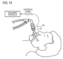
- Fig. 14 illustrates a use example of the airway adaptor 1A.
- the diffusing portion 18 prevents a jet stream from being generated in the second adaptor gas passage 12a, and therefore the accuracy of measurement of the ventilation volume is hardly lowered.
- a related-art differential pressure flowmeter when the sensitivity or accuracy of the flow rate measurement is to be adjusted, the adjustment is performed by adjusting the size of the opening of the orifice plate. In this method, in accordance with the adjustment of the size of the opening, the resistance to the fluid is easily changed.
- the at least two partition members are disposed in the gas passage along the axial direction of the tubular member in a state where the partition members are separated from one another by a predetermined distance.
- the partition members because of not only the resistance due to end surfaces of the partition members which intersect substantially perpendicularly with the axial direction of the tubular member, but also the side surfaces of the partition members which extend along the axial direction, the partition members generate a pressure loss of a given level or higher in the fluid (the expiration or the inspiration) flowing through the gas passage.
- the degree of a change in the resistance which is caused when the pressure loss is generated by increasing the areas of the side surfaces is smaller than that of a change in the resistance which is caused when the pressure loss is generated by increasing the areas of the end surfaces.
Landscapes
- Health & Medical Sciences (AREA)
- Life Sciences & Earth Sciences (AREA)
- Pulmonology (AREA)
- Veterinary Medicine (AREA)
- Public Health (AREA)
- General Health & Medical Sciences (AREA)
- Engineering & Computer Science (AREA)
- Biomedical Technology (AREA)
- Heart & Thoracic Surgery (AREA)
- Animal Behavior & Ethology (AREA)
- Physics & Mathematics (AREA)
- Surgery (AREA)
- Molecular Biology (AREA)
- Medical Informatics (AREA)
- Pathology (AREA)
- Biophysics (AREA)
- Physiology (AREA)
- Emergency Medicine (AREA)
- Anesthesiology (AREA)
- Hematology (AREA)
- Fluid Mechanics (AREA)
- General Physics & Mathematics (AREA)
- Measurement Of The Respiration, Hearing Ability, Form, And Blood Characteristics Of Living Organisms (AREA)
- Measuring Volume Flow (AREA)
Abstract
Description
- The presently disclosed subject matter relates to a respiratory flow rate sensor which measures the flow rate of the respiratory gas of the subject, and an airway adaptor which is to be used in the respiratory flow rate sensor.
- A ventilation method has been performed in which, with respect to a subject in a hypoventilated state or a respiratory arrest state, a mask with an air supply bag (an Ambu bag, a Jackson Rees bag, or the like) covers an area extending from the mouth cavity of the subject to the nasal cavity, and a medical person or the like presses the air supply bag to supply the air to the lungs of the subject (see
JP-A-2011-115543 - In the case where the related-art ventilation method is performed, when a gap exists between the mask and the face of the subject, ventilation is not adequately performed. In ventilation, therefore, a medical person or the like visually checks whether the chest of the subject expands or not, and whether the thorax is raised or not.
- When ventilation failure or the like occurs, an artificial respirator has been used.
- The visual check is effective in an adult in whom the ventilation volume is large. In the case of an infant or baby in whom the ventilation volume is small, however, it is sometimes difficult to perform the visual check. Therefore, the inventor of the present application tried to measure the flow rate in a subject under ventilation by using a related-art differential pressure flowmeter. However, there was the following problem.
- In order to obtain a differential pressure signal which is necessary for accurately measuring a small ventilation volume of an infant or a baby, the orifice (an opening of an orifice plate) of the flowmeter must be narrowed. When the orifice is narrowed, however, the resistance of the gas passage in the flowmeter is increased, and, because of the increased resistance, it is difficult for the infant, the baby, or the like to discharge the expiration.
- The presently disclosed subject matter may provide an airway adaptor and respiratory flow rate sensor which, while preventing the resistance of a gas passage from being increased, can obtain a differential pressure signal that is necessary for measuring a relatively small ventilation volume.
- The airway adaptor may include a tubular member to which a measuring section configured to measure a flow rate of a respiratory gas of a subject is to be attached. The tubular member includes: a gas passage through which the respiratory gas to pass; and a resistance portion which is configured to generate a differential pressure in the respiratory gas passing through the gas passage. The resistance portion includes at least two partition members which are disposed in the gas passage along an axial direction of the tubular member and which are separated from one another. Side surfaces of the partition members are separated from an inner wall surface of the gas passage.
-
-
Fig. 1 is a view illustrating an airway adaptor of an embodiment of the presently disclosed subject matter. -
Fig. 2 is a top view of the airway adaptor. -
Fig. 3 is a front view of the airway adaptor. -
Fig. 4 is a bottom view of the airway adaptor. -
Fig. 5 is a left side view of the airway adaptor. -
Fig. 6 is a right side view of the airway adaptor. -
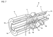
Fig. 7 is a fragmentary sectional view taken along lines A-A and B-B inFig. 1 . -
Fig. 8 is a sectional view taken along line C-C inFig. 2 . -
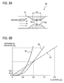
Figs. 9A and 9B are views illustrating the function of a related-art configuration. -
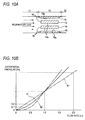
Figs. 10A and 10B are views illustrating the function of the configuration of the presently disclosed subject matter. -
Fig. 11 is a view illustrating an airway adaptor to which a measuring section is attached. -
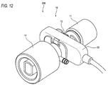
Fig. 12 is a view illustrating an airway adaptor to which a measuring section that is different from that shown inFig. 11 is attached. -
Fig. 13A is a sectional view of a modification of the airway adaptor, andFig. 13B is a left side view of the modification. -
Fig. 14 is a view illustrating a use example of the airway adaptor of the modification. - Hereinafter, an embodiment will be described in detail with reference to the drawings. An
airway adaptor 1 is used in, for example, measuring the flow rate of the respiratory gas of a subject who requires respiratory management. Particularly, theairway adaptor 1 may be used for a subject in whom the ventilation volume is small (for example, an infant, a baby, or an aged person). - As illustrated in
Figs. 1 to 8 , theairway adaptor 1 may include atubular member 10 which generally has an approximately tubular shape. A measuring section for measuring the flow rate of the respiratory gas is to be connected to thetubular member 10. - The
tubular member 10 is configured by afirst adaptor section 11, asecond adaptor section 12, and an attachingsection 13. - The
first adaptor section 11 is disposed in one end side of thetubular member 10, and has a cylindrical shape (seeFigs. 1 , and6 to 8 ). In thefirst adaptor section 11, a firstadaptor gas passage 11a through which the respiratory gas is to flow is disposed along the axial direction of thetubular member 10. In the embodiment, the firstadaptor gas passage 11a is formed into a rectangular shape. A firstadaptor connecting portion 11b which is formed so as to cover the firstadaptor gas passage 11a is disposed outside the firstadaptor gas passage 11a. - The
first adaptor section 11 is connected to an external apparatus (an example of the inspiration supplying section) such as an Ambu bag, a Jackson Rees bag, or an artificial respirator through the firstadaptor connecting portion 11b. The air (inspiration into the subject) supplied from the external apparatus is introduced into the firstadaptor gas passage 11a through an opening 11c of the firstadaptor gas passage 11a. - The
second adaptor section 12 is disposed in the other end side of thetubular member 10 which is opposite to thefirst adaptor section 11, and has a cylindrical shape (seeFigs. 1 ,5 ,7 , and8 ). Thesecond adaptor section 12 is formed into a cylindrical shape having a diameter which is larger than that of thefirst adaptor section 11. In thesecond adaptor section 12, a secondadaptor gas passage 12a through which the respiratory gas is to flow is disposed along the axial direction of thetubular member 10. In the embodiment, the secondadaptor gas passage 12a is formed into a rectangular shape. A secondadaptor connecting portion 12b which is formed so as to cover the secondadaptor gas passage 12a is disposed outside the secondadaptor gas passage 12a. - The
second adaptor section 12 is connected to an apparatus (an example of the expiration outputting section) on the side of the subject such as a tracheal tube or a mask through the secondadaptor connecting portion 12b. The air (expiration) discharged from the subject is introduced into the secondadaptor gas passage 12a through an opening 12c of the secondadaptor gas passage 12a. - The attaching
section 13 is disposed in a middle portion of thetubular member 10, and located between thefirst adaptor section 11 and thesecond adaptor section 12. In the attachingsection 13, an attaching-section gas passage 13a through which the respiratory gas is to flow is disposed along the axial direction of the tubular member 10 (seeFig. 8 ). - A plurality (in the embodiment, two) of plate-like members 14 (an example of the partition members) are disposed in the attaching-
section gas passage 13a (seeFigs. 5 to 8 ). The plate-like members 14 are juxtaposed to each other along the axial direction of thetubular member 10 in a state where they are separated from each other. In the embodiment, the two plate-like members 14 are disposed parallel to each other. The plate-like members 14 are disposed so that theside surfaces 14a of the plate-like members 14 are directed toward the front (or the back) of thetubular member 10. In the embodiment,projections 15 are formed on the inner wall of the attaching-section gas passage 13a to narrow (or constrict) the attaching-section gas passage 13a, and the two plate-like members 14 are disposed between the bothprojections 15. - The
side surfaces 14a of the plate-like members 14 are disposed in a state where the side surfaces are separated from the the inner wall surface (thesurfaces 15a of the projections 15) of the attaching-section gas passage 13a. The side surfaces 14a are disposed parallel to the axial direction of thetubular member 10. Since the plate-like members 14 are disposed, the interior of the attaching-section gas passage 13a has a configuration where the interior is partitioned into a plurality (in the embodiment, three) of gas passages which are juxtaposed to one another so as to extend along the axial direction of thetubular member 10. The six surfaces which are the sum of the both side surfaces of the two plate-like members 14 and thesurfaces 15a of the twoprojections 15 are disposed along the axial direction of the tubular member 10 (along the flow direction of the respiratory gas) - The members which are disposed in the attaching-
section gas passage 13a are not limited to the above-described plate-like members 14, as far as they have surfaces which extend along the axial direction of thetubular member 10. For example, a plurality of tubular members each having a curved surface may be disposed. -
Holes 14b are formed in substantially middle portions of the two plate-like members 14, respectively (seeFigs. 7 and8 ). Theholes 14b are disposed so as to be opposed to each other, and a detection light beam which is emitted from the outside of thetubular member 10 can pass through the holes.Windows 15b which are openings communicating with the attaching-section gas passage 13a are formed so as to be opposed to each other in the wall of the attaching section 13 (the walls of the portions where theprojections 15 are formed) (seeFigs. 2 ,7 , and8 ). Theholes 14b and thewindows 15b are formed so as to have a substantially same size, and arranged on the same axis. A measuring section which emits and receives the detection light beam to measure the concentration of a specific component of the respiratory gas can be attached to theportion 13b (seeFig. 3 ) where thewindows 15b of the attachingsection 13 are formed. - Pressure take-out
ports tubular member 10 are disposed in the both end sides of the attachingsection 13 in the axial direction of thetubular member 10, respectively (seeFigs. 1 ,3 ,4 , and8 ). The pressure take-outports section gas passage 13a. The measuring section for measuring the flow rate of the respiratory gas can be attached to the airway adaptor through the pressure take-outports - The first
adaptor gas passage 11a of thefirst adaptor section 11 is coupled to one end of the attaching-section gas passage 13a of the attaching section 13 (seeFigs. 7 and8 ). The secondadaptor gas passage 12a of thesecond adaptor section 12 is coupled to the other end of the attaching-section gas passage 13a which is opposite to the firstadaptor gas passage 11a. In thetubular member 10, the firstadaptor gas passage 11a, the attaching-section gas passage 13a, and the secondadaptor gas passage 12a form the gas passage which communicatively extends in the axial direction of thetubular member 10. - In the gas passage of the thus configured
tubular member 10, the inspiration which is supplied from the external apparatus toward the subject passes through the firstadaptor gas passage 11a and the attaching-section gas passage 13a, and then reaches the secondadaptor gas passage 12a. The expiration discharged from the subject passes through the secondadaptor gas passage 12a and the attaching-section gas passage 13a to reach the firstadaptor gas passage 11a. - In the case where respiratory ventilation of the patient is performed, the flow rate is measured based on the differential pressure by using a respiratory flow rate sensor. There is available an orifice flow meter in which an orifice plate having an opening is used, and the flow rate is calculated based on the difference between the pressures of the respiratory gas in front and rear of the orifice plate. In the respiratory gas, the relationship of the flow rate and the differential pressure is indicated by following
Expression 1.
- Among subjects who are to be subjected to respiratory ventilation, there are not only adults in whom the ventilation volume is relatively large, but also subjects in whom the ventilation volume is small, such as infants, babies, and aged persons. In the case where respiratory ventilation is performed on an infant, baby, or the like in whom the ventilation volume is small, it is particularly important to accurately adjust the ventilation volume. In order to obtain a differential pressure signal which is necessary for accurately measuring the ventilation volume, the opening of the orifice plate must be narrowed. When the opening is narrowed, however, the resistance of the gas passage in the flowmeter is increased, and, because of the increased resistance, it is difficult for the infant, the baby, or the like to discharge the expiration.
- Therefore, the inventor has studied a configuration where a differential pressure signal which is necessary for accurately measuring the ventilation volume can be obtained, and an infant, baby, or the like can discharge the expiration without difficulty. In a configuration for obtaining a necessary a differential pressure signal, then, attention has focused on factors other than the aperture (size) of the opening.
-
Fig. 9A illustrates an example of atubular member 50 in whichprojections 52 are opposedly disposed on the inner wall of agas passage 51. Each of theprojections 52 has a length Lo extending along the flow direction of the respiratory gas.Fig. 9B illustrates a graph of the relationship between the flow rate and the differential pressure in the case where the respiratory gas flows through thegas passage 51 having the configuration ofFig. 9A . In this case, the relationship between the flow rate (y) and the differential pressure (x) can be modeled by, for example, a quadratic function expression of y = ax2 + bx. - In the case where the flow rate is measured based on the differential pressure, in order to ensure the measurement accuracy, it is preferable that the relationship between the flow rate and the differential pressure is the relationship of a
linear function line 61 in the graph ofFig. 9B . In existing respiratory flow rate sensors which measure the flow rate of the respiratory gas, it is often that the measurement is performed in a range where the ventilation volume is relatively large (for example, a flow rate of 1.0 [L/S] or more). In the range, the value is changed in a manner similar to thelinear function line 61 as indicated by aquadratic function curve 62 in the graph ofFig. 9B . In a range where the ventilation volume is relatively small (for example, a flow rate of 1.0 [L/S] or less), however, the value is changed remotely from thelinear function line 61 as indicated by the quadratic function curve 62 (the differential pressure is less changed as compared with a change of the flow rate). In the range where the value is changed in this manner, in the case where noises are caused in the differential pressure output by external factors or the like, the value of the flow rate which is calculated based on the differential pressure is likely to be unstable. - In such a case, also in the configuration of
Fig. 9A , when the heights of theprojections 52 are changed in the directions of the arrows 53 (the aperture of thegas passage 51 is changed), it is possible to cause the value of the differential pressure in the range where the flow rate is 1.0 [L/S] or less, to become close to thelinear function line 61 as indicated by aquadratic function curve 63. When only the size (aperture) of thegas passage 51 is changed, however, the resistance to the respiratory gas flowing through thegas passage 51 is largely increased. Moreover, the differential pressure is largely changed in a range where a large flow rate is large, and therefore the measurement in the range of a large flow rate is hardly performed. - In the analysis in which actual measurements are performed, and the quadratic function curve (y = ax2 + bx) is approximated by a linear function line, the inventor has focused attention on the fact that the shifting of the quadratic function curve is affected by the surface areas of the
projections 52 having the length Lo in addition to the aperture (size) of thegas passage 51. - As illustrated in
Fig. 10A , therefore, the plate-like members 14 having the side surfaces 14a which extend along the flow direction of the respiratory gas are placed between theprojections 15. In the configuration, the end surfaces 16 of the plate-like members 14 and theprojections 15, the side surfaces 14a of the plate-like members 14, and the side surfaces 15a of theprojections 15 are elements which generate a resistance to the flow of the respiratory gas. As a result of actual measurements, the inventor has found that, when the areas of the end surfaces 16 (the aperture of the attaching-section gas passage 13a) are changed, the resistance to the respiratory gas is largely increased in the same manner as described above, and, when the areas of the side surfaces 14a are changed, by contrast, the relationship (the quadratic function curve) between the differential pressure and the flow rate can be adjusted while preventing the resistance to the respiratory gas from being increased. The inventor has further found that, when the adjustment is performed, while the value of the differential pressure in the range of a flow rate of 1.0 [L/S] or less is made close to thelinear function line 61, the value of the differential pressure in the range of a flow rate of 1.0 [L/S] or more can be maintained at a value which is close to thelinear function line 61, as indicated by aquadratic function curve 17 inFig. 10B . - According to the configuration of the presently disclosed subject matter, as the resistance portion, the at least two plate-
like members 14 are disposed in the gas passage along the axial direction of thetubular member 10 in the state where the plate-like members are separated from one another by a predetermined distance. In this case, it is considered that, because of not only the resistance due to the end surfaces 16 of the plate-like members 14 and theprojections 15 which intersect substantially perpendicularly with the axial direction of thetubular member 10, but also the side surfaces 14a of the plate-like members 14 andside surfaces 15a of theprojections 15 which extend along the axial direction, a pressure loss of a given level or higher is generated in the respiratory gas flowing through the attaching-section gas passage 13a. When the surface areas of the side surfaces 14a are increased while maintaining the surface areas of the end surfaces 16 (the size of the attaching-section gas passage 13a in the form of apertures) of the end surfaces 16, therefore, a differential pressure signal which is necessary for measuring a relatively small ventilation volume can be obtained while the resistance in the attaching-section gas passage 13a is prevented from being increased. As a result, even when noises are caused in the differential pressure output by external factors or the like, the flow rate which is calculated based on the differential pressure is less varied, and has a relatively stable value. - Since the side surfaces 14a of the plate-
like members 14 are disposed parallel to the axial direction of thetubular member 10, moreover, a differential pressure signal which is necessary for measuring a relatively small ventilation volume can be obtained while further preventing the resistance in the attaching-section gas passage 13a from being increased. - Since the plate-
like members 14 are disposed parallel to each other, moreover, a necessary differential pressure signal can be obtained while further preventing the resistance from being increased. - Furthermore, the
holes 14b which allow the detection light beams that is emitted from the outside of thetubular member 10, to pass through the holes are formed in the plate-like members 14, respectively. When, for example, an optical sensor is attached, therefore, it is possible to measure the concentration of a gas contained in the expiration of the subject, such as carbon dioxide. - Inside the first
adaptor connecting portion 11b the size of which is set in accordance with the standard, the firstadaptor gas passage 11a is formed that corresponds in size to the attaching-section gas passage 13a in which the plate-like members 14 are disposed. Inside the secondadaptor connecting portion 12b, similarly, the secondadaptor gas passage 12a is formed. Therefore, it is possible to form a gas passage having a capacity which is suitable for a subject in whom the ventilation volume in one respiration is small, such as an infant, a baby, or an aged person. - When a measuring
section 20 which measures the flow rate of the respiratory gas is attached to thetubular member 10 as illustrated inFig. 11 , theairway adaptor 1 can be configured as a respiratoryflow rate sensor 100. - The measuring
section 20 is attached to the tubular member through the pressure take-outports section 13. One-end sides ofpressure ports section gas passage 13a throughrespective openings Figs. 2 and7 ) of the pressure take-outports pressure ports section 20 through the respective pressure take-outports like members 14 in the flow direction of the respiratory gas is sensed via thepressure ports section 20, and the flow rate of the respiratory gas flowing through thetubular member 10 is calculated. - According to the configuration, when an infant, a baby, or an aged person is ventilated, the medical person can determine whether the ventilation is appropriately performed or not, not by means of a visual check, but based on the output value of the respiratory flow rate sensor.
- When a measuring
section 30 which measures the concentration of a specific component of the respiratory gas is attached to thetubular member 10 as illustrated inFig. 12 , theairway adaptor 1 can be configured as a respiratorygas concentration sensor 200. - A recess (not shown) which opens into, for example, a rectangular shape is formed in the measuring
section 30. The measuringsection 30 is attached so as to clamp the attachingsection 13 in a direction perpendicular to the axial direction of thetubular member 10, through the recess. A light emitter (an LED or the like) and a light receiver are disposed in the recess of the measuringsection 30. When the measuring section is attached to the tubular member, the light emitter and the light receiver are placed at positions which are outside thewindows 15b of the attachingsection 13, respectively. An infrared light beam emitted from the light emitter traverses the attaching-section gas passage 13a while passing through thewindows 15b of the attachingsection 13 and theholes 14b of the plate-like members 14. In accordance with the concentration of a gas (for example, carbon dioxide) contained in the respiratory gas flowing through the attaching-section gas passage 13a, the absorption amount of the infrared light beam is changed, and therefore the intensity of the infrared light beam which is received by the light receiver is changed. When an output signal corresponding to the intensity of the received light beam is monitored, a predetermined gas component contained in the respiratory gas is detected. - According to the configuration, it is possible to measure the concentration of a gas such as carbon dioxide contained in the respiratory gas of the subject who is ventilated through the
airway adaptor 1. - The foregoing description of the embodiment has been made in order to facilitate understanding of the presently disclosed subject matter, and is not intended to limit the presently disclosed subject matter. It is a matter of course that the presently disclosed subject matter may be changed or improved without departing the spirit thereof, and includes equivalents thereof.
- For example,
Figs. 13A and 13B illustrate anairway adaptor 1A of a modification. In theairway adaptor 1A, a diffusingportion 18 is disposed inside theopening 12c of the secondadaptor gas passage 12a. Theairway adaptor 1A is configured in the same manner as the above-describedairway adaptor 1 except the disposition of the diffusingportion 18. The diffusingportion 18 in the modification is a rod-like member, and formed integrally with the secondadaptor gas passage 12a to partition theopening 12c into two areas. The diffusingportion 18 has a function of preventing a jet stream from being generated in the secondadaptor gas passage 12a. The shape and placement of the diffusingportion 18 may be adequately changed as far as they enable the diffusing portion to prevent a jet stream from being generated. - The
airway adaptor 1A exemplified inFigs. 13A and 13B is suitably used in an intubation tube.Fig. 14 illustrates a use example of theairway adaptor 1A. In the case where an intubation tube having a relatively small inner diameter is used, usually, there is a fear that a jet stream is generated in an airway adaptor, and the accuracy of measurement of the ventilation volume is lowered by the influence of the jet stream. In theairway adaptor 1A exemplified inFigs. 13A and 13B , however, the diffusingportion 18 prevents a jet stream from being generated in the secondadaptor gas passage 12a, and therefore the accuracy of measurement of the ventilation volume is hardly lowered. - In a related-art differential pressure flowmeter, when the sensitivity or accuracy of the flow rate measurement is to be adjusted, the adjustment is performed by adjusting the size of the opening of the orifice plate. In this method, in accordance with the adjustment of the size of the opening, the resistance to the fluid is easily changed.
- According to an aspect of the presently disclosed subject matter, as the resistance portion, the at least two partition members are disposed in the gas passage along the axial direction of the tubular member in a state where the partition members are separated from one another by a predetermined distance. In this case, because of not only the resistance due to end surfaces of the partition members which intersect substantially perpendicularly with the axial direction of the tubular member, but also the side surfaces of the partition members which extend along the axial direction, the partition members generate a pressure loss of a given level or higher in the fluid (the expiration or the inspiration) flowing through the gas passage. In a state where the amount of the fluid flowing through the gas passage is small, when a pressure loss of a given level or higher is to be generated in the gas passage, for example, it is contemplated that the degree of a change in the resistance which is caused when the pressure loss is generated by increasing the areas of the side surfaces is smaller than that of a change in the resistance which is caused when the pressure loss is generated by increasing the areas of the end surfaces. When the partition members are disposed and placed along the axial direction of the tubular member, therefore, it is possible to obtain a differential pressure signal which is necessary for measuring a relatively small ventilation volume, while preventing the resistance of the gas passage from being increased.
Claims (7)
- An airway adaptor including a tubular member to which a measuring section configured to measure a flow rate of a respiratory gas of a subject is to be attached, wherein
the tubular member includes:a gas passage through which the respiratory gas to pass; anda resistance portion which is configured to generate a differential pressure in the respiratory gas passing through the gas passage,
the resistance portion includes at least two partition members which are disposed in the gas passage along an axial direction of the tubular member and which are separated from one another, and
side surfaces of the partition members are separated from an inner wall surface of the gas passage. - The airway adaptor according to claim 1, wherein
the side surfaces of the partition members are parallel to the axial direction of the tubular member. - The airway adaptor according to claim 1 or 2, wherein
the at least two partition members are disposed parallel to each other. - The airway adaptor according to any one of claims 1 to 3, wherein
a hole allowing a detection light beam which is to be emitted from an outside of the tubular member, to pass through the hole is formed in each of the partition members. - The airway adaptor according to any one of claims 1 to 4, wherein
a first adaptor section which is to be connected to an inspiration supplying section for supplying inspiration to the subject is disposed in one end side of the tubular member,
a second adaptor section which is to be connected to an expiration outputting section for outputting expiration from the subject is disposed in the other end side of the tubular member,
the first adaptor section includes: a first adaptor gas passage which is coupled to one end of the gas passage in which the partition members are disposed; and a first adaptor connecting portion which is formed to cover an outside of the first adaptor gas passage, and
the second adaptor section includes: a second adaptor gas passage which is coupled to the other end of the gas passage in which the partition members are disposed; and a second adaptor connecting portion which is formed to cover an outside of the second adaptor gas passage. - The airway adaptor according to claim 5, wherein
a diffusing portion which is configured to diffuse air passing through the second adaptor gas passage is disposed in the second adaptor gas passage. - A respiratory flow rate sensor comprising:the airway adaptor according to any one of claims 1 to 6; andthe measuring section which is configured measure the flow rate of the respiratory gas of the subject.
Applications Claiming Priority (1)
| Application Number | Priority Date | Filing Date | Title |
|---|---|---|---|
| JP2015186785A JP6644505B2 (en) | 2015-09-24 | 2015-09-24 | Airway adapter and respiratory air flow sensor |
Publications (2)
| Publication Number | Publication Date |
|---|---|
| EP3146992A1 true EP3146992A1 (en) | 2017-03-29 |
| EP3146992B1 EP3146992B1 (en) | 2019-02-06 |
Family
ID=56936347
Family Applications (1)
| Application Number | Title | Priority Date | Filing Date |
|---|---|---|---|
| EP16188936.5A Active EP3146992B1 (en) | 2015-09-24 | 2016-09-15 | Airway adaptor and respiratory flow rate sensor |
Country Status (3)
| Country | Link |
|---|---|
| US (1) | US11850036B2 (en) |
| EP (1) | EP3146992B1 (en) |
| JP (1) | JP6644505B2 (en) |
Cited By (1)
| Publication number | Priority date | Publication date | Assignee | Title |
|---|---|---|---|---|
| EP4194040A1 (en) * | 2021-12-10 | 2023-06-14 | GE Precision Healthcare LLC | Airway adaptor with liquid containment path |
Families Citing this family (5)
| Publication number | Priority date | Publication date | Assignee | Title |
|---|---|---|---|---|
| JP7109534B2 (en) * | 2017-07-26 | 2022-07-29 | シプラ・リミテッド | Spirometer Flow Sensing Arrangement |
| EP3745095B1 (en) * | 2018-02-23 | 2023-07-26 | Nanjing Exactra Automation Control Technology Co., Ltd. | Throttling component and rectification and flow measurement device |
| CN110464365B (en) * | 2018-05-10 | 2022-08-12 | 深圳先进技术研究院 | A kind of attention determination method, apparatus, device and storage medium |
| USD1031014S1 (en) * | 2019-10-07 | 2024-06-11 | Raumedic Ag | Respiration device |
| JP7417014B2 (en) * | 2020-08-31 | 2024-01-18 | ブリーシングス カンパニー リミテッド | Mouthpiece assembly for respiration measuring device |
Citations (5)
| Publication number | Priority date | Publication date | Assignee | Title |
|---|---|---|---|---|
| US5979247A (en) * | 1996-10-22 | 1999-11-09 | Nihon Kohden Corporation | Flow sensor having a fixed resistance and a variable resistance |
| US6512581B1 (en) * | 1998-06-19 | 2003-01-28 | Nihon Kohden Corporation | Respiratory gas sensor |
| US20110028858A1 (en) * | 2009-02-17 | 2011-02-03 | Nihon Kohden Corporation | Gas flow system, adaptor, and method |
| JP2011115543A (en) | 2009-10-28 | 2011-06-16 | Nippon Koden Corp | Oxygen mask |
| US20120192642A1 (en) * | 2011-01-31 | 2012-08-02 | Honeywell International Inc. | Flow sensor assembly with integral bypass channel |
Family Cites Families (12)
| Publication number | Priority date | Publication date | Assignee | Title |
|---|---|---|---|---|
| US5379650A (en) | 1992-09-23 | 1995-01-10 | Korr Medical Technologies Inc. | Differential pressure sensor for respiratory monitoring |
| US5535633A (en) | 1992-09-23 | 1996-07-16 | Korr Medical Technologies, Inc. | Differential pressure sensor for respiratory monitoring |
| US5347843A (en) | 1992-09-23 | 1994-09-20 | Korr Medical Technologies Inc. | Differential pressure flowmeter with enhanced signal processing for respiratory flow measurement |
| US7335164B2 (en) | 1996-07-15 | 2008-02-26 | Ntc Technology, Inc. | Multiple function airway adapter |
| US6325978B1 (en) | 1998-08-04 | 2001-12-04 | Ntc Technology Inc. | Oxygen monitoring and apparatus |
| US20070225612A1 (en) | 1996-07-15 | 2007-09-27 | Mace Leslie E | Metabolic measurements system including a multiple function airway adapter |
| US20100036272A1 (en) | 1996-07-15 | 2010-02-11 | Koninklijke Philips Electronics N.V. | Metabolic measure system including a multiple function airway adapter |
| US6815211B1 (en) | 1998-08-04 | 2004-11-09 | Ntc Technology | Oxygen monitoring methods and apparatus (I) |
| US5789660A (en) | 1996-07-15 | 1998-08-04 | Novametrix Medical Systems, Inc. | Multiple function airway adapter |
| US6601460B1 (en) * | 1998-06-10 | 2003-08-05 | Peter Albert Materna | Flowmeter based on pressure drop across parallel geometry using boundary layer flow including Reynolds numbers above the laminar range |
| EP2522276A1 (en) * | 2011-05-13 | 2012-11-14 | General Electric Company | Airway adapter and gas analyzer for measuring oxygen concentration of a respiratory gas |
| US10694978B2 (en) * | 2015-05-14 | 2020-06-30 | Invoy Holdings, Llc | Breath analysis system, device and method employing nanoparticle-based sensor |
-
2015
- 2015-09-24 JP JP2015186785A patent/JP6644505B2/en active Active
-
2016
- 2016-09-15 EP EP16188936.5A patent/EP3146992B1/en active Active
- 2016-09-15 US US15/266,463 patent/US11850036B2/en active Active
Patent Citations (5)
| Publication number | Priority date | Publication date | Assignee | Title |
|---|---|---|---|---|
| US5979247A (en) * | 1996-10-22 | 1999-11-09 | Nihon Kohden Corporation | Flow sensor having a fixed resistance and a variable resistance |
| US6512581B1 (en) * | 1998-06-19 | 2003-01-28 | Nihon Kohden Corporation | Respiratory gas sensor |
| US20110028858A1 (en) * | 2009-02-17 | 2011-02-03 | Nihon Kohden Corporation | Gas flow system, adaptor, and method |
| JP2011115543A (en) | 2009-10-28 | 2011-06-16 | Nippon Koden Corp | Oxygen mask |
| US20120192642A1 (en) * | 2011-01-31 | 2012-08-02 | Honeywell International Inc. | Flow sensor assembly with integral bypass channel |
Cited By (1)
| Publication number | Priority date | Publication date | Assignee | Title |
|---|---|---|---|---|
| EP4194040A1 (en) * | 2021-12-10 | 2023-06-14 | GE Precision Healthcare LLC | Airway adaptor with liquid containment path |
Also Published As
| Publication number | Publication date |
|---|---|
| US20170086708A1 (en) | 2017-03-30 |
| JP2017060554A (en) | 2017-03-30 |
| US11850036B2 (en) | 2023-12-26 |
| JP6644505B2 (en) | 2020-02-12 |
| EP3146992B1 (en) | 2019-02-06 |
Similar Documents
| Publication | Publication Date | Title |
|---|---|---|
| EP3146992B1 (en) | Airway adaptor and respiratory flow rate sensor | |
| US8286504B2 (en) | Arrangement for improving accuracy of pressure measurement and flow sensor | |
| CN101204328B (en) | Respiratory monitoring with cannula receiving respiratory airflows | |
| US6312389B1 (en) | Multiple function airway adapter | |
| US8915861B2 (en) | Adaptor for collecting expiratory information and biological information processing system using the same | |
| US7172557B1 (en) | Spirometer, display and method | |
| US9468734B2 (en) | Gas flow system, adaptor, and method | |
| US20070113850A1 (en) | Respiratory monitoring with cannula receiving respiratory airflows and differential pressure transducer | |
| US20200093399A1 (en) | Breath analyzer device | |
| US20100152580A1 (en) | Lung diagnosis apparatus with four ultrasound elements | |
| US6512581B1 (en) | Respiratory gas sensor | |
| US20070113848A1 (en) | Respiratory monitoring with cannula receiving respiratory airflows and exhaled gases | |
| KR20210008956A (en) | Larynx mask apparatus | |
| EP4584558B1 (en) | Pitot tube for measuring high and low respiratory flow rates | |
| US11304625B2 (en) | Gas sensor kit and device wearable on face | |
| CN114945320B (en) | Device for breathing apparatus | |
| US20130345590A1 (en) | Apparatus for quantifying expiratory and inspiratory airflow | |
| EP2720005A1 (en) | Arrangement for a pressure measurement of a breathing gas flowing along a flow channel | |
| US20230330377A1 (en) | Method and apparatus for monitoring a nasal high-flow therapy system | |
| ES2980508T3 (en) | Respiration monitoring device to produce a capnogram | |
| JP2021035441A (en) | Respiratory flow measuring device | |
| Ventilation | Dependency of Tidal Volume on Mean Airway Pressure in High-Frequency | |
| DE3539719A1 (en) | Breathing monitor for artificially ventilated and spontaneously breathing premature or newly born babies and infants | |
| JP2001066243A (en) | Respiratory gas sensor | |
| SE545956C2 (en) | A device for a respiration arrangement providing a flow constriction with a laminar flow section comprising a plurality of elongated channels |
Legal Events
| Date | Code | Title | Description |
|---|---|---|---|
| PUAI | Public reference made under article 153(3) epc to a published international application that has entered the european phase |
Free format text: ORIGINAL CODE: 0009012 |
|
| STAA | Information on the status of an ep patent application or granted ep patent |
Free format text: STATUS: THE APPLICATION HAS BEEN PUBLISHED |
|
| AK | Designated contracting states |
Kind code of ref document: A1 Designated state(s): AL AT BE BG CH CY CZ DE DK EE ES FI FR GB GR HR HU IE IS IT LI LT LU LV MC MK MT NL NO PL PT RO RS SE SI SK SM TR |
|
| AX | Request for extension of the european patent |
Extension state: BA ME |
|
| STAA | Information on the status of an ep patent application or granted ep patent |
Free format text: STATUS: REQUEST FOR EXAMINATION WAS MADE |
|
| 17P | Request for examination filed |
Effective date: 20170914 |
|
| RBV | Designated contracting states (corrected) |
Designated state(s): AL AT BE BG CH CY CZ DE DK EE ES FI FR GB GR HR HU IE IS IT LI LT LU LV MC MK MT NL NO PL PT RO RS SE SI SK SM TR |
|
| GRAJ | Information related to disapproval of communication of intention to grant by the applicant or resumption of examination proceedings by the epo deleted |
Free format text: ORIGINAL CODE: EPIDOSDIGR1 |
|
| GRAP | Despatch of communication of intention to grant a patent |
Free format text: ORIGINAL CODE: EPIDOSNIGR1 |
|
| GRAP | Despatch of communication of intention to grant a patent |
Free format text: ORIGINAL CODE: EPIDOSNIGR1 |
|
| STAA | Information on the status of an ep patent application or granted ep patent |
Free format text: STATUS: GRANT OF PATENT IS INTENDED |
|
| INTG | Intention to grant announced |
Effective date: 20180824 |
|
| INTC | Intention to grant announced (deleted) | ||
| INTG | Intention to grant announced |
Effective date: 20180905 |
|
| GRAJ | Information related to disapproval of communication of intention to grant by the applicant or resumption of examination proceedings by the epo deleted |
Free format text: ORIGINAL CODE: EPIDOSDIGR1 |
|
| STAA | Information on the status of an ep patent application or granted ep patent |
Free format text: STATUS: REQUEST FOR EXAMINATION WAS MADE |
|
| GRAR | Information related to intention to grant a patent recorded |
Free format text: ORIGINAL CODE: EPIDOSNIGR71 |
|
| GRAS | Grant fee paid |
Free format text: ORIGINAL CODE: EPIDOSNIGR3 |
|
| STAA | Information on the status of an ep patent application or granted ep patent |
Free format text: STATUS: GRANT OF PATENT IS INTENDED |
|
| INTC | Intention to grant announced (deleted) | ||
| GRAA | (expected) grant |
Free format text: ORIGINAL CODE: 0009210 |
|
| STAA | Information on the status of an ep patent application or granted ep patent |
Free format text: STATUS: THE PATENT HAS BEEN GRANTED |
|
| INTG | Intention to grant announced |
Effective date: 20181219 |
|
| AK | Designated contracting states |
Kind code of ref document: B1 Designated state(s): AL AT BE BG CH CY CZ DE DK EE ES FI FR GB GR HR HU IE IS IT LI LT LU LV MC MK MT NL NO PL PT RO RS SE SI SK SM TR |
|
| REG | Reference to a national code |
Ref country code: GB Ref legal event code: FG4D |
|
| REG | Reference to a national code |
Ref country code: CH Ref legal event code: EP Ref country code: AT Ref legal event code: REF Ref document number: 1094460 Country of ref document: AT Kind code of ref document: T Effective date: 20190215 |
|
| REG | Reference to a national code |
Ref country code: IE Ref legal event code: FG4D |
|
| REG | Reference to a national code |
Ref country code: DE Ref legal event code: R096 Ref document number: 602016009786 Country of ref document: DE |
|
| REG | Reference to a national code |
Ref country code: NL Ref legal event code: MP Effective date: 20190206 |
|
| REG | Reference to a national code |
Ref country code: LT Ref legal event code: MG4D |
|
| PG25 | Lapsed in a contracting state [announced via postgrant information from national office to epo] |
Ref country code: FI Free format text: LAPSE BECAUSE OF FAILURE TO SUBMIT A TRANSLATION OF THE DESCRIPTION OR TO PAY THE FEE WITHIN THE PRESCRIBED TIME-LIMIT Effective date: 20190206 Ref country code: SE Free format text: LAPSE BECAUSE OF FAILURE TO SUBMIT A TRANSLATION OF THE DESCRIPTION OR TO PAY THE FEE WITHIN THE PRESCRIBED TIME-LIMIT Effective date: 20190206 Ref country code: NO Free format text: LAPSE BECAUSE OF FAILURE TO SUBMIT A TRANSLATION OF THE DESCRIPTION OR TO PAY THE FEE WITHIN THE PRESCRIBED TIME-LIMIT Effective date: 20190506 Ref country code: PT Free format text: LAPSE BECAUSE OF FAILURE TO SUBMIT A TRANSLATION OF THE DESCRIPTION OR TO PAY THE FEE WITHIN THE PRESCRIBED TIME-LIMIT Effective date: 20190606 Ref country code: LT Free format text: LAPSE BECAUSE OF FAILURE TO SUBMIT A TRANSLATION OF THE DESCRIPTION OR TO PAY THE FEE WITHIN THE PRESCRIBED TIME-LIMIT Effective date: 20190206 Ref country code: NL Free format text: LAPSE BECAUSE OF FAILURE TO SUBMIT A TRANSLATION OF THE DESCRIPTION OR TO PAY THE FEE WITHIN THE PRESCRIBED TIME-LIMIT Effective date: 20190206 |
|
| REG | Reference to a national code |
Ref country code: AT Ref legal event code: MK05 Ref document number: 1094460 Country of ref document: AT Kind code of ref document: T Effective date: 20190206 |
|
| PG25 | Lapsed in a contracting state [announced via postgrant information from national office to epo] |
Ref country code: HR Free format text: LAPSE BECAUSE OF FAILURE TO SUBMIT A TRANSLATION OF THE DESCRIPTION OR TO PAY THE FEE WITHIN THE PRESCRIBED TIME-LIMIT Effective date: 20190206 Ref country code: RS Free format text: LAPSE BECAUSE OF FAILURE TO SUBMIT A TRANSLATION OF THE DESCRIPTION OR TO PAY THE FEE WITHIN THE PRESCRIBED TIME-LIMIT Effective date: 20190206 Ref country code: BG Free format text: LAPSE BECAUSE OF FAILURE TO SUBMIT A TRANSLATION OF THE DESCRIPTION OR TO PAY THE FEE WITHIN THE PRESCRIBED TIME-LIMIT Effective date: 20190506 Ref country code: LV Free format text: LAPSE BECAUSE OF FAILURE TO SUBMIT A TRANSLATION OF THE DESCRIPTION OR TO PAY THE FEE WITHIN THE PRESCRIBED TIME-LIMIT Effective date: 20190206 Ref country code: GR Free format text: LAPSE BECAUSE OF FAILURE TO SUBMIT A TRANSLATION OF THE DESCRIPTION OR TO PAY THE FEE WITHIN THE PRESCRIBED TIME-LIMIT Effective date: 20190507 Ref country code: IS Free format text: LAPSE BECAUSE OF FAILURE TO SUBMIT A TRANSLATION OF THE DESCRIPTION OR TO PAY THE FEE WITHIN THE PRESCRIBED TIME-LIMIT Effective date: 20190606 |
|
| PG25 | Lapsed in a contracting state [announced via postgrant information from national office to epo] |
Ref country code: SK Free format text: LAPSE BECAUSE OF FAILURE TO SUBMIT A TRANSLATION OF THE DESCRIPTION OR TO PAY THE FEE WITHIN THE PRESCRIBED TIME-LIMIT Effective date: 20190206 Ref country code: RO Free format text: LAPSE BECAUSE OF FAILURE TO SUBMIT A TRANSLATION OF THE DESCRIPTION OR TO PAY THE FEE WITHIN THE PRESCRIBED TIME-LIMIT Effective date: 20190206 Ref country code: DK Free format text: LAPSE BECAUSE OF FAILURE TO SUBMIT A TRANSLATION OF THE DESCRIPTION OR TO PAY THE FEE WITHIN THE PRESCRIBED TIME-LIMIT Effective date: 20190206 Ref country code: EE Free format text: LAPSE BECAUSE OF FAILURE TO SUBMIT A TRANSLATION OF THE DESCRIPTION OR TO PAY THE FEE WITHIN THE PRESCRIBED TIME-LIMIT Effective date: 20190206 Ref country code: IT Free format text: LAPSE BECAUSE OF FAILURE TO SUBMIT A TRANSLATION OF THE DESCRIPTION OR TO PAY THE FEE WITHIN THE PRESCRIBED TIME-LIMIT Effective date: 20190206 Ref country code: AL Free format text: LAPSE BECAUSE OF FAILURE TO SUBMIT A TRANSLATION OF THE DESCRIPTION OR TO PAY THE FEE WITHIN THE PRESCRIBED TIME-LIMIT Effective date: 20190206 Ref country code: ES Free format text: LAPSE BECAUSE OF FAILURE TO SUBMIT A TRANSLATION OF THE DESCRIPTION OR TO PAY THE FEE WITHIN THE PRESCRIBED TIME-LIMIT Effective date: 20190206 Ref country code: CZ Free format text: LAPSE BECAUSE OF FAILURE TO SUBMIT A TRANSLATION OF THE DESCRIPTION OR TO PAY THE FEE WITHIN THE PRESCRIBED TIME-LIMIT Effective date: 20190206 |
|
| REG | Reference to a national code |
Ref country code: DE Ref legal event code: R097 Ref document number: 602016009786 Country of ref document: DE |
|
| PG25 | Lapsed in a contracting state [announced via postgrant information from national office to epo] |
Ref country code: SM Free format text: LAPSE BECAUSE OF FAILURE TO SUBMIT A TRANSLATION OF THE DESCRIPTION OR TO PAY THE FEE WITHIN THE PRESCRIBED TIME-LIMIT Effective date: 20190206 Ref country code: PL Free format text: LAPSE BECAUSE OF FAILURE TO SUBMIT A TRANSLATION OF THE DESCRIPTION OR TO PAY THE FEE WITHIN THE PRESCRIBED TIME-LIMIT Effective date: 20190206 |
|
| PLBE | No opposition filed within time limit |
Free format text: ORIGINAL CODE: 0009261 |
|
| STAA | Information on the status of an ep patent application or granted ep patent |
Free format text: STATUS: NO OPPOSITION FILED WITHIN TIME LIMIT |
|
| PG25 | Lapsed in a contracting state [announced via postgrant information from national office to epo] |
Ref country code: AT Free format text: LAPSE BECAUSE OF FAILURE TO SUBMIT A TRANSLATION OF THE DESCRIPTION OR TO PAY THE FEE WITHIN THE PRESCRIBED TIME-LIMIT Effective date: 20190206 |
|
| 26N | No opposition filed |
Effective date: 20191107 |
|
| PG25 | Lapsed in a contracting state [announced via postgrant information from national office to epo] |
Ref country code: SI Free format text: LAPSE BECAUSE OF FAILURE TO SUBMIT A TRANSLATION OF THE DESCRIPTION OR TO PAY THE FEE WITHIN THE PRESCRIBED TIME-LIMIT Effective date: 20190206 |
|
| PG25 | Lapsed in a contracting state [announced via postgrant information from national office to epo] |
Ref country code: TR Free format text: LAPSE BECAUSE OF FAILURE TO SUBMIT A TRANSLATION OF THE DESCRIPTION OR TO PAY THE FEE WITHIN THE PRESCRIBED TIME-LIMIT Effective date: 20190206 |
|
| PG25 | Lapsed in a contracting state [announced via postgrant information from national office to epo] |
Ref country code: MC Free format text: LAPSE BECAUSE OF FAILURE TO SUBMIT A TRANSLATION OF THE DESCRIPTION OR TO PAY THE FEE WITHIN THE PRESCRIBED TIME-LIMIT Effective date: 20190206 |
|
| REG | Reference to a national code |
Ref country code: CH Ref legal event code: PL |
|
| PG25 | Lapsed in a contracting state [announced via postgrant information from national office to epo] |
Ref country code: IE Free format text: LAPSE BECAUSE OF NON-PAYMENT OF DUE FEES Effective date: 20190915 Ref country code: LU Free format text: LAPSE BECAUSE OF NON-PAYMENT OF DUE FEES Effective date: 20190915 Ref country code: LI Free format text: LAPSE BECAUSE OF NON-PAYMENT OF DUE FEES Effective date: 20190930 Ref country code: CH Free format text: LAPSE BECAUSE OF NON-PAYMENT OF DUE FEES Effective date: 20190930 |
|
| REG | Reference to a national code |
Ref country code: BE Ref legal event code: MM Effective date: 20190930 |
|
| PG25 | Lapsed in a contracting state [announced via postgrant information from national office to epo] |
Ref country code: BE Free format text: LAPSE BECAUSE OF NON-PAYMENT OF DUE FEES Effective date: 20190930 |
|
| PG25 | Lapsed in a contracting state [announced via postgrant information from national office to epo] |
Ref country code: FR Free format text: LAPSE BECAUSE OF NON-PAYMENT OF DUE FEES Effective date: 20190930 |
|
| GBPC | Gb: european patent ceased through non-payment of renewal fee |
Effective date: 20200915 |
|
| PG25 | Lapsed in a contracting state [announced via postgrant information from national office to epo] |
Ref country code: CY Free format text: LAPSE BECAUSE OF FAILURE TO SUBMIT A TRANSLATION OF THE DESCRIPTION OR TO PAY THE FEE WITHIN THE PRESCRIBED TIME-LIMIT Effective date: 20190206 |
|
| PG25 | Lapsed in a contracting state [announced via postgrant information from national office to epo] |
Ref country code: MT Free format text: LAPSE BECAUSE OF FAILURE TO SUBMIT A TRANSLATION OF THE DESCRIPTION OR TO PAY THE FEE WITHIN THE PRESCRIBED TIME-LIMIT Effective date: 20190206 Ref country code: HU Free format text: LAPSE BECAUSE OF FAILURE TO SUBMIT A TRANSLATION OF THE DESCRIPTION OR TO PAY THE FEE WITHIN THE PRESCRIBED TIME-LIMIT; INVALID AB INITIO Effective date: 20160915 |
|
| PG25 | Lapsed in a contracting state [announced via postgrant information from national office to epo] |
Ref country code: GB Free format text: LAPSE BECAUSE OF NON-PAYMENT OF DUE FEES Effective date: 20200915 |
|
| PG25 | Lapsed in a contracting state [announced via postgrant information from national office to epo] |
Ref country code: MK Free format text: LAPSE BECAUSE OF FAILURE TO SUBMIT A TRANSLATION OF THE DESCRIPTION OR TO PAY THE FEE WITHIN THE PRESCRIBED TIME-LIMIT Effective date: 20190206 |
|
| PGFP | Annual fee paid to national office [announced via postgrant information from national office to epo] |
Ref country code: DE Payment date: 20250730 Year of fee payment: 10 |