EP3146922A1 - Implantable insert sleeve - Google Patents
Implantable insert sleeve Download PDFInfo
- Publication number
- EP3146922A1 EP3146922A1 EP16198164.2A EP16198164A EP3146922A1 EP 3146922 A1 EP3146922 A1 EP 3146922A1 EP 16198164 A EP16198164 A EP 16198164A EP 3146922 A1 EP3146922 A1 EP 3146922A1
- Authority
- EP
- European Patent Office
- Prior art keywords
- insert
- insert sleeve
- hole
- implant
- bone
- Prior art date
- Legal status (The legal status is an assumption and is not a legal conclusion. Google has not performed a legal analysis and makes no representation as to the accuracy of the status listed.)
- Granted
Links
Images


Classifications
-
- A—HUMAN NECESSITIES
- A61—MEDICAL OR VETERINARY SCIENCE; HYGIENE
- A61B—DIAGNOSIS; SURGERY; IDENTIFICATION
- A61B17/00—Surgical instruments, devices or methods
- A61B17/56—Surgical instruments or methods for treatment of bones or joints; Devices specially adapted therefor
- A61B17/58—Surgical instruments or methods for treatment of bones or joints; Devices specially adapted therefor for osteosynthesis, e.g. bone plates, screws or setting implements
- A61B17/68—Internal fixation devices, including fasteners and spinal fixators, even if a part thereof projects from the skin
- A61B17/80—Cortical plates, i.e. bone plates; Instruments for holding or positioning cortical plates, or for compressing bones attached to cortical plates
- A61B17/8033—Cortical plates, i.e. bone plates; Instruments for holding or positioning cortical plates, or for compressing bones attached to cortical plates having indirect contact with screw heads, or having contact with screw heads maintained with the aid of additional components, e.g. nuts, wedges or head covers
- A61B17/8047—Cortical plates, i.e. bone plates; Instruments for holding or positioning cortical plates, or for compressing bones attached to cortical plates having indirect contact with screw heads, or having contact with screw heads maintained with the aid of additional components, e.g. nuts, wedges or head covers wherein the additional element surrounds the screw head in the plate hole
-
- A—HUMAN NECESSITIES
- A61—MEDICAL OR VETERINARY SCIENCE; HYGIENE
- A61B—DIAGNOSIS; SURGERY; IDENTIFICATION
- A61B17/00—Surgical instruments, devices or methods
- A61B17/56—Surgical instruments or methods for treatment of bones or joints; Devices specially adapted therefor
- A61B17/58—Surgical instruments or methods for treatment of bones or joints; Devices specially adapted therefor for osteosynthesis, e.g. bone plates, screws or setting implements
- A61B17/68—Internal fixation devices, including fasteners and spinal fixators, even if a part thereof projects from the skin
- A61B17/84—Fasteners therefor or fasteners being internal fixation devices
- A61B17/86—Pins or screws or threaded wires; nuts therefor
- A61B17/8695—Washers
-
- A—HUMAN NECESSITIES
- A61—MEDICAL OR VETERINARY SCIENCE; HYGIENE
- A61B—DIAGNOSIS; SURGERY; IDENTIFICATION
- A61B17/00—Surgical instruments, devices or methods
- A61B2017/00004—(bio)absorbable, (bio)resorbable or resorptive
-
- A—HUMAN NECESSITIES
- A61—MEDICAL OR VETERINARY SCIENCE; HYGIENE
- A61B—DIAGNOSIS; SURGERY; IDENTIFICATION
- A61B17/00—Surgical instruments, devices or methods
- A61B2017/00831—Material properties
- A61B2017/00946—Material properties malleable
Definitions
- the present disclosure relates to orthopedic implants, and more particularly, to insert sleeves designed for being inserted into a through hole of an implant.
- the fracture may be fixed by means of pins, screws, wires or plates after alignment of the individual bone fragments in their correct positions (repositioning).
- an osteosynthetic plate can be used which is fastened to the individual bone fragments by means of screws to hold the individual bone fragments in a fixed position with respect to one another.
- the present disclosure provides an insert sleeve designed for being inserted into a through hole of an implant.
- the insert sleeve comprises a body with a through hole defining an axial direction for receiving a bone anchoring element, in particular a bone screw.
- the body is made of a material having a first modulus of elasticity and includes multiple recesses arranged in circumferential direction around the through hole of the insert sleeve in particular for reducing a transverse stiffness of the insert sleeve and/or of the implant, in particular as compared to a same body without such multiple recesses and/or a same implant without such multiple recesses in a same body.
- the transverse stiffness is a stiffness in a direction transverse, in particular at least essentially perpendicular, in particular perpendicular, to the axial direction of the through hole of the insert sleeve.
- the multiple recesses are configured and arranged to increase the flexibility of the insert sleeve.
- the recesses are arranged and/or shaped such that the transverse stiffness is lower in a first transverse direction than in a second transverse direction.
- the transverse stiffness of the insert sleeve may be directional-dependent.
- the first transverse direction and the second transverse direction form a transverse plane, i.e. a plane transverse to the axial direction of the through hole of the insert sleeve.
- the first and second transverse directions may be perpendicular to each other.
- the insert sleeve may be inserted into a through hole of an elongate implant such that the first transverse direction coincides with a longitudinal axis of the elongate implant.
- At least one of the recesses is filled with a filler material having a second modulus of elasticity different from the first modulus of elasticity.
- the second modulus of elasticity may be smaller than the first modulus of elasticity.
- the filler material is bioresorbable.
- the filler material can be broken down by the body, i.e. will gradually resorb and be cleared from the body.
- the transverse stiffness of the insert sleeve may be time-dependent, in particular decrease over time. Consequently, more and more load initially borne by the implant may be transferred to the bone.
- the recesses open out to at least one axial and/or annual face of the insert sleeve. In another aspect, at least one of the recesses completely penetrates the body in axial direction, i.e. forms a through passage.
- the insert sleeve is a circular cylinder.
- the insert sleeve may have oval or rectangular shape.
- the insert sleeve may have an inner annular surface and/or an outer annular surface.
- the recesses are arranged and/or shaped symmetrically with respect to a plane defined by the axial direction and the first transverse direction and/or with respect to a plane defined by the axial direction and the second transverse direction.
- At least one of the recesses is of oblong curved shape extending in circumferential direction, and/or least one of the recesses is a slit extending in radial direction.
- a diameter of the through hole of the insert sleeve is enlarged to form an impression for receiving a head of the bone anchoring element.
- the proximal side of the insert sleeve is that side of the insert sleeve that faces the surgeon during surgery.
- the bone anchoring element is inserted from proximal to distal into the through hole of the insert sleeve. In implanted state, the head of the bone anchoring device points in proximal direction.
- the insert sleeve is configured such that at least part of a shaft of the bone anchoring element is feedable through the through hole of the insert sleeve, whereas a head of the bone anchoring element is receivable in an impression formed at a proximal side of the insert sleeve.
- the insert sleeve is configured such that the bone anchoring element is uniaxially receivable in the insert sleeve and/or such the said insert sleeve is uniaxially receivable in the through hole of the implant.
- the insert sleeve is provided with a bushing at an inner annular surface of the body.
- the bushing may be made of a material yielding better tribological properties than the material of the body when in contact with the bone anchoring element.
- the insert sleeve comprises at least one feature providing a security against rotation relative to the axial direction when inserted in the trough hole of the implant. This prevents the insert sleeve from rotating.
- the at least one feature providing a security against rotation could be a rib, a web, a projection or the like which extends away from the insert sleeve and engages a counter-shaped feature such as a groove provided at the through hole of the implant.
- the insert sleeve comprises at least one guide feature configured such that the insert sleeve may be received in the trough hole of the implant only in at least one pre-defined discrete rotational orientation relative to the axial direction, in particular in multiple pre-defined discrete rotational orientations.
- the insert can only be positioned in the implant in (a) pre-selected orientation(s). This is in particular used when the stiffness of the sleeve changes for different transverse directions.
- the at least one feature providing a security against rotation and the at least one guide feature could be one and the same.
- the insert sleeve comprises at least one axial stop that is configured to provide an abutment when inserting the insert sleeve in the through hole of the implant. This results in a defined axial position of the insert sleeve within the implant.
- the axial stop could for example be formed by a particular shape of the insert sleeve cooperating with a counter-shaped through hole of the implant such as a snap-fit connection or a conical shaping of the insert sleeve.
- the present disclosure further relates to a set of insert sleeves in accordance with the above description, wherein groups of insert sleeves differ from each other in arrangement and/or shape of the recesses, wherein insert sleeves within a group are alike.
- the present disclosure further relates to an implant system comprising an implant, in particular a bone fixing apparatus such as an orthopedic plate, including multiple through holes, in particular bores, and at least one insert sleeve in accordance with the above description, in particular designed for being inserted into one of said through holes.
- the implant system may also comprise multiple bone anchoring elements.
- the at least one insert sleeve is arranged in one of the through holes of the implant, in particular is configured to be uniaxially received in one of the through holes of the implant.
- the at least one insert sleeve comprises multiple insert sleeves, in particular comprises one insert sleeve for each of the through holes.
- osteosynthetic plate 11 is shown and forms an elongate body including proximal side 13 and distal side 15 (cf. Figs. 2c, 2d ).
- the osteosynthetic plate 11 may be used in treatment of bone fractures, for example.
- the osteosynthetic plate 11 includes multiple through holes 17 arranged in row along a longitudinal axis 12 of the elongate osteosynthetic plate 11 (cf. Fig. 2b ) to hold bone screws 25 for fastening the osteosynthetic plate 11 to the bone or bone fractures, respectively.
- Insert sleeves 19 are inserted into the through holes 17.
- the insert sleeves 19 may be made of a plastic material such as a polymer or an alloy, for example.
- Each of the insert sleeves 19 is formed as a circular cylinder and is mainly comprised of a body 21 (cf. Figs. 2c, 2d ) that includes a central through hole 23 for uniaxially receiving the bone screw 25 as well as multiple recesses 27 or cut-outs arranged in circular manner around the central through hole 23 that defines an axial direction 29.
- the axial direction 29 is common to through hole 23 of the insert sleeve 19, through hole 17 of the osteosynthetic plate 11, and bone screw 25.
- Each of the recesses 27 completely penetrates the body 21 all the way from the proximal side 13 to the distal side 15 and is confined between radially inner and outer portions of the body 21.
- each insert sleeve 19 comprise two elongated curved recesses 27' arranged opposite to each other with respect to the axial direction 29 and along a first transverse direction 31 (cf. Fig. 2b ), and two pairs of radially extending recesses 27" arranged opposite to each other along a second transverse direction 33 (cf. Fig. 2b ) perpendicular to the first transverse direction 31.
- the first and second directions 31, 33 form a plane transverse to the axial direction 29 of the insert sleeve 19.
- the transverse stiffness is lower in the first transverse direction 31 than in the second transverse direction 33 due to the arrangement and the shape of the recesses 27.
- At least one (not-shown) guide feature providing also a security against rotation relative to the axial direction 29 can be included in the insert sleeve 19 in order to ensure that a correct positioning of the insert sleeve 19 within the through hole 17 of the implant 11 is brought about.
- the first transverse direction 31 of the insert sleeve 19 can be selected in parallel to the longitudinal axis 12 of the implant 11.
- the reduced stiffness of the insert sleeves 19 leads to a corresponding reduced stiffness of the osteosynthetic plate 11 and osteosynthetic plate system, respectively.
- the present osteosynthetic plate system beneficially assists in stimulating the bone to remodel itself over time.
- each of the recesses 27 of each insert sleeve 19 is fully filled with a filler material 41.
- the filler material may be made of a polymer such as polyether ether ketone (PEEK), for example.
- PEEK polyether ether ketone
- the filler material 41 has a modulus of elasticity which is smaller than the modulus of elasticity of the body 21 but may in general also be higher.
- the transverse stiffness of the insert sleeve 19 according to Fig. 2a is higher than the transverse stiffness of the insert sleeve 19 according to Fig. 1 .
- the filler material 41 is bioresorbable. This results in a change of the transverse stiffness of the insert sleeve 19 over time. In particular, the transverse stiffness decreases.
- the load that has to be borne by the bone increases over time to further stimulate the bone to remodel itself.
- the insert sleeve 19 is pressed into the through hole 17 of the osteosynthetic plate 11 to form a snap-fit connection.
- the insert sleeves 19 may also be threadable into the through holes 17 of the osteosynthetic plate 11.
- a diameter of the through hole 23 of each insert sleeve 19 is larger in a proximal section of the insert sleeve 19 than in a distal section to form an impression 35.
- the diameter of the through hole 23 is such that a shaft 37 (cf. Fig. 2a ) of the bone screw 25 may pass even through the smaller distal part of the through hole 23 whereas a head 39 (cf. Fig. 2a ) of the bone screw 25 may not pass through the smaller distal part of the through hole 23 and is seatably received in the impression 35.
- each insert sleeve 19 is provided with a bushing 43 at its inner annular surface, wherein the bushing 43 forms the through hole 23 of the insert sleeve 19.
- the bushing 43 may be provided to improve the tribological properties of the interface between the respective bone screw 25 and the respective insert sleeve 19.
- the insert sleeves 19 may have a shape or an outer shape, respectively, which differs from a circular cylinder. As shown in Fig. 4 , the insert sleeves 19 may also have an oval shape, for example, wherein the long axis of the oval may either coincide with the first transverse direction 31 (left drawing) or the second transverse direction 33 (right drawing).
- the invention comprises the following individual aspects which - despite the fact that they contain reference numbers are only intended to refer to the exemplary embodiments shown in the drawings as examples - are not limited to these exemplary embodiments.
- An insert sleeve 19 designed for being inserted into a through hole 17 of an implant 11, comprises a body 21 with a through hole 23 defining an axial direction 29 for receiving a bone anchoring element 25, in particular a bone screw, said body 21 being made of a material having a first modulus of elasticity and including multiple recesses 27 arranged in circumferential direction around said through hole 23 of said insert sleeve 19 for reducing a stiffness of said insert sleeve 19 in a direction transverse 31, 33 to said axial direction 29, wherein at least one of said recesses 27 is filled with a filler material 41 having a second modulus of elasticity different from said first modulus of elasticity.
- Said multiple recesses 27 may be configured and arranged to increase the flexibility of said insert sleeve 19.
- Said recesses 27 may be arranged and/or shaped such that said transverse stiffness is lower in a first transverse direction 31 than in a second transverse direction 33.
- Said second modulus of elasticity may be smaller than said first modulus of elasticity.
- Said filler material 41 may be bioresorbable.
- Said recesses 27 may open out to at least one axial and/or annual face of said insert sleeve 19. At least one of said recesses 27 may completely penetrate said body 21 in axial direction 29.
- Said insert sleeve 19 may be a circular cylinder.
- Said recesses 27 may be arranged and/or shaped symmetrically with respect to a plane defined by said axial direction 29 and said first transverse direction 31 and/or with respect to a plane defined by said axial direction 29 and said second transverse direction 33. At least one of said recesses 27 may be of oblong curved shape extending in circumferential direction. At least one of said recesses 27 may be a slit extending in radial direction. At a proximal side 13 of said insert sleeve 19, a diameter of said through hole 23 of said insert sleeve 19 may be enlarged to form an impression 35 for receiving a head 39 of said bone anchoring element 25.
- Said insert sleeve may be configured such that at least part of a shaft 37 of said bone anchoring element 25 is feedable through said through hole 23 of said insert sleeve 19, whereas a head 39 of said bone anchoring element 25 is receivable in an impression 35 formed at a proximal side 13 of said insert sleeve 19.
- Said insert sleeve 19 may be configured such that said bone anchoring element is uniaxially receivable in said insert sleeve and/or such that said insert sleeve is uniaxially receivable in said through hole of said implant 11.
- Said insert sleeve 19 may be provided with a bushing 43 at an inner annular surface of said body 21.
- Said insert sleeve 19 may comprise at least one feature providing a security against rotation relative to said axial direction 29 when inserted in said trough hole 17 of said implant 11.
- Said insert sleeve 19 may comprise at least one guide feature configured such that said insert sleeve 19 may be received in said trough hole 17 of said implant 11 only in at least one pre-defined discrete rotational orientation relative to said axial direction 29, in particular in multiple pre-defined discrete rotational orientations.
- Said insert sleeve 19 may comprise at least one axial stop that is configured to provide an abutment when inserting said insert sleeve 19 in said through hole 17 of said implant 11.
- An implant system comprises an implant 11, in particular a bone fixing apparatus such as an orthopedic plate, including multiple through holes 17, in particular bores, at least one insert sleeve 19 in accordance with any of the preceding aspects designed for being inserted into one of said through holes 17, and optionally multiple bone anchoring elements 25.
- At least one insert sleeve 19 may be arranged in one of said through holes 17 of said implant 11, in particular is configured to be uniaxially received in one of said through holes 17 of said implant 11.
- the implant 11 may comprise multiple insert sleeves 19.
- prosthesis design shown and described above is an osteosynthetic plate system, it is contemplated that other implants such as acetabular cups in hip replacements or vertebral plates may also be made in accordance with the present disclosure.
- osteosynthetic plate 11 osteosynthetic plate 12 longitudinal axis 13 proximal side 15 distal side 17 through holes 19 insert sleeve 21 body 23 through hole 25 bone screw 27 recess 29 axial direction 31 first transverse direction 33 second transverse direction 35 impression 37 shaft 39 head 41 filler material 43 bushing
Landscapes
- Health & Medical Sciences (AREA)
- Orthopedic Medicine & Surgery (AREA)
- Surgery (AREA)
- Life Sciences & Earth Sciences (AREA)
- Heart & Thoracic Surgery (AREA)
- Nuclear Medicine, Radiotherapy & Molecular Imaging (AREA)
- Engineering & Computer Science (AREA)
- Biomedical Technology (AREA)
- Neurology (AREA)
- Medical Informatics (AREA)
- Molecular Biology (AREA)
- Animal Behavior & Ethology (AREA)
- General Health & Medical Sciences (AREA)
- Public Health (AREA)
- Veterinary Medicine (AREA)
- Prostheses (AREA)
- Surgical Instruments (AREA)
Abstract
Description
- The present disclosure relates to orthopedic implants, and more particularly, to insert sleeves designed for being inserted into a through hole of an implant.
- For the treatment of a bone fracture such as a fracture of the proximal humerus the fracture may be fixed by means of pins, screws, wires or plates after alignment of the individual bone fragments in their correct positions (repositioning). In particular, an osteosynthetic plate can be used which is fastened to the individual bone fragments by means of screws to hold the individual bone fragments in a fixed position with respect to one another.
- According to Wolffs law and stress shielding theory, decreasing the loading on the bone, e.g. by means of an osteosynthetic plate, leads to weakening of the bone. Attempts have been made to develop osteosynthetic plates that are less rigid.
- The present disclosure provides an insert sleeve designed for being inserted into a through hole of an implant. The insert sleeve comprises a body with a through hole defining an axial direction for receiving a bone anchoring element, in particular a bone screw. The body is made of a material having a first modulus of elasticity and includes multiple recesses arranged in circumferential direction around the through hole of the insert sleeve in particular for reducing a transverse stiffness of the insert sleeve and/or of the implant, in particular as compared to a same body without such multiple recesses and/or a same implant without such multiple recesses in a same body.
- It has been found that such insert sleeves, when inserted in through holes of an implant attached to a bone, reduce the transverse stiffness of the implant and, thus, aid in stimulating remodeling of the bone. The transverse stiffness is a stiffness in a direction transverse, in particular at least essentially perpendicular, in particular perpendicular, to the axial direction of the through hole of the insert sleeve. In particular, the multiple recesses are configured and arranged to increase the flexibility of the insert sleeve.
- In an aspect, the recesses are arranged and/or shaped such that the transverse stiffness is lower in a first transverse direction than in a second transverse direction. Thus, the transverse stiffness of the insert sleeve may be directional-dependent. The first transverse direction and the second transverse direction form a transverse plane, i.e. a plane transverse to the axial direction of the through hole of the insert sleeve. The first and second transverse directions may be perpendicular to each other. The insert sleeve may be inserted into a through hole of an elongate implant such that the first transverse direction coincides with a longitudinal axis of the elongate implant.
- In another aspect, at least one of the recesses is filled with a filler material having a second modulus of elasticity different from the first modulus of elasticity. In particular, the second modulus of elasticity may be smaller than the first modulus of elasticity.
- In another aspect, the filler material is bioresorbable. The filler material can be broken down by the body, i.e. will gradually resorb and be cleared from the body. Thus, the transverse stiffness of the insert sleeve may be time-dependent, in particular decrease over time. Consequently, more and more load initially borne by the implant may be transferred to the bone.
- In another aspect, the recesses open out to at least one axial and/or annual face of the insert sleeve. In another aspect, at least one of the recesses completely penetrates the body in axial direction, i.e. forms a through passage.
- In another aspect, the insert sleeve is a circular cylinder. Alternatively, the insert sleeve may have oval or rectangular shape. The insert sleeve may have an inner annular surface and/or an outer annular surface.
- In another aspect, the recesses are arranged and/or shaped symmetrically with respect to a plane defined by the axial direction and the first transverse direction and/or with respect to a plane defined by the axial direction and the second transverse direction.
- In another aspect, at least one of the recesses is of oblong curved shape extending in circumferential direction, and/or least one of the recesses is a slit extending in radial direction.
- In another aspect, at a proximal side of the insert sleeve, a diameter of the through hole of the insert sleeve is enlarged to form an impression for receiving a head of the bone anchoring element. The proximal side of the insert sleeve is that side of the insert sleeve that faces the surgeon during surgery. The bone anchoring element is inserted from proximal to distal into the through hole of the insert sleeve. In implanted state, the head of the bone anchoring device points in proximal direction.
- In another aspect, the insert sleeve is configured such that at least part of a shaft of the bone anchoring element is feedable through the through hole of the insert sleeve, whereas a head of the bone anchoring element is receivable in an impression formed at a proximal side of the insert sleeve.
- In yet another aspect, the insert sleeve is configured such that the bone anchoring element is uniaxially receivable in the insert sleeve and/or such the said insert sleeve is uniaxially receivable in the through hole of the implant.
- In still another aspect, the insert sleeve is provided with a bushing at an inner annular surface of the body. The bushing may be made of a material yielding better tribological properties than the material of the body when in contact with the bone anchoring element. In an aspect, the insert sleeve comprises at least one feature providing a security against rotation relative to the axial direction when inserted in the trough hole of the implant. This prevents the insert sleeve from rotating. The at least one feature providing a security against rotation could be a rib, a web, a projection or the like which extends away from the insert sleeve and engages a counter-shaped feature such as a groove provided at the through hole of the implant. The arrangement of projection and groove could also be vice versa or a multiple of these arrangements could be provided, in particular in an alternating manner. In another aspect, the insert sleeve comprises at least one guide feature configured such that the insert sleeve may be received in the trough hole of the implant only in at least one pre-defined discrete rotational orientation relative to the axial direction, in particular in multiple pre-defined discrete rotational orientations. This means that the insert can only be positioned in the implant in (a) pre-selected orientation(s). This is in particular used when the stiffness of the sleeve changes for different transverse directions. The at least one feature providing a security against rotation and the at least one guide feature could be one and the same. In a further aspect, the insert sleeve comprises at least one axial stop that is configured to provide an abutment when inserting the insert sleeve in the through hole of the implant. This results in a defined axial position of the insert sleeve within the implant. The axial stop could for example be formed by a particular shape of the insert sleeve cooperating with a counter-shaped through hole of the implant such as a snap-fit connection or a conical shaping of the insert sleeve.
- The present disclosure further relates to a set of insert sleeves in accordance with the above description, wherein groups of insert sleeves differ from each other in arrangement and/or shape of the recesses, wherein insert sleeves within a group are alike.
- The present disclosure further relates to an implant system comprising an implant, in particular a bone fixing apparatus such as an orthopedic plate, including multiple through holes, in particular bores, and at least one insert sleeve in accordance with the above description, in particular designed for being inserted into one of said through holes. Optionally, the implant system may also comprise multiple bone anchoring elements. In particular, the at least one insert sleeve is arranged in one of the through holes of the implant, in particular is configured to be uniaxially received in one of the through holes of the implant. In particular, the at least one insert sleeve comprises multiple insert sleeves, in particular comprises one insert sleeve for each of the through holes.
- It will be appreciated that the specific features of the embodiments described above can be combined. Thus any combinations of the features described in the dependent claims are disclosed herein, be they explicitly mentioned or not.
- The above-mentioned and other features and advantages of this disclosure, and the manner of attaining them, will become more apparent and the disclosure itself will be better understood by reference to the following description of embodiments of the disclosure taken in conjunction with the accompanying drawings, wherein:
-
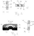
Fig. 1 is a perspective view of insert sleeves inserted into through holes of an osteosynthetic plate according to one exemplary embodiment of the present disclosure. -
Fig. 2a is a perspective view of insert sleeves inserted into through holes of an osteosynthetic plate according to another exemplary embodiment of the present disclosure. -
Fig. 2b is a top view of the osteosynthetic plate ofFig. 2a . -
Fig. 2c is a cross-sectional view of the osteosynthetic plate ofFig. 2b along Line A-A. -
Fig. 2d is a cross-sectional view of the osteosynthetic plate ofFig. 2b along Line B-B. -
Fig. 3a is a fragmentary view of an insert sleeve inserted into a through hole of an osteosynthetic plate according to another exemplary embodiment of the present disclosure. -
Fig. 3b is a cross-sectional view of the osteosynthetic plate ofFig. 3a similar toFig. 2c . -
Fig. 4 shows top views of two insert sleeves according to other exemplary embodiments of the present disclosure. - Corresponding reference characters indicate corresponding parts throughout the several views. The exemplifications set out herein illustrate exemplary embodiments of the disclosure, and such exemplifications are not to be construed as limiting the scope of the disclosure in any manner.
- Referring to
Fig. 1 ,osteosynthetic plate 11 is shown and forms an elongate body includingproximal side 13 and distal side 15 (cf.Figs. 2c, 2d ). Theosteosynthetic plate 11 may be used in treatment of bone fractures, for example. Theosteosynthetic plate 11 includes multiple throughholes 17 arranged in row along alongitudinal axis 12 of the elongate osteosynthetic plate 11 (cf.Fig. 2b ) to holdbone screws 25 for fastening theosteosynthetic plate 11 to the bone or bone fractures, respectively. - Insert
sleeves 19 are inserted into the through holes 17. Theinsert sleeves 19 may be made of a plastic material such as a polymer or an alloy, for example. Each of theinsert sleeves 19 is formed as a circular cylinder and is mainly comprised of a body 21 (cf.Figs. 2c, 2d ) that includes a central throughhole 23 for uniaxially receiving thebone screw 25 as well asmultiple recesses 27 or cut-outs arranged in circular manner around the central throughhole 23 that defines anaxial direction 29. Theaxial direction 29 is common to throughhole 23 of theinsert sleeve 19, throughhole 17 of theosteosynthetic plate 11, andbone screw 25. Each of therecesses 27 completely penetrates thebody 21 all the way from theproximal side 13 to thedistal side 15 and is confined between radially inner and outer portions of thebody 21. - The
multiple recesses 27 of eachinsert sleeve 19 comprise two elongated curved recesses 27' arranged opposite to each other with respect to theaxial direction 29 and along a first transverse direction 31 (cf.Fig. 2b ), and two pairs of radially extendingrecesses 27" arranged opposite to each other along a second transverse direction 33 (cf.Fig. 2b ) perpendicular to the firsttransverse direction 31. The first andsecond directions axial direction 29 of theinsert sleeve 19. By omitting material from thebody 21 to form therecesses 27 the in-plane stiffness of theinsert sleeve 19 is reduced. In particular, the transverse stiffness is lower in the firsttransverse direction 31 than in the secondtransverse direction 33 due to the arrangement and the shape of therecesses 27. At least one (not-shown) guide feature providing also a security against rotation relative to theaxial direction 29 can be included in theinsert sleeve 19 in order to ensure that a correct positioning of theinsert sleeve 19 within the throughhole 17 of theimplant 11 is brought about. Thus, the firsttransverse direction 31 of theinsert sleeve 19 can be selected in parallel to thelongitudinal axis 12 of theimplant 11. - The reduced stiffness of the
insert sleeves 19 leads to a corresponding reduced stiffness of theosteosynthetic plate 11 and osteosynthetic plate system, respectively. Thus, the present osteosynthetic plate system beneficially assists in stimulating the bone to remodel itself over time. - Referring to
Fig. 2a , each of therecesses 27 of eachinsert sleeve 19 is fully filled with afiller material 41. The filler material may be made of a polymer such as polyether ether ketone (PEEK), for example. Thefiller material 41 has a modulus of elasticity which is smaller than the modulus of elasticity of thebody 21 but may in general also be higher. The transverse stiffness of theinsert sleeve 19 according toFig. 2a is higher than the transverse stiffness of theinsert sleeve 19 according toFig. 1 . In a particular embodiment, thefiller material 41 is bioresorbable. This results in a change of the transverse stiffness of theinsert sleeve 19 over time. In particular, the transverse stiffness decreases. Thus, the load that has to be borne by the bone increases over time to further stimulate the bone to remodel itself. - As can be seen in
Figs. 2c and 2d , theinsert sleeve 19 is pressed into the throughhole 17 of theosteosynthetic plate 11 to form a snap-fit connection. In general, theinsert sleeves 19 may also be threadable into the throughholes 17 of theosteosynthetic plate 11. - A diameter of the through
hole 23 of eachinsert sleeve 19 is larger in a proximal section of theinsert sleeve 19 than in a distal section to form animpression 35. The diameter of the throughhole 23 is such that a shaft 37 (cf.Fig. 2a ) of thebone screw 25 may pass even through the smaller distal part of the throughhole 23 whereas a head 39 (cf.Fig. 2a ) of thebone screw 25 may not pass through the smaller distal part of the throughhole 23 and is seatably received in theimpression 35. - Referring to
Figs. 3a and 3b , thebody 21 of eachinsert sleeve 19 is provided with abushing 43 at its inner annular surface, wherein thebushing 43 forms the throughhole 23 of theinsert sleeve 19. Thebushing 43 may be provided to improve the tribological properties of the interface between therespective bone screw 25 and therespective insert sleeve 19. - The
insert sleeves 19 may have a shape or an outer shape, respectively, which differs from a circular cylinder. As shown inFig. 4 , theinsert sleeves 19 may also have an oval shape, for example, wherein the long axis of the oval may either coincide with the first transverse direction 31 (left drawing) or the second transverse direction 33 (right drawing). - The invention comprises the following individual aspects which - despite the fact that they contain reference numbers are only intended to refer to the exemplary embodiments shown in the drawings as examples - are not limited to these exemplary embodiments.
- An
insert sleeve 19 designed for being inserted into a throughhole 17 of animplant 11, comprises abody 21 with a throughhole 23 defining anaxial direction 29 for receiving abone anchoring element 25, in particular a bone screw, saidbody 21 being made of a material having a first modulus of elasticity and includingmultiple recesses 27 arranged in circumferential direction around said throughhole 23 of saidinsert sleeve 19 for reducing a stiffness of saidinsert sleeve 19 in a direction transverse 31, 33 to saidaxial direction 29, wherein at least one of said recesses 27 is filled with afiller material 41 having a second modulus of elasticity different from said first modulus of elasticity.
Saidmultiple recesses 27 may be configured and arranged to increase the flexibility of saidinsert sleeve 19.
Said recesses 27 may be arranged and/or shaped such that said transverse stiffness is lower in a firsttransverse direction 31 than in a secondtransverse direction 33.
Said second modulus of elasticity may be smaller than said first modulus of elasticity.
Saidfiller material 41 may be bioresorbable.
Said recesses 27 may open out to at least one axial and/or annual face of saidinsert sleeve 19.
At least one of said recesses 27 may completely penetrate saidbody 21 inaxial direction 29.
Saidinsert sleeve 19 may be a circular cylinder.
Said recesses 27 may be arranged and/or shaped symmetrically with respect to a plane defined by saidaxial direction 29 and said firsttransverse direction 31 and/or with respect to a plane defined by saidaxial direction 29 and said secondtransverse direction 33.
At least one of said recesses 27 may be of oblong curved shape extending in circumferential direction.
At least one of said recesses 27 may be a slit extending in radial direction. At aproximal side 13 of saidinsert sleeve 19, a diameter of said throughhole 23 of saidinsert sleeve 19 may be enlarged to form animpression 35 for receiving ahead 39 of saidbone anchoring element 25.
Said insert sleeve may be configured such that at least part of ashaft 37 of saidbone anchoring element 25 is feedable through said throughhole 23 of saidinsert sleeve 19, whereas ahead 39 of saidbone anchoring element 25 is receivable in animpression 35 formed at aproximal side 13 of saidinsert sleeve 19.
Saidinsert sleeve 19 may be configured such that said bone anchoring element is uniaxially receivable in said insert sleeve and/or such that said insert sleeve is uniaxially receivable in said through hole of saidimplant 11.
Saidinsert sleeve 19 may be provided with abushing 43 at an inner annular surface of saidbody 21.
Saidinsert sleeve 19 may comprise at least one feature providing a security against rotation relative to saidaxial direction 29 when inserted in saidtrough hole 17 of saidimplant 11.
Saidinsert sleeve 19 may comprise at least one guide feature configured such that saidinsert sleeve 19 may be received in saidtrough hole 17 of saidimplant 11 only in at least one pre-defined discrete rotational orientation relative to saidaxial direction 29, in particular in multiple pre-defined discrete rotational orientations.
Saidinsert sleeve 19 may comprise at least one axial stop that is configured to provide an abutment when inserting saidinsert sleeve 19 in said throughhole 17 of saidimplant 11.
In a set of insert sleeves in accordance with any of the preceding aspects, groups ofinsert sleeves 19 may differ from each other in arrangement and/or shape of said recesses.
An implant system comprises animplant 11, in particular a bone fixing apparatus such as an orthopedic plate, including multiple throughholes 17, in particular bores, at least oneinsert sleeve 19 in accordance with any of the preceding aspects designed for being inserted into one of said throughholes 17, and optionally multiplebone anchoring elements 25. At least oneinsert sleeve 19 may be arranged in one of said throughholes 17 of saidimplant 11, in particular is configured to be uniaxially received in one of said throughholes 17 of saidimplant 11.
Theimplant 11 may comprisemultiple insert sleeves 19. - While the prosthesis design shown and described above is an osteosynthetic plate system, it is contemplated that other implants such as acetabular cups in hip replacements or vertebral plates may also be made in accordance with the present disclosure.
- While this disclosure has been described as having exemplary designs, the present disclosure can be further modified within the spirit and scope of this disclosure. This application is therefore intended to cover any variations, uses, or adaptations of the disclosure using its general principles. Further, this application is intended to cover such departures from the present disclosure as come within known or customary practice in the art to which this disclosure pertains and which fall within the limits of the appended claims.
-
11 osteosynthetic plate 12 longitudinal axis 13 proximal side 15 distal side 17 through holes 19 insert sleeve 21 body 23 through hole 25 bone screw 27 recess 29 axial direction 31 first transverse direction 33 second transverse direction 35 impression 37 shaft 39 head 41 filler material 43 bushing
Claims (15)
- An insert sleeve (19) designed for being inserted into a through hole (17) of an implant (11), comprising a body (21) with a through hole (23) defining an axial direction (29) for receiving a bone anchoring element (25), in particular a bone screw, said body (21) being made of a material having a first modulus of elasticity and including multiple recesses (27) arranged in circumferential direction around said through hole (23) of said insert sleeve (19).
- The insert of claim 1, wherein the recesses (27) are arranged for reducing a transverse stiffness of the insert sleeve (19) and/or of the implant (11), in particular in a direction at least essentially perpendicular to the axial direction of the through hole.
- The insert of claim 1 or claim 2, wherein said multiple recesses (27) are configured and arranged to increase the flexibility of said insert sleeve (19).
- The insert of any of claims 1 to 3, wherein said recesses (27) are arranged and/or shaped such that said transverse stiffness is lower in a first transverse direction (31) than in a second transverse direction (33).
- The insert of any of claims 1 to 4, wherein the transverse stiffness of the insert sleeve (19) is time-dependent, in particular decreases over time.
- The insert of any of claims 1 to 5, wherein at least one of said recesses (27) is filled with a filler material (41) having a second modulus of elasticity different from said first modulus of elasticity, wherein in particular said second modulus of elasticity is smaller than said first modulus of elasticity.
- The insert of claim 6, wherein said filler material (41) is bioresorbable.
- The insert of any of claims 1 to 7, wherein the insert sleeve (19) has a non-circular shape, in particular an oval shape or a rectangular shape, and/or
wherein at least one of said recesses (27) is of oblong curved shape extending in circumferential direction, and/or
wherein at least one of said recesses (27) is a slit extending in radial direction. - The insert of any of claims 1 to 8, wherein at a proximal side (13) of said insert sleeve (19), a diameter of said through hole (23) of said insert sleeve (19) is enlarged to form an impression (35) for receiving a head (39) of said bone anchoring element (25), and/or
wherein said insert sleeve (19) is configured such that at least part of a shaft (37) of said bone anchoring element (25) is feedable through said through hole (23) of said insert sleeve (19), whereas a head (39) of said bone anchoring element (25) is receivable in an impression (35) formed at a proximal side (13) of said insert sleeve (19). - The insert of any of claims 1 to 9, wherein said insert sleeve (19) is provided with a bushing (43) at an inner annular surface of said body (21), and/or
wherein said insert sleeve (19) comprises at least one guide feature configured such that said insert sleeve (19) may be received in said trough hole (17) of said implant (11) only in at least one pre-defined discrete rotational orientation relative to said axial direction (29), in particular in multiple pre-defined discrete rotational orientations. - The insert of any of claims 1 to 10, wherein the insert sleeve (19) is adapted to allow a bone anchoring element (25), which is inserted through the through hole (23), to move relative to the body (21).
- An implant system comprising an implant (11), in particular a bone fixing apparatus such as an orthopedic plate, including multiple through holes (17), in particular bores, at least one insert sleeve (19) in accordance with any of claims 1 to 11 designed for being inserted into one of said through holes (17), and optionally multiple bone anchoring elements (25).
- The system of claim 12, wherein the insert sleeve (19) is adapted to stimulate remodeling of a fractured bone when the implant is attached to that bone.
- The system of claim 12 or claim 13, wherein the insert sleeve (19) is adapted to allow a bone anchoring element (25) and/or a bone or bone fragment affixed to a bone anchoring element (25) being inserted through the through hole (23), to move relative to the implant (11).
- An implant system in accordance with any of claims 12 to 14, wherein said implant (11) comprises multiple insert sleeves (19).
Applications Claiming Priority (3)
| Application Number | Priority Date | Filing Date | Title |
|---|---|---|---|
| EP13163522.9A EP2789303A1 (en) | 2013-04-12 | 2013-04-12 | Implantable insert sleeve |
| PCT/EP2014/057434 WO2014167117A1 (en) | 2013-04-12 | 2014-04-11 | Implantable insert sleeve |
| EP14716846.2A EP2948081B1 (en) | 2013-04-12 | 2014-04-11 | Implantable insert sleeve |
Related Parent Applications (1)
| Application Number | Title | Priority Date | Filing Date |
|---|---|---|---|
| EP14716846.2A Division EP2948081B1 (en) | 2013-04-12 | 2014-04-11 | Implantable insert sleeve |
Publications (2)
| Publication Number | Publication Date |
|---|---|
| EP3146922A1 true EP3146922A1 (en) | 2017-03-29 |
| EP3146922B1 EP3146922B1 (en) | 2019-10-23 |
Family
ID=48092788
Family Applications (3)
| Application Number | Title | Priority Date | Filing Date |
|---|---|---|---|
| EP13163522.9A Withdrawn EP2789303A1 (en) | 2013-04-12 | 2013-04-12 | Implantable insert sleeve |
| EP16198164.2A Active EP3146922B1 (en) | 2013-04-12 | 2014-04-11 | Implantable insert sleeve |
| EP14716846.2A Active EP2948081B1 (en) | 2013-04-12 | 2014-04-11 | Implantable insert sleeve |
Family Applications Before (1)
| Application Number | Title | Priority Date | Filing Date |
|---|---|---|---|
| EP13163522.9A Withdrawn EP2789303A1 (en) | 2013-04-12 | 2013-04-12 | Implantable insert sleeve |
Family Applications After (1)
| Application Number | Title | Priority Date | Filing Date |
|---|---|---|---|
| EP14716846.2A Active EP2948081B1 (en) | 2013-04-12 | 2014-04-11 | Implantable insert sleeve |
Country Status (3)
| Country | Link |
|---|---|
| US (1) | US9642659B2 (en) |
| EP (3) | EP2789303A1 (en) |
| WO (1) | WO2014167117A1 (en) |
Families Citing this family (9)
| Publication number | Priority date | Publication date | Assignee | Title |
|---|---|---|---|---|
| US9078701B2 (en) * | 2009-11-09 | 2015-07-14 | Centinel Spine, Inc. | System and method for stabilizing a posterior fusion over motion segments |
| AU2011270934B2 (en) | 2010-06-23 | 2014-09-11 | Zimmer, Inc | Flexible plate fixation of bone fractures |
| US8790379B2 (en) | 2010-06-23 | 2014-07-29 | Zimmer, Inc. | Flexible plate fixation of bone fractures |
| US9295508B2 (en) | 2012-02-03 | 2016-03-29 | Zimmer, Inc. | Bone plate for elastic osteosynthesis |
| CN104814783B (en) * | 2015-04-23 | 2018-02-27 | 济南大学 | Locked pressurized bone plate |
| US10966765B2 (en) * | 2015-09-05 | 2021-04-06 | Life Spine, Inc. | Orthopedic implants with variable angle bone screw locking |
| CA3149638A1 (en) * | 2019-08-06 | 2021-02-11 | Paragon 28, Inc. | Dynamic bone plate and method of use |
| US11324538B2 (en) | 2019-12-04 | 2022-05-10 | Biomet Manufacturing, Llc | Active bone plate |
| WO2022241199A1 (en) * | 2021-05-14 | 2022-11-17 | B-Plate Inc. | Bone fixation system |
Citations (5)
| Publication number | Priority date | Publication date | Assignee | Title |
|---|---|---|---|---|
| US20010014807A1 (en) * | 1997-08-04 | 2001-08-16 | Erik J. Wagner | System and method for stabilizing the human spine with a bone plate |
| US20040220570A1 (en) * | 1998-05-19 | 2004-11-04 | Synthes (Usa) | Osteosynthetic implant with an embedded hinge joint |
| US20120016365A1 (en) * | 2000-01-06 | 2012-01-19 | Jim Freid | Bone plate system and method for spine stabilization |
| US20120303071A1 (en) * | 2011-05-27 | 2012-11-29 | Michael Black | Securing Fasteners |
| US20120310289A1 (en) * | 2010-06-23 | 2012-12-06 | Apex Biomedical Company Llc | Flexible plate fixation of bone fractures |
Family Cites Families (1)
| Publication number | Priority date | Publication date | Assignee | Title |
|---|---|---|---|---|
| AU2011270934B2 (en) * | 2010-06-23 | 2014-09-11 | Zimmer, Inc | Flexible plate fixation of bone fractures |
-
2013
- 2013-04-12 EP EP13163522.9A patent/EP2789303A1/en not_active Withdrawn
-
2014
- 2014-04-11 US US14/783,598 patent/US9642659B2/en not_active Expired - Fee Related
- 2014-04-11 EP EP16198164.2A patent/EP3146922B1/en active Active
- 2014-04-11 EP EP14716846.2A patent/EP2948081B1/en active Active
- 2014-04-11 WO PCT/EP2014/057434 patent/WO2014167117A1/en not_active Ceased
Patent Citations (5)
| Publication number | Priority date | Publication date | Assignee | Title |
|---|---|---|---|---|
| US20010014807A1 (en) * | 1997-08-04 | 2001-08-16 | Erik J. Wagner | System and method for stabilizing the human spine with a bone plate |
| US20040220570A1 (en) * | 1998-05-19 | 2004-11-04 | Synthes (Usa) | Osteosynthetic implant with an embedded hinge joint |
| US20120016365A1 (en) * | 2000-01-06 | 2012-01-19 | Jim Freid | Bone plate system and method for spine stabilization |
| US20120310289A1 (en) * | 2010-06-23 | 2012-12-06 | Apex Biomedical Company Llc | Flexible plate fixation of bone fractures |
| US20120303071A1 (en) * | 2011-05-27 | 2012-11-29 | Michael Black | Securing Fasteners |
Also Published As
| Publication number | Publication date |
|---|---|
| EP2948081B1 (en) | 2016-11-23 |
| US20160081729A1 (en) | 2016-03-24 |
| WO2014167117A1 (en) | 2014-10-16 |
| EP3146922B1 (en) | 2019-10-23 |
| US9642659B2 (en) | 2017-05-09 |
| EP2789303A1 (en) | 2014-10-15 |
| EP2948081A1 (en) | 2015-12-02 |
Similar Documents
| Publication | Publication Date | Title |
|---|---|---|
| US9642659B2 (en) | Implantable insert sleeve | |
| AU2019250124B2 (en) | Metacarpal neck plate | |
| US8403966B2 (en) | Clavicle plate and screws | |
| US8444679B2 (en) | Clavicle plate and screws | |
| US20190150999A1 (en) | Calcaneal bone plate targeting guide | |
| KR102211256B1 (en) | Bump cut on hole edge | |
| US20130261622A1 (en) | Implant for proximal fractures of long bones | |
| AU2019204554B2 (en) | Phalangeal head plate | |
| US20150250507A1 (en) | Components for bone fixation devices | |
| CN107223040B (en) | Intramedullary fixation devices and systems for hip and femoral fracture surgery | |
| AU2015284639B2 (en) | Variable angle locking rotation correction plate | |
| CN106572871A (en) | Implant and surgical kit for holding bone bodies of a patient in position with respect to one another | |
| EP3386406A1 (en) | Composite implant trial | |
| CA2836443C (en) | Modular lag screw |
Legal Events
| Date | Code | Title | Description |
|---|---|---|---|
| PUAI | Public reference made under article 153(3) epc to a published international application that has entered the european phase |
Free format text: ORIGINAL CODE: 0009012 |
|
| STAA | Information on the status of an ep patent application or granted ep patent |
Free format text: STATUS: THE APPLICATION HAS BEEN PUBLISHED |
|
| AC | Divisional application: reference to earlier application |
Ref document number: 2948081 Country of ref document: EP Kind code of ref document: P |
|
| AK | Designated contracting states |
Kind code of ref document: A1 Designated state(s): AL AT BE BG CH CY CZ DE DK EE ES FI FR GB GR HR HU IE IS IT LI LT LU LV MC MK MT NL NO PL PT RO RS SE SI SK SM TR |
|
| STAA | Information on the status of an ep patent application or granted ep patent |
Free format text: STATUS: REQUEST FOR EXAMINATION WAS MADE |
|
| 17P | Request for examination filed |
Effective date: 20170926 |
|
| RBV | Designated contracting states (corrected) |
Designated state(s): AL AT BE BG CH CY CZ DE DK EE ES FI FR GB GR HR HU IE IS IT LI LT LU LV MC MK MT NL NO PL PT RO RS SE SI SK SM TR |
|
| GRAP | Despatch of communication of intention to grant a patent |
Free format text: ORIGINAL CODE: EPIDOSNIGR1 |
|
| STAA | Information on the status of an ep patent application or granted ep patent |
Free format text: STATUS: GRANT OF PATENT IS INTENDED |
|
| INTG | Intention to grant announced |
Effective date: 20190516 |
|
| GRAS | Grant fee paid |
Free format text: ORIGINAL CODE: EPIDOSNIGR3 |
|
| GRAA | (expected) grant |
Free format text: ORIGINAL CODE: 0009210 |
|
| STAA | Information on the status of an ep patent application or granted ep patent |
Free format text: STATUS: THE PATENT HAS BEEN GRANTED |
|
| AC | Divisional application: reference to earlier application |
Ref document number: 2948081 Country of ref document: EP Kind code of ref document: P |
|
| AK | Designated contracting states |
Kind code of ref document: B1 Designated state(s): AL AT BE BG CH CY CZ DE DK EE ES FI FR GB GR HR HU IE IS IT LI LT LU LV MC MK MT NL NO PL PT RO RS SE SI SK SM TR |
|
| REG | Reference to a national code |
Ref country code: GB Ref legal event code: FG4D |
|
| REG | Reference to a national code |
Ref country code: CH Ref legal event code: EP Ref country code: CH Ref legal event code: NV Representative=s name: DR. GRAF AND PARTNER AG INTELLECTUAL PROPERTY, CH |
|
| REG | Reference to a national code |
Ref country code: IE Ref legal event code: FG4D |
|
| REG | Reference to a national code |
Ref country code: DE Ref legal event code: R096 Ref document number: 602014055800 Country of ref document: DE |
|
| REG | Reference to a national code |
Ref country code: AT Ref legal event code: REF Ref document number: 1192784 Country of ref document: AT Kind code of ref document: T Effective date: 20191115 |
|
| REG | Reference to a national code |
Ref country code: NL Ref legal event code: MP Effective date: 20191023 |
|
| REG | Reference to a national code |
Ref country code: LT Ref legal event code: MG4D |
|
| PG25 | Lapsed in a contracting state [announced via postgrant information from national office to epo] |
Ref country code: PT Free format text: LAPSE BECAUSE OF FAILURE TO SUBMIT A TRANSLATION OF THE DESCRIPTION OR TO PAY THE FEE WITHIN THE PRESCRIBED TIME-LIMIT Effective date: 20200224 Ref country code: BG Free format text: LAPSE BECAUSE OF FAILURE TO SUBMIT A TRANSLATION OF THE DESCRIPTION OR TO PAY THE FEE WITHIN THE PRESCRIBED TIME-LIMIT Effective date: 20200123 Ref country code: FI Free format text: LAPSE BECAUSE OF FAILURE TO SUBMIT A TRANSLATION OF THE DESCRIPTION OR TO PAY THE FEE WITHIN THE PRESCRIBED TIME-LIMIT Effective date: 20191023 Ref country code: GR Free format text: LAPSE BECAUSE OF FAILURE TO SUBMIT A TRANSLATION OF THE DESCRIPTION OR TO PAY THE FEE WITHIN THE PRESCRIBED TIME-LIMIT Effective date: 20200124 Ref country code: PL Free format text: LAPSE BECAUSE OF FAILURE TO SUBMIT A TRANSLATION OF THE DESCRIPTION OR TO PAY THE FEE WITHIN THE PRESCRIBED TIME-LIMIT Effective date: 20191023 Ref country code: NO Free format text: LAPSE BECAUSE OF FAILURE TO SUBMIT A TRANSLATION OF THE DESCRIPTION OR TO PAY THE FEE WITHIN THE PRESCRIBED TIME-LIMIT Effective date: 20200123 Ref country code: NL Free format text: LAPSE BECAUSE OF FAILURE TO SUBMIT A TRANSLATION OF THE DESCRIPTION OR TO PAY THE FEE WITHIN THE PRESCRIBED TIME-LIMIT Effective date: 20191023 Ref country code: LV Free format text: LAPSE BECAUSE OF FAILURE TO SUBMIT A TRANSLATION OF THE DESCRIPTION OR TO PAY THE FEE WITHIN THE PRESCRIBED TIME-LIMIT Effective date: 20191023 Ref country code: SE Free format text: LAPSE BECAUSE OF FAILURE TO SUBMIT A TRANSLATION OF THE DESCRIPTION OR TO PAY THE FEE WITHIN THE PRESCRIBED TIME-LIMIT Effective date: 20191023 Ref country code: LT Free format text: LAPSE BECAUSE OF FAILURE TO SUBMIT A TRANSLATION OF THE DESCRIPTION OR TO PAY THE FEE WITHIN THE PRESCRIBED TIME-LIMIT Effective date: 20191023 |
|
| PG25 | Lapsed in a contracting state [announced via postgrant information from national office to epo] |
Ref country code: IS Free format text: LAPSE BECAUSE OF FAILURE TO SUBMIT A TRANSLATION OF THE DESCRIPTION OR TO PAY THE FEE WITHIN THE PRESCRIBED TIME-LIMIT Effective date: 20200224 Ref country code: HR Free format text: LAPSE BECAUSE OF FAILURE TO SUBMIT A TRANSLATION OF THE DESCRIPTION OR TO PAY THE FEE WITHIN THE PRESCRIBED TIME-LIMIT Effective date: 20191023 Ref country code: RS Free format text: LAPSE BECAUSE OF FAILURE TO SUBMIT A TRANSLATION OF THE DESCRIPTION OR TO PAY THE FEE WITHIN THE PRESCRIBED TIME-LIMIT Effective date: 20191023 |
|
| PG25 | Lapsed in a contracting state [announced via postgrant information from national office to epo] |
Ref country code: AL Free format text: LAPSE BECAUSE OF FAILURE TO SUBMIT A TRANSLATION OF THE DESCRIPTION OR TO PAY THE FEE WITHIN THE PRESCRIBED TIME-LIMIT Effective date: 20191023 |
|
| REG | Reference to a national code |
Ref country code: DE Ref legal event code: R097 Ref document number: 602014055800 Country of ref document: DE |
|
| PG2D | Information on lapse in contracting state deleted |
Ref country code: IS |
|
| PG25 | Lapsed in a contracting state [announced via postgrant information from national office to epo] |
Ref country code: EE Free format text: LAPSE BECAUSE OF FAILURE TO SUBMIT A TRANSLATION OF THE DESCRIPTION OR TO PAY THE FEE WITHIN THE PRESCRIBED TIME-LIMIT Effective date: 20191023 Ref country code: DK Free format text: LAPSE BECAUSE OF FAILURE TO SUBMIT A TRANSLATION OF THE DESCRIPTION OR TO PAY THE FEE WITHIN THE PRESCRIBED TIME-LIMIT Effective date: 20191023 Ref country code: CZ Free format text: LAPSE BECAUSE OF FAILURE TO SUBMIT A TRANSLATION OF THE DESCRIPTION OR TO PAY THE FEE WITHIN THE PRESCRIBED TIME-LIMIT Effective date: 20191023 Ref country code: RO Free format text: LAPSE BECAUSE OF FAILURE TO SUBMIT A TRANSLATION OF THE DESCRIPTION OR TO PAY THE FEE WITHIN THE PRESCRIBED TIME-LIMIT Effective date: 20191023 Ref country code: ES Free format text: LAPSE BECAUSE OF FAILURE TO SUBMIT A TRANSLATION OF THE DESCRIPTION OR TO PAY THE FEE WITHIN THE PRESCRIBED TIME-LIMIT Effective date: 20191023 Ref country code: IS Free format text: LAPSE BECAUSE OF FAILURE TO SUBMIT A TRANSLATION OF THE DESCRIPTION OR TO PAY THE FEE WITHIN THE PRESCRIBED TIME-LIMIT Effective date: 20200223 |
|
| REG | Reference to a national code |
Ref country code: AT Ref legal event code: MK05 Ref document number: 1192784 Country of ref document: AT Kind code of ref document: T Effective date: 20191023 |
|
| PLBE | No opposition filed within time limit |
Free format text: ORIGINAL CODE: 0009261 |
|
| STAA | Information on the status of an ep patent application or granted ep patent |
Free format text: STATUS: NO OPPOSITION FILED WITHIN TIME LIMIT |
|
| PG25 | Lapsed in a contracting state [announced via postgrant information from national office to epo] |
Ref country code: SM Free format text: LAPSE BECAUSE OF FAILURE TO SUBMIT A TRANSLATION OF THE DESCRIPTION OR TO PAY THE FEE WITHIN THE PRESCRIBED TIME-LIMIT Effective date: 20191023 Ref country code: IT Free format text: LAPSE BECAUSE OF FAILURE TO SUBMIT A TRANSLATION OF THE DESCRIPTION OR TO PAY THE FEE WITHIN THE PRESCRIBED TIME-LIMIT Effective date: 20191023 Ref country code: SK Free format text: LAPSE BECAUSE OF FAILURE TO SUBMIT A TRANSLATION OF THE DESCRIPTION OR TO PAY THE FEE WITHIN THE PRESCRIBED TIME-LIMIT Effective date: 20191023 |
|
| 26N | No opposition filed |
Effective date: 20200724 |
|
| PG25 | Lapsed in a contracting state [announced via postgrant information from national office to epo] |
Ref country code: MC Free format text: LAPSE BECAUSE OF FAILURE TO SUBMIT A TRANSLATION OF THE DESCRIPTION OR TO PAY THE FEE WITHIN THE PRESCRIBED TIME-LIMIT Effective date: 20191023 Ref country code: AT Free format text: LAPSE BECAUSE OF FAILURE TO SUBMIT A TRANSLATION OF THE DESCRIPTION OR TO PAY THE FEE WITHIN THE PRESCRIBED TIME-LIMIT Effective date: 20191023 Ref country code: SI Free format text: LAPSE BECAUSE OF FAILURE TO SUBMIT A TRANSLATION OF THE DESCRIPTION OR TO PAY THE FEE WITHIN THE PRESCRIBED TIME-LIMIT Effective date: 20191023 |
|
| PG25 | Lapsed in a contracting state [announced via postgrant information from national office to epo] |
Ref country code: LU Free format text: LAPSE BECAUSE OF NON-PAYMENT OF DUE FEES Effective date: 20200411 |
|
| REG | Reference to a national code |
Ref country code: BE Ref legal event code: MM Effective date: 20200430 |
|
| PG25 | Lapsed in a contracting state [announced via postgrant information from national office to epo] |
Ref country code: BE Free format text: LAPSE BECAUSE OF NON-PAYMENT OF DUE FEES Effective date: 20200430 |
|
| PG25 | Lapsed in a contracting state [announced via postgrant information from national office to epo] |
Ref country code: IE Free format text: LAPSE BECAUSE OF NON-PAYMENT OF DUE FEES Effective date: 20200411 |
|
| PG25 | Lapsed in a contracting state [announced via postgrant information from national office to epo] |
Ref country code: TR Free format text: LAPSE BECAUSE OF FAILURE TO SUBMIT A TRANSLATION OF THE DESCRIPTION OR TO PAY THE FEE WITHIN THE PRESCRIBED TIME-LIMIT Effective date: 20191023 Ref country code: MT Free format text: LAPSE BECAUSE OF FAILURE TO SUBMIT A TRANSLATION OF THE DESCRIPTION OR TO PAY THE FEE WITHIN THE PRESCRIBED TIME-LIMIT Effective date: 20191023 Ref country code: CY Free format text: LAPSE BECAUSE OF FAILURE TO SUBMIT A TRANSLATION OF THE DESCRIPTION OR TO PAY THE FEE WITHIN THE PRESCRIBED TIME-LIMIT Effective date: 20191023 |
|
| PG25 | Lapsed in a contracting state [announced via postgrant information from national office to epo] |
Ref country code: MK Free format text: LAPSE BECAUSE OF FAILURE TO SUBMIT A TRANSLATION OF THE DESCRIPTION OR TO PAY THE FEE WITHIN THE PRESCRIBED TIME-LIMIT Effective date: 20191023 |
|
| P01 | Opt-out of the competence of the unified patent court (upc) registered |
Effective date: 20230525 |
|
| PGFP | Annual fee paid to national office [announced via postgrant information from national office to epo] |
Ref country code: FR Payment date: 20250314 Year of fee payment: 12 |
|
| PGFP | Annual fee paid to national office [announced via postgrant information from national office to epo] |
Ref country code: GB Payment date: 20250312 Year of fee payment: 12 |
|
| PGFP | Annual fee paid to national office [announced via postgrant information from national office to epo] |
Ref country code: DE Payment date: 20250313 Year of fee payment: 12 |
|
| PGFP | Annual fee paid to national office [announced via postgrant information from national office to epo] |
Ref country code: CH Payment date: 20250501 Year of fee payment: 12 |