EP3146903B1 - Occlusion device for closing an apical hole in the heart wall - Google Patents
Occlusion device for closing an apical hole in the heart wall Download PDFInfo
- Publication number
- EP3146903B1 EP3146903B1 EP15186551.6A EP15186551A EP3146903B1 EP 3146903 B1 EP3146903 B1 EP 3146903B1 EP 15186551 A EP15186551 A EP 15186551A EP 3146903 B1 EP3146903 B1 EP 3146903B1
- Authority
- EP
- European Patent Office
- Prior art keywords
- occlusion device
- apical hole
- disks
- heart wall
- apical
- Prior art date
- Legal status (The legal status is an assumption and is not a legal conclusion. Google has not performed a legal analysis and makes no representation as to the accuracy of the status listed.)
- Not-in-force
Links
- 230000017531 blood circulation Effects 0.000 claims description 5
- 229910052751 metal Inorganic materials 0.000 claims description 5
- 239000002184 metal Substances 0.000 claims description 5
- 230000002401 inhibitory effect Effects 0.000 claims description 4
- 230000002093 peripheral effect Effects 0.000 claims description 4
- 229910001285 shape-memory alloy Inorganic materials 0.000 claims description 3
- 239000000956 alloy Substances 0.000 claims description 2
- 238000000034 method Methods 0.000 description 13
- 210000004165 myocardium Anatomy 0.000 description 5
- 230000000747 cardiac effect Effects 0.000 description 4
- 238000001356 surgical procedure Methods 0.000 description 4
- 230000002861 ventricular Effects 0.000 description 4
- 238000010276 construction Methods 0.000 description 3
- 239000004744 fabric Substances 0.000 description 3
- 239000000463 material Substances 0.000 description 3
- 208000035478 Interatrial communication Diseases 0.000 description 2
- 208000013914 atrial heart septal defect Diseases 0.000 description 2
- 206010003664 atrial septal defect Diseases 0.000 description 2
- 230000000740 bleeding effect Effects 0.000 description 2
- 238000007789 sealing Methods 0.000 description 2
- 244000208734 Pisonia aculeata Species 0.000 description 1
- 102000007327 Protamines Human genes 0.000 description 1
- 108010007568 Protamines Proteins 0.000 description 1
- 230000001154 acute effect Effects 0.000 description 1
- 210000003484 anatomy Anatomy 0.000 description 1
- 230000010100 anticoagulation Effects 0.000 description 1
- 210000001765 aortic valve Anatomy 0.000 description 1
- 210000003157 atrial septum Anatomy 0.000 description 1
- 239000008280 blood Substances 0.000 description 1
- 210000004369 blood Anatomy 0.000 description 1
- 238000007675 cardiac surgery Methods 0.000 description 1
- 230000002526 effect on cardiovascular system Effects 0.000 description 1
- 230000000694 effects Effects 0.000 description 1
- 230000035876 healing Effects 0.000 description 1
- 208000025339 heart septal defect Diseases 0.000 description 1
- 210000003709 heart valve Anatomy 0.000 description 1
- 238000010438 heat treatment Methods 0.000 description 1
- 238000001802 infusion Methods 0.000 description 1
- 210000005240 left ventricle Anatomy 0.000 description 1
- 238000004519 manufacturing process Methods 0.000 description 1
- 229910001000 nickel titanium Inorganic materials 0.000 description 1
- 230000035515 penetration Effects 0.000 description 1
- 229940048914 protamine Drugs 0.000 description 1
- 238000011084 recovery Methods 0.000 description 1
- 239000003566 sealing material Substances 0.000 description 1
- 238000007493 shaping process Methods 0.000 description 1
Images
Classifications
-
- A—HUMAN NECESSITIES
- A61—MEDICAL OR VETERINARY SCIENCE; HYGIENE
- A61B—DIAGNOSIS; SURGERY; IDENTIFICATION
- A61B17/00—Surgical instruments, devices or methods
- A61B17/0057—Implements for plugging an opening in the wall of a hollow or tubular organ, e.g. for sealing a vessel puncture or closing a cardiac septal defect
-
- A—HUMAN NECESSITIES
- A61—MEDICAL OR VETERINARY SCIENCE; HYGIENE
- A61B—DIAGNOSIS; SURGERY; IDENTIFICATION
- A61B17/00—Surgical instruments, devices or methods
- A61B17/12—Surgical instruments, devices or methods for ligaturing or otherwise compressing tubular parts of the body, e.g. blood vessels or umbilical cord
- A61B17/12022—Occluding by internal devices, e.g. balloons or releasable wires
- A61B17/12099—Occluding by internal devices, e.g. balloons or releasable wires characterised by the location of the occluder
- A61B17/12122—Occluding by internal devices, e.g. balloons or releasable wires characterised by the location of the occluder within the heart
-
- A—HUMAN NECESSITIES
- A61—MEDICAL OR VETERINARY SCIENCE; HYGIENE
- A61B—DIAGNOSIS; SURGERY; IDENTIFICATION
- A61B17/00—Surgical instruments, devices or methods
- A61B17/12—Surgical instruments, devices or methods for ligaturing or otherwise compressing tubular parts of the body, e.g. blood vessels or umbilical cord
- A61B17/12022—Occluding by internal devices, e.g. balloons or releasable wires
- A61B17/12131—Occluding by internal devices, e.g. balloons or releasable wires characterised by the type of occluding device
- A61B17/12168—Occluding by internal devices, e.g. balloons or releasable wires characterised by the type of occluding device having a mesh structure
- A61B17/12172—Occluding by internal devices, e.g. balloons or releasable wires characterised by the type of occluding device having a mesh structure having a pre-set deployed three-dimensional shape
-
- A—HUMAN NECESSITIES
- A61—MEDICAL OR VETERINARY SCIENCE; HYGIENE
- A61B—DIAGNOSIS; SURGERY; IDENTIFICATION
- A61B17/00—Surgical instruments, devices or methods
- A61B17/00234—Surgical instruments, devices or methods for minimally invasive surgery
- A61B2017/00238—Type of minimally invasive operation
- A61B2017/00243—Type of minimally invasive operation cardiac
-
- A—HUMAN NECESSITIES
- A61—MEDICAL OR VETERINARY SCIENCE; HYGIENE
- A61B—DIAGNOSIS; SURGERY; IDENTIFICATION
- A61B17/00—Surgical instruments, devices or methods
- A61B17/0057—Implements for plugging an opening in the wall of a hollow or tubular organ, e.g. for sealing a vessel puncture or closing a cardiac septal defect
- A61B2017/00575—Implements for plugging an opening in the wall of a hollow or tubular organ, e.g. for sealing a vessel puncture or closing a cardiac septal defect for closure at remote site, e.g. closing atrial septum defects
-
- A—HUMAN NECESSITIES
- A61—MEDICAL OR VETERINARY SCIENCE; HYGIENE
- A61B—DIAGNOSIS; SURGERY; IDENTIFICATION
- A61B17/00—Surgical instruments, devices or methods
- A61B17/0057—Implements for plugging an opening in the wall of a hollow or tubular organ, e.g. for sealing a vessel puncture or closing a cardiac septal defect
- A61B2017/00575—Implements for plugging an opening in the wall of a hollow or tubular organ, e.g. for sealing a vessel puncture or closing a cardiac septal defect for closure at remote site, e.g. closing atrial septum defects
- A61B2017/00592—Elastic or resilient implements
-
- A—HUMAN NECESSITIES
- A61—MEDICAL OR VETERINARY SCIENCE; HYGIENE
- A61B—DIAGNOSIS; SURGERY; IDENTIFICATION
- A61B17/00—Surgical instruments, devices or methods
- A61B17/0057—Implements for plugging an opening in the wall of a hollow or tubular organ, e.g. for sealing a vessel puncture or closing a cardiac septal defect
- A61B2017/00575—Implements for plugging an opening in the wall of a hollow or tubular organ, e.g. for sealing a vessel puncture or closing a cardiac septal defect for closure at remote site, e.g. closing atrial septum defects
- A61B2017/00597—Implements comprising a membrane
-
- A—HUMAN NECESSITIES
- A61—MEDICAL OR VETERINARY SCIENCE; HYGIENE
- A61B—DIAGNOSIS; SURGERY; IDENTIFICATION
- A61B17/00—Surgical instruments, devices or methods
- A61B17/0057—Implements for plugging an opening in the wall of a hollow or tubular organ, e.g. for sealing a vessel puncture or closing a cardiac septal defect
- A61B2017/00575—Implements for plugging an opening in the wall of a hollow or tubular organ, e.g. for sealing a vessel puncture or closing a cardiac septal defect for closure at remote site, e.g. closing atrial septum defects
- A61B2017/00606—Implements H-shaped in cross-section, i.e. with occluders on both sides of the opening
-
- A—HUMAN NECESSITIES
- A61—MEDICAL OR VETERINARY SCIENCE; HYGIENE
- A61B—DIAGNOSIS; SURGERY; IDENTIFICATION
- A61B17/00—Surgical instruments, devices or methods
- A61B17/0057—Implements for plugging an opening in the wall of a hollow or tubular organ, e.g. for sealing a vessel puncture or closing a cardiac septal defect
- A61B2017/00575—Implements for plugging an opening in the wall of a hollow or tubular organ, e.g. for sealing a vessel puncture or closing a cardiac septal defect for closure at remote site, e.g. closing atrial septum defects
- A61B2017/00615—Implements with an occluder on one side of the opening and holding means therefor on the other
-
- A—HUMAN NECESSITIES
- A61—MEDICAL OR VETERINARY SCIENCE; HYGIENE
- A61B—DIAGNOSIS; SURGERY; IDENTIFICATION
- A61B17/00—Surgical instruments, devices or methods
- A61B17/12—Surgical instruments, devices or methods for ligaturing or otherwise compressing tubular parts of the body, e.g. blood vessels or umbilical cord
- A61B17/12022—Occluding by internal devices, e.g. balloons or releasable wires
- A61B2017/1205—Introduction devices
- A61B2017/12054—Details concerning the detachment of the occluding device from the introduction device
- A61B2017/12095—Threaded connection
Definitions
- the present invention relates to an occlusion device for use in heart surgery procedures for the closure of punctures made in the cardiac wall.
- the apex of the heart refers to a lower portion of the heart, usually at the bottom part of the left ventricle.
- the thickness of the apex wall varies with each individual and may have a thickness of up to 18 mm.
- TAVR transapical aortic valve replacement
- Apical closure devices and procedures have been advanced over the past years since the introduction of TAVR surgery, as illustrated for example in the review article " Left Ventricular Apical Access and Closure for TAVR", by P. Vallabhajosyula and W. Y. Szeto, in Cardiac Interventions Today March/April 2013, page 45 .
- the conventional closing procedures include purse-string suturing or a mattress suturing technique.
- a known closure device of Apica Cardiovascular Ltd. (ACS system) consists of a spiral coil designed to be rotated into the myocardium tissue about the apical hole.
- a closure cap is provided for sealing the coil, which provides a working port for future interventions if needed.
- it is still necessary to penetrate cardio tissue surrounding the apical hole and there is some risk of the closure cap being dislodged from the coil.
- US Patent No. 2012/0253386 A1 discloses another closure device comprising a main cylindrical body which can be deployed in a delivery device. Once deployed, prongs extend away from the axis of the main body and serve as anchors into the tissue surrounding the apical hole. The main body can then be collapsed to facilitate closure of the apical puncture.
- the closure apparatus comprises a tissue attachment portion arranged on the forward and rearward end of a cylindrical main body.
- the attachment portion includes hooks at both the distal end and proximal end of the cylindrical main body, which engage in the myocardium tissue around the hole for securement of the device.
- the cylindrical main body collapses toward the center of the hole and a sealing material is disposed within the center of the device to promote a sealing effect.
- US 2009/0062841 A1 discloses a double-disk occlude for PDA treatment.
- the device in its relaxed, unstretched condition has two disks aligned in spaced relation and linked together by a central cylindrical segment.
- the length of the central segment may approximate the thickness of the atrial septum.
- the two disks may have an outer diameter sufficiently larger than the cavity opening to prevent dislodgement of the device.
- the larger diameter portions of the disks are arranged to face one another.
- the object of the present invention is to provide an improved apical occlusion device which requires little or no suturing or penetration of the myocardium and which is conveniently applied with a standard delivery device through the lumen of a catheter.
- an occlusion device is provided as defined in claim 1.
- the device comprises a first disk having a first enlarged diameter flange portion adapted to be placed proximate an exterior end of an apical hole in a patient's heart wall and a first shoulder portion adapted to be placed within the apical hole near the exterior end.
- a second disk having a second enlarged diameter flange portion adapted to be placed proximate an interior end of the apical hole in the patient's heart wall and a second shoulder portion adapted to be placed within the apical hole near the interior end.
- a central waist portion extends between the first and second disks along a center axis of the device, which is adapted to extend through the apical hole and connect the first and second disks, while urging the disks toward one another when in the mounted condition.
- the occlusion device is made of metal wire mesh comprising a plurality of metal strands made of a shape memory alloy material.
- the wires are preferably made of a nickel-titanium alloy.
- the first and second shoulder portions have respective inner faces which lie opposite one another in the direction of a center axis of the device, where each inner face is inwardly concaved to form a recess in the relaxed condition of the device.
- the central waist portion interconnects the inner faces of the first and second shoulder portions, both in the relaxed condition of the device and in the expanded condition when the device is mounted in the apical hole.
- the inner faces are pulled axially apart and the recessed faces take on a flatter shape, while the first and second shoulder portions become separated. In this expanded, mounted condition, the inner flatter faces are separated axially from one another and lie substantially parallel to one another.
- the recessed inner faces of the first and second shoulder portions urge the double-disk device back toward the relaxed condition where the first and second shoulder portions are closest to one another.
- the first and second shoulder portions are axially separated from one another, where the tension in the wire mesh of the inner faces is translated into a tension to bias the first and second disk portions back toward one another transmitted by the central waist portion.
- This structure allows the device to be flexed both axially and laterally such that it is capable of adjusting to the length and orientation of any given apical hole.
- Figures 1 and 2 illustrate a first embodiment of the present invention, where the occlusion device is depicted in the relaxed condition, where the metal mesh components made of shape memory alloy wires are at their relaxed position.
- a first disk 2 having an enlarged diameter flange portion 25, shown on the left, is adapted to be placed proximate an exterior end of the apical hole in the patient's heart wall. The exterior end is the end of the hole facing the outside of the heart wall.
- the first disk 2 further comprises a first shoulder portion 20 which is adapted to be placed within the apical hole near the exterior end.
- a second disk 3 has an enlarged diameter flange portion 35 which is adapted to be placed proximate an interior end of the apical hole, i.e. the end which is within the patient's heart.
- a second shoulder portion 30 is adapted to be placed within the hole near the interior end.
- the occluder further comprises a central waist portion 4 which extends between the first and second disk portions 2, 3 along a center axis A of the device.
- the central waist portion 4 is adapted to extend through the apical hole and connect the first and second shoulder portions 20, 30 of the disks.
- the first and second shoulder portions 20, 30 have respective inner faces 22, 32 which lie opposite one another in the direction of the center axis A.
- Each inner face 22, 32 is concaved inwardly within its corresponding shoulder portion 20, 30 by an angle ⁇ so as to form a recess in the relaxed condition as indicated.
- the angle ⁇ between the central waist 4 and the inner faces 22 and 32 may be adjusted so as to allow the axial extension of the occluder to increase or decrease to adapt to thickness of the heart wall.
- the first and second disks are drawn apart from one another (see Figures 4 and 5 and the discussion below), such that the central waist portion 4 pulls the recessed inner faces 22, 32 from the relaxed condition shown in Figure 1 to a mounted condition shown in Figures 5 and 6 where the previously recessed inner faces now become substantially flat surfaces.
- expanding the two disks to move apart axially during deployment is resisted by the mesh structure of the recessed inner faces 22, 32 of the shoulder portions.
- the first and second shoulder portions 20, 30 are urged to return to the relaxed condition through the tensile force generated by the memory material of mesh structure of the inner faces 22, 32.
- the central waist portion 4 comprises first and second side waist portions 21, 31 which are connected respectively to the inner faces 22, 32 of the first and second shoulder portions 20, 30 as shown in Figure 1 .
- the central waist portion 4 may be formed integrally as one piece with the entire occluder, which is fabricated in a heat shaping process of the shape memory mesh material.
- the waist portion 4 is highly contracted in comparison to the outer disk portions of the occluder and will typically have a diameter of about 2 mm.
- the overall length of the central waist portion 4 can be varied depending on the individual patient, but is at least 5 mm and generally in the range of 5 to 18 mm in length. Preferably the central waist portion is in the range of 5 to 12 mm.
- the side waist portions 21, 31 are provided as a generally tubular mesh sections which join integrally with the mesh of the inner faces 22, 32.
- each disk structure 2, 3 including the enlarged diameter flange portion 25, 35, the shoulder portion 20, 30 and the respective part 21 or 31 of the waist portion are all formed of a single piece of wire mesh in a heat treatment for shape memory production.
- the flange portions 25, 35 will generally have a diameter in the range of 10 to 18 mm.
- the shoulder portions have a diameter in the range of 5 to 10 mm.
- the present design of the central waist portion in conjunction with the inner faces 22, 32 of the shoulder portions 20, 30 allow convenient adjustment of the length of the device.
- the construction allows a flexing of the opposing disks 2, 3 in both axial and lateral direction, so as to adjust to the length and orientation of the apical hole.
- the disks are urged toward one another by tensioning arising from the mesh structure of the inner faces 22, 32.
- an inner peripheral surface of the first enlarged diameter flange portion 25 is expanded to define a perimeter edge 23 which, when mounted, will contact an exterior surface of the heart wall adjacent the apical hole.
- an inner peripheral surface of the second enlarged diameter flange portion 35 is expanded to define a perimeter edge 33 which, when mounted, will contact an interior surface of the heart wall adjacent the apical hole.
- the perimeter edge 33 of the second flange portion 35 is shaped differently, so as to match the shape of the heart wall from within.
- the heart wall near the apical hole has an acute inclination angle with respect to the center axis A of the device.
- the associated perimeter edge 33 will have a matching inclination angle ⁇ with respect to the center axis A of about 65 degrees to 80 degrees.
- a typical inclination angle will be about 70 degrees.
- the diameter of the first disk 2 for placement at the exterior surface is somewhat smaller that the diameter of the second disk 3 for placement on the interior heart wall.
- the first disk 2 can have a diameter of 12 mm and the second disk 3 a diameter of 14 mm. These dimensions facilitate a better fit of the occluder when deployed, which is adapted to the anatomy of the inside and outside heart wall.
- the present occlusion device comprises at least one blood-flow inhibiting filter attached to each of the two disks 2, 3.
- the fabric filters 6, 8 can be placed adjacent to the surface of the enlarged diameter portions 25, 35.
- filter fabrics 7 and 9 can be placed adjacent to the inner faces 22, 32 of the respective shoulder portions 20, 30.
- the blood flow inhibiting filter fabrics are secured by suturing the filter material to the wire mesh structure of the respective disks.
- each disk 2, 3 comprises two blood-flow restricting filters 6, 7 or 8, 9 attached to the respective disks 2 or 3.
- the device comprises a clamp 1 adapted for releasable attachment to a delivery device, as shown for example in Figures 1 and 4 .
- the clamp 1 can be provided with an internal or external threading for releasable attachment to the delivery device.
- Conventional devices provide clamps or connector portions on both ends of the double-disk occluder.
- the present design with only one clamp is patient friendly in terms of biocompatibility and can also aid endothelialization to a great extent.
- the collapsed configuration of the occluder as shown for example in Figure 4 is such that it can be delivered to an access site size of up to 34 Fr.
- VSD ventricle septal defect
- ASD atrial septal defect
- the deployment of the present occluder is accomplished with a delivery device comprising a sheath 11.
- a pusher device 10 can be screw-connected to the clamp 1 of the occluder (see Figure 4 ) and the sheath 11 is brought into the target area.
- the pusher device pushes the interior disk 3 out of the sheath as illustrated in Figure 5 .
- the sheath is then further retracted until resistance is felt from the interior disk 3 when engaging the internal wall of the heart.
- the sheath 11 is then further retracted to deploy the second external disk 2 as shown in Figure 6 .
- the threaded clamp 1 is unscrewed from the pusher and the entire delivery device with sheath 11 can be withdrawn.
- the following is a clinical example of utilization of the present device in a TAVR procedure.
- the left ventricular apical thickness of the patient's heart was computed from a tomographic scan to be 6.5 mm.
- two reinforced purse-string sutures were performed at the apex to prevent major bleeding in case of occluder failure.
- the TA-TAVR procedure was performed, and a 23 mm Sapien XT valve was implanted. Following the procedure, the Ascendra delivery system was extracted and we inserted a 9 mm apex occluder under fluoroscopic guidance. The model occlude employed had a shoulder diameter of 7mm.
- the distal part of the occluder was deployed in the LV and placed against the ventricular rim of the sheath 11. Then, we performed a pullback of both the sheath 11 and the model occluder until we experienced a certain degree of resistance, meaning that the internal part of the occluder touched the apex opening. At that time, and without rapid cardiac pacing, we retrieved only the sheath 11 and thereby immediately deployed the external part of the occluder 2 with a good result.
- the occluder was still attached to the pusher 10 of the delivery system and still fully available in case of need. After 20 minutes of perfect functioning of the model occluder, it was disconnected from the delivery system and the purse-string sutures were tied only for safety reasons. Patient recovery was uneventful and without complications related to the occluder, and we restored anticoagulation treatment. After a 3-month follow-up period, the patients was asymptomatic and in good condition.
- the application process of present occluder for closing an apical puncture is completely sutureless, and is performed in an easy and rapid manner. Less blood loss results and the healing time is shortened.
- the utilization of the present occluder system to the cardiac apex is safe and reliable.
- the special design of the adjustable waist and the single clamp construction make the occluder unique, efficient and safe to use.
Landscapes
- Health & Medical Sciences (AREA)
- Surgery (AREA)
- Life Sciences & Earth Sciences (AREA)
- Biomedical Technology (AREA)
- Medical Informatics (AREA)
- Veterinary Medicine (AREA)
- Public Health (AREA)
- Engineering & Computer Science (AREA)
- General Health & Medical Sciences (AREA)
- Heart & Thoracic Surgery (AREA)
- Nuclear Medicine, Radiotherapy & Molecular Imaging (AREA)
- Molecular Biology (AREA)
- Animal Behavior & Ethology (AREA)
- Cardiology (AREA)
- Reproductive Health (AREA)
- Vascular Medicine (AREA)
- Surgical Instruments (AREA)
- Prostheses (AREA)
Description
- The present invention relates to an occlusion device for use in heart surgery procedures for the closure of punctures made in the cardiac wall.
- The apex of the heart refers to a lower portion of the heart, usually at the bottom part of the left ventricle. The thickness of the apex wall varies with each individual and may have a thickness of up to 18 mm.
- In minimally invasive cardiac surgery, such as heart valve replacement or left ventricular bypass, the delivery device must be passed into the interior of the heart via an artificial hole created in the heart wall, particularly in the apex region. Specifically, transapical aortic valve replacement (TAVR) surgery has developed rapidly in recent years and there is still no completely satisfactory way of closing the puncture artificially created for TAVR in the heart wall.
- Apical closure devices and procedures have been advanced over the past years since the introduction of TAVR surgery, as illustrated for example in the review article "Left Ventricular Apical Access and Closure for TAVR", by P. Vallabhajosyula and W. Y. Szeto, in Cardiac Interventions Today March/April 2013, page 45. The conventional closing procedures include purse-string suturing or a mattress suturing technique.
- A known closure device of Apica Cardiovascular Ltd. (ACS system) consists of a spiral coil designed to be rotated into the myocardium tissue about the apical hole. A closure cap is provided for sealing the coil, which provides a working port for future interventions if needed. However, it is still necessary to penetrate cardio tissue surrounding the apical hole and there is some risk of the closure cap being dislodged from the coil.
-
US Patent No. 2012/0253386 A1 discloses another closure device comprising a main cylindrical body which can be deployed in a delivery device. Once deployed, prongs extend away from the axis of the main body and serve as anchors into the tissue surrounding the apical hole. The main body can then be collapsed to facilitate closure of the apical puncture. - Another closure system is disclosed in
US 2012/0016411 A1 . The closure apparatus comprises a tissue attachment portion arranged on the forward and rearward end of a cylindrical main body. The attachment portion includes hooks at both the distal end and proximal end of the cylindrical main body, which engage in the myocardium tissue around the hole for securement of the device. The cylindrical main body collapses toward the center of the hole and a sealing material is disposed within the center of the device to promote a sealing effect. -
US 2009/0062841 A1 discloses a double-disk occlude for PDA treatment. The device in its relaxed, unstretched condition has two disks aligned in spaced relation and linked together by a central cylindrical segment. The length of the central segment may approximate the thickness of the atrial septum. The two disks may have an outer diameter sufficiently larger than the cavity opening to prevent dislodgement of the device. The larger diameter portions of the disks are arranged to face one another. - All of the above methods and devices for closure of the apical hole have the common disadvantage of the requiring anchors and/or sutures which puncture the myocardium tissue surrounding the hole.
- The object of the present invention is to provide an improved apical occlusion device which requires little or no suturing or penetration of the myocardium and which is conveniently applied with a standard delivery device through the lumen of a catheter.
- According to the present invention an occlusion device is provided as defined in
claim 1. The device comprises a first disk having a first enlarged diameter flange portion adapted to be placed proximate an exterior end of an apical hole in a patient's heart wall and a first shoulder portion adapted to be placed within the apical hole near the exterior end. - A second disk is provided having a second enlarged diameter flange portion adapted to be placed proximate an interior end of the apical hole in the patient's heart wall and a second shoulder portion adapted to be placed within the apical hole near the interior end. A central waist portion extends between the first and second disks along a center axis of the device, which is adapted to extend through the apical hole and connect the first and second disks, while urging the disks toward one another when in the mounted condition.
- The occlusion device is made of metal wire mesh comprising a plurality of metal strands made of a shape memory alloy material. The wires are preferably made of a nickel-titanium alloy.
- In accordance with the present invention, the first and second shoulder portions have respective inner faces which lie opposite one another in the direction of a center axis of the device, where each inner face is inwardly concaved to form a recess in the relaxed condition of the device. The central waist portion interconnects the inner faces of the first and second shoulder portions, both in the relaxed condition of the device and in the expanded condition when the device is mounted in the apical hole. When mounted, the inner faces are pulled axially apart and the recessed faces take on a flatter shape, while the first and second shoulder portions become separated. In this expanded, mounted condition, the inner flatter faces are separated axially from one another and lie substantially parallel to one another.
- The recessed inner faces of the first and second shoulder portions urge the double-disk device back toward the relaxed condition where the first and second shoulder portions are closest to one another. When deploying the device, the first and second shoulder portions are axially separated from one another, where the tension in the wire mesh of the inner faces is translated into a tension to bias the first and second disk portions back toward one another transmitted by the central waist portion. This structure allows the device to be flexed both axially and laterally such that it is capable of adjusting to the length and orientation of any given apical hole.
- Further advantages of the present invention will become apparent from the discussion of preferred embodiments taken in conjunction with the drawings, which show:
-
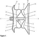
Figure 1 shows a cross-sectional view of the occlusion device in the relaxed condition according to one embodiment of the invention; -
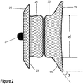
Figure 2 shows a side view of the embodiment ofFigure 1 , where the wire mesh structure becomes visible; -
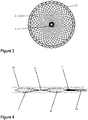
Figure 3 shows an end view of the embodiment ofFigures 1 and2 taken along the center axis A of the device when looking in the direction from the smaller first disk to the larger second disk; -
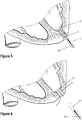
Figure 4 shows an embodiment by which the occlusion device is collapsed and located within the sheath of the delivery device; -
Figures 5 and 6 show two stages of a deployment procedure of the occluder in an apical hole of the human heart. -
Figures 1 and2 illustrate a first embodiment of the present invention, where the occlusion device is depicted in the relaxed condition, where the metal mesh components made of shape memory alloy wires are at their relaxed position. Afirst disk 2 having an enlargeddiameter flange portion 25, shown on the left, is adapted to be placed proximate an exterior end of the apical hole in the patient's heart wall. The exterior end is the end of the hole facing the outside of the heart wall. Thefirst disk 2 further comprises afirst shoulder portion 20 which is adapted to be placed within the apical hole near the exterior end. - Likewise, a
second disk 3 has an enlargeddiameter flange portion 35 which is adapted to be placed proximate an interior end of the apical hole, i.e. the end which is within the patient's heart. Asecond shoulder portion 30 is adapted to be placed within the hole near the interior end. With this construction, the enlarged diameter portions can engage opposing surfaces of the heart wall adjacent the apical hole. - The occluder further comprises a
central waist portion 4 which extends between the first andsecond disk portions central waist portion 4 is adapted to extend through the apical hole and connect the first andsecond shoulder portions - As can be taken from
Figure 1 , the first andsecond shoulder portions inner faces inner face corresponding shoulder portion central waist 4 and theinner faces - However, when the occluder is being deployed, the first and second disks are drawn apart from one another (see
Figures 4 and5 and the discussion below), such that thecentral waist portion 4 pulls the recessedinner faces Figure 1 to a mounted condition shown inFigures 5 and 6 where the previously recessed inner faces now become substantially flat surfaces. With this arrangement, expanding the two disks to move apart axially during deployment is resisted by the mesh structure of the recessedinner faces second shoulder portions inner faces - The
central waist portion 4 comprises first and secondside waist portions inner faces second shoulder portions Figure 1 . Thecentral waist portion 4 may be formed integrally as one piece with the entire occluder, which is fabricated in a heat shaping process of the shape memory mesh material. Thewaist portion 4 is highly contracted in comparison to the outer disk portions of the occluder and will typically have a diameter of about 2 mm. - The overall length of the
central waist portion 4 can be varied depending on the individual patient, but is at least 5 mm and generally in the range of 5 to 18 mm in length. Preferably the central waist portion is in the range of 5 to 12 mm. - The
side waist portions disk structure diameter flange portion shoulder portion respective part flange portions - The present design of the central waist portion in conjunction with the inner faces 22, 32 of the
shoulder portions disks - As shown in
Figures 1 and2 , an inner peripheral surface of the first enlargeddiameter flange portion 25 is expanded to define aperimeter edge 23 which, when mounted, will contact an exterior surface of the heart wall adjacent the apical hole. Likewise, an inner peripheral surface of the second enlargeddiameter flange portion 35 is expanded to define aperimeter edge 33 which, when mounted, will contact an interior surface of the heart wall adjacent the apical hole. - The
perimeter edge 33 of thesecond flange portion 35 is shaped differently, so as to match the shape of the heart wall from within. As shown inFigures 5 and 6 , the heart wall near the apical hole has an acute inclination angle with respect to the center axis A of the device. Preferably, the associatedperimeter edge 33 will have a matching inclination angle α with respect to the center axis A of about 65 degrees to 80 degrees. A typical inclination angle will be about 70 degrees. - As illustrated in the embodiment of
Figure 3 , the diameter of thefirst disk 2 for placement at the exterior surface is somewhat smaller that the diameter of thesecond disk 3 for placement on the interior heart wall. As an example thefirst disk 2 can have a diameter of 12 mm and the second disk 3 a diameter of 14 mm. These dimensions facilitate a better fit of the occluder when deployed, which is adapted to the anatomy of the inside and outside heart wall. - In another preferred embodiment, the present occlusion device comprises at least one blood-flow inhibiting filter attached to each of the two
disks Figure 1 , the fabric filters 6, 8 can be placed adjacent to the surface of theenlarged diameter portions filter fabrics respective shoulder portions disk flow restricting filters respective disks - In the present embodiment, the device comprises a
clamp 1 adapted for releasable attachment to a delivery device, as shown for example inFigures 1 and4 . Theclamp 1 can be provided with an internal or external threading for releasable attachment to the delivery device. Conventional devices provide clamps or connector portions on both ends of the double-disk occluder. The present design with only one clamp is patient friendly in terms of biocompatibility and can also aid endothelialization to a great extent. The collapsed configuration of the occluder as shown for example inFigure 4 is such that it can be delivered to an access site size of up to 34 Fr. - The placement of the present apical occlusion device is similar to that used in surgery for ventricle septal defect (VSD) and atrial septal defect (ASD) These are common and familiar procedures for the surgeon and requires much less time than the mentioned devices and procedures of the prior art. Another advantage is that the present occluder allows for adjustment to the length of the apical hole without harm to the myocardium tissue.
- The deployment of the present occluder is accomplished with a delivery device comprising a
sheath 11. Apusher device 10 can be screw-connected to theclamp 1 of the occluder (seeFigure 4 ) and thesheath 11 is brought into the target area. The pusher device pushes theinterior disk 3 out of the sheath as illustrated inFigure 5 . The sheath is then further retracted until resistance is felt from theinterior disk 3 when engaging the internal wall of the heart. Thesheath 11 is then further retracted to deploy the secondexternal disk 2 as shown inFigure 6 . Finally, the threadedclamp 1 is unscrewed from the pusher and the entire delivery device withsheath 11 can be withdrawn. - The following is a clinical example of utilization of the present device in a TAVR procedure.
- The left ventricular apical thickness of the patient's heart was computed from a tomographic scan to be 6.5 mm. During the procedure with a standard anterolateral minithoracotomy, two reinforced purse-string sutures were performed at the apex to prevent major bleeding in case of occluder failure.
- The TA-TAVR procedure was performed, and a 23 mm Sapien XT valve was implanted. Following the procedure, the Ascendra delivery system was extracted and we inserted a 9 mm apex occluder under fluoroscopic guidance. The model occlude employed had a shoulder diameter of 7mm.
- The distal part of the occluder was deployed in the LV and placed against the ventricular rim of the
sheath 11. Then, we performed a pullback of both thesheath 11 and the model occluder until we experienced a certain degree of resistance, meaning that the internal part of the occluder touched the apex opening. At that time, and without rapid cardiac pacing, we retrieved only thesheath 11 and thereby immediately deployed the external part of theoccluder 2 with a good result. - Only minor bleeding occurred that completely disappeared after protamine infusion. The occluder was still attached to the
pusher 10 of the delivery system and still fully available in case of need. After 20 minutes of perfect functioning of the model occluder, it was disconnected from the delivery system and the purse-string sutures were tied only for safety reasons. Patient recovery was uneventful and without complications related to the occluder, and we restored anticoagulation treatment. After a 3-month follow-up period, the patients was asymptomatic and in good condition. - As illustrated above, the application process of present occluder for closing an apical puncture is completely sutureless, and is performed in an easy and rapid manner. Less blood loss results and the healing time is shortened. Based on the success with the use of proven occluder delivery and application systems, the utilization of the present occluder system to the cardiac apex is safe and reliable. The special design of the adjustable waist and the single clamp construction make the occluder unique, efficient and safe to use.
Claims (12)
- An occlusion device, comprising:a central waist portion (4) extending between first and second disks (2, 3) disposed along a center axis (A), the device being formed of metal mesh comprising a plurality of metal strands made of shape memory alloy material,wherein the first disk (2) has a first enlarged diameter flange portion (25) adapted to be placed on an exterior surface of a patient's heart wall adjacent an exterior end of an apical hole in the heart wall,and an adjacent first shoulder portion (20) of smaller diameter adapted to be placed within the apical hole near the exterior end,wherein the second disk (3) has a second enlarged diameter portion (35) adapted to be placed on an interior surface of the heart wall adjacent the interior end of the apical hole,and an adjacent second shoulder portion (30) of smaller diameter adapted to be placed within the apical hole near the interior end, andwherein the central waist portion (4) is adapted to extend through the apical hole and connect the first and second disks (2, 3), while urging the disks (2, 3) toward one another when the device is in an expanded condition,characterized in thatthe first and second shoulder portions (20, 30) have respective inner faces (22, 32) lying opposite one another in the direction of the center axis (A), each inner face (22, 32) being concaved inwardly within its corresponding shoulder portion (20, 30) by an angle β between each of the inner faces (22, 32) and the central waist portion (4) so as to form a recess when the device is in a relaxed condition, andwhen in the expanded condition of the mounted device within the apical hole, the disks (2, 3) are urged toward one another by the tensioning arising from the mesh structure of the inner faces (22, 32) of the first and second shoulder portions (20, 30) which take on a flatter shape as they are pulled toward one another by the central waist portion (4).
- The occlusion device of claim 1, wherein the device can be placed into a collapsed configuration for delivery of the device into the apical hole of the patient through a lumen of a catheter.
- The occlusion device of claim 1 or 2, wherein the central waist portion (4) comprises first and second side waist portions (21, 31) connected respectively to the inner faces (22, 32) of the first and second shoulder portions (20, 30) at positions along the center axis (A).
- The occlusion device of claim 3, wherein the central waist portion (4) comprising the first and second side waist portions (21, 31) is formed integrally as one piece with the first and second disks.
- The occlusion device of any one of the preceding claims, wherein the central waist portion (4) has a length of in the range of 5 mm to 18 mm.
- The occlusion device of any one of the claims 1 to 5, wherein the inner faces (22, 23) of the shoulder portions (20, 30) and the central waist portion (4) are adapted to flex both axially and laterally such that the device is capable of adjusting to the length and orientation of the apical hole, while providing an inward biasing of the first and second disks (2, 3) toward one another.
- The occlusion device of any one of the preceding claims, wherein a peripheral surface of the first enlarged diameter flange portion (25) is expanded to define an inner perimeter edge (23) which, when mounted, contacts an exterior surface of the heart wall adjacent the apical hole.
- The occlusion device of any one of the preceding claims, wherein a peripheral surface of the second enlarged diameter flange portion (35) is expanded to define an inner perimeter edge (33) which, when mounted, contacts an interior surface of the heart wall adjacent the apical hole.
- The occlusion device of claim 8, wherein the perimeter edge (33) for contact with an interior surface of the heart wall has an inclination angle (α) with respect to the center axis (A) of about 65 degrees to 80 degrees.
- The occlusion device of any one of the preceding claims, wherein at least one blood flow inhibiting filter (6, 7; 8, 9) is provided in each of the first and second disks (2, 3).
- The occlusion device of claim 10, wherein two blood flow inhibiting filters (6, 7; 8. 9) are provided in each disk (2, 3), one disposed adjacent the enlarged diameter flange portion (25, 35) and the other disposed adjacent an inner face (22, 32) of the shoulder portion (20, 30).
- The occlusion device of any one of the preceding claims, wherein the first disk (2) includes a clamp (1) adapted for releasable attachment to a delivery device (10), in particular a threaded clamp (1).
Priority Applications (4)
| Application Number | Priority Date | Filing Date | Title |
|---|---|---|---|
| EP15186551.6A EP3146903B1 (en) | 2015-09-23 | 2015-09-23 | Occlusion device for closing an apical hole in the heart wall |
| US14/997,746 US20170079631A1 (en) | 2015-09-23 | 2016-01-18 | Occlusion device for closing an apical hole in the heart wall |
| RU2016136954A RU2016136954A (en) | 2015-09-23 | 2016-09-15 | OCCLUSION DEVICE FOR CLOSING AN APICAL HOLE IN THE HEART WALL |
| BR102016021637A BR102016021637A2 (en) | 2015-09-23 | 2016-09-21 | occlusion device to close an apical opening in the heart wall |
Applications Claiming Priority (1)
| Application Number | Priority Date | Filing Date | Title |
|---|---|---|---|
| EP15186551.6A EP3146903B1 (en) | 2015-09-23 | 2015-09-23 | Occlusion device for closing an apical hole in the heart wall |
Publications (2)
| Publication Number | Publication Date |
|---|---|
| EP3146903A1 EP3146903A1 (en) | 2017-03-29 |
| EP3146903B1 true EP3146903B1 (en) | 2019-05-08 |
Family
ID=54238243
Family Applications (1)
| Application Number | Title | Priority Date | Filing Date |
|---|---|---|---|
| EP15186551.6A Not-in-force EP3146903B1 (en) | 2015-09-23 | 2015-09-23 | Occlusion device for closing an apical hole in the heart wall |
Country Status (4)
| Country | Link |
|---|---|
| US (1) | US20170079631A1 (en) |
| EP (1) | EP3146903B1 (en) |
| BR (1) | BR102016021637A2 (en) |
| RU (1) | RU2016136954A (en) |
Families Citing this family (5)
| Publication number | Priority date | Publication date | Assignee | Title |
|---|---|---|---|---|
| CN209074752U (en) * | 2017-05-23 | 2019-07-09 | 杭州诺茂医疗科技有限公司 | A kind of occluder for left auricle being cross-linked |
| CN113648016A (en) * | 2018-03-02 | 2021-11-16 | 上海微创医疗器械(集团)有限公司 | Occluder and medical instrument |
| US11832805B2 (en) | 2019-08-26 | 2023-12-05 | St. Jude Medical, Cardiology Division, Inc. | Occluder with access passage and closure thereof |
| CN113081131B (en) * | 2021-04-06 | 2024-07-30 | 苏州茵络医疗器械有限公司 | Auxiliary system for transapical surgery |
| CN115153685B (en) * | 2022-08-09 | 2025-11-14 | 花沐医疗科技(上海)有限公司 | A biodegradable cardiac occluder for bilateral rivetless atrial septal defects |
Family Cites Families (7)
| Publication number | Priority date | Publication date | Assignee | Title |
|---|---|---|---|---|
| US9039724B2 (en) * | 2004-03-19 | 2015-05-26 | Aga Medical Corporation | Device for occluding vascular defects |
| CA2627285A1 (en) * | 2005-10-24 | 2007-10-25 | Nmt Medical, Inc. | Radiopaque bioabsorbable occluder |
| US8034061B2 (en) * | 2007-07-12 | 2011-10-11 | Aga Medical Corporation | Percutaneous catheter directed intravascular occlusion devices |
| US9414842B2 (en) * | 2007-10-12 | 2016-08-16 | St. Jude Medical, Cardiology Division, Inc. | Multi-component vascular device |
| US9526483B2 (en) | 2010-07-15 | 2016-12-27 | Medtronic Vascular Galway | Apical closure system |
| CN101933850B (en) * | 2010-09-16 | 2012-07-18 | 先健科技(深圳)有限公司 | Stopper and manufacturing method thereof |
| US9055937B2 (en) | 2011-04-01 | 2015-06-16 | Edwards Lifesciences Corporation | Apical puncture access and closure system |
-
2015
- 2015-09-23 EP EP15186551.6A patent/EP3146903B1/en not_active Not-in-force
-
2016
- 2016-01-18 US US14/997,746 patent/US20170079631A1/en not_active Abandoned
- 2016-09-15 RU RU2016136954A patent/RU2016136954A/en not_active Application Discontinuation
- 2016-09-21 BR BR102016021637A patent/BR102016021637A2/en not_active Application Discontinuation
Non-Patent Citations (1)
| Title |
|---|
| None * |
Also Published As
| Publication number | Publication date |
|---|---|
| EP3146903A1 (en) | 2017-03-29 |
| RU2016136954A (en) | 2018-03-21 |
| US20170079631A1 (en) | 2017-03-23 |
| BR102016021637A2 (en) | 2017-03-28 |
Similar Documents
| Publication | Publication Date | Title |
|---|---|---|
| US12440217B2 (en) | Percutaneous catheter directed intravascular occlusion devices | |
| US10463477B2 (en) | Retrievable devices for treating heart failure | |
| US11134934B2 (en) | Devices and methods for closing openings in tissue structures | |
| US8840655B2 (en) | Systems and devices for reducing the size of an internal tissue opening | |
| EP2004068B1 (en) | Deformable flap catch mechanism for occluder device | |
| US8715319B2 (en) | Catch member for septal occluder with adjustable-length center joint | |
| US20070265658A1 (en) | Anchoring and tethering system | |
| US20110093037A1 (en) | Compliant electrode for patent foramen ovale closure device | |
| WO2017015632A1 (en) | Device for securing heart valve leaflets | |
| US10758217B2 (en) | Implantable sealing device | |
| CN102985014A (en) | Medical implant and method of manufacturing same | |
| US20230329722A1 (en) | Left atrial appendage occlusion methods and devices | |
| JP2009532123A (en) | Variable length patent foramen ovale (PFO) occluder and catch system | |
| US20230255773A1 (en) | System and method for reshaping heart | |
| US20170079631A1 (en) | Occlusion device for closing an apical hole in the heart wall | |
| US20230218395A1 (en) | Compressible shunt implant | |
| EP4178464B1 (en) | Devices and methods for occlusion of vascular system abnormalities | |
| US12016569B2 (en) | Left atrial appendage occlusion methods and devices | |
| EP3368098B1 (en) | Inflow cannula and blood assist system | |
| US20240423635A1 (en) | Left atrial appendage occlusion methods and devices | |
| US11510678B2 (en) | Self-expanding ventricular partitioning device including anchor | |
| EP3884993A1 (en) | Device for valve regurgitation surgery and cardiac pacemaker lead fixation | |
| KR20180055856A (en) | Multifunctional occlusion device |
Legal Events
| Date | Code | Title | Description |
|---|---|---|---|
| PUAI | Public reference made under article 153(3) epc to a published international application that has entered the european phase |
Free format text: ORIGINAL CODE: 0009012 |
|
| STAA | Information on the status of an ep patent application or granted ep patent |
Free format text: STATUS: THE APPLICATION HAS BEEN PUBLISHED |
|
| AK | Designated contracting states |
Kind code of ref document: A1 Designated state(s): AL AT BE BG CH CY CZ DE DK EE ES FI FR GB GR HR HU IE IS IT LI LT LU LV MC MK MT NL NO PL PT RO RS SE SI SK SM TR |
|
| AX | Request for extension of the european patent |
Extension state: BA ME |
|
| STAA | Information on the status of an ep patent application or granted ep patent |
Free format text: STATUS: REQUEST FOR EXAMINATION WAS MADE |
|
| 17P | Request for examination filed |
Effective date: 20170929 |
|
| RBV | Designated contracting states (corrected) |
Designated state(s): AL AT BE BG CH CY CZ DE DK EE ES FI FR GB GR HR HU IE IS IT LI LT LU LV MC MK MT NL NO PL PT RO RS SE SI SK SM TR |
|
| GRAP | Despatch of communication of intention to grant a patent |
Free format text: ORIGINAL CODE: EPIDOSNIGR1 |
|
| STAA | Information on the status of an ep patent application or granted ep patent |
Free format text: STATUS: GRANT OF PATENT IS INTENDED |
|
| INTG | Intention to grant announced |
Effective date: 20181205 |
|
| GRAS | Grant fee paid |
Free format text: ORIGINAL CODE: EPIDOSNIGR3 |
|
| GRAA | (expected) grant |
Free format text: ORIGINAL CODE: 0009210 |
|
| STAA | Information on the status of an ep patent application or granted ep patent |
Free format text: STATUS: THE PATENT HAS BEEN GRANTED |
|
| RAP1 | Party data changed (applicant data changed or rights of an application transferred) |
Owner name: LEPU MEDICAL TECHNOLOGY (BEIJING) CO., LTD. |
|
| AK | Designated contracting states |
Kind code of ref document: B1 Designated state(s): AL AT BE BG CH CY CZ DE DK EE ES FI FR GB GR HR HU IE IS IT LI LT LU LV MC MK MT NL NO PL PT RO RS SE SI SK SM TR |
|
| REG | Reference to a national code |
Ref country code: GB Ref legal event code: FG4D |
|
| REG | Reference to a national code |
Ref country code: CH Ref legal event code: EP Ref country code: AT Ref legal event code: REF Ref document number: 1128937 Country of ref document: AT Kind code of ref document: T Effective date: 20190515 |
|
| REG | Reference to a national code |
Ref country code: DE Ref legal event code: R096 Ref document number: 602015029702 Country of ref document: DE Ref country code: IE Ref legal event code: FG4D |
|
| REG | Reference to a national code |
Ref country code: NL Ref legal event code: MP Effective date: 20190508 |
|
| REG | Reference to a national code |
Ref country code: LT Ref legal event code: MG4D |
|
| PG25 | Lapsed in a contracting state [announced via postgrant information from national office to epo] |
Ref country code: FI Free format text: LAPSE BECAUSE OF FAILURE TO SUBMIT A TRANSLATION OF THE DESCRIPTION OR TO PAY THE FEE WITHIN THE PRESCRIBED TIME-LIMIT Effective date: 20190508 Ref country code: AL Free format text: LAPSE BECAUSE OF FAILURE TO SUBMIT A TRANSLATION OF THE DESCRIPTION OR TO PAY THE FEE WITHIN THE PRESCRIBED TIME-LIMIT Effective date: 20190508 Ref country code: NO Free format text: LAPSE BECAUSE OF FAILURE TO SUBMIT A TRANSLATION OF THE DESCRIPTION OR TO PAY THE FEE WITHIN THE PRESCRIBED TIME-LIMIT Effective date: 20190808 Ref country code: PT Free format text: LAPSE BECAUSE OF FAILURE TO SUBMIT A TRANSLATION OF THE DESCRIPTION OR TO PAY THE FEE WITHIN THE PRESCRIBED TIME-LIMIT Effective date: 20190908 Ref country code: HR Free format text: LAPSE BECAUSE OF FAILURE TO SUBMIT A TRANSLATION OF THE DESCRIPTION OR TO PAY THE FEE WITHIN THE PRESCRIBED TIME-LIMIT Effective date: 20190508 Ref country code: SE Free format text: LAPSE BECAUSE OF FAILURE TO SUBMIT A TRANSLATION OF THE DESCRIPTION OR TO PAY THE FEE WITHIN THE PRESCRIBED TIME-LIMIT Effective date: 20190508 Ref country code: ES Free format text: LAPSE BECAUSE OF FAILURE TO SUBMIT A TRANSLATION OF THE DESCRIPTION OR TO PAY THE FEE WITHIN THE PRESCRIBED TIME-LIMIT Effective date: 20190508 Ref country code: LT Free format text: LAPSE BECAUSE OF FAILURE TO SUBMIT A TRANSLATION OF THE DESCRIPTION OR TO PAY THE FEE WITHIN THE PRESCRIBED TIME-LIMIT Effective date: 20190508 Ref country code: NL Free format text: LAPSE BECAUSE OF FAILURE TO SUBMIT A TRANSLATION OF THE DESCRIPTION OR TO PAY THE FEE WITHIN THE PRESCRIBED TIME-LIMIT Effective date: 20190508 |
|
| PG25 | Lapsed in a contracting state [announced via postgrant information from national office to epo] |
Ref country code: RS Free format text: LAPSE BECAUSE OF FAILURE TO SUBMIT A TRANSLATION OF THE DESCRIPTION OR TO PAY THE FEE WITHIN THE PRESCRIBED TIME-LIMIT Effective date: 20190508 Ref country code: LV Free format text: LAPSE BECAUSE OF FAILURE TO SUBMIT A TRANSLATION OF THE DESCRIPTION OR TO PAY THE FEE WITHIN THE PRESCRIBED TIME-LIMIT Effective date: 20190508 Ref country code: GR Free format text: LAPSE BECAUSE OF FAILURE TO SUBMIT A TRANSLATION OF THE DESCRIPTION OR TO PAY THE FEE WITHIN THE PRESCRIBED TIME-LIMIT Effective date: 20190809 Ref country code: BG Free format text: LAPSE BECAUSE OF FAILURE TO SUBMIT A TRANSLATION OF THE DESCRIPTION OR TO PAY THE FEE WITHIN THE PRESCRIBED TIME-LIMIT Effective date: 20190808 |
|
| REG | Reference to a national code |
Ref country code: AT Ref legal event code: MK05 Ref document number: 1128937 Country of ref document: AT Kind code of ref document: T Effective date: 20190508 |
|
| PG25 | Lapsed in a contracting state [announced via postgrant information from national office to epo] |
Ref country code: CZ Free format text: LAPSE BECAUSE OF FAILURE TO SUBMIT A TRANSLATION OF THE DESCRIPTION OR TO PAY THE FEE WITHIN THE PRESCRIBED TIME-LIMIT Effective date: 20190508 Ref country code: SK Free format text: LAPSE BECAUSE OF FAILURE TO SUBMIT A TRANSLATION OF THE DESCRIPTION OR TO PAY THE FEE WITHIN THE PRESCRIBED TIME-LIMIT Effective date: 20190508 Ref country code: AT Free format text: LAPSE BECAUSE OF FAILURE TO SUBMIT A TRANSLATION OF THE DESCRIPTION OR TO PAY THE FEE WITHIN THE PRESCRIBED TIME-LIMIT Effective date: 20190508 Ref country code: EE Free format text: LAPSE BECAUSE OF FAILURE TO SUBMIT A TRANSLATION OF THE DESCRIPTION OR TO PAY THE FEE WITHIN THE PRESCRIBED TIME-LIMIT Effective date: 20190508 Ref country code: DK Free format text: LAPSE BECAUSE OF FAILURE TO SUBMIT A TRANSLATION OF THE DESCRIPTION OR TO PAY THE FEE WITHIN THE PRESCRIBED TIME-LIMIT Effective date: 20190508 Ref country code: RO Free format text: LAPSE BECAUSE OF FAILURE TO SUBMIT A TRANSLATION OF THE DESCRIPTION OR TO PAY THE FEE WITHIN THE PRESCRIBED TIME-LIMIT Effective date: 20190508 |
|
| REG | Reference to a national code |
Ref country code: DE Ref legal event code: R097 Ref document number: 602015029702 Country of ref document: DE |
|
| PG25 | Lapsed in a contracting state [announced via postgrant information from national office to epo] |
Ref country code: IT Free format text: LAPSE BECAUSE OF FAILURE TO SUBMIT A TRANSLATION OF THE DESCRIPTION OR TO PAY THE FEE WITHIN THE PRESCRIBED TIME-LIMIT Effective date: 20190508 Ref country code: SM Free format text: LAPSE BECAUSE OF FAILURE TO SUBMIT A TRANSLATION OF THE DESCRIPTION OR TO PAY THE FEE WITHIN THE PRESCRIBED TIME-LIMIT Effective date: 20190508 |
|
| PLBE | No opposition filed within time limit |
Free format text: ORIGINAL CODE: 0009261 |
|
| STAA | Information on the status of an ep patent application or granted ep patent |
Free format text: STATUS: NO OPPOSITION FILED WITHIN TIME LIMIT |
|
| PG25 | Lapsed in a contracting state [announced via postgrant information from national office to epo] |
Ref country code: TR Free format text: LAPSE BECAUSE OF FAILURE TO SUBMIT A TRANSLATION OF THE DESCRIPTION OR TO PAY THE FEE WITHIN THE PRESCRIBED TIME-LIMIT Effective date: 20190508 |
|
| REG | Reference to a national code |
Ref country code: DE Ref legal event code: R119 Ref document number: 602015029702 Country of ref document: DE |
|
| 26N | No opposition filed |
Effective date: 20200211 |
|
| PG25 | Lapsed in a contracting state [announced via postgrant information from national office to epo] |
Ref country code: PL Free format text: LAPSE BECAUSE OF FAILURE TO SUBMIT A TRANSLATION OF THE DESCRIPTION OR TO PAY THE FEE WITHIN THE PRESCRIBED TIME-LIMIT Effective date: 20190508 |
|
| PG25 | Lapsed in a contracting state [announced via postgrant information from national office to epo] |
Ref country code: SI Free format text: LAPSE BECAUSE OF FAILURE TO SUBMIT A TRANSLATION OF THE DESCRIPTION OR TO PAY THE FEE WITHIN THE PRESCRIBED TIME-LIMIT Effective date: 20190508 Ref country code: MC Free format text: LAPSE BECAUSE OF FAILURE TO SUBMIT A TRANSLATION OF THE DESCRIPTION OR TO PAY THE FEE WITHIN THE PRESCRIBED TIME-LIMIT Effective date: 20190508 |
|
| REG | Reference to a national code |
Ref country code: CH Ref legal event code: PL |
|
| PG25 | Lapsed in a contracting state [announced via postgrant information from national office to epo] |
Ref country code: LI Free format text: LAPSE BECAUSE OF NON-PAYMENT OF DUE FEES Effective date: 20190930 Ref country code: LU Free format text: LAPSE BECAUSE OF NON-PAYMENT OF DUE FEES Effective date: 20190923 Ref country code: IE Free format text: LAPSE BECAUSE OF NON-PAYMENT OF DUE FEES Effective date: 20190923 Ref country code: DE Free format text: LAPSE BECAUSE OF NON-PAYMENT OF DUE FEES Effective date: 20200401 Ref country code: CH Free format text: LAPSE BECAUSE OF NON-PAYMENT OF DUE FEES Effective date: 20190930 |
|
| REG | Reference to a national code |
Ref country code: BE Ref legal event code: MM Effective date: 20190930 |
|
| PG25 | Lapsed in a contracting state [announced via postgrant information from national office to epo] |
Ref country code: BE Free format text: LAPSE BECAUSE OF NON-PAYMENT OF DUE FEES Effective date: 20190930 |
|
| GBPC | Gb: european patent ceased through non-payment of renewal fee |
Effective date: 20190923 |
|
| PG25 | Lapsed in a contracting state [announced via postgrant information from national office to epo] |
Ref country code: GB Free format text: LAPSE BECAUSE OF NON-PAYMENT OF DUE FEES Effective date: 20190923 Ref country code: FR Free format text: LAPSE BECAUSE OF NON-PAYMENT OF DUE FEES Effective date: 20190930 |
|
| PG25 | Lapsed in a contracting state [announced via postgrant information from national office to epo] |
Ref country code: CY Free format text: LAPSE BECAUSE OF FAILURE TO SUBMIT A TRANSLATION OF THE DESCRIPTION OR TO PAY THE FEE WITHIN THE PRESCRIBED TIME-LIMIT Effective date: 20190508 |
|
| PG25 | Lapsed in a contracting state [announced via postgrant information from national office to epo] |
Ref country code: IS Free format text: LAPSE BECAUSE OF FAILURE TO SUBMIT A TRANSLATION OF THE DESCRIPTION OR TO PAY THE FEE WITHIN THE PRESCRIBED TIME-LIMIT Effective date: 20190908 |
|
| PG25 | Lapsed in a contracting state [announced via postgrant information from national office to epo] |
Ref country code: MT Free format text: LAPSE BECAUSE OF FAILURE TO SUBMIT A TRANSLATION OF THE DESCRIPTION OR TO PAY THE FEE WITHIN THE PRESCRIBED TIME-LIMIT Effective date: 20190508 Ref country code: HU Free format text: LAPSE BECAUSE OF FAILURE TO SUBMIT A TRANSLATION OF THE DESCRIPTION OR TO PAY THE FEE WITHIN THE PRESCRIBED TIME-LIMIT; INVALID AB INITIO Effective date: 20150923 |
|
| PG25 | Lapsed in a contracting state [announced via postgrant information from national office to epo] |
Ref country code: MK Free format text: LAPSE BECAUSE OF FAILURE TO SUBMIT A TRANSLATION OF THE DESCRIPTION OR TO PAY THE FEE WITHIN THE PRESCRIBED TIME-LIMIT Effective date: 20190508 |