EP3146900A1 - Medical image photographing apparatus and medical image correction method using depth camera - Google Patents
Medical image photographing apparatus and medical image correction method using depth camera Download PDFInfo
- Publication number
- EP3146900A1 EP3146900A1 EP15796933.8A EP15796933A EP3146900A1 EP 3146900 A1 EP3146900 A1 EP 3146900A1 EP 15796933 A EP15796933 A EP 15796933A EP 3146900 A1 EP3146900 A1 EP 3146900A1
- Authority
- EP
- European Patent Office
- Prior art keywords
- subject
- data
- radiographing
- depth
- radiograph
- Prior art date
- Legal status (The legal status is an assumption and is not a legal conclusion. Google has not performed a legal analysis and makes no representation as to the accuracy of the status listed.)
- Granted
Links
Images


Classifications
-
- A—HUMAN NECESSITIES
- A61—MEDICAL OR VETERINARY SCIENCE; HYGIENE
- A61B—DIAGNOSIS; SURGERY; IDENTIFICATION
- A61B6/00—Apparatus or devices for radiation diagnosis; Apparatus or devices for radiation diagnosis combined with radiation therapy equipment
- A61B6/52—Devices using data or image processing specially adapted for radiation diagnosis
- A61B6/5205—Devices using data or image processing specially adapted for radiation diagnosis involving processing of raw data to produce diagnostic data
-
- A—HUMAN NECESSITIES
- A61—MEDICAL OR VETERINARY SCIENCE; HYGIENE
- A61B—DIAGNOSIS; SURGERY; IDENTIFICATION
- A61B6/00—Apparatus or devices for radiation diagnosis; Apparatus or devices for radiation diagnosis combined with radiation therapy equipment
- A61B6/02—Arrangements for diagnosis sequentially in different planes; Stereoscopic radiation diagnosis
- A61B6/03—Computed tomography [CT]
-
- G—PHYSICS
- G06—COMPUTING OR CALCULATING; COUNTING
- G06T—IMAGE DATA PROCESSING OR GENERATION, IN GENERAL
- G06T5/00—Image enhancement or restoration
- G06T5/50—Image enhancement or restoration using two or more images, e.g. averaging or subtraction
-
- A—HUMAN NECESSITIES
- A61—MEDICAL OR VETERINARY SCIENCE; HYGIENE
- A61B—DIAGNOSIS; SURGERY; IDENTIFICATION
- A61B6/00—Apparatus or devices for radiation diagnosis; Apparatus or devices for radiation diagnosis combined with radiation therapy equipment
-
- A—HUMAN NECESSITIES
- A61—MEDICAL OR VETERINARY SCIENCE; HYGIENE
- A61B—DIAGNOSIS; SURGERY; IDENTIFICATION
- A61B6/00—Apparatus or devices for radiation diagnosis; Apparatus or devices for radiation diagnosis combined with radiation therapy equipment
- A61B6/02—Arrangements for diagnosis sequentially in different planes; Stereoscopic radiation diagnosis
- A61B6/03—Computed tomography [CT]
- A61B6/032—Transmission computed tomography [CT]
-
- A—HUMAN NECESSITIES
- A61—MEDICAL OR VETERINARY SCIENCE; HYGIENE
- A61B—DIAGNOSIS; SURGERY; IDENTIFICATION
- A61B6/00—Apparatus or devices for radiation diagnosis; Apparatus or devices for radiation diagnosis combined with radiation therapy equipment
- A61B6/52—Devices using data or image processing specially adapted for radiation diagnosis
- A61B6/5258—Devices using data or image processing specially adapted for radiation diagnosis involving detection or reduction of artifacts or noise
- A61B6/5264—Devices using data or image processing specially adapted for radiation diagnosis involving detection or reduction of artifacts or noise due to motion
-
- A—HUMAN NECESSITIES
- A61—MEDICAL OR VETERINARY SCIENCE; HYGIENE
- A61B—DIAGNOSIS; SURGERY; IDENTIFICATION
- A61B6/00—Apparatus or devices for radiation diagnosis; Apparatus or devices for radiation diagnosis combined with radiation therapy equipment
- A61B6/54—Control of apparatus or devices for radiation diagnosis
-
- H—ELECTRICITY
- H04—ELECTRIC COMMUNICATION TECHNIQUE
- H04N—PICTORIAL COMMUNICATION, e.g. TELEVISION
- H04N19/00—Methods or arrangements for coding, decoding, compressing or decompressing digital video signals
- H04N19/50—Methods or arrangements for coding, decoding, compressing or decompressing digital video signals using predictive coding
- H04N19/503—Methods or arrangements for coding, decoding, compressing or decompressing digital video signals using predictive coding involving temporal prediction
- H04N19/51—Motion estimation or motion compensation
-
- A—HUMAN NECESSITIES
- A61—MEDICAL OR VETERINARY SCIENCE; HYGIENE
- A61B—DIAGNOSIS; SURGERY; IDENTIFICATION
- A61B5/00—Measuring for diagnostic purposes; Identification of persons
- A61B5/0059—Measuring for diagnostic purposes; Identification of persons using light, e.g. diagnosis by transillumination, diascopy, fluorescence
- A61B5/0077—Devices for viewing the surface of the body, e.g. camera, magnifying lens
-
- A—HUMAN NECESSITIES
- A61—MEDICAL OR VETERINARY SCIENCE; HYGIENE
- A61B—DIAGNOSIS; SURGERY; IDENTIFICATION
- A61B5/00—Measuring for diagnostic purposes; Identification of persons
- A61B5/72—Signal processing specially adapted for physiological signals or for diagnostic purposes
- A61B5/7203—Signal processing specially adapted for physiological signals or for diagnostic purposes for noise prevention, reduction or removal
- A61B5/7207—Signal processing specially adapted for physiological signals or for diagnostic purposes for noise prevention, reduction or removal of noise induced by motion artifacts
-
- G—PHYSICS
- G01—MEASURING; TESTING
- G01R—MEASURING ELECTRIC VARIABLES; MEASURING MAGNETIC VARIABLES
- G01R33/00—Arrangements or instruments for measuring magnetic variables
- G01R33/20—Arrangements or instruments for measuring magnetic variables involving magnetic resonance
- G01R33/28—Details of apparatus provided for in groups G01R33/44 - G01R33/64
- G01R33/283—Intercom or optical viewing arrangements, structurally associated with NMR apparatus
-
- G—PHYSICS
- G01—MEASURING; TESTING
- G01R—MEASURING ELECTRIC VARIABLES; MEASURING MAGNETIC VARIABLES
- G01R33/00—Arrangements or instruments for measuring magnetic variables
- G01R33/20—Arrangements or instruments for measuring magnetic variables involving magnetic resonance
- G01R33/44—Arrangements or instruments for measuring magnetic variables involving magnetic resonance using nuclear magnetic resonance [NMR]
- G01R33/48—NMR imaging systems
- G01R33/54—Signal processing systems, e.g. using pulse sequences ; Generation or control of pulse sequences; Operator console
- G01R33/56—Image enhancement or correction, e.g. subtraction or averaging techniques, e.g. improvement of signal-to-noise ratio and resolution
- G01R33/565—Correction of image distortions, e.g. due to magnetic field inhomogeneities
- G01R33/56509—Correction of image distortions, e.g. due to magnetic field inhomogeneities due to motion, displacement or flow, e.g. gradient moment nulling
-
- G—PHYSICS
- G06—COMPUTING OR CALCULATING; COUNTING
- G06T—IMAGE DATA PROCESSING OR GENERATION, IN GENERAL
- G06T2207/00—Indexing scheme for image analysis or image enhancement
- G06T2207/10—Image acquisition modality
- G06T2207/10028—Range image; Depth image; 3D point clouds
-
- G—PHYSICS
- G06—COMPUTING OR CALCULATING; COUNTING
- G06T—IMAGE DATA PROCESSING OR GENERATION, IN GENERAL
- G06T2207/00—Indexing scheme for image analysis or image enhancement
- G06T2207/10—Image acquisition modality
- G06T2207/10116—X-ray image
-
- G—PHYSICS
- G06—COMPUTING OR CALCULATING; COUNTING
- G06T—IMAGE DATA PROCESSING OR GENERATION, IN GENERAL
- G06T2207/00—Indexing scheme for image analysis or image enhancement
- G06T2207/20—Special algorithmic details
- G06T2207/20212—Image combination
- G06T2207/20221—Image fusion; Image merging
Definitions
- the present invention relates, generally to radiographing apparatus and method of correcting a medical radiograph.
- a conventional method of correcting a medical radiograph is as follows.
- a medical radiograph is corrected by outputting real-time movement information of a subject captured by a movement detection module; converting and outputting the real-time moving information to three-axis parameters by a movement calculation module; operating an operating motor by an operation module in response to the three-axis parameters; and moving by a distance that the subject has actually moved in response to the operation of the operating motor by a medical image data obtaining module.
- a post image processing method that reconstructs a radiographed image at first, and then performs an image processing is used.
- the above document is problematic when an equipment vibration, or a positional change of a subject is small thus the radiographing device is not repositioned.
- a radiograph is degraded when a positional change of a subject is small, whereby the X-ray radiographing device is not repositioned and thus the image correction is not performed.
- a radiographing time delay is caused since a movement of the X-ray radiographing device and a data acquisition of the medical radiograph are not performed in real time. Further, when the movement of the X-ray radiographing device or obtained movement information is incorrect, a completely different radiograph may be obtained.
- original data may be damaged since an image correction is performed after performing a reconstruction algorithm.
- X-ray radiographs such as CTs are used for diagnoses purposes.
- X-ray radiographs are images of internal human organs and are unfamiliar to ordinary persons who are not medical workers.
- dental clinics and in the plastic surgery field there is a request for checking a dimensional change in a surface of the body such as face after a procedure; however, the X-ray radiograph alone is not enough to meet such a requirement.
- One of the objects of the present invention is solve the problems of the prior art as described above.
- an embodiment of the present invention provides a computer readable medium that encodes a computer program which implements a system for radiographing a medical radiograph by using a depth camera, and a method of correcting the medical radiograph by using a depth camera, whereby the computer readable medium and the method are capable of obtaining depth data of a subject by using a depth camera, calculating a movement vector of the subject by using an optical flow algorithm, correcting a radiograph by using an affine transform, and performing a reconstruction algorithm when a position of the subject has changed by a vibration of a CT radiographing device or by a movement of a patient.
- the radiograph is corrected in real time without damage to original data and without movement the CT radiographing device.
- a radiographing device for a medical radiograph in which a clear 3D surface radiograph is obtained by using a depth camera.
- a radiographing apparatus for a medical radiograph, the radiographing apparatus including: an X-ray radiographing device radiographing a subject, and obtaining medical radiograph data of the subject; a depth camera radiographing the subject, and obtaining depth data of the subject; a controller controlling the X-ray radiographing device and the depth camera to obtain the medical radiograph data and the depth data of the subject at the same time; a correction unit correcting the medical radiograph data transmitted from the X-ray radiographing device by using the depth data transmitted from the depth camera; and a reconstruction unit performing a reconstruction algorithm based on the corrected medical radiograph data.
- a method of correcting a medical radiograph including: radiographing a subject and obtaining medical radiograph data of the subject by an X-ray radiographing device, and, at the same time, radiographing the subject and obtaining depth data of the subject by a depth camera; calculating movement information of the subject by comparing two neighboring frames of the depth data, and correcting the medical radiograph data by reflecting the calculated moving information to corresponding medical radiograph data by a correction unit; and performing a reconstruction algorithm based on the corrected medical radiograph data.
- the calculating of the movement information and the correcting of the medical radiograph data may include: setting an N-1th (N is an integer) frame of the depth data as a reference frame; obtaining movement information of the subject by comparing the reference frame (N-1th frame) of the depth data to a current frame (Nth frame) thereof; determining whether the movement information of the subject exceeds a predetermined threshold; and a correcting corresponding medical radiograph data by applying the movement information to an affine conversion formula when the movement information exceeds the predetermined threshold.
- a computer readable medium that encodes a computer program that implements the method of correcting the medical radiograph
- a damaged radiograph caused by a vibration of an equipment of by a movement of a patient while radiographing is corrected is performed based on original data, and not based on a reconstructed radiograph.
- a precise correction may be obtained.
- a radiographing time delay does not occur since the acquisition of medical radiograph data and the correction of the medical radiograph are performed in real time.
- the radiographing device is not moved to correct the radiograph, and thus the radiograph is corrected even a small movement of the subject compared to the conventional technique.
- a depth surface image of the subject is obtained by using the depth camera.
- the depth surface image is composed with a medical radiograph (for example, an X-ray CT radiograph) obtained from the X-ray radiographing device such that a clear 3D surface radiograph of the subject 10 is obtained.
- a medical radiograph for example, an X-ray CT radiograph
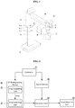
- FIG. 1 is a view for explaining a computed tomography (CT) radiographing device according to an embodiment of the present invention for explaining a concept of a method of correcting a medical radiograph by using a depth camera
- FIG. 2 is a block diagram showing a configuration of a CT radiographing device with a medical radiograph correction device for implementing the method of correcting the medical radiograph by using the depth camera according to the embodiment of the present invention.
- CT computed tomography
- FIGS. 1 and 2 an apparatus for correcting a medical radiograph will be described.
- the CT radiographing device 50 for the medical radiograph includes: a base 51 installed on a ground surface; a column 52 standing up from the base 51; an elevating unit 53 capable of moving in vertical directions along the column 52; a rotation arm supporting unit 54 extending from the elevating unit 53 in a horizontal direction; and a rotation arm 55 rotatably provided in a lower part of the rotation arm supporting unit 54.
- the radiographing apparatus for the medical radiograph includes an X-ray radiographing device radiographing a subject 10 and obtaining a medical radiograph data of the subject 10, and a first depth camera 40 provided in the radiographing apparatus and measuring a movement of the subject 10.
- the CT radiographing device 50 is used as an example of the X-ray radiographing device, and CT data is used as an example of medical radiograph data.
- the CT radiographing device 50 further includes an X-ray irradiating unit 20 irradiating X-rays and an X-ray detecting unit 30 detecting the X-rays passing through the subject 10.
- the X-ray irradiating unit 20 and the X-ray detecting unit 30 are respectively provided in both ends of the rotation arm 55 to face each other.
- the first depth camera 40 refers to a camera that generates a depth data for each pixel of the radiographed subject 10 based on a time of flight (TOF) of the X-rays, the time of flight (TOF) is an elapsed time in which light irradiated from the depth camera 40 is returned by being reflected by the subject 10.
- the first depth camera 40 may include a light source (for example, LED) to irradiate light toward the subject 10.
- the first depth camera 40 according to the embodiment of the present invention is provided in the rotation arm 50. However, it is not limited thereto and the first depth camera 40 may be provided in the column 52, or in the elevating unit 53. In other words, positions and number of the first depth camera 40 are not limited.
- the medical radiograph correcting device is capable of controlling the CT radiographing device 50 and the first depth camera 40 such that the CT data and the depth data are obtained at the same time, and includes a controller 70 that controls the CT radiographing device 50 and the first depth camera 40 to transmit the obtained radiograph data and the depth data.
- the medical radiograph correction device includes a correction unit 60 correcting a radiograph by using the radiograph data and the depth data that are transmitted from the CT radiographing device 50 and the first depth camera 40.
- FIG. 3 is a flowchart explaining a method of correcting a medical radiograph by using a depth camera according to an embodiment of the present invention
- FIG. 4 is a flowchart explaining a process of correcting a medical radiograph performed in a correction unit according to an embodiment of the present invention.
- the CT radiographing device 50 and the first depth camera 40 image the subject 10 (S10).
- the controller 70 controls the X-ray irradiating unit 20 to irradiate X-rays toward the subject 10, controls the X-ray detecting unit 30 to detect the X-rays that have passed through the subject 10, and obtains CT data of the subject 10.
- the controller 70 controls the first depth camera 40 to image the subject 10 and obtains the depth data thereof.
- the CT radiographing device 50 and the first depth camera 40 transmit the obtained data to the correction unit 60.
- the correction unit 60 corrects a CT radiograph by using the CT data and the depth data (S20).
- an N-1th frame of the depth data is set as a reference frame (S201).
- the movement information of the subject 10 is measured by comparing the reference frame (N-1th frame) to a current frame (S202). In other words, differences in pixel values between the reference frame and the current frame are calculated. A movement vector is calculated based on the calculated differences and is determined as movement information of the subject 10.
- the movement information may be measured in a pixel unit as described above. However, persons skilled in the art may know that the movement information may be measured in a macro-block unit.
- an optical flow algorithm may be used for calculating values of the motion vector.
- each pixel changes in its brightness and such a change in contrast is called an optical flow.
- a movement vector of two succeeding images of the subject 10 may be calculated by using optical flow information. In other words, movement information of the subject 10 is calculated.
- a calculation process is well known in the art, thus a detailed description of the calculating process is omitted in the present invention.
- the movement information is compared to a predetermined threshold (S203).
- the threshold may be changed by an experiment such that the threshold determines whether a radiograph correction is performed when the subject 10 has moved by some degree.
- a common threshold may be applied to all depth data, or a different threshold may be applied to each frame.
- the corresponding radiograph data is corrected by applying an affine transform to the corresponding CT data based on the movement information calculated in S203 to (S204).
- a sequence in which a movement of the subject 10 occurs is known by previous information, for example, when time duration from the beginning of the radiograph to the end thereof, in other words, a total radiographing time, is assumed to be 600 seconds and 500 radiographs are radiographed during the total radiographing time.
- the movement is known by the depth data.
- the CT radiograph is corrected by applying an affine transform to a 250 th radiograph that is radiographed at 300 seconds, in other words, CT data that temporally corresponds to a current frame (Nth frame) of the depth data.
- the affine transform used when correcting the CT radiograph (S204) is a conventional method such as rotating, moving in parallel, scaling, shearing, etc. of an image. For example, when the movement information of the subject 10 measured in S202 includes a rotation about 45 degrees, a shift in x-axis by 5, and a shift in y-axis by 10, then, the above values may be substituted to an affine transform equation to correct the CT radiograph.
- the affine transform is well known in the art and is used in various fields. Thus, a detailed description of transformation is omitted in the embodiment of the present invention.
- the CT radiographing device 50 and the first depth camera 40 repeatedly image the subject 10 (S10), and the CT data is repeatedly corrected (S20) until the last frame of the depth data in which the CT radiographing is finished is obtained (S30).
- the CT data corrected by the method of correcting the medical radiograph according to the embodiment of the present invention may be reconstructed to a CT radiograph by using a conventional reconstruction algorithm by a reconstruction unit 80.
- Image quality of the reconstructed CT radiograph is better than that of a radiograph obtained by using a conventional method.
- the CT radiographing device 50 is used as an X-ray radiographing device.
- a magnetic resonance imaging may be used as the X-ray radiographing device, thus the present is not limited thereto.
- the optical flow algorithm and the affine transform are used as imaging processing techniques for correcting a medical radiograph; however, it is not limited thereto.
- the method of correcting a medical radiograph by using the depth camera according to the present invention as described above may be realized in the form of program instructions which may be implemented through various computer components, and may be recorded in a computer-readable storage medium.
- the computer-readable storage medium may include a program instruction, a data file, a data structure, and the like either alone or in combination thereof.
- the program instruction recorded in the computer-readable storage medium may be any program instruction particularly designed and structured for the present invention or known to those skilled in the field of computer software.
- Examples of the computer-readable storage medium include magnetic recording media such as hard disks, to floppy disks and magnetic tapes, optical data storage media such as CD-ROMs or DVD-ROMs, magneto-optical media such as floptical disks, and hardware devices, such as read-only memory (ROM), random-access memory (RAM), and flash memory, which are particularly structured to store and implement the program instruction.
- Examples of the program instruction include not only a mechanical language code formatted by a compiler but also a high level language code which may be implemented by a computer using an interpreter.
- the hardware devices may be configured to be operated by one or more software modules or vice versa to conduct the processes according to the present invention.
- FIG. 5 is a block diagram showing a configuration of radiographing apparatus for a medical radiograph for implementing a method of a medical radiograph by using a depth camera according to an embodiment of the present invention.
- a method of obtaining a 3D surface radiograph by using the depth camera is as follows.
- a second depth camera 40-1 and a third depth camera 40-2 are provided in front of the elevating unit 53 to face each other.
- the second depth camera 40-1 radiographs a first area of the subject 10 and obtains a depth surface image of the first area.
- the third depth camera 40-2 radiographs a second area of the subject 10 and obtains a depth surface image of the second area.
- the second depth camera 40-1 and the third depth camera 40-2 may scan and radiograph the subject 10 by movement in upward and downward directions by the controller 70 since the second depth camera 40-1 and the third depth camera 40-2 are disposed in front of the elevating unit 53.
- a fourth depth camera 40-3 is provided in front of the column 52, radiographs the other area of the subject 10, and obtains a depth surface image of the other area.
- the radiographing apparatus includes three depth cameras 40-1, 40-2, and 40-3. However, it is not limited thereto.
- the depth camera may be provided in one, two, or more than four.
- the depth cameras 40-1, 40-2, and 40-3 transmit the surface depth radiographs obtained from the subject 10 to a composition unit 90.
- the CT radiographing device 50 radiographs the subject 10, obtains a medical radiograph (for example, X-ray CT radiograph) of the subject 10, and transmits the medical radiograph to the composition unit 90.
- a medical radiograph for example, X-ray CT radiograph
- the composition unit 90 performs a composition by matching the transmitted depth surface images and the medical radiograph of the subject 10.
- a 3D depth surface image of the subject 10 is obtained by matching the radiographs.
- the method of composing a radiograph is well known in the art, thus detailed description thereof is omitted.
- depth surface images obtained from the depth cameras 40-1, 40-2, and 40-3 are used for composing the radiograph, thus a clear 3D surface radiograph of the subject 10 may be generated.
Landscapes
- Health & Medical Sciences (AREA)
- Life Sciences & Earth Sciences (AREA)
- Engineering & Computer Science (AREA)
- Medical Informatics (AREA)
- Physics & Mathematics (AREA)
- Biomedical Technology (AREA)
- Animal Behavior & Ethology (AREA)
- Biophysics (AREA)
- Nuclear Medicine, Radiotherapy & Molecular Imaging (AREA)
- Optics & Photonics (AREA)
- Pathology (AREA)
- Radiology & Medical Imaging (AREA)
- Veterinary Medicine (AREA)
- Heart & Thoracic Surgery (AREA)
- Molecular Biology (AREA)
- Surgery (AREA)
- High Energy & Nuclear Physics (AREA)
- General Health & Medical Sciences (AREA)
- Public Health (AREA)
- Computer Vision & Pattern Recognition (AREA)
- Theoretical Computer Science (AREA)
- Pulmonology (AREA)
- Multimedia (AREA)
- Signal Processing (AREA)
- General Physics & Mathematics (AREA)
- Apparatus For Radiation Diagnosis (AREA)
Abstract
Description
- The present invention relates, generally to radiographing apparatus and method of correcting a medical radiograph.
- A conventional method of correcting a medical radiograph is as follows.
- A reference document of International Publication No.
WO 2013/162201 A1 (published on 31 October 2013 entitled "METHOD FOR TRACKING MOTION OF SUBJECT IN REAL TIME AND FOR CORRECTING MEDICAL IMAGE") discloses a conventional method of correcting a medical radiograph. - In the above document, a medical radiograph is corrected by outputting real-time movement information of a subject captured by a movement detection module; converting and outputting the real-time moving information to three-axis parameters by a movement calculation module; operating an operating motor by an operation module in response to the three-axis parameters; and moving by a distance that the subject has actually moved in response to the operation of the operating motor by a medical image data obtaining module.
- In addition, in some conventional techniques, a post image processing method that reconstructs a radiographed image at first, and then performs an image processing is used.
- However, the above document is problematic when an equipment vibration, or a positional change of a subject is small thus the radiographing device is not repositioned. For example, a radiograph is degraded when a positional change of a subject is small, whereby the X-ray radiographing device is not repositioned and thus the image correction is not performed.
- In addition, a radiographing time delay is caused since a movement of the X-ray radiographing device and a data acquisition of the medical radiograph are not performed in real time. Further, when the movement of the X-ray radiographing device or obtained movement information is incorrect, a completely different radiograph may be obtained.
- Further, in a conventional technique using a post image processing method, original data may be damaged since an image correction is performed after performing a reconstruction algorithm.
- Meanwhile, in the medical field, X-ray radiographs such as CTs are used for diagnoses purposes. However, X-ray radiographs are images of internal human organs and are unfamiliar to ordinary persons who are not medical workers. In addition, in dental clinics and in the plastic surgery field, there is a request for checking a dimensional change in a surface of the body such as face after a procedure; however, the X-ray radiograph alone is not enough to meet such a requirement.
- Therefore, there is a need for developing an apparatus for a medical radiograph, the apparatus being capable of clearly radiographing a 3D surface.
- One of the objects of the present invention is solve the problems of the prior art as described above.
- Therefore, an embodiment of the present invention provides a computer readable medium that encodes a computer program which implements a system for radiographing a medical radiograph by using a depth camera, and a method of correcting the medical radiograph by using a depth camera, whereby the computer readable medium and the method are capable of obtaining depth data of a subject by using a depth camera, calculating a movement vector of the subject by using an optical flow algorithm, correcting a radiograph by using an affine transform, and performing a reconstruction algorithm when a position of the subject has changed by a vibration of a CT radiographing device or by a movement of a patient. Thus, the radiograph is corrected in real time without damage to original data and without movement the CT radiographing device.
- In addition, there is provided a radiographing device for a medical radiograph in which a clear 3D surface radiograph is obtained by using a depth camera.
- Other objects and advantages of the present invention that are not mentioned above can be understood by the following description, and become apparent with reference to the embodiments of the present invention. Also, it is obvious to those skilled in the art to which the present invention pertains that the objects and advantages of the present invention can be realized by the means as claimed and combinations thereof.
- According to one aspect of an embodiment of the present invention, there is provided a radiographing apparatus for a medical radiograph, the radiographing apparatus including: an X-ray radiographing device radiographing a subject, and obtaining medical radiograph data of the subject; a depth camera radiographing the subject, and obtaining depth data of the subject; a controller controlling the X-ray radiographing device and the depth camera to obtain the medical radiograph data and the depth data of the subject at the same time; a correction unit correcting the medical radiograph data transmitted from the X-ray radiographing device by using the depth data transmitted from the depth camera; and a reconstruction unit performing a reconstruction algorithm based on the corrected medical radiograph data.
- According to another aspect of an embodiment of the present invention, there is provided a method of correcting a medical radiograph, the method including: radiographing a subject and obtaining medical radiograph data of the subject by an X-ray radiographing device, and, at the same time, radiographing the subject and obtaining depth data of the subject by a depth camera; calculating movement information of the subject by comparing two neighboring frames of the depth data, and correcting the medical radiograph data by reflecting the calculated moving information to corresponding medical radiograph data by a correction unit; and performing a reconstruction algorithm based on the corrected medical radiograph data.
- The method according to embodiment of the present invention, the calculating of the movement information and the correcting of the medical radiograph data may include: setting an N-1th (N is an integer) frame of the depth data as a reference frame; obtaining movement information of the subject by comparing the reference frame (N-1th frame) of the depth data to a current frame (Nth frame) thereof; determining whether the movement information of the subject exceeds a predetermined threshold; and a correcting corresponding medical radiograph data by applying the movement information to an affine conversion formula when the movement information exceeds the predetermined threshold.
- According to another embodiment of the present invention, there is provided a computer readable medium that encodes a computer program that implements the method of correcting the medical radiograph
- According to the above embodiment of the present invention, a damaged radiograph caused by a vibration of an equipment of by a movement of a patient while radiographing is corrected is performed based on original data, and not based on a reconstructed radiograph. Thus, a precise correction may be obtained.
- According to the embodiment of the present invention, a radiographing time delay does not occur since the acquisition of medical radiograph data and the correction of the medical radiograph are performed in real time.
- According to the embodiment of the present invention, the radiographing device is not moved to correct the radiograph, and thus the radiograph is corrected even a small movement of the subject compared to the conventional technique.
- According to the embodiment of the present invention, a depth surface image of the subject is obtained by using the depth camera. The depth surface image is composed with a medical radiograph (for example, an X-ray CT radiograph) obtained from the X-ray radiographing device such that a clear 3D surface radiograph of the
subject 10 is obtained. -
-
FIG. 1 is a perspective view showing a radiographing apparatus for a medical radiograph using a depth camera according to an embodiment of the present invention. -
FIG. 2 is a block diagram showing a configuration of a computed tomography (CT) apparatus including a medical radiograph correction device for implementing a method of correcting a medical radiograph by using a depth camera according to an embodiment of the present invention. -
FIG. 3 is a flowchart explaining a method of correcting a medical radiograph by using a depth camera according to an embodiment of the present invention. -
FIG. 4 is a flowchart explaining a process of correcting a medical radiograph performed in a correction unit according to an embodiment of the present invention. -
FIG. 5 is a block diagram showing a configuration of radiographing apparatus for a medical radiograph for implementing a method of a medical radiograph by using a depth camera according to an embodiment of the present invention. - The objects, features, and advantages of the invention will become apparent through the exemplary embodiments that are illustrated in the accompanying drawings and detailed in the following description. Accordingly, the inventive technological concept can be made by those skilled in the art without departing from the spirit and scope of the invention. In the following explanations, when a detailed description of well-known functions or configurations is determined to unnecessarily cloud the gist of the present invention, the detailed description thereof will be omitted. Terminology described below is defined considering functions in the present invention and may vary according to a user's or operator's intention or usual practice. Thus, the meanings of the terminology should be interpreted based on the overall context of the present specification. Hereinafter, exemplary embodiments of the present invention will be described in detail below with reference to the accompanying drawings.
- Throughout the specification, when an element "includes" another element, it means that the element excludes other elements but may further include other elements as long as the opposite description is not particularly made.
-
FIG. 1 is a view for explaining a computed tomography (CT) radiographing device according to an embodiment of the present invention for explaining a concept of a method of correcting a medical radiograph by using a depth camera, andFIG. 2 is a block diagram showing a configuration of a CT radiographing device with a medical radiograph correction device for implementing the method of correcting the medical radiograph by using the depth camera according to the embodiment of the present invention. - Referring to
FIGS. 1 and 2 , an apparatus for correcting a medical radiograph will be described. - The
CT radiographing device 50 for the medical radiograph according to the present invention includes: abase 51 installed on a ground surface; acolumn 52 standing up from thebase 51; anelevating unit 53 capable of moving in vertical directions along thecolumn 52; a rotationarm supporting unit 54 extending from theelevating unit 53 in a horizontal direction; and arotation arm 55 rotatably provided in a lower part of the rotationarm supporting unit 54. - The radiographing apparatus for the medical radiograph according to an embodiment of the present invention includes an X-ray radiographing device radiographing a
subject 10 and obtaining a medical radiograph data of thesubject 10, and afirst depth camera 40 provided in the radiographing apparatus and measuring a movement of thesubject 10. - In the embodiment of the present invention, the
CT radiographing device 50 is used as an example of the X-ray radiographing device, and CT data is used as an example of medical radiograph data. - The
CT radiographing device 50 further includes anX-ray irradiating unit 20 irradiating X-rays and anX-ray detecting unit 30 detecting the X-rays passing through thesubject 10. Herein, theX-ray irradiating unit 20 and theX-ray detecting unit 30 are respectively provided in both ends of therotation arm 55 to face each other. - The
first depth camera 40 refers to a camera that generates a depth data for each pixel of theradiographed subject 10 based on a time of flight (TOF) of the X-rays, the time of flight (TOF) is an elapsed time in which light irradiated from thedepth camera 40 is returned by being reflected by thesubject 10. Thefirst depth camera 40 may include a light source (for example, LED) to irradiate light toward thesubject 10. - The
first depth camera 40 according to the embodiment of the present invention is provided in therotation arm 50. However, it is not limited thereto and thefirst depth camera 40 may be provided in thecolumn 52, or in theelevating unit 53. In other words, positions and number of thefirst depth camera 40 are not limited. - The medical radiograph correcting device according to the embodiment of the present invention is capable of controlling the
CT radiographing device 50 and thefirst depth camera 40 such that the CT data and the depth data are obtained at the same time, and includes acontroller 70 that controls theCT radiographing device 50 and thefirst depth camera 40 to transmit the obtained radiograph data and the depth data. - In addition, the medical radiograph correction device according to the embodiment of the present invention includes a
correction unit 60 correcting a radiograph by using the radiograph data and the depth data that are transmitted from theCT radiographing device 50 and thefirst depth camera 40. -
FIG. 3 is a flowchart explaining a method of correcting a medical radiograph by using a depth camera according to an embodiment of the present invention, andFIG. 4 is a flowchart explaining a process of correcting a medical radiograph performed in a correction unit according to an embodiment of the present invention. - Referring to
FIGS. 1 to 4 , the method of correcting the medical radiograph by using the depth camera is as follow. - The
CT radiographing device 50 and thefirst depth camera 40 image the subject 10 (S10). In detail, thecontroller 70 controls theX-ray irradiating unit 20 to irradiate X-rays toward the subject 10, controls theX-ray detecting unit 30 to detect the X-rays that have passed through the subject 10, and obtains CT data of the subject 10. At the same time, thecontroller 70 controls thefirst depth camera 40 to image the subject 10 and obtains the depth data thereof. TheCT radiographing device 50 and thefirst depth camera 40 transmit the obtained data to thecorrection unit 60. - The
correction unit 60 corrects a CT radiograph by using the CT data and the depth data (S20). - When correcting the radiograph (S20), an N-1th frame of the depth data is set as a reference frame (S201).
- Then, the movement information of the subject 10 is measured by comparing the reference frame (N-1th frame) to a current frame (S202). In other words, differences in pixel values between the reference frame and the current frame are calculated. A movement vector is calculated based on the calculated differences and is determined as movement information of the subject 10. The movement information may be measured in a pixel unit as described above. However, persons skilled in the art may know that the movement information may be measured in a macro-block unit. Herein, an optical flow algorithm may be used for calculating values of the motion vector. When a position of a camera is moved relative to the subject 10 or a position of the subject 10 is moved relative to the camera while obtaining temporally continuous radiographs, each pixel changes in its brightness and such a change in contrast is called an optical flow. A movement vector of two succeeding images of the subject 10 may be calculated by using optical flow information. In other words, movement information of the subject 10 is calculated. However, a calculation process is well known in the art, thus a detailed description of the calculating process is omitted in the present invention.
- Then, the movement information is compared to a predetermined threshold (S203). Herein, it may be understood that the threshold may be changed by an experiment such that the threshold determines whether a radiograph correction is performed when the subject 10 has moved by some degree. A common threshold may be applied to all depth data, or a different threshold may be applied to each frame.
- When the movement information exceeds the predetermined threshold, the corresponding radiograph data is corrected by applying an affine transform to the corresponding CT data based on the movement information calculated in S203 to (S204). Herein, a sequence in which a movement of the subject 10 occurs is known by previous information, for example, when time duration from the beginning of the radiograph to the end thereof, in other words, a total radiographing time, is assumed to be 600 seconds and 500 radiographs are radiographed during the total radiographing time. When movement of the subject 10 occurs at 300 seconds, the movement is known by the depth data. The CT radiograph is corrected by applying an affine transform to a 250th radiograph that is radiographed at 300 seconds, in other words, CT data that temporally corresponds to a current frame (Nth frame) of the depth data.
- The affine transform used when correcting the CT radiograph (S204) is a conventional method such as rotating, moving in parallel, scaling, shearing, etc. of an image. For example, when the movement information of the subject 10 measured in S202 includes a rotation about 45 degrees, a shift in x-axis by 5, and a shift in y-axis by 10, then, the above values may be substituted to an affine transform equation to correct the CT radiograph.
- The affine transform is well known in the art and is used in various fields. Thus, a detailed description of transformation is omitted in the embodiment of the present invention.
- Meanwhile, the
CT radiographing device 50 and thefirst depth camera 40 repeatedly image the subject 10 (S10), and the CT data is repeatedly corrected (S20) until the last frame of the depth data in which the CT radiographing is finished is obtained (S30). - The CT data corrected by the method of correcting the medical radiograph according to the embodiment of the present invention may be reconstructed to a CT radiograph by using a conventional reconstruction algorithm by a
reconstruction unit 80. Image quality of the reconstructed CT radiograph is better than that of a radiograph obtained by using a conventional method. - A described above, in the embodiment of the present invention, the
CT radiographing device 50 is used as an X-ray radiographing device. Alternatively, a magnetic resonance imaging may be used as the X-ray radiographing device, thus the present is not limited thereto. - In addition, the optical flow algorithm and the affine transform are used as imaging processing techniques for correcting a medical radiograph; however, it is not limited thereto. In addition, the method of correcting a medical radiograph by using the depth camera according to the present invention as described above may be realized in the form of program instructions which may be implemented through various computer components, and may be recorded in a computer-readable storage medium. The computer-readable storage medium may include a program instruction, a data file, a data structure, and the like either alone or in combination thereof. The program instruction recorded in the computer-readable storage medium may be any program instruction particularly designed and structured for the present invention or known to those skilled in the field of computer software. Examples of the computer-readable storage medium include magnetic recording media such as hard disks, to floppy disks and magnetic tapes, optical data storage media such as CD-ROMs or DVD-ROMs, magneto-optical media such as floptical disks, and hardware devices, such as read-only memory (ROM), random-access memory (RAM), and flash memory, which are particularly structured to store and implement the program instruction. Examples of the program instruction include not only a mechanical language code formatted by a compiler but also a high level language code which may be implemented by a computer using an interpreter. The hardware devices may be configured to be operated by one or more software modules or vice versa to conduct the processes according to the present invention.
-
FIG. 5 is a block diagram showing a configuration of radiographing apparatus for a medical radiograph for implementing a method of a medical radiograph by using a depth camera according to an embodiment of the present invention. - Referring to
FIG. 5 , a method of obtaining a 3D surface radiograph by using the depth camera is as follows. - A second depth camera 40-1 and a third depth camera 40-2 are provided in front of the elevating
unit 53 to face each other. The second depth camera 40-1 radiographs a first area of the subject 10 and obtains a depth surface image of the first area. The third depth camera 40-2 radiographs a second area of the subject 10 and obtains a depth surface image of the second area. - Herein, the second depth camera 40-1 and the third depth camera 40-2 may scan and radiograph the subject 10 by movement in upward and downward directions by the
controller 70 since the second depth camera 40-1 and the third depth camera 40-2 are disposed in front of the elevatingunit 53. - A fourth depth camera 40-3 is provided in front of the
column 52, radiographs the other area of the subject 10, and obtains a depth surface image of the other area. - The radiographing apparatus according to the embodiment of the present invention includes three depth cameras 40-1, 40-2, and 40-3. However, it is not limited thereto. The depth camera may be provided in one, two, or more than four.
- The depth cameras 40-1, 40-2, and 40-3 transmit the surface depth radiographs obtained from the subject 10 to a
composition unit 90. - The
CT radiographing device 50 radiographs the subject 10, obtains a medical radiograph (for example, X-ray CT radiograph) of the subject 10, and transmits the medical radiograph to thecomposition unit 90. - The
composition unit 90 performs a composition by matching the transmitted depth surface images and the medical radiograph of the subject 10. A 3D depth surface image of the subject 10 is obtained by matching the radiographs. Herein, the method of composing a radiograph is well known in the art, thus detailed description thereof is omitted. - Particularly, according to the present invention, depth surface images obtained from the depth cameras 40-1, 40-2, and 40-3 are used for composing the radiograph, thus a clear 3D surface radiograph of the subject 10 may be generated.
- Although the preferred embodiments of the present invention have been disclosed for illustrative purposes, those skilled in the art will appreciate that various modifications, additions and substitutions are possible, without departing from the scope and spirit of the invention as disclosed in the accompanying claims.
- Therefore, the spirit of the present invention shall not be limited to the above-described embodiments, and the entire scope of the appended claims and their equivalents will fall within the scope and spirit of the invention.
Claims (9)
- A radiographing apparatus for a medical radiograph, the apparatus comprising:an X-ray radiographing device radiographing a subject, and obtaining a medical radiograph data of the subject; anda depth camera radiographing the subject, and obtaining a depth data of the subject.
- The radiographing apparatus of claim 1, further comprising:a controller controlling the X-ray radiographing device and the depth camera to obtain the medical radiograph data and the depth data of the subject at the same time;a correction unit correcting the medical radiograph data transmitted from the X-ray radiographing device by using the depth data transmitted from the depth camera; anda reconstruction unit performing a reconstruction algorithm based on the corrected medical radiograph data.
- The radiographing apparatus of claim 2, wherein the correction unit calculates a movement information of the subject by comparing two neighboring frames of the depth data, and corrects the medical radiograph data by reflecting the calculated movement information to a corresponding medical radiograph data.
- The radiographing apparatus of claim 1, wherein the X-ray radiographing device includes:a vertical column;an elevating unit capable of moving in vertical directions along the vertical column;a rotation arm supporting unit connected to the elevating unit; anda rotation arm connected to the rotation arm supporting unit, and including an X-ray irradiating unit and an X-ray detecting unit to face each other with the subject interposed therebetween, andwherein at least one depth camera is provided in the rotation arm, in the vertical column, or in the elevating unit.
- The radiographing apparatus of claim 1, further comprising:a composition unit composing a depth surface image of the subject imaged by the depth camera and a medical radiograph of the subject radiographed by the X-ray radiographing device.
- The radiographing apparatus of claim 5, wherein the depth surface image is a scanned image obtained by scanning the subject.
- A method of correcting a medical radiograph, the method comprising:radiographing a subject and obtaining a medical radiograph data of the subject by an X-ray radiographing device, and, at the same period, imaging the subject and obtaining a depth data of the subject by a depth camera;calculating a movement information of the subject by comparing two neighboring frames of the depth data, and correcting the medical radiograph data by reflecting the calculated movement information to a corresponding medical radiograph data by a correction unit; andperforming a reconstruction algorithm based on the corrected medical radiograph data.
- The method of claim 7, wherein the calculating of the movement information and the correcting of the medical radiograph data includes:setting an N-1th (N is an integer) frame of the depth data as a reference frame;obtaining the movement information of the subject by comparing the reference frame (N-1th frame) of the depth data to a current frame (Nth frame) thereof;determining whether the movement information of the subject exceeds a predetermined threshold; andcorrecting a corresponding medical radiograph data by applying the movement information to an affine transform formula when the movement information exceeds the predetermined threshold.
- A computer readable medium which encodes a computer program which implements the method of correcting the medical radiograph of claims 7 or 8.
Applications Claiming Priority (2)
| Application Number | Priority Date | Filing Date | Title |
|---|---|---|---|
| KR20140062011 | 2014-05-23 | ||
| PCT/KR2015/005244 WO2015178745A1 (en) | 2014-05-23 | 2015-05-26 | Medical image photographing apparatus and medical image correction method using depth camera |
Publications (3)
| Publication Number | Publication Date |
|---|---|
| EP3146900A1 true EP3146900A1 (en) | 2017-03-29 |
| EP3146900A4 EP3146900A4 (en) | 2018-03-07 |
| EP3146900B1 EP3146900B1 (en) | 2020-04-29 |
Family
ID=54554327
Family Applications (1)
| Application Number | Title | Priority Date | Filing Date |
|---|---|---|---|
| EP15796933.8A Active EP3146900B1 (en) | 2014-05-23 | 2015-05-26 | Medical image photographing apparatus and medical image correction method using depth camera |
Country Status (4)
| Country | Link |
|---|---|
| US (1) | US20170196528A1 (en) |
| EP (1) | EP3146900B1 (en) |
| KR (1) | KR101877405B1 (en) |
| WO (1) | WO2015178745A1 (en) |
Cited By (2)
| Publication number | Priority date | Publication date | Assignee | Title |
|---|---|---|---|---|
| US20210350532A1 (en) * | 2018-08-28 | 2021-11-11 | Technion Research & Development Foundation Limited | Correcting motion-related distortions in radiographic scans |
| EP3936049A1 (en) * | 2020-07-08 | 2022-01-12 | PaloDEx Group Oy | X-ray imaging system and method for dental x-ray imaging |
Families Citing this family (7)
| Publication number | Priority date | Publication date | Assignee | Title |
|---|---|---|---|---|
| KR101713859B1 (en) * | 2015-08-31 | 2017-03-09 | 삼성전자주식회사 | Apparatus for processing magnetic resonance image and method for processing magnetic resonance image thereof |
| US11986319B2 (en) | 2017-08-25 | 2024-05-21 | NEUROPHET Inc. | Patch guide method and program |
| KR101950815B1 (en) | 2017-08-25 | 2019-02-21 | 뉴로핏 주식회사 | Patch guide method and program |
| US20190328465A1 (en) * | 2018-04-30 | 2019-10-31 | Aih Llc | System and method for real image view and tracking guided positioning for a mobile radiology or medical device |
| EP3912556A1 (en) * | 2020-05-19 | 2021-11-24 | Koninklijke Philips N.V. | X-ray imaging system |
| KR102534981B1 (en) * | 2021-01-25 | 2023-05-19 | 인제대학교 산학협력단 | System for alignmenting patient position and monitoring with surface image guidance |
| KR102720051B1 (en) * | 2022-04-27 | 2024-10-23 | 주식회사 에이치디엑스윌 | Apparatus and method for data registration through simultaneous imaging of cone beam computed tomography and 3d scan |
Family Cites Families (16)
| Publication number | Priority date | Publication date | Assignee | Title |
|---|---|---|---|---|
| DE102004004604B4 (en) * | 2004-01-29 | 2016-12-29 | Siemens Healthcare Gmbh | Method and imaging system for compensating patient motion during continuous shooting in medical imaging |
| DE102005030609A1 (en) * | 2005-06-30 | 2007-01-04 | Siemens Ag | Method or X-ray device for creating a series recording of medical X-ray images of a possibly moving patient during the series recording |
| JP4938480B2 (en) * | 2007-02-02 | 2012-05-23 | 富士フイルム株式会社 | Radiation imaging apparatus, radiation imaging method, and program |
| KR20090078646A (en) * | 2008-01-15 | 2009-07-20 | (주)이우테크놀로지 | X-ray imaging system for patient posture analysis |
| JP2010115429A (en) * | 2008-11-14 | 2010-05-27 | Toshiba Corp | X-ray diagnostic apparatus and image processing apparatus |
| TW201028964A (en) * | 2009-01-23 | 2010-08-01 | Ind Tech Res Inst | Depth calculating method for two dimension video and apparatus thereof |
| RU2556518C2 (en) * | 2009-05-13 | 2015-07-10 | Конинклейке Филипс Электроникс Н.В. | System for detecting global displacement in patient during visualisation procedures |
| US9775921B2 (en) * | 2009-11-24 | 2017-10-03 | Alderbio Holdings Llc | Subcutaneously administrable composition containing anti-IL-6 antibody |
| CN102811664B (en) * | 2010-02-02 | 2016-07-06 | 普兰梅卡有限公司 | Dental imaging apparatus |
| US8830854B2 (en) * | 2011-07-28 | 2014-09-09 | Xirrus, Inc. | System and method for managing parallel processing of network packets in a wireless access device |
| JP2013158372A (en) * | 2012-02-01 | 2013-08-19 | Toshiba Corp | Medical image processing device, medical image processing method and x-ray equipment |
| US10925564B2 (en) * | 2012-04-20 | 2021-02-23 | Siemens Medical Solutions Usa, Inc. | Medical imaging system with range imaging-based control |
| CN103543166A (en) * | 2012-07-12 | 2014-01-29 | 三星电子株式会社 | X-ray imaging apparatus, and control method for x-ray imaging apparatus |
| KR102046062B1 (en) * | 2012-07-12 | 2019-12-02 | 삼성전자주식회사 | X-ray imaging apparatus and method for controlling the X-ray imaging apparatus |
| JP6257962B2 (en) * | 2012-09-04 | 2018-01-10 | 東芝メディカルシステムズ株式会社 | X-ray CT system |
| US9445003B1 (en) * | 2013-03-15 | 2016-09-13 | Pelican Imaging Corporation | Systems and methods for synthesizing high resolution images using image deconvolution based on motion and depth information |
-
2015
- 2015-05-26 KR KR1020167035246A patent/KR101877405B1/en active Active
- 2015-05-26 US US15/313,776 patent/US20170196528A1/en not_active Abandoned
- 2015-05-26 EP EP15796933.8A patent/EP3146900B1/en active Active
- 2015-05-26 WO PCT/KR2015/005244 patent/WO2015178745A1/en not_active Ceased
Cited By (5)
| Publication number | Priority date | Publication date | Assignee | Title |
|---|---|---|---|---|
| US20210350532A1 (en) * | 2018-08-28 | 2021-11-11 | Technion Research & Development Foundation Limited | Correcting motion-related distortions in radiographic scans |
| EP3844710A4 (en) * | 2018-08-28 | 2022-06-01 | Technion Research & Development Foundation Limited | CORRECTION OF MOTION-RELATED DISTORTIONS IN RADIOGRAPHIC SCANS |
| US12014491B2 (en) * | 2018-08-28 | 2024-06-18 | Technion Research & Development Foundation Limited | Correcting motion-related distortions in radiographic scans |
| EP3936049A1 (en) * | 2020-07-08 | 2022-01-12 | PaloDEx Group Oy | X-ray imaging system and method for dental x-ray imaging |
| US11627925B2 (en) | 2020-07-08 | 2023-04-18 | Palodex Group Oy | X-ray imaging system and method for dental x-ray imaging |
Also Published As
| Publication number | Publication date |
|---|---|
| KR101877405B1 (en) | 2018-07-12 |
| US20170196528A1 (en) | 2017-07-13 |
| WO2015178745A1 (en) | 2015-11-26 |
| EP3146900B1 (en) | 2020-04-29 |
| EP3146900A4 (en) | 2018-03-07 |
| KR20170015928A (en) | 2017-02-10 |
Similar Documents
| Publication | Publication Date | Title |
|---|---|---|
| EP3146900B1 (en) | Medical image photographing apparatus and medical image correction method using depth camera | |
| EP3161785B1 (en) | System and method for image composition | |
| US9724049B2 (en) | Radiotherapy system | |
| EP2506216B1 (en) | X-Ray CT apparatus and image processing method | |
| US20100290707A1 (en) | Image acquisition method, device and radiography system | |
| WO2013005833A1 (en) | X-ray imaging device and calibration method therefor | |
| US10779791B2 (en) | System and method for mobile X-ray imaging | |
| CN113129343B (en) | Method and system for anatomical structure/view classification in X-ray imaging | |
| US12364877B2 (en) | Medical image processing device, storage medium, medical device, and treatment system | |
| KR102469141B1 (en) | Medical image processing apparatus, medical image processing method, and program | |
| JP5702236B2 (en) | X-ray imaging apparatus and calibration method thereof | |
| CN104010573A (en) | X-ray diagnostic apparatus and method for controlling the same | |
| JP4322459B2 (en) | X-ray diagnostic equipment | |
| JP2012147934A (en) | X-ray diagnostic device, image processing device and image processing program | |
| US10786220B2 (en) | Device for imaging an object | |
| KR102313801B1 (en) | Apparatus and method for guiding correct posture of medical image system | |
| JP2008272347A (en) | Radiographic device and tomographic image generating method | |
| US12472379B2 (en) | Dose distribution creating program in consideration of influence of magnetic field, dose distribution creating method in consideration of influence of magnetic field, and dose distribution creating apparatus | |
| JP2017169715A (en) | Image processing apparatus, radiographic imaging system, image processing method, and image processing program | |
| JP6760510B2 (en) | Radiation imaging device | |
| JP7187217B2 (en) | Medical image processing device, X-ray diagnostic device and medical image processing program | |
| CN115147430A (en) | Device and method for setting scan parameters | |
| EP3975850A1 (en) | X-ray imaging system | |
| WO2025223949A1 (en) | System and method for detecting subject movement during imaging procedure | |
| CN115137376A (en) | Medical image scanning parameter acquisition device and method |
Legal Events
| Date | Code | Title | Description |
|---|---|---|---|
| STAA | Information on the status of an ep patent application or granted ep patent |
Free format text: STATUS: THE INTERNATIONAL PUBLICATION HAS BEEN MADE |
|
| PUAI | Public reference made under article 153(3) epc to a published international application that has entered the european phase |
Free format text: ORIGINAL CODE: 0009012 |
|
| STAA | Information on the status of an ep patent application or granted ep patent |
Free format text: STATUS: REQUEST FOR EXAMINATION WAS MADE |
|
| 17P | Request for examination filed |
Effective date: 20161220 |
|
| AK | Designated contracting states |
Kind code of ref document: A1 Designated state(s): AL AT BE BG CH CY CZ DE DK EE ES FI FR GB GR HR HU IE IS IT LI LT LU LV MC MK MT NL NO PL PT RO RS SE SI SK SM TR |
|
| AX | Request for extension of the european patent |
Extension state: BA ME |
|
| DAV | Request for validation of the european patent (deleted) | ||
| DAX | Request for extension of the european patent (deleted) | ||
| A4 | Supplementary search report drawn up and despatched |
Effective date: 20180202 |
|
| RIC1 | Information provided on ipc code assigned before grant |
Ipc: A61B 6/00 20060101AFI20180129BHEP Ipc: G01R 33/565 20060101ALI20180129BHEP Ipc: A61B 6/03 20060101ALI20180129BHEP Ipc: H04N 19/51 20140101ALI20180129BHEP |
|
| STAA | Information on the status of an ep patent application or granted ep patent |
Free format text: STATUS: EXAMINATION IS IN PROGRESS |
|
| 17Q | First examination report despatched |
Effective date: 20190322 |
|
| GRAP | Despatch of communication of intention to grant a patent |
Free format text: ORIGINAL CODE: EPIDOSNIGR1 |
|
| STAA | Information on the status of an ep patent application or granted ep patent |
Free format text: STATUS: GRANT OF PATENT IS INTENDED |
|
| RAP1 | Party data changed (applicant data changed or rights of an application transferred) |
Owner name: VATECH EWOO HOLDINGS CO., LTD. Owner name: VATECH CO., LTD. |
|
| INTG | Intention to grant announced |
Effective date: 20200128 |
|
| GRAS | Grant fee paid |
Free format text: ORIGINAL CODE: EPIDOSNIGR3 |
|
| GRAA | (expected) grant |
Free format text: ORIGINAL CODE: 0009210 |
|
| STAA | Information on the status of an ep patent application or granted ep patent |
Free format text: STATUS: THE PATENT HAS BEEN GRANTED |
|
| AK | Designated contracting states |
Kind code of ref document: B1 Designated state(s): AL AT BE BG CH CY CZ DE DK EE ES FI FR GB GR HR HU IE IS IT LI LT LU LV MC MK MT NL NO PL PT RO RS SE SI SK SM TR |
|
| REG | Reference to a national code |
Ref country code: GB Ref legal event code: FG4D |
|
| REG | Reference to a national code |
Ref country code: CH Ref legal event code: EP |
|
| REG | Reference to a national code |
Ref country code: AT Ref legal event code: REF Ref document number: 1262114 Country of ref document: AT Kind code of ref document: T Effective date: 20200515 |
|
| REG | Reference to a national code |
Ref country code: DE Ref legal event code: R096 Ref document number: 602015051752 Country of ref document: DE |
|
| REG | Reference to a national code |
Ref country code: IE Ref legal event code: FG4D |
|
| REG | Reference to a national code |
Ref country code: NL Ref legal event code: MP Effective date: 20200429 |
|
| REG | Reference to a national code |
Ref country code: LT Ref legal event code: MG4D |
|
| PG25 | Lapsed in a contracting state [announced via postgrant information from national office to epo] |
Ref country code: GR Free format text: LAPSE BECAUSE OF FAILURE TO SUBMIT A TRANSLATION OF THE DESCRIPTION OR TO PAY THE FEE WITHIN THE PRESCRIBED TIME-LIMIT Effective date: 20200730 Ref country code: IS Free format text: LAPSE BECAUSE OF FAILURE TO SUBMIT A TRANSLATION OF THE DESCRIPTION OR TO PAY THE FEE WITHIN THE PRESCRIBED TIME-LIMIT Effective date: 20200829 Ref country code: SE Free format text: LAPSE BECAUSE OF FAILURE TO SUBMIT A TRANSLATION OF THE DESCRIPTION OR TO PAY THE FEE WITHIN THE PRESCRIBED TIME-LIMIT Effective date: 20200429 Ref country code: PT Free format text: LAPSE BECAUSE OF FAILURE TO SUBMIT A TRANSLATION OF THE DESCRIPTION OR TO PAY THE FEE WITHIN THE PRESCRIBED TIME-LIMIT Effective date: 20200831 Ref country code: FI Free format text: LAPSE BECAUSE OF FAILURE TO SUBMIT A TRANSLATION OF THE DESCRIPTION OR TO PAY THE FEE WITHIN THE PRESCRIBED TIME-LIMIT Effective date: 20200429 Ref country code: NO Free format text: LAPSE BECAUSE OF FAILURE TO SUBMIT A TRANSLATION OF THE DESCRIPTION OR TO PAY THE FEE WITHIN THE PRESCRIBED TIME-LIMIT Effective date: 20200729 Ref country code: LT Free format text: LAPSE BECAUSE OF FAILURE TO SUBMIT A TRANSLATION OF THE DESCRIPTION OR TO PAY THE FEE WITHIN THE PRESCRIBED TIME-LIMIT Effective date: 20200429 |
|
| REG | Reference to a national code |
Ref country code: AT Ref legal event code: MK05 Ref document number: 1262114 Country of ref document: AT Kind code of ref document: T Effective date: 20200429 |
|
| PG25 | Lapsed in a contracting state [announced via postgrant information from national office to epo] |
Ref country code: BG Free format text: LAPSE BECAUSE OF FAILURE TO SUBMIT A TRANSLATION OF THE DESCRIPTION OR TO PAY THE FEE WITHIN THE PRESCRIBED TIME-LIMIT Effective date: 20200729 Ref country code: LV Free format text: LAPSE BECAUSE OF FAILURE TO SUBMIT A TRANSLATION OF THE DESCRIPTION OR TO PAY THE FEE WITHIN THE PRESCRIBED TIME-LIMIT Effective date: 20200429 Ref country code: HR Free format text: LAPSE BECAUSE OF FAILURE TO SUBMIT A TRANSLATION OF THE DESCRIPTION OR TO PAY THE FEE WITHIN THE PRESCRIBED TIME-LIMIT Effective date: 20200429 Ref country code: RS Free format text: LAPSE BECAUSE OF FAILURE TO SUBMIT A TRANSLATION OF THE DESCRIPTION OR TO PAY THE FEE WITHIN THE PRESCRIBED TIME-LIMIT Effective date: 20200429 |
|
| PG25 | Lapsed in a contracting state [announced via postgrant information from national office to epo] |
Ref country code: NL Free format text: LAPSE BECAUSE OF FAILURE TO SUBMIT A TRANSLATION OF THE DESCRIPTION OR TO PAY THE FEE WITHIN THE PRESCRIBED TIME-LIMIT Effective date: 20200429 Ref country code: AL Free format text: LAPSE BECAUSE OF FAILURE TO SUBMIT A TRANSLATION OF THE DESCRIPTION OR TO PAY THE FEE WITHIN THE PRESCRIBED TIME-LIMIT Effective date: 20200429 |
|
| PG25 | Lapsed in a contracting state [announced via postgrant information from national office to epo] |
Ref country code: SM Free format text: LAPSE BECAUSE OF FAILURE TO SUBMIT A TRANSLATION OF THE DESCRIPTION OR TO PAY THE FEE WITHIN THE PRESCRIBED TIME-LIMIT Effective date: 20200429 Ref country code: EE Free format text: LAPSE BECAUSE OF FAILURE TO SUBMIT A TRANSLATION OF THE DESCRIPTION OR TO PAY THE FEE WITHIN THE PRESCRIBED TIME-LIMIT Effective date: 20200429 Ref country code: AT Free format text: LAPSE BECAUSE OF FAILURE TO SUBMIT A TRANSLATION OF THE DESCRIPTION OR TO PAY THE FEE WITHIN THE PRESCRIBED TIME-LIMIT Effective date: 20200429 Ref country code: IT Free format text: LAPSE BECAUSE OF FAILURE TO SUBMIT A TRANSLATION OF THE DESCRIPTION OR TO PAY THE FEE WITHIN THE PRESCRIBED TIME-LIMIT Effective date: 20200429 Ref country code: DK Free format text: LAPSE BECAUSE OF FAILURE TO SUBMIT A TRANSLATION OF THE DESCRIPTION OR TO PAY THE FEE WITHIN THE PRESCRIBED TIME-LIMIT Effective date: 20200429 Ref country code: CH Free format text: LAPSE BECAUSE OF NON-PAYMENT OF DUE FEES Effective date: 20200531 Ref country code: LI Free format text: LAPSE BECAUSE OF NON-PAYMENT OF DUE FEES Effective date: 20200531 Ref country code: MC Free format text: LAPSE BECAUSE OF FAILURE TO SUBMIT A TRANSLATION OF THE DESCRIPTION OR TO PAY THE FEE WITHIN THE PRESCRIBED TIME-LIMIT Effective date: 20200429 Ref country code: RO Free format text: LAPSE BECAUSE OF FAILURE TO SUBMIT A TRANSLATION OF THE DESCRIPTION OR TO PAY THE FEE WITHIN THE PRESCRIBED TIME-LIMIT Effective date: 20200429 Ref country code: ES Free format text: LAPSE BECAUSE OF FAILURE TO SUBMIT A TRANSLATION OF THE DESCRIPTION OR TO PAY THE FEE WITHIN THE PRESCRIBED TIME-LIMIT Effective date: 20200429 Ref country code: CZ Free format text: LAPSE BECAUSE OF FAILURE TO SUBMIT A TRANSLATION OF THE DESCRIPTION OR TO PAY THE FEE WITHIN THE PRESCRIBED TIME-LIMIT Effective date: 20200429 |
|
| REG | Reference to a national code |
Ref country code: DE Ref legal event code: R097 Ref document number: 602015051752 Country of ref document: DE |
|
| PG25 | Lapsed in a contracting state [announced via postgrant information from national office to epo] |
Ref country code: PL Free format text: LAPSE BECAUSE OF FAILURE TO SUBMIT A TRANSLATION OF THE DESCRIPTION OR TO PAY THE FEE WITHIN THE PRESCRIBED TIME-LIMIT Effective date: 20200429 Ref country code: SK Free format text: LAPSE BECAUSE OF FAILURE TO SUBMIT A TRANSLATION OF THE DESCRIPTION OR TO PAY THE FEE WITHIN THE PRESCRIBED TIME-LIMIT Effective date: 20200429 |
|
| PLBE | No opposition filed within time limit |
Free format text: ORIGINAL CODE: 0009261 |
|
| STAA | Information on the status of an ep patent application or granted ep patent |
Free format text: STATUS: NO OPPOSITION FILED WITHIN TIME LIMIT |
|
| REG | Reference to a national code |
Ref country code: BE Ref legal event code: MM Effective date: 20200531 |
|
| PG25 | Lapsed in a contracting state [announced via postgrant information from national office to epo] |
Ref country code: LU Free format text: LAPSE BECAUSE OF NON-PAYMENT OF DUE FEES Effective date: 20200526 |
|
| 26N | No opposition filed |
Effective date: 20210201 |
|
| PG25 | Lapsed in a contracting state [announced via postgrant information from national office to epo] |
Ref country code: IE Free format text: LAPSE BECAUSE OF NON-PAYMENT OF DUE FEES Effective date: 20200526 |
|
| PG25 | Lapsed in a contracting state [announced via postgrant information from national office to epo] |
Ref country code: BE Free format text: LAPSE BECAUSE OF NON-PAYMENT OF DUE FEES Effective date: 20200531 Ref country code: SI Free format text: LAPSE BECAUSE OF FAILURE TO SUBMIT A TRANSLATION OF THE DESCRIPTION OR TO PAY THE FEE WITHIN THE PRESCRIBED TIME-LIMIT Effective date: 20200429 |
|
| PG25 | Lapsed in a contracting state [announced via postgrant information from national office to epo] |
Ref country code: TR Free format text: LAPSE BECAUSE OF FAILURE TO SUBMIT A TRANSLATION OF THE DESCRIPTION OR TO PAY THE FEE WITHIN THE PRESCRIBED TIME-LIMIT Effective date: 20200429 Ref country code: MT Free format text: LAPSE BECAUSE OF FAILURE TO SUBMIT A TRANSLATION OF THE DESCRIPTION OR TO PAY THE FEE WITHIN THE PRESCRIBED TIME-LIMIT Effective date: 20200429 Ref country code: CY Free format text: LAPSE BECAUSE OF FAILURE TO SUBMIT A TRANSLATION OF THE DESCRIPTION OR TO PAY THE FEE WITHIN THE PRESCRIBED TIME-LIMIT Effective date: 20200429 |
|
| PG25 | Lapsed in a contracting state [announced via postgrant information from national office to epo] |
Ref country code: MK Free format text: LAPSE BECAUSE OF FAILURE TO SUBMIT A TRANSLATION OF THE DESCRIPTION OR TO PAY THE FEE WITHIN THE PRESCRIBED TIME-LIMIT Effective date: 20200429 |
|
| P01 | Opt-out of the competence of the unified patent court (upc) registered |
Effective date: 20230526 |
|
| PGFP | Annual fee paid to national office [announced via postgrant information from national office to epo] |
Ref country code: DE Payment date: 20250407 Year of fee payment: 11 |
|
| PGFP | Annual fee paid to national office [announced via postgrant information from national office to epo] |
Ref country code: GB Payment date: 20260324 Year of fee payment: 12 |
|
| PGFP | Annual fee paid to national office [announced via postgrant information from national office to epo] |
Ref country code: FR Payment date: 20260323 Year of fee payment: 12 |