EP3146828A1 - Volumetric metering system - Google Patents
Volumetric metering system Download PDFInfo
- Publication number
- EP3146828A1 EP3146828A1 EP16189499.3A EP16189499A EP3146828A1 EP 3146828 A1 EP3146828 A1 EP 3146828A1 EP 16189499 A EP16189499 A EP 16189499A EP 3146828 A1 EP3146828 A1 EP 3146828A1
- Authority
- EP
- European Patent Office
- Prior art keywords
- product
- roller
- metering system
- guide
- volumetric metering
- Prior art date
- Legal status (The legal status is an assumption and is not a legal conclusion. Google has not performed a legal analysis and makes no representation as to the accuracy of the status listed.)
- Granted
Links
Images


Classifications
-
- A—HUMAN NECESSITIES
- A01—AGRICULTURE; FORESTRY; ANIMAL HUSBANDRY; HUNTING; TRAPPING; FISHING
- A01C—PLANTING; SOWING; FERTILISING
- A01C7/00—Sowing
- A01C7/08—Broadcast seeders; Seeders depositing seeds in rows
- A01C7/12—Seeders with feeding wheels
- A01C7/127—Cell rollers, wheels, discs or belts
-
- A—HUMAN NECESSITIES
- A01—AGRICULTURE; FORESTRY; ANIMAL HUSBANDRY; HUNTING; TRAPPING; FISHING
- A01C—PLANTING; SOWING; FERTILISING
- A01C7/00—Sowing
- A01C7/08—Broadcast seeders; Seeders depositing seeds in rows
- A01C7/081—Seeders depositing seeds in rows using pneumatic means
- A01C7/082—Ducts, distribution pipes or details thereof for pneumatic seeders
-
- A—HUMAN NECESSITIES
- A01—AGRICULTURE; FORESTRY; ANIMAL HUSBANDRY; HUNTING; TRAPPING; FISHING
- A01C—PLANTING; SOWING; FERTILISING
- A01C7/00—Sowing
- A01C7/08—Broadcast seeders; Seeders depositing seeds in rows
- A01C7/12—Seeders with feeding wheels
-
- A—HUMAN NECESSITIES
- A01—AGRICULTURE; FORESTRY; ANIMAL HUSBANDRY; HUNTING; TRAPPING; FISHING
- A01C—PLANTING; SOWING; FERTILISING
- A01C7/00—Sowing
- A01C7/08—Broadcast seeders; Seeders depositing seeds in rows
- A01C7/12—Seeders with feeding wheels
- A01C7/123—Housings for feed rollers or wheels
- A01C7/125—Housings for feed rollers or wheels with bottom delivery of the seeds
-
- A—HUMAN NECESSITIES
- A01—AGRICULTURE; FORESTRY; ANIMAL HUSBANDRY; HUNTING; TRAPPING; FISHING
- A01C—PLANTING; SOWING; FERTILISING
- A01C7/00—Sowing
- A01C7/08—Broadcast seeders; Seeders depositing seeds in rows
- A01C7/12—Seeders with feeding wheels
- A01C7/126—Stubbed rollers or wheels
Definitions
- the present disclosure relates to a volumetric meter. More specifically, but not by limitation, the present disclosure relates to a volumetric meter having a spring-loaded guide element for metering product in agricultural equipment.
- volumetric meters are commonly used in agricultural equipment, such as grain drills, air seeders or fertilizer applicators, to meter product (e.g. seed, fertilizer, etc.) during distribution.
- a volumetric meter employs one or more metering rollers contained within a housing.
- the housing has an inlet that receives product from a tank.
- the tank feeds the product into the housing utilizing a delivery mechanism (e.g. air, gravity, feed mechanisms, etc.).
- the tank is located above the housing and product is fed into the housing using gravity.
- the metering rollers can be fluted such that, as the rollers rotate, product from the tank is carried to an outlet in a controlled manner.
- the rate at which product is conveyed to the outlet is based on the width of the roller, the size of the roller flutes, and the rotation speed of the rollers.
- the product is then carried by a distribution system for dispensing on or into the soil.
- the distribution system includes a number of individual channels or runs, each channel receiving product from a separate roller and delivering the product to a separate set of one or more ground openers.
- the volumetric metering system comprises a roller element, a drive mechanism configured to rotationally drive the roller element to convey the product along a conveyance path to a product receiving component, and a guide element disposed on a side of the roller element.
- the guide element is configured to guide the product along the conveyance path, and is biased towards the roller element.
- FIG. 1 illustrates a perspective view of one example of a product distribution vehicle for distributing agricultural product in the form of particulate material (e.g. seed, fertilizer, etc.).
- the vehicle comprises a seeding implement 10 that delivers seed and/or fertilizer to ground engaging openers.
- seeding implement 10 that delivers seed and/or fertilizer to ground engaging openers.
- other types of product distribution vehicles can be utilized.
- Seeding implement 10 includes a frame 12 supporting a seed grain box 14.
- the grain box 14 opens downwardly into seed metering devices (e.g., fluted seed cups) designated generally at reference numeral 16.
- seed metering devices e.g., fluted seed cups
- a plurality of transversely spaced fluted feed wheels or roller elements 18 are driven by a square drive shaft 20 using a drive mechanism.
- the drive mechanism comprises a separate motor, such as an electric motor.
- drive shaft 20 is operably connected to ground wheels 22 for metering a desired amount of seed into seed tubes 24 as the implement is towed forwardly through a field.
- the metering rate is proportional to the forward speed of the implement.
- the seeding rate can be changed by adjusting a ratio of a transmission located between ground wheels 22 and drive shaft 20. Of course, this is one example only. Other mechanism for changing the seeding rate can be utilized.
- seed tubes 24 convey the product to ground openers that place the product in a furrow at a desired depth. Incorporation of seed row finishing equipment, such as closing wheels, can also be utilized.
- FIG. 2 illustrates a simplified block diagram for an example metering process.
- the process of FIG. 2 can be performed using seeding implement 10 illustrated in FIG. 1 .
- a metering system receives product (e.g., devices 16 receive seed and/or fertilizer) from a product source mechanism (e.g., grain box 14 or other source).
- a product source mechanism e.g., grain box 14 or other source.
- the metering system meters the product. Examples of this are described in greater detail below. Briefly, however, in one example one or more metering rollers are rotationally driven by a drive shaft or other drive mechanism. The metering rollers, which can be fluted, meter the product in a controlled manner by conveying the product to a product receiving mechanism at block 106.
- the product receiving mechanism comprises an outlet of the metering system that is coupled to an inlet of a distribution system (e.g., seed tubes of a gravity product distribution system, the air stream of distribution system, etc.).
- the rate at which product is conveyed to the outlet is based on the width of the roller, the size of the roller flutes, and the rotation speed of the rollers.
- the metering rate can be adjusted by increasing or decreasing the rotation speed of the roller.
- the metering system is configured for use with different types of metering rollers. That is, the metering rollers can be removed and replaced with different roller sizes, shapes, etc. For instance, a narrow roller can be used with crops that require a low application rate and a wider roller can be used with crops that require a high application rate.
- the metering system utilizes spacers positioned between adjacent rollers.
- the spacers can comprise sidewalls or plates that contact the sides of the rollers.
- the spacers form guide elements that are located in contact with, or otherwise in close proximity to, the rollers and aid in locating the rollers along the drive shaft and/or guiding the product along a conveyance path as the rollers rotate.
- these types of metering components are susceptible to non-uniform product flowrates. For example, roller geometry variations due to manufacturing tolerances or other reasons can cause unwanted variations in metering rates between the rollers.
- product can escape from or become lodged in gaps formed between the roller and spacer as a result of lateral run-out (i.e., side-to-side wobbling of the roller as it rotates).
- lateral run-out i.e., side-to-side wobbling of the roller as it rotates.
- mechanical binding between the rollers and spacers can increase power consumption and cause excessive wear on the associated components.
- a metering system utilizes a guide element that is spring-loaded, or otherwise biased, toward the roller.
- the guide element can be biased in any of a number of ways. Briefly, however, the guide element can be biased by a compressible element, such as a compression spring or compressible material (e.g., a foam, polymer, etc.).
- the biased guide element can improve the functionality of a metering system, such as, but not limited to, mitigating the effects of roller geometry variations, reducing row-to-row product flow variation, reducing mechanical binding, reducing component wear, and/or reducing product damage, etc.
- FIG. 3 illustrates a perspective view of an example volumetric meter assembly 120 that is configured to volumetrically meter product and includes biased guide elements.
- assembly 120 can be utilized with a pneumatic distribution system, such as on an air seeder or air drill. That is, assembly 120 can be utilized to volumetrically meter product into air streams that pneumatically convey the product to the ground.
- assembly 120 can be utilized with a gravity drop distribution system. For the sake of illustration, but not by limitation, assembly 120 will be described in the context of seeding implement 10, shown in FIG. 1 .
- Assembly 120 includes a frame 150 that is located in a housing (not shown in FIG. 3 ) adjacent a lower outlet of a product tank (e.g., grain box 14).
- the product tank forms, or supplies a product (e.g., seed and/or fertilizer) into, a compartment 148 illustrated in FIG. 3 by dotted lines.
- a metering system drive shaft 180 is operably coupled to a drive assembly configured to rotate drive shaft 180.
- the drive assembly comprises a separate motor, such as an electric motor.
- the drive assembly comprises ground wheels.
- Drive shaft 180 is supported by frame 150.
- a plurality of metering assemblies 190 are located along shaft 180.
- Each assembly 190 comprises a meter roller element that is rotated by shaft 180.
- the roller elements and the drive shaft 180 have corresponding cross section profiles that are non-circular (for example, square, hexagonal, octagonal or oval) to discourage slippage of the roller elements as shaft 180 rotates.
- the roller elements can be coupled to shaft 180 in other ways as well.
- Adjacent each metering assembly 190 is a feed cup 168 which is open to the respective roller element, and configured to receive metered product.
- Each feed cup 168 also forms an outlet tube 169 configured to direct metered product to a product distribution system (not shown in FIG. 3 ).
- outlet tubes 169 are coupled to seed tubes (e.g., seed tubes 24 shown in FIG. 1 ).
- FIG. 4 illustrates a schematic diagram of a metering assembly 190, in one example.
- Metering assembly 190 comprises a roller element 178 and at least one guide assembly 182 located adjacent to, and in contact with roller element 178. While only one roller element 178 is shown, assembly 190 can include more than one roller element between a pair of guide assemblies 182.
- roller elements 178 and guide assemblies 182 are adjacently located to roller element 178, such that they engage opposing sides of the roller element 178.
- roller elements 178 and guide assemblies 182 can be replaced with other component sizes and combinations (e.g. for different product types and/or meter rates) by removing drive shaft 180 from frame 150.
- Each guide assembly 182 comprises, in one example, at least one guide element 184, and a biasing element 185.
- Biasing element 185 is configured to exert a biasing force on guide element 184 toward roller element 178.
- element 185 comprises a compressible element (referred to as compressible element 185) and/or an element 186 that engages a surface of frame 150.
- Compressible element 185 is, in the illustrated example, resilient in that it returns to a normal, relaxed state after being compressed.
- compressible element 185 comprises a compression-spring. One example is illustrated below in FIG. 6 . In one example, compressible element 185 comprises a compressible, solid material. One example is illustrated below in FIG. 5 .
- element 184 is illustrated as a separate component from element 185, in one example element 184 can be formed by a surface of element 185.
- element 184 and/or element 186 comprises solid plates, such as metal (e.g., stainless steel), plastic, or another suitable material.
- compressible element 185 is formed of a compressible, resilient material.
- element 185 comprises an elastic material such as, but not limited to, an elastomeric material.
- the compressible material comprises plastic.
- the compressible material comprises urethane foam.
- compression element 185 exerts a biasing force of at least one pounds per square inch (psi) at a given deflection (e.g. 25% deflection).
- compression element 185 exerts a biasing force of at least two psi. In one example, compression element 185 exerts a biasing force of at least three psi at a given deflection. In one example, compression element 185 exerts a biasing force of at least four psi at a given deflection. In one example, compression element 185 exerts a biasing force of at least five psi.
- FIG. 5 illustrates a perspective view of a portion of volumetric meter assembly 120, in one example.
- meter assembly 190 compressibly fits between adjacent frame protrusions 193 (or other suitable spacing elements), in one example.
- metering assembly 190 compressibly fits within walls 194 of feed cup 168.
- frame protrusion 193 and feed cup wall 194 are formed of a single unitary body.
- the feed cup diameter is substantially similar to the distance between adjacent frame protrusions 193, such that both feed cup walls 194 and frame protrusions 193 provide a biasing force against elements 186.
- each metering assembly 190 has a width greater than the width between frame protrusions 193 and/or feed cup walls 194.
- roller elements 178 and/or guide assemblies 182 are exposed to product in compartment 148 (shown in FIG. 3 ). As the roller elements 178 rotate, they convey product to feed cups 168. Guide assemblies 182 assist in guiding the product along the conveyance path. As such, guide assemblies 182 can act as a product barrier that prevents product from escaping the intended path of conveyance on the metering surface of roller element 178 and entering into other areas of meter assembly 120.
- FIG. 6 illustrates a perspective view of a volumetric meter assembly, in one example.
- a compressible guide assembly 187 comprises a compression spring 188 (shown in phantom in FIG. 6 ).
- Spring 188 is configured to provide a biasing force on guide element 189 against a roller element 191.
- assembly 187 comprises a product barrier 196 configured to prevent product from entering a space on an opposing side of element 189, that is opposite roller element 191.
- the product barrier 196 comprises a telescoping shield.
- the product barrier 196 comprises bellows.
- the product barrier 196 comprises a foam or other material having a cavity (such as a hollowed out portion) that accommodates spring 188.
- other suitable product barriers can also be utilized.
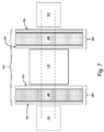
- FIG. 7 illustrates a schematic diagram of volumetric metering assembly 190, in one example.
- guide assembly 182 compressibly fits between a spacer 192 and roller element 178.
- FIG. 7 illustrates a spacer 192 on either side of the assembly 195, however, in one example, there is only one spacer 192 between adjacent guide assemblies 182. In another example, multiple spacers 192 can be disposed between adjacent guide assemblies 182. Each spacer 192 maintains a defined distance between adjacent metering assemblies 190.
- Each spacer 192 comprises, in one example, a bushing-like device axially located on the drive shaft 180.
- spacer 192 is comprises a substantially incompressible spacing mechanism, such as a metal or plastic material.
- spacer 192 can comprise a compressible spacing mechanism, for example a compressible foam, or a compression spring.
- spacer 192 is attached to the frame 150 and not coupled to the drive shaft 180.
- the guide assemblies shown in and described with respect to FIGS. 3-7 are by way of example only. Other suitable guide assemblies could be used.
- the guide element can be spring-loaded.
- the system further may comprise a compressible element that biases the guide element toward the roller element, wherein the compressible element comprises plastic, and particularly polyurethane.
- the compressible element may comprises a spring.
- the guide element might be a first guide element, and the system may comprise a second guide element on a second side of the roller element, wherein the second guide element is biased toward the roller element.
- the volumetric metering system may also comprise a second compressible element.
- a product receiving component comprises a feed cup, and when the first and second compressible elements are in an uncompressed state, a combined axial length of the first guide element, the second guide element, the roller element, the first compressible element, and the second compressible element is greater than a width of the feed cup.
- the guide element comprises one of metal or plastic.
- the drive mechanism may comprise a drive shaft, and further comprise a plurality of roller elements rotationally driven by the drive shaft, each roller element having at least one guide element biased into contact with the roller element.
- a product receiving component comprises a flow path to a product distribution system configured to distribute the product to at least one end point.
- the guide element may comprise a first plate configured to contact the roller element, the guide assembly may further comprise a second plate configured to contact a housing of the volumetric metering roller, and wherein the compressible element is disposed between the first and second plates.
Landscapes
- Life Sciences & Earth Sciences (AREA)
- Soil Sciences (AREA)
- Environmental Sciences (AREA)
- Sowing (AREA)
- Fertilizing (AREA)
Abstract
Description
- The present disclosure relates to a volumetric meter. More specifically, but not by limitation, the present disclosure relates to a volumetric meter having a spring-loaded guide element for metering product in agricultural equipment.
- Volumetric meters are commonly used in agricultural equipment, such as grain drills, air seeders or fertilizer applicators, to meter product (e.g. seed, fertilizer, etc.) during distribution. In one example, a volumetric meter employs one or more metering rollers contained within a housing. The housing has an inlet that receives product from a tank. The tank feeds the product into the housing utilizing a delivery mechanism (e.g. air, gravity, feed mechanisms, etc.). In one particular example, the tank is located above the housing and product is fed into the housing using gravity.
- In one example, the metering rollers can be fluted such that, as the rollers rotate, product from the tank is carried to an outlet in a controlled manner. The rate at which product is conveyed to the outlet is based on the width of the roller, the size of the roller flutes, and the rotation speed of the rollers. From the outlet, the product is then carried by a distribution system for dispensing on or into the soil. In one example, the distribution system includes a number of individual channels or runs, each channel receiving product from a separate roller and delivering the product to a separate set of one or more ground openers.
- The discussion above is merely provided for general background information and is not intended to be used as an aid in determining the scope of the claimed subject matter.
- A volumetric metering system for metering a product in an agricultural machine is presented. In one example, the volumetric metering system comprises a roller element, a drive mechanism configured to rotationally drive the roller element to convey the product along a conveyance path to a product receiving component, and a guide element disposed on a side of the roller element. The guide element is configured to guide the product along the conveyance path, and is biased towards the roller element.
- This Summary is provided to introduce a selection of concepts in a simplified form that are further described below in the Detailed Description. This Summary is not intended to identify key features or essential features of the claimed subject matter, nor is it intended to be used as an aid in determining the scope of the claimed subject matter. The claimed subject matter is not limited to implementations that solve any or all disadvantages noted in the background.
-
-
FIG. 1 illustrates a perspective view of a seeding implement, in one example. -
FIG. 2 illustrates a simplified block diagram for a metering process, in one example. -
FIG. 3 illustrates a perspective view of a volumetric meter assembly, in one example. -
FIG. 4 illustrates a schematic diagram of a portion of the volumetric meter assembly, shown inFIG. 3 . -
FIG. 5 illustrates a perspective view of a volumetric meter assembly, in one example. -
FIG. 6 illustrates a perspective view of a volumetric meter assembly, in one example. -
FIG. 7 illustrates a schematic diagram of a volumetric meter assembly, in one example. -
FIG. 1 illustrates a perspective view of one example of a product distribution vehicle for distributing agricultural product in the form of particulate material (e.g. seed, fertilizer, etc.). In the illustrated example, the vehicle comprises a seeding implement 10 that delivers seed and/or fertilizer to ground engaging openers. Of course, other types of product distribution vehicles can be utilized. - Seeding
implement 10 includes aframe 12 supporting a seed grain box 14. The grain box 14 opens downwardly into seed metering devices (e.g., fluted seed cups) designated generally atreference numeral 16. A plurality of transversely spaced fluted feed wheels orroller elements 18 are driven by asquare drive shaft 20 using a drive mechanism. In one example, the drive mechanism comprises a separate motor, such as an electric motor. In the illustrated example,drive shaft 20 is operably connected toground wheels 22 for metering a desired amount of seed intoseed tubes 24 as the implement is towed forwardly through a field. The metering rate is proportional to the forward speed of the implement. In one example, the seeding rate can be changed by adjusting a ratio of a transmission located betweenground wheels 22 anddrive shaft 20. Of course, this is one example only. Other mechanism for changing the seeding rate can be utilized. - In one example,
seed tubes 24 convey the product to ground openers that place the product in a furrow at a desired depth. Incorporation of seed row finishing equipment, such as closing wheels, can also be utilized. -
FIG. 2 illustrates a simplified block diagram for an example metering process. For example, the process ofFIG. 2 can be performed using seeding implement 10 illustrated inFIG. 1 . - In
block 102, a metering system receives product (e.g.,devices 16 receive seed and/or fertilizer) from a product source mechanism (e.g., grain box 14 or other source). Inblock 104, the metering system meters the product. Examples of this are described in greater detail below. Briefly, however, in one example one or more metering rollers are rotationally driven by a drive shaft or other drive mechanism. The metering rollers, which can be fluted, meter the product in a controlled manner by conveying the product to a product receiving mechanism atblock 106. In one example, the product receiving mechanism comprises an outlet of the metering system that is coupled to an inlet of a distribution system (e.g., seed tubes of a gravity product distribution system, the air stream of distribution system, etc.). - In
block 104, the rate at which product is conveyed to the outlet is based on the width of the roller, the size of the roller flutes, and the rotation speed of the rollers. For a given roller configuration, the metering rate can be adjusted by increasing or decreasing the rotation speed of the roller. In one example, to accommodate different types of product (e.g., different seed types, different fertilizer types, etc.) and/or significant variations in the desired product metering rate, the metering system is configured for use with different types of metering rollers. That is, the metering rollers can be removed and replaced with different roller sizes, shapes, etc. For instance, a narrow roller can be used with crops that require a low application rate and a wider roller can be used with crops that require a high application rate. - Further, in one example, the metering system utilizes spacers positioned between adjacent rollers. The spacers can comprise sidewalls or plates that contact the sides of the rollers. In one example, the spacers form guide elements that are located in contact with, or otherwise in close proximity to, the rollers and aid in locating the rollers along the drive shaft and/or guiding the product along a conveyance path as the rollers rotate. In some scenarios, these types of metering components are susceptible to non-uniform product flowrates. For example, roller geometry variations due to manufacturing tolerances or other reasons can cause unwanted variations in metering rates between the rollers. For instance, product can escape from or become lodged in gaps formed between the roller and spacer as a result of lateral run-out (i.e., side-to-side wobbling of the roller as it rotates). Further, mechanical binding between the rollers and spacers can increase power consumption and cause excessive wear on the associated components.
- In accordance with one example, a metering system utilizes a guide element that is spring-loaded, or otherwise biased, toward the roller. As discussed in further detail below, the guide element can be biased in any of a number of ways. Briefly, however, the guide element can be biased by a compressible element, such as a compression spring or compressible material (e.g., a foam, polymer, etc.). The biased guide element can improve the functionality of a metering system, such as, but not limited to, mitigating the effects of roller geometry variations, reducing row-to-row product flow variation, reducing mechanical binding, reducing component wear, and/or reducing product damage, etc.
-
FIG. 3 illustrates a perspective view of an examplevolumetric meter assembly 120 that is configured to volumetrically meter product and includes biased guide elements. In one example,assembly 120 can be utilized with a pneumatic distribution system, such as on an air seeder or air drill. That is,assembly 120 can be utilized to volumetrically meter product into air streams that pneumatically convey the product to the ground. In another example,assembly 120 can be utilized with a gravity drop distribution system. For the sake of illustration, but not by limitation,assembly 120 will be described in the context of seeding implement 10, shown inFIG. 1 . -
Assembly 120 includes aframe 150 that is located in a housing (not shown inFIG. 3 ) adjacent a lower outlet of a product tank (e.g., grain box 14). The product tank forms, or supplies a product (e.g., seed and/or fertilizer) into, acompartment 148 illustrated inFIG. 3 by dotted lines. A metering system driveshaft 180 is operably coupled to a drive assembly configured to rotatedrive shaft 180. In one example, the drive assembly comprises a separate motor, such as an electric motor. In one example, the drive assembly comprises ground wheels. - Drive
shaft 180 is supported byframe 150. A plurality ofmetering assemblies 190 are located alongshaft 180. Eachassembly 190 comprises a meter roller element that is rotated byshaft 180. In one example, the roller elements and thedrive shaft 180 have corresponding cross section profiles that are non-circular (for example, square, hexagonal, octagonal or oval) to discourage slippage of the roller elements asshaft 180 rotates. Of course, the roller elements can be coupled toshaft 180 in other ways as well. - Adjacent each
metering assembly 190 is afeed cup 168 which is open to the respective roller element, and configured to receive metered product. Eachfeed cup 168 also forms anoutlet tube 169 configured to direct metered product to a product distribution system (not shown inFIG. 3 ). In one example,outlet tubes 169 are coupled to seed tubes (e.g.,seed tubes 24 shown inFIG. 1 ). -
FIG. 4 illustrates a schematic diagram of ametering assembly 190, in one example. InFIG. 4 , components are illustrated in an exploded view.Metering assembly 190 comprises aroller element 178 and at least oneguide assembly 182 located adjacent to, and in contact withroller element 178. While only oneroller element 178 is shown,assembly 190 can include more than one roller element between a pair ofguide assemblies 182. - As shown, two
guide assemblies 182 are adjacently located toroller element 178, such that they engage opposing sides of theroller element 178. In one example,roller elements 178 and guideassemblies 182 can be replaced with other component sizes and combinations (e.g. for different product types and/or meter rates) by removingdrive shaft 180 fromframe 150. - Each
guide assembly 182 comprises, in one example, at least oneguide element 184, and abiasing element 185.Biasing element 185 is configured to exert a biasing force onguide element 184 towardroller element 178. In one example,element 185 comprises a compressible element (referred to as compressible element 185) and/or anelement 186 that engages a surface offrame 150.Compressible element 185 is, in the illustrated example, resilient in that it returns to a normal, relaxed state after being compressed. - In one example,
compressible element 185 comprises a compression-spring. One example is illustrated below inFIG. 6 . In one example,compressible element 185 comprises a compressible, solid material. One example is illustrated below inFIG. 5 . - While
element 184 is illustrated as a separate component fromelement 185, in oneexample element 184 can be formed by a surface ofelement 185. In one example,element 184 and/orelement 186 comprises solid plates, such as metal (e.g., stainless steel), plastic, or another suitable material. In one example,compressible element 185 is formed of a compressible, resilient material. In one example,element 185 comprises an elastic material such as, but not limited to, an elastomeric material. In one example, the compressible material comprises plastic. In one example, the compressible material comprises urethane foam. In one example,compression element 185 exerts a biasing force of at least one pounds per square inch (psi) at a given deflection (e.g. 25% deflection). In one example,compression element 185 exerts a biasing force of at least two psi. In one example,compression element 185 exerts a biasing force of at least three psi at a given deflection. In one example,compression element 185 exerts a biasing force of at least four psi at a given deflection. In one example,compression element 185 exerts a biasing force of at least five psi. -
FIG. 5 illustrates a perspective view of a portion ofvolumetric meter assembly 120, in one example. As shown,meter assembly 190 compressibly fits between adjacent frame protrusions 193 (or other suitable spacing elements), in one example. Alternatively, or in addition,metering assembly 190 compressibly fits withinwalls 194 offeed cup 168. In one example,frame protrusion 193 and feedcup wall 194 are formed of a single unitary body. In one example, the feed cup diameter is substantially similar to the distance betweenadjacent frame protrusions 193, such that both feedcup walls 194 andframe protrusions 193 provide a biasing force againstelements 186. In a relaxed, uncompressed state, eachmetering assembly 190 has a width greater than the width betweenframe protrusions 193 and/or feedcup walls 194. - During operation of
assembly 120,roller elements 178 and/or guideassemblies 182 are exposed to product in compartment 148 (shown inFIG. 3 ). As theroller elements 178 rotate, they convey product to feedcups 168.Guide assemblies 182 assist in guiding the product along the conveyance path. As such,guide assemblies 182 can act as a product barrier that prevents product from escaping the intended path of conveyance on the metering surface ofroller element 178 and entering into other areas ofmeter assembly 120. -
FIG. 6 illustrates a perspective view of a volumetric meter assembly, in one example. In the example ofFIG. 6 , acompressible guide assembly 187 comprises a compression spring 188 (shown in phantom inFIG. 6 ).Spring 188 is configured to provide a biasing force onguide element 189 against aroller element 191. In the example illustrated inFIG. 6 ,assembly 187 comprises aproduct barrier 196 configured to prevent product from entering a space on an opposing side ofelement 189, that isopposite roller element 191. In one example, theproduct barrier 196 comprises a telescoping shield. In one example, theproduct barrier 196 comprises bellows. In one example, theproduct barrier 196 comprises a foam or other material having a cavity (such as a hollowed out portion) that accommodatesspring 188. Of course, other suitable product barriers can also be utilized. -
FIG. 7 illustrates a schematic diagram ofvolumetric metering assembly 190, in one example. InFIG. 7 , the components are illustrated in an exploded view. In the example ofFIG. 7 , guideassembly 182 compressibly fits between aspacer 192 androller element 178.FIG. 7 illustrates aspacer 192 on either side of the assembly 195, however, in one example, there is only onespacer 192 betweenadjacent guide assemblies 182. In another example,multiple spacers 192 can be disposed betweenadjacent guide assemblies 182. Eachspacer 192 maintains a defined distance betweenadjacent metering assemblies 190. Eachspacer 192 comprises, in one example, a bushing-like device axially located on thedrive shaft 180. In one example,spacer 192 is comprises a substantially incompressible spacing mechanism, such as a metal or plastic material. In one example,spacer 192 can comprise a compressible spacing mechanism, for example a compressible foam, or a compression spring. In one example,spacer 192 is attached to theframe 150 and not coupled to thedrive shaft 180. - The guide assemblies shown in and described with respect to
FIGS. 3-7 are by way of example only. Other suitable guide assemblies could be used. - It should also be noted that the different embodiments described herein can be combined in different ways. That is, parts of one or more embodiments can be combined with parts of one or more other embodiments. All of this is contemplated herein.
- In a summary, a volumetric metering system for metering a product in an agricultural machine comprises a roller element, a drive mechanism configured to rotationally drive the roller element to convey the product along a conveyance path to a product receiving component, and a guide element disposed on a side of the roller element and configured to guide the product along the conveyance path, wherein the guide element is biased towards the roller element. The guide element can be spring-loaded. The system further may comprise a compressible element that biases the guide element toward the roller element, wherein the compressible element comprises plastic, and particularly polyurethane. The compressible element may comprises a spring. The guide element might be a first guide element, and the system may comprise a second guide element on a second side of the roller element, wherein the second guide element is biased toward the roller element. The volumetric metering system may also comprise a second compressible element.
- A product receiving component comprises a feed cup, and when the first and second compressible elements are in an uncompressed state, a combined axial length of the first guide element, the second guide element, the roller element, the first compressible element, and the second compressible element is greater than a width of the feed cup. The guide element comprises one of metal or plastic. The drive mechanism may comprise a drive shaft, and further comprise a plurality of roller elements rotationally driven by the drive shaft, each roller element having at least one guide element biased into contact with the roller element. A product receiving component comprises a flow path to a product distribution system configured to distribute the product to at least one end point.
- The guide element may comprise a first plate configured to contact the roller element, the guide assembly may further comprise a second plate configured to contact a housing of the volumetric metering roller, and wherein the compressible element is disposed between the first and second plates.
Claims (13)
- A volumetric metering system (190) for metering a product in an agricultural machine, the system comprising:a roller element (178);a drive mechanism configured to rotationally drive the roller element (178) to convey the product along a conveyance path to a product receiving component; anda guide element (184) disposed on a side of the roller element (178) and configured to guide the product along the conveyance path, wherein the guide element (184) is biased towards the roller element (178).
- The volumetric metering system of claim 1, wherein the guide element (184) is springloaded.
- The volumetric metering system (190) of claim 2, and further comprising a compressible element (185) that biases the guide element (184) toward the roller element (178).
- The volumetric metering system (190) of claim 3, wherein the compressible element (185) comprises plastic.
- The volumetric metering system (190) of claim 4, wherein the compressible element (185) comprises polyurethane.
- The volumetric metering system (190) of claim 3, wherein the compressible element (185) comprises a spring (188).
- The volumetric metering system (190) of claim 3, wherein the guide element (184) is a first guide element (184), and further comprising a second guide element (184) on a second side of the roller element (178).
- The volumetric metering system (190) of claim 7, wherein the second guide element (184) is biased toward the roller element (178).
- The volumetric metering system (190) of claim 8, wherein the second guide element (184) comprises a second compressible element (185).
- The volumetric metering system (190) of claim 9, wherein the product receiving component comprises a feed cup (168), and when the first and second compressible elements (185) are in an uncompressed state, a combined axial length of the first guide element (184), the second guide element (184), the roller element (178), the first compressible element (185), and the second compressible element (185) is greater than a width of the feed cup (168).
- The volumetric metering system (190) of claim 1, wherein the guide element (184) comprises one of metal or plastic.
- The volumetric metering system (190) of claim 1, wherein the drive mechanism comprises a drive shaft (180), and further comprising a plurality of roller elements (178) rotationally driven by the drive shaft (180), each roller element (178) having at least one guide element (184) biased into contact with the roller element (178).
- The volumetric metering system (190) of claim 1, wherein the product receiving component comprises a flow path to a product distribution system configured to distribute the product to at least one end point.
Applications Claiming Priority (1)
| Application Number | Priority Date | Filing Date | Title |
|---|---|---|---|
| US14/862,560 US9861030B2 (en) | 2015-09-23 | 2015-09-23 | Biased guide to reduce variation in a volumetric meter |
Publications (2)
| Publication Number | Publication Date |
|---|---|
| EP3146828A1 true EP3146828A1 (en) | 2017-03-29 |
| EP3146828B1 EP3146828B1 (en) | 2018-12-26 |
Family
ID=57046976
Family Applications (1)
| Application Number | Title | Priority Date | Filing Date |
|---|---|---|---|
| EP16189499.3A Active EP3146828B1 (en) | 2015-09-23 | 2016-09-19 | Volumetric meter assembly |
Country Status (4)
| Country | Link |
|---|---|
| US (1) | US9861030B2 (en) |
| EP (1) | EP3146828B1 (en) |
| AU (3) | AU2016219632A1 (en) |
| CA (1) | CA2939054A1 (en) |
Cited By (4)
| Publication number | Priority date | Publication date | Assignee | Title |
|---|---|---|---|---|
| WO2020169277A1 (en) * | 2019-02-21 | 2020-08-27 | Amazonen-Werke H. Dreyer Gmbh & Co. Kg | Metering device for granular material and distribution machine having metering device |
| EP3815500A1 (en) * | 2019-10-31 | 2021-05-05 | Deere & Company | Volumetric metering system and method of determining roller information in such system |
| US11579590B2 (en) | 2019-10-31 | 2023-02-14 | Deere & Company | Wireless mobile work machine component detection and control system |
| US12284936B2 (en) | 2021-03-08 | 2025-04-29 | Deere & Company | Row unit plugging detection and control system |
Families Citing this family (14)
| Publication number | Priority date | Publication date | Assignee | Title |
|---|---|---|---|---|
| CN109089491B (en) * | 2018-08-08 | 2021-06-15 | 林龙 | Peanut seeder |
| US11564346B2 (en) | 2019-12-24 | 2023-01-31 | Cnh Industrial America Llc | Particle delivery system of an agricultural row unit |
| US11582899B2 (en) | 2019-12-24 | 2023-02-21 | Cnh Industrial America Llc | Particle delivery system of an agricultural row unit |
| US11596095B2 (en) | 2019-12-24 | 2023-03-07 | Cnh Industrial America Llc | Particle delivery system of an agricultural row unit |
| US11553639B2 (en) | 2019-12-24 | 2023-01-17 | Cnh Industrial America Llc | Particle delivery system of an agricultural row unit |
| US11564344B2 (en) | 2019-12-24 | 2023-01-31 | Cnh Industrial America Llc | Particle delivery system of an agricultural row unit |
| US11490558B2 (en) | 2019-12-24 | 2022-11-08 | Cnh Industrial America Llc | Particle delivery system of an agricultural row unit |
| US11483963B2 (en) | 2019-12-24 | 2022-11-01 | Cnh Industrial America Llc | Particle delivery system of an agricultural row unit |
| US11553638B2 (en) | 2019-12-24 | 2023-01-17 | Cnh Industrial America Llc | Particle delivery system of an agricultural row unit |
| US11523555B2 (en) | 2019-12-24 | 2022-12-13 | Cnh Industrial America Llc | Particle delivery system of an agricultural row unit |
| US11589500B2 (en) | 2019-12-24 | 2023-02-28 | Cnh Industrial America Llc | Particle delivery system of an agricultural row unit |
| US11516958B2 (en) | 2019-12-24 | 2022-12-06 | Cnh Industrial America Llc | Particle delivery system of an agricultural row unit |
| US11523556B2 (en) | 2019-12-24 | 2022-12-13 | Cnh Industrial America Llc | Particle delivery system of an agricultural row unit |
| CN112119708B (en) * | 2020-10-10 | 2021-06-01 | 山西省农业科学院旱地农业研究中心 | Air-suction type bean seeder |
Citations (4)
| Publication number | Priority date | Publication date | Assignee | Title |
|---|---|---|---|---|
| US2757825A (en) * | 1953-07-06 | 1956-08-07 | Allis Chalmers Mfg Co | Seed rate adjustment |
| US4131221A (en) * | 1976-08-13 | 1978-12-26 | Lambert Corporation | Planting and fertilizing apparatus |
| DE8811286U1 (en) * | 1988-09-07 | 1988-11-10 | Rabewerk Heinrich Clausing, 4515 Bad Essen | Dosing device for a distribution machine |
| EP2260689A1 (en) * | 2009-06-09 | 2010-12-15 | Deere & Company | Metering system |
Family Cites Families (6)
| Publication number | Priority date | Publication date | Assignee | Title |
|---|---|---|---|---|
| US1712797A (en) * | 1926-06-14 | 1929-05-14 | Int Harvester Co | Grain-drill feed |
| CA2272504C (en) * | 1998-05-22 | 2011-02-15 | Flexi-Coil Ltd. | Segmented meter roller assembly |
| US6109192A (en) | 1999-09-20 | 2000-08-29 | Deere & Company | Power rate adjustment mechanism for a seeding implement |
| US6308645B1 (en) * | 1999-12-30 | 2001-10-30 | Great Plains Manufacturing, Incorporated | Seeding machine with bulk seed supply container and independent, opener-mounted metering devices |
| US6571868B2 (en) * | 2000-09-08 | 2003-06-03 | Bruce M. Victor | Well head lubricator assembly with polyurethane impact-absorbing spring |
| US8196534B2 (en) | 2009-12-03 | 2012-06-12 | Deere & Company | Volumetric metering system with clutch based sectional shut-off |
-
2015
- 2015-09-23 US US14/862,560 patent/US9861030B2/en active Active
-
2016
- 2016-08-16 CA CA2939054A patent/CA2939054A1/en not_active Abandoned
- 2016-08-25 AU AU2016219632A patent/AU2016219632A1/en not_active Abandoned
- 2016-09-19 EP EP16189499.3A patent/EP3146828B1/en active Active
-
2021
- 2021-06-10 AU AU2021203841A patent/AU2021203841A1/en not_active Abandoned
-
2023
- 2023-09-28 AU AU2023237132A patent/AU2023237132B2/en active Active
Patent Citations (4)
| Publication number | Priority date | Publication date | Assignee | Title |
|---|---|---|---|---|
| US2757825A (en) * | 1953-07-06 | 1956-08-07 | Allis Chalmers Mfg Co | Seed rate adjustment |
| US4131221A (en) * | 1976-08-13 | 1978-12-26 | Lambert Corporation | Planting and fertilizing apparatus |
| DE8811286U1 (en) * | 1988-09-07 | 1988-11-10 | Rabewerk Heinrich Clausing, 4515 Bad Essen | Dosing device for a distribution machine |
| EP2260689A1 (en) * | 2009-06-09 | 2010-12-15 | Deere & Company | Metering system |
Cited By (8)
| Publication number | Priority date | Publication date | Assignee | Title |
|---|---|---|---|---|
| WO2020169277A1 (en) * | 2019-02-21 | 2020-08-27 | Amazonen-Werke H. Dreyer Gmbh & Co. Kg | Metering device for granular material and distribution machine having metering device |
| US12052946B2 (en) | 2019-02-21 | 2024-08-06 | Amazonen-Werke H. Dreyer SE & Co. KG | Metering device for granular material and distribution machine having metering device |
| EP3815500A1 (en) * | 2019-10-31 | 2021-05-05 | Deere & Company | Volumetric metering system and method of determining roller information in such system |
| EP3815501A1 (en) * | 2019-10-31 | 2021-05-05 | Deere & Company | Volumetric metering system |
| US11579590B2 (en) | 2019-10-31 | 2023-02-14 | Deere & Company | Wireless mobile work machine component detection and control system |
| US12063882B2 (en) | 2019-10-31 | 2024-08-20 | Deere & Company | Volumetric metering system with improved roller detection |
| US12189368B2 (en) | 2019-10-31 | 2025-01-07 | Deere & Company | Wireless mobile work machine component detection and control system |
| US12284936B2 (en) | 2021-03-08 | 2025-04-29 | Deere & Company | Row unit plugging detection and control system |
Also Published As
| Publication number | Publication date |
|---|---|
| AU2016219632A1 (en) | 2017-04-06 |
| AU2023237132B2 (en) | 2025-09-04 |
| EP3146828B1 (en) | 2018-12-26 |
| AU2021203841A1 (en) | 2021-07-08 |
| US9861030B2 (en) | 2018-01-09 |
| AU2023237132A1 (en) | 2023-10-19 |
| CA2939054A1 (en) | 2017-03-23 |
| US20170079199A1 (en) | 2017-03-23 |
Similar Documents
| Publication | Publication Date | Title |
|---|---|---|
| AU2023237132B2 (en) | Spring-loaded guide to reduce variation in a volumetric meter | |
| CA2616239C (en) | Variable displacement meter roller | |
| CA2451066C (en) | Seed slide for use in an agricultural seeding machine | |
| RU2586899C2 (en) | Sowing section for seeder, planter and seeding method | |
| US5996515A (en) | Axial retainer shaft for meter roller | |
| EP3219186B1 (en) | Row unit of an agricultural machine, and method for operating an agricultural machine | |
| US9924627B1 (en) | Modular metering apparatus for an air seeder | |
| CA2451064C (en) | Seed placement system for use in a seeding machine | |
| CA2451722C (en) | Seed metering system for use in a seeding machine | |
| US8733259B2 (en) | Seed metering apparatus for a seeder | |
| CN100545590C (en) | Volumetric metering devices for the quantitative delivery of granular and powdery materials, in particular for machines for dispensing said materials | |
| US20150216109A1 (en) | Metering assembly with individually driven metering sections | |
| US10197427B2 (en) | Meter roller for an agricultural metering system | |
| WO2021198379A1 (en) | Spreading machine | |
| WO2011037525A1 (en) | Seed metering device on an agricultural machine | |
| AU2007201262A1 (en) | Dispenser | |
| DE60304979T2 (en) | Dosing device for a seed drill, which can distribute several products at the same time | |
| DE202022103848U1 (en) | Dosing unit for powdered or particulate material to be distributed and distribution machine with such a dosing unit | |
| US9769976B2 (en) | Flow control assembly for an agricultural metering system | |
| CN107426962B (en) | Feeding device for agricultural machinery | |
| DE202020005437U1 (en) | Distribution machine | |
| DE3831619A1 (en) | Method for sowing seed grains with a seed drill | |
| AU1004502A (en) | Dispenser |
Legal Events
| Date | Code | Title | Description |
|---|---|---|---|
| PUAI | Public reference made under article 153(3) epc to a published international application that has entered the european phase |
Free format text: ORIGINAL CODE: 0009012 |
|
| STAA | Information on the status of an ep patent application or granted ep patent |
Free format text: STATUS: THE APPLICATION HAS BEEN PUBLISHED |
|
| AK | Designated contracting states |
Kind code of ref document: A1 Designated state(s): AL AT BE BG CH CY CZ DE DK EE ES FI FR GB GR HR HU IE IS IT LI LT LU LV MC MK MT NL NO PL PT RO RS SE SI SK SM TR |
|
| AX | Request for extension of the european patent |
Extension state: BA ME |
|
| STAA | Information on the status of an ep patent application or granted ep patent |
Free format text: STATUS: REQUEST FOR EXAMINATION WAS MADE |
|
| 17P | Request for examination filed |
Effective date: 20170929 |
|
| RBV | Designated contracting states (corrected) |
Designated state(s): AL AT BE BG CH CY CZ DE DK EE ES FI FR GB GR HR HU IE IS IT LI LT LU LV MC MK MT NL NO PL PT RO RS SE SI SK SM TR |
|
| REG | Reference to a national code |
Ref country code: DE Ref legal event code: R079 Ref document number: 602016008638 Country of ref document: DE Free format text: PREVIOUS MAIN CLASS: A01C0007120000 Ipc: A01C0007080000 |
|
| GRAP | Despatch of communication of intention to grant a patent |
Free format text: ORIGINAL CODE: EPIDOSNIGR1 |
|
| STAA | Information on the status of an ep patent application or granted ep patent |
Free format text: STATUS: GRANT OF PATENT IS INTENDED |
|
| RIC1 | Information provided on ipc code assigned before grant |
Ipc: A01C 7/12 20060101ALI20180625BHEP Ipc: A01C 7/08 20060101AFI20180625BHEP |
|
| INTG | Intention to grant announced |
Effective date: 20180711 |
|
| GRAS | Grant fee paid |
Free format text: ORIGINAL CODE: EPIDOSNIGR3 |
|
| GRAA | (expected) grant |
Free format text: ORIGINAL CODE: 0009210 |
|
| STAA | Information on the status of an ep patent application or granted ep patent |
Free format text: STATUS: THE PATENT HAS BEEN GRANTED |
|
| AK | Designated contracting states |
Kind code of ref document: B1 Designated state(s): AL AT BE BG CH CY CZ DE DK EE ES FI FR GB GR HR HU IE IS IT LI LT LU LV MC MK MT NL NO PL PT RO RS SE SI SK SM TR |
|
| REG | Reference to a national code |
Ref country code: GB Ref legal event code: FG4D |
|
| REG | Reference to a national code |
Ref country code: CH Ref legal event code: EP |
|
| REG | Reference to a national code |
Ref country code: AT Ref legal event code: REF Ref document number: 1080110 Country of ref document: AT Kind code of ref document: T Effective date: 20190115 |
|
| REG | Reference to a national code |
Ref country code: DE Ref legal event code: R096 Ref document number: 602016008638 Country of ref document: DE |
|
| REG | Reference to a national code |
Ref country code: IE Ref legal event code: FG4D |
|
| PG25 | Lapsed in a contracting state [announced via postgrant information from national office to epo] |
Ref country code: FI Free format text: LAPSE BECAUSE OF FAILURE TO SUBMIT A TRANSLATION OF THE DESCRIPTION OR TO PAY THE FEE WITHIN THE PRESCRIBED TIME-LIMIT Effective date: 20181226 Ref country code: LV Free format text: LAPSE BECAUSE OF FAILURE TO SUBMIT A TRANSLATION OF THE DESCRIPTION OR TO PAY THE FEE WITHIN THE PRESCRIBED TIME-LIMIT Effective date: 20181226 Ref country code: NO Free format text: LAPSE BECAUSE OF FAILURE TO SUBMIT A TRANSLATION OF THE DESCRIPTION OR TO PAY THE FEE WITHIN THE PRESCRIBED TIME-LIMIT Effective date: 20190326 Ref country code: HR Free format text: LAPSE BECAUSE OF FAILURE TO SUBMIT A TRANSLATION OF THE DESCRIPTION OR TO PAY THE FEE WITHIN THE PRESCRIBED TIME-LIMIT Effective date: 20181226 Ref country code: BG Free format text: LAPSE BECAUSE OF FAILURE TO SUBMIT A TRANSLATION OF THE DESCRIPTION OR TO PAY THE FEE WITHIN THE PRESCRIBED TIME-LIMIT Effective date: 20190326 Ref country code: LT Free format text: LAPSE BECAUSE OF FAILURE TO SUBMIT A TRANSLATION OF THE DESCRIPTION OR TO PAY THE FEE WITHIN THE PRESCRIBED TIME-LIMIT Effective date: 20181226 |
|
| REG | Reference to a national code |
Ref country code: NL Ref legal event code: MP Effective date: 20181226 |
|
| REG | Reference to a national code |
Ref country code: LT Ref legal event code: MG4D |
|
| PG25 | Lapsed in a contracting state [announced via postgrant information from national office to epo] |
Ref country code: AL Free format text: LAPSE BECAUSE OF FAILURE TO SUBMIT A TRANSLATION OF THE DESCRIPTION OR TO PAY THE FEE WITHIN THE PRESCRIBED TIME-LIMIT Effective date: 20181226 Ref country code: GR Free format text: LAPSE BECAUSE OF FAILURE TO SUBMIT A TRANSLATION OF THE DESCRIPTION OR TO PAY THE FEE WITHIN THE PRESCRIBED TIME-LIMIT Effective date: 20190327 Ref country code: SE Free format text: LAPSE BECAUSE OF FAILURE TO SUBMIT A TRANSLATION OF THE DESCRIPTION OR TO PAY THE FEE WITHIN THE PRESCRIBED TIME-LIMIT Effective date: 20181226 Ref country code: RS Free format text: LAPSE BECAUSE OF FAILURE TO SUBMIT A TRANSLATION OF THE DESCRIPTION OR TO PAY THE FEE WITHIN THE PRESCRIBED TIME-LIMIT Effective date: 20181226 |
|
| REG | Reference to a national code |
Ref country code: AT Ref legal event code: MK05 Ref document number: 1080110 Country of ref document: AT Kind code of ref document: T Effective date: 20181226 |
|
| PG25 | Lapsed in a contracting state [announced via postgrant information from national office to epo] |
Ref country code: NL Free format text: LAPSE BECAUSE OF FAILURE TO SUBMIT A TRANSLATION OF THE DESCRIPTION OR TO PAY THE FEE WITHIN THE PRESCRIBED TIME-LIMIT Effective date: 20181226 |
|
| PG25 | Lapsed in a contracting state [announced via postgrant information from national office to epo] |
Ref country code: PT Free format text: LAPSE BECAUSE OF FAILURE TO SUBMIT A TRANSLATION OF THE DESCRIPTION OR TO PAY THE FEE WITHIN THE PRESCRIBED TIME-LIMIT Effective date: 20190426 Ref country code: IT Free format text: LAPSE BECAUSE OF FAILURE TO SUBMIT A TRANSLATION OF THE DESCRIPTION OR TO PAY THE FEE WITHIN THE PRESCRIBED TIME-LIMIT Effective date: 20181226 Ref country code: ES Free format text: LAPSE BECAUSE OF FAILURE TO SUBMIT A TRANSLATION OF THE DESCRIPTION OR TO PAY THE FEE WITHIN THE PRESCRIBED TIME-LIMIT Effective date: 20181226 Ref country code: CZ Free format text: LAPSE BECAUSE OF FAILURE TO SUBMIT A TRANSLATION OF THE DESCRIPTION OR TO PAY THE FEE WITHIN THE PRESCRIBED TIME-LIMIT Effective date: 20181226 Ref country code: PL Free format text: LAPSE BECAUSE OF FAILURE TO SUBMIT A TRANSLATION OF THE DESCRIPTION OR TO PAY THE FEE WITHIN THE PRESCRIBED TIME-LIMIT Effective date: 20181226 |
|
| PG25 | Lapsed in a contracting state [announced via postgrant information from national office to epo] |
Ref country code: SM Free format text: LAPSE BECAUSE OF FAILURE TO SUBMIT A TRANSLATION OF THE DESCRIPTION OR TO PAY THE FEE WITHIN THE PRESCRIBED TIME-LIMIT Effective date: 20181226 Ref country code: EE Free format text: LAPSE BECAUSE OF FAILURE TO SUBMIT A TRANSLATION OF THE DESCRIPTION OR TO PAY THE FEE WITHIN THE PRESCRIBED TIME-LIMIT Effective date: 20181226 Ref country code: SK Free format text: LAPSE BECAUSE OF FAILURE TO SUBMIT A TRANSLATION OF THE DESCRIPTION OR TO PAY THE FEE WITHIN THE PRESCRIBED TIME-LIMIT Effective date: 20181226 Ref country code: IS Free format text: LAPSE BECAUSE OF FAILURE TO SUBMIT A TRANSLATION OF THE DESCRIPTION OR TO PAY THE FEE WITHIN THE PRESCRIBED TIME-LIMIT Effective date: 20190426 Ref country code: RO Free format text: LAPSE BECAUSE OF FAILURE TO SUBMIT A TRANSLATION OF THE DESCRIPTION OR TO PAY THE FEE WITHIN THE PRESCRIBED TIME-LIMIT Effective date: 20181226 |
|
| REG | Reference to a national code |
Ref country code: DE Ref legal event code: R097 Ref document number: 602016008638 Country of ref document: DE |
|
| PG25 | Lapsed in a contracting state [announced via postgrant information from national office to epo] |
Ref country code: DK Free format text: LAPSE BECAUSE OF FAILURE TO SUBMIT A TRANSLATION OF THE DESCRIPTION OR TO PAY THE FEE WITHIN THE PRESCRIBED TIME-LIMIT Effective date: 20181226 Ref country code: AT Free format text: LAPSE BECAUSE OF FAILURE TO SUBMIT A TRANSLATION OF THE DESCRIPTION OR TO PAY THE FEE WITHIN THE PRESCRIBED TIME-LIMIT Effective date: 20181226 |
|
| PLBE | No opposition filed within time limit |
Free format text: ORIGINAL CODE: 0009261 |
|
| STAA | Information on the status of an ep patent application or granted ep patent |
Free format text: STATUS: NO OPPOSITION FILED WITHIN TIME LIMIT |
|
| 26N | No opposition filed |
Effective date: 20190927 |
|
| PG25 | Lapsed in a contracting state [announced via postgrant information from national office to epo] |
Ref country code: SI Free format text: LAPSE BECAUSE OF FAILURE TO SUBMIT A TRANSLATION OF THE DESCRIPTION OR TO PAY THE FEE WITHIN THE PRESCRIBED TIME-LIMIT Effective date: 20181226 |
|
| PG25 | Lapsed in a contracting state [announced via postgrant information from national office to epo] |
Ref country code: TR Free format text: LAPSE BECAUSE OF FAILURE TO SUBMIT A TRANSLATION OF THE DESCRIPTION OR TO PAY THE FEE WITHIN THE PRESCRIBED TIME-LIMIT Effective date: 20181226 |
|
| PG25 | Lapsed in a contracting state [announced via postgrant information from national office to epo] |
Ref country code: MC Free format text: LAPSE BECAUSE OF FAILURE TO SUBMIT A TRANSLATION OF THE DESCRIPTION OR TO PAY THE FEE WITHIN THE PRESCRIBED TIME-LIMIT Effective date: 20181226 |
|
| REG | Reference to a national code |
Ref country code: CH Ref legal event code: PL |
|
| PG25 | Lapsed in a contracting state [announced via postgrant information from national office to epo] |
Ref country code: CH Free format text: LAPSE BECAUSE OF NON-PAYMENT OF DUE FEES Effective date: 20190930 Ref country code: LI Free format text: LAPSE BECAUSE OF NON-PAYMENT OF DUE FEES Effective date: 20190930 Ref country code: LU Free format text: LAPSE BECAUSE OF NON-PAYMENT OF DUE FEES Effective date: 20190919 Ref country code: IE Free format text: LAPSE BECAUSE OF NON-PAYMENT OF DUE FEES Effective date: 20190919 |
|
| REG | Reference to a national code |
Ref country code: BE Ref legal event code: MM Effective date: 20190930 |
|
| PG25 | Lapsed in a contracting state [announced via postgrant information from national office to epo] |
Ref country code: BE Free format text: LAPSE BECAUSE OF NON-PAYMENT OF DUE FEES Effective date: 20190930 |
|
| GBPC | Gb: european patent ceased through non-payment of renewal fee |
Effective date: 20200919 |
|
| PG25 | Lapsed in a contracting state [announced via postgrant information from national office to epo] |
Ref country code: CY Free format text: LAPSE BECAUSE OF FAILURE TO SUBMIT A TRANSLATION OF THE DESCRIPTION OR TO PAY THE FEE WITHIN THE PRESCRIBED TIME-LIMIT Effective date: 20181226 |
|
| PG25 | Lapsed in a contracting state [announced via postgrant information from national office to epo] |
Ref country code: MT Free format text: LAPSE BECAUSE OF FAILURE TO SUBMIT A TRANSLATION OF THE DESCRIPTION OR TO PAY THE FEE WITHIN THE PRESCRIBED TIME-LIMIT Effective date: 20181226 Ref country code: HU Free format text: LAPSE BECAUSE OF FAILURE TO SUBMIT A TRANSLATION OF THE DESCRIPTION OR TO PAY THE FEE WITHIN THE PRESCRIBED TIME-LIMIT; INVALID AB INITIO Effective date: 20160919 |
|
| PG25 | Lapsed in a contracting state [announced via postgrant information from national office to epo] |
Ref country code: GB Free format text: LAPSE BECAUSE OF NON-PAYMENT OF DUE FEES Effective date: 20200919 |
|
| PG25 | Lapsed in a contracting state [announced via postgrant information from national office to epo] |
Ref country code: MK Free format text: LAPSE BECAUSE OF FAILURE TO SUBMIT A TRANSLATION OF THE DESCRIPTION OR TO PAY THE FEE WITHIN THE PRESCRIBED TIME-LIMIT Effective date: 20181226 |
|
| PGFP | Annual fee paid to national office [announced via postgrant information from national office to epo] |
Ref country code: DE Payment date: 20250820 Year of fee payment: 10 |
|
| PGFP | Annual fee paid to national office [announced via postgrant information from national office to epo] |
Ref country code: FR Payment date: 20250925 Year of fee payment: 10 |